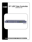
1
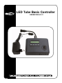
LED Tube Basic Controller
ORDERCODE 41011
Congratulations!
You have bought a great, innovative product from Showtec.
The Showtec LED Tube Basic Controller brings excitement to any venue. Whether you want simple plug-&play action or a sophisticated DMX show, this product provides the effect you need.
You can rely on Showtec, for more excellent lighting products.
We design and manufacture professional light equipment for the entertainment industry.
New products are being launched regularly. We work hard to keep you, our customer, satisfied.
For more information: [email protected]
You can get some of the best quality, best priced products on the market from Showtec.
So next time, turn to Showtec for more great lighting equipment.
Always get the best -- with Showtec !
Thank you!
Showtec
Showtec LED Tube Basic Controller™ Product Guide
Warning..…...................................................................................………………………………………….
Safety-instructions………………………………………………………………………………………….….
Operating Determinations…………………………………………………………………………………….
2
2
3
Description..…..............................................................................……….…………………………………
Features…….……………………………………………………………………………………….……...….
Overview………………………………………………………………………………………………………..
Backside………………………………………………………………………………………………………..
4
4
4
4
41010 LED Tube Basic.…...............................................…...…………………………………….………....
5
Installation...............................................................................…...…………………………………….…...
Installing the tube………………………………………………………………………………….……...……
5
5
Set Up and Operation.....................................................................……..…………………………….……
Stand-alone………..………………………………………………………………………..….………….……
Set up options Controller………………………………………………………………………………………
DMX-controlled………………………………………………………………………..….………….…………
6
7
7
8
Set Up Example...................................................................................…………...….…….………….…...
9
Maintenance...................................................................................………..………….…….……………...
10
Troubleshooting............................................................................………………….………………….…..
10
Product Specifications.................................................................……………….…….…………………..
11
1
WARNING
CAUTION!
Keep this device away from rain and moisture!
Unplug mains lead before opening the housing!
FOR YOUR OWN SAFETY, PLEASE READ THIS USER MANUAL CAREFULLY
BEFORE YOUR INITIAL START-UP!
SAFETY INSTRUCTIONS
Every person involved with the installation, operation and maintenance of this device has to:
be qualified
follow the instructions of this manual
CAUTION! Be careful with your operations.
With a dangerous voltage you can suffer
a dangerous electric shock when touching the wires!
Before your initial start-up, please make sure that there is no damage caused by transportation. Should
there be any, consult your dealer and do not use the device.
To maintain perfect condition and to ensure a safe operation, it is absolutely necessary for the user to follow
the safety instructions and warning notes written in this manual.
Please consider that damages caused by manual modifications to the device are not subject to warranty.
This device contains no user-serviceable parts. Refer servicing to qualified technicians only.
IMPORTANT:
The manufacturer will not accept liability for any resulting damages caused by the non-observance of
this manual or any unauthorized modification to the device.
•
•
•
•
•
•
•
•
•
•
•
•
•
•
Never let the power-cord come into contact with other cables! Handle the power-cord and all
connections with the mains with particular caution!
Never remove warning or informative labels from the unit.
Never look directly into the light source.
Never leave any cables lying around.
Do not open the device and do not modify the device.
Do not connect this device to a dimmerpack.
Do not switch the device on and off in short intervals, as this would reduce the system’s life.
Only use device indoor, avoid contact with water or other liquids.
Avoid flames and do not put close to flammable liquids or gases.
Always disconnect power from the mains, when device is not used or before cleaning! Only handle
the power-cord by the plug. Never pull out the plug by tugging the power-cord.
Make sure that the device is not exposed to extreme heat, moisture or dust.
Make sure that the available voltage is not higher than stated on the rear panel.
Make sure that the power-cord is never crimped or damaged. Check the device and the power-cord
from time to time.
If device is dropped or struck, disconnect mains power supply immediately. Have a qualified
engineer inspect for safety before operating.
2
•
•
•
•
•
If the device has been exposed to drastic temperature fluctuation (e.g. after transportation), do not
switch it on immediately. The arising condensation water might damage your device. Leave the
device switched off until it has reached room temperature.
If your Showtec device fails to work properly, discontinue use immediately. Pack the unit securely
(preferably in the original packing material), and return it to your Showtec dealer for service.
For replacement use fuses of same type and rating only.
Repairs, servicing and electric connection must be carried out by a qualified technician.
WARRANTY: Till one year after date of purchase.
CAUTION ! EYEDAMAGES !.
Avoid looking directly into the light source.
(meant especially for epileptics) !
OPERATING DETERMINATIONS
If this device is operated in any other way, than the one described in this manual, the product may suffer
damages and the warranty becomes void.
Any other operation may lead to dangers like short-circuit, burns, electric shock, lamp explosion, crash etc.
You endanger your own safety and the safety of others!
Improper installation can cause serious damage to people and property !
Rigging
Please follow the European and national guidelines concerning rigging, trussing and all other safety issues.
Do not attempt the installation yourself !
Always let the installation be carried out by an authorized dealer !
Procedure:
•
•
•
•
•
If a LED tube is lowered from the ceiling or high joists, professional trussing systems have to be
used.
Mount the LED tube to the trussing system.
The LED tube must never be fixed swinging freely in the room.
The installation must always be secured with a safety attachment, e.g. an appropriate safety net or
safety-cable.
When rigging, derigging or servicing the LED tube, always make sure, that the area below the
installation place is blocked and staying in the area is forbidden.
Improper installation can cause serious damage to people and property !
3
Description of the device
Features
The LED Tube Basic Controller is designed for the more demanding user:
• 5 DMX Channels
• Controllable DMX or Stand-alone controller.
• 4000 Tubes can be controlled
• 38 programs
• DMX IN and DMX OUT.
Overview
Fig. 1
1) LCD Display
2) Mode: Change the pre-programmed modes.
3) Set Up: Change the settings of the pre-programmed modes (Speed, Flash, Colors)
4) Adjust Up: Increase the DMX address or program options.
5) Adjust Down: Decrease the DMX address or program options.
6) ON / OFF
Backside
Fig. 2
7) 3 pin DMX IN connector: XLR male socket used to receive DMX signals.
8) 3 pin DMX OUT connector: XLR female socket used to send DMX signals.
9) Output to LED Tube
10) Power 12V DC
4
41010 LED TUBE BASIC
Fig. 3
1) Signal Input: Low voltage Signal Input must be connected to the Signal Output (6) of the previous tube or
with the Signal Output cable from the LED Tube Basic controller.
2) Ground: Be sure to ground the LED tube properly.
3) Mains Input Cable: This cable must be connected to the Mains Output (5) of the previous tube or
to any mains wall socket
4) Aluminum Tube Holder: To install the tube on a surface.
5) Mains Output Cable: This cable must be connected to the Mains Input (3) of the next tube. If there are no
further tubes to be connected, you must seal this connector against humidity if the tubes are used
outdoor.
6) Signal Output
Installation
Remove all packing materials from the LED Tube Basic Controller and the LED Tube. Check that all foam
and plastic padding is removed. Connect all cables.
Installing the Tube
Fig. 4
5
Set Up and Operation
Follow the directions below, as they pertain to your preferred operation mode.
Before plugging the unit in, always make sure that the power supply matches the product specification
voltage. Do not attempt to operate a 120V specification product on 230V power, or vice versa.
Note: It’s necessary to insert a XLR termination plug (with 120 Ohm) in the last fixture in order to ensure
proper transmission on the DMX data link.
Do not supply power before the whole system is set up and connected properly.
Always disconnect from electric mains power supply before cleaning or servicing.
Damages caused by non-observance are not subject to warranty.
1) Test each LED Tube independently before installing. Connect each LED Tube separately to the mains
voltage ( do not connect the signal cables!). The LED Tube is ok if it lights up in white.
2) Connect the signal cables of all LED Tubes together. Make sure to fasten the plastic ring well.
3) Connect the mains cables of the LED Tubes together. The mains connectors have an IP44 protection.
However to have full IP44 protection, you must hear a CLICK when you put the connectors together!
In outdoor applications you must close and seal it with silicones.
Fig. 5
4) Test the connection between the controller and ALL LED Tubes. Switch on the controller, press the
MODE button, select TEST MODE and press the SET UP button, the screen will show Connection OK
if tubes are red ? All LED Tubes will be full red if the connection is OK.
5) LED Tube Setting: Press MODE, select ADDRESS MODE and press the SET UP button, the screen will
show Initializing addr Waiting… about 2-3 seconds. The screen will show OK! Address is done once,
thus finishing the setting.
6) Select working mode: Press MODE to select the working mode. Note: Please do as stated above in the 3
steps if you connect the LED Tubes for the first time or reconnect them, otherwise the LED Tubes will
not work correctly.
7) Installation sample
Each time you use more than 200 LED Tubes, they have to be powered by another power source
otherwise you could blow the main fuse.
Fig. 6
8) Connect the signal input cable of the first LED Tube to the signal Output connector of the controller.
Eventually use the optional 5m or 10m extension cables.
9) Connect the mains cable of the first tube to the wall socket.
10) Switch the controller on
6
Stand-alone
Press MODE button to enter mode setting. You can select 43 options. You will find all the pre-programmed
scenes below.
Menu
From Program 1 – 38 you can push the SET UP button and select:
• Tube Quantity:
0 – 4000 Tubes
• Interval:
0 – 100
• Speed:
0 – 100
• Flash:
0 – 100
Set up options Controller
1
2
3
4
5
6
7
8
9
10
11
12
13
14
15
16
17
18
19
20
21
22
23
24
25
26
27
28
29
30
31
32
33
34
35
36
37
38
39
40
41
42
43
Blackout
Red
Green
Yellow
Blue
Purple
Cyan
White
Fast Change
Slow Flow 1
Fast Flow 1
Fast Flow 2
Black Run 1
Roll Chase
Roll Color
Color 1/4
Color1 1/4
Color 1/2
Color Flash
B & W Flow
R & G Flow
G & B Flow
R & B Flow
R & G Chase 1
R & G Chase 2
R & B Chase 1
R & B Chase 2
R & W Chase 1
R & W Chase 2
B & G Chase 1
B & G Chase 2
W & G Chase 1
W & G Chase 2
Rainbow Chase 1
Rainbow Chase 2
Rainbow Chase 3
Rainbow Chase 4
Rainbow Chase 8
AUTO Mode
TEST Mode
ADDRESS Mode
Factory Setting load
DMX Mode
7
DMX Controlled
1. Turn the power switch on. Press MODE button and select DMX Mode.
2. Then press the Set Up-button; the display shows the current DMX starting address.
3. For DMX Controlled you have to use DMX Channel: 1-255.
4. Then press the Set Up-button again to confirm your setting.
5. Now your unit is DMX-Controlled. You will find all the pre-programmed scenes below.
Channel 1 - Colors
0-5
6-11
12-17
18-23
24-29
30-35
36-41
42-47
48-53
54-59
60-65
66-71
72-77
78-83
84-89
90-95
96-101
102-107
108-113
114-119
120-125
126-131
132-137
138-143
144-149
150-155
156-161
162-167
168-173
174-179
180-185
186-191
192-197
198-203
204-209
210-215
216-221
222-255
Blackout
Red
Green
Yellow
Blue
Purple
Cyan
White
Fast Change
Slow Flow 1
Fast Flow 1
Fast Flow 2
Black Run 1
Roll Chase
Roll Color
Color 1/4
Color1 1/4
Color 1/2
Color Flash
B & W Flow
R & G Flow
G & B Flow
R & B Flow
R & G Chase 1
R & G Chase 2
R & B Chase 1
R & B Chase 2
R & W Chase 1
R & W Chase 2
B & G Chase 1
B & G Chase 2
W & G Chase 1
W & G Chase 2
Rainbow Chase
Rainbow Chase
Rainbow Chase
Rainbow Chase
Rainbow Chase
1
2
3
4
8
Channel 2 – Setting of Speed, Flash or Color combinations
0-255
Speed
Channel 3 –Time Interval
0-255
Adjust the Time Interval from 0-255 (0-100%).
Channel 4 – Strobe
0-255
Adjust the Strobe from 0-255.
Channel 5 – RGB Mode
For RGB Mode the Channel 5 Fader has to be set to 255 (100%) to be active. Otherwise there will be no
RGB Mode.
8
When you activate RGB Mode, the Channels are:
Channel 2: Red
Channel 3: Green
Channel 4: Blue
When you want to stop the RGB mode, be sure to deactivate Channel 5.
Set Up Example
Fig. 7
9
Maintenance
The Showtec LED Tube Basic Controller requires almost no maintenance. However, you should keep the
unit clean. Disconnect the mains power supply, and then wipe the cover with a damp cloth. Do not immerse
in liquid. Do not use alcohol or solvents.
Keep connections clean. Disconnect electric power, and then wipe the DMX and audio connections with a
damp cloth. Make sure connections are thoroughly dry before linking equipment or supplying electric power.
Troubleshooting
Showtec LED Tube Controller
This troubleshooting guide is meant to help solve simple problems. If a problem occurs, carry out the steps
below in sequence until a solution is found. Once the unit operates properly, do not carry out following
steps.
1. If the device does not operate properly, unplug the device.
2. Check power from the wall, all cables, the fuse, etc.
3. If all of the above appears to be O.K., plug the unit in again.
4. If nothing happens after 30 seconds, unplug the device.
5. Return the device to your Showtec dealer.
10
Product Specification
Model: Showtec LED Tube Basic Controller (41003)
Voltage : AC 230V-50Hz (CE)
Input Voltage: 9-12V / 500mA external adapter
Dimensions :180 x 125 x 49 mm (LxWxH)
Weight : 0,4 kg
Model: Showtec LED Tube Basic (41010)
Voltage : AC 230V-50Hz (CE)
Power: 12W
IP Protection: IP44
Led Quantitiy: 48 Red, 48 Green, 48 Blue
Dimensions: 1000 x 50 x 75 mm (LxWxH)
Weight : 1,82 kg
Design and product specifications are subject to change without prior notice.
11
2005 Showtec.