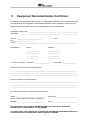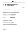
1
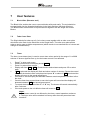
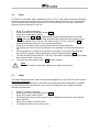
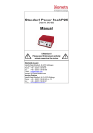
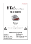
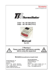
Code – No. 051-300 (230 V)
Code – No. 051-390 (115 V)
Manual
September 2010
Please read these instructions carefully
before using this apparatus!
Biometra GmbH
Rudolf-Wissell-Str. 30
D-37079 Göttingen
Postfach 1544
D-37005 Göttingen
Phone: ++49 – (0)5 51 / 50 68 6-0
Fax:
++49 – (0)5 51 / 50 68 6-66
e-mail: [email protected]
internet: http://www.biometra.de
Service Department
Rudolf-Wissell-Str. 14-16
D-37079 Göttingen
Phone: ++49 – (0)5 51 / 50 68 6-10 or -12
Fax.: ++49 – (0)5 51 / 50 68 6-11
e-mail: [email protected]
1
Contents
1
CONTENTS ....................................................................................................................1
2
SAFETY ..........................................................................................................................2
3
DELIVERY PARTS .........................................................................................................4
4
ACCESSORIES:.............................................................................................................4
5
INSTALLATION..............................................................................................................5
5.1
5.2
UNPACK AND CHECK .....................................................................................................5
INSTALLATION ...............................................................................................................5
6
OPERATION OF TB2 .....................................................................................................6
7
USER FEATURES..........................................................................................................7
7.1
7.2
7.3
7.4
7.5
7.6
7.7
7.8
8
BLOCK LIFTER (EXTRACTOR TOOL)................................................................................7
TUBE COVER PLATE ......................................................................................................7
TIMER ...........................................................................................................................7
ALARM ..........................................................................................................................8
OFFSET ........................................................................................................................8
EXTERNAL TEMPERATURE SENSOR (PROBE SELECTION) ...............................................9
DELAY START AND STOP ...............................................................................................9
CALIBRATION ..............................................................................................................10
MAINTENANCE............................................................................................................11
8.1
8.2
CLEANING ...................................................................................................................11
REPLACEMENT OF FUSES ............................................................................................11
9
SPECIFICATION ..........................................................................................................12
10
SERVICE ......................................................................................................................13
11
EQUIPMENT DECONTAMINATION CERTIFICATE....................................................14
12
NOTE FOR DISPOSAL OF ELECTRIC/ELECTRONIC WASTE .................................15
13
NOTICES ......................................................................................................................16
14
EC - DECLARATION OF CONFORMITY ....................................................................17
15
WARRANTY .................................................................................................................18
1
2
Safety
The following symbols mean:-
Caution: Read these operating instructions fully before use and pay particular
attention to sections containing this symbol.
Caution: Surfaces can become hot during use.
Caution: Instructions for handling.
Always observe the following safety precautions
Do not check the temperature by touch. Use a thermometer.
Do not touch surfaces which become hot during high temperature operation.
Use only as specified by the operating instructions, or the intrinsic protection
may be impaired.
After transport or storage in humid conditions, dry out the unit before
connecting it to the supply voltage. During drying out the intrinsic protection
may be impaired
Connect only to a power supply with a voltage corresponding to that on the
serial number label at the rear of the unit.
Connect only to a power supply which provides a safety earth (ground)
terminal.
Only use mains cable tested for connection to the electric supply
Ensure that the mains switch and power plug are easily accessible during use.
The unit must be placed on a level, non-flammable surface away from
flammable materials and ensuring that all ventilation slots in the base are clear
from obstructions.
2
Always use the Block lifter for inserting or removing a block.
Do not put any hot blocks on inflammable surfaces.
Before moving, allow to cool and disconnect at the power supply socket.
To reduce the risk of eye injury during high temperature operation, use safety
goggles or spectacles.
Use appropriate vessels / tubes for temperature required.
Ensure that the operating temperature is less than the maximum operating
temperature of your sample material.
Never fill liquid directly into the thermostat (always use blocks).
If liquid is spilt inside the unit, disconnect it from the power supply and have it
checked by a competent person.
It is the user's responsibility to carry out appropriate decontamination if
hazardous material is spilt on or inside the equipment.
Clean the unit only with a damp cloth. Do not use chemical cleaning agents.
Before using any cleaning or decontamination method except those
recommended in this manual, users should check with the Biometra Service
Department that the proposed method will not damage the equipment.
Disconnect the mains before removing the outer cover. Note there are no user
serviceable parts inside in the unit.
3
3
Delivery parts
The Biometra Thermoblock TB2 (Order No. 051-300/390) will be delivered with
block thermostat
mains cable
manual
Blocks will be delivered separately.
4
Accessories:
Order No.
Item
form of wells
Single block for tubes
(Each Block comes with 1 block lifter and 1 tube cover plate.)
051-310
30 x 0.5 ml
conical wells
051-311
70 x 0.2 ml
conical wells
051-312
24 x 1.5 ml
conical wells
051-313
24 x 2.0 ml
parallel wells
Single block for test tubes
(The block comes with 1 block lifter.)
051-315
20 x 1.3 cm deep wells
parallel wells
Single block for Falcon tubes
(Each block comes with 1 block lifter (051-316) or 2 block lifter (051-317).)
051-316
8 x 15 ml vessels
conical wells
051-317
5 x 50 ml vessels
conical wells
Single block to be used as Heating plate or dummy block
(The block comes with 1 block lifter.)
051-319
flat
without wells
Combi block (full size)
(Each block will be delivered with 2 block lifter.)
051-320
96-well microtiter plates
or 96 x 0,2 ml tubes
v-form wells
051-321
Microtiter plates with flat bottom
or microscopic slides
without wells
Combi block (full size) with lid
(for high precision temperature uniformity of the block)
051-325
96-well microtiter plates
without wells
4
additional accessories:
051-350
external Temperature Sensor for tubes ≥ 0.5 ml
051-331
051-230
tube cover plate for TB2
block lifter for TB1 and TB2
5
Installation
5.1
Unpack and Check
Unpack and carefully examine the Thermoblock TB2. Report any damage to BIOMETRA.
Save all packing material if damage is found.
Do not attempt to operate this device if physical damage is present.
If you would like to send the unit back to us, please read the return instructions.
5.2
Installation
Connect the mains cable with the IEC socket at the back of the unit.
Insert 1 Combi block or 2 Single blocks. Use the block lifter provided.
Attention:
Please handle the blocks carefully, do not let them drop. If they get damaged
this can affect the temperature.
Please always insert all blocks in the unit - even if you only use one – only
then good temperature stability is guaranteed.
Switch on the system. The ON/OFF Switch is at the front of the unit.
5
6
Operation of TB2
Display
Mains inlet
Removable blocks
Heater indicator
Control knob
Fault indicator
Mains switch
(S)elect button
(F)unction button
1.
2.
3.
4.
5.
6.
Fit the desired blocks (2 Single blocks or 1 Combi block) into the heater well. Ensure
that the heater bed and the bottom of the blocks are clean in order to ensure good
thermal contact between heater and blocks resulting in optimal temperature control
performance.
Turn the unit on by pressing the mains switch on the front of the unit. The display will
illuminate showing the current temperature of the block.
Press the “S” button and adjust the set temperature using the knob. Press “S” to select
the temperature or press “F” to exit without changing the value.
The block heater will now begin to heat the blocks. The heater light will illuminate
continuously during the heating phase but will begin to flash when the set temperature
is approached.
Allow the block(s) to stabilise at the set temperature before use.
To turn unit off, press the mains switch on the front. The set temperature will be stored
in memory. Allow unit to cool before completing any maintenance.
Notes:
If the processor detects an error in heating the fault light will illuminate, the
buzzer will beep and the display will flash -ot-. To reset this fault; switch the unit
off and on. If the fault re-occurs contact your local service agent.
6
7
User features
7.1
Block Lifter (Extractor tool)
The Block Lifter enables the user to remove blocks safely and easily. The tool should be
screwed tightly into the threaded hole/holes in the block and then the block lifted out.
The Block Lifters are delivered in required amount together with the Single and Combi
Blocks.
7.2
Tube Cover Plate
The Single blocks for tubes up to 2.0 ml volume come together with an tube cover plate
which has to be fixed via the block lifter to the Single block. The tube cover plate avoids
tubes to spring open at higher temperatures (which results in uncontrolled loss of volume and
change of concentration).
7.3
Timer
The timer (count down timer) is used to count down a time period in the range of 1 to 9999
minutes. A buzzer signifies time up, but the heater control is not affected.
1
2
3
4
5
6
7
8
9
Press F to enter main menu.
Rotate control knob until display shows CLOC.
Press S to select timer control.
Display will show ON or OFF. Rotate knob to desired state and press “S” to select
state.
If ON is selected the display will flash and show number of minutes. Rotate the control
knob until the desired value is displayed and press “S” to select. If OFF is selected the
display will return to the actual temperature.
If the timer is set the display will alternate between actual temperature and time left on
the timer.
Once the timer has counted down to zero the buzzer will sound and the display will
alternate between END and actual temperature1.
To cancel the buzzer press either “F” or “S” key. The buzzer will cancel automatically
after 5 minutes.
If the main power to the unit fails the timer will revert to OFF 2.
Notes:
1. The heater control is not affected by the timer, normal operation continues.
2. The timer value will be retained in memory after the main power has been
turned off.
7
7.4
Alarm
The alarm is a deviation alarm, settable from 0.5 to 10 ºC. If the actual temperature deviates
from the set point by more than the value selected the alarm will sound. It is only activated
once the actual value has been within ± 0.2 ºC of the set value for 2 minutes. It does not
affect the normal operation of the unit.
1
2
3
4
5
6
7
8
9
10
Press “F” to enter main menu.
Rotate control knob until display shows ALAr.
Press “S” to select alarm control.
Display will show ON or OFF. Rotate knob to desired state and press S to select.
If ON is selected the display will flash and show the current set value. Rotate control
knob until desired value is shown. (The alarm limit is ± 0.5oC to ±10.0oC) If OFF is
selected the display will return to the actual temperature.
Press “S” to set alarm state once the desired value has been selected.
The display will return to actual temperature. No indication is given that the alarm is
set.
If the temperature is outside the limit set for more than 10 seconds, the buzzer will
sound and the display will alternate between actual temperature and -AL-.
To reset the alarm press either “F” or “S” key. If the alarm conditions still exist the alarm
will re-activate after 10 seconds.
To disable the alarm feature select OFF at point 4 above.
Note:
The alarm value and set state condition are retained in memory.
7.5
Offset
The offset feature allows the user to change the temperature by up to ±2 ºC in order to allow
single point calibration.
The offset adjustment should be used if work at a single isothermal temperature is wanted.
This allows to pull the temperature in very close to the absolute value using a traceable
reference thermometer.
1
2
3
4
5
6
Press “F” to enter main menu.
Rotate control knob until display shows Oset.
Press “S” to select offset control.
The display will flash and show current value. Rotate the control knob until desired
value is shown.
Press “S” to confirm the offset value.
To cancel the offset, set the value to 0.0.
8
7.6
External Temperature Sensor (Probe Selection)
By using the optional external temperature sensor, it is possible to control the temperature of
the block directly.
Put the external temperature sensor into an tube with minimum 0,5 ml volume. Put the
sensor through an whole in the lid of the tube. Fill the tube with oil or an liquid close to the
liquid used in the tubes. Fill up the tube minimum up to hight of the sample or fill up to
maximum and seal.
Ensure the tube is in contact with the block, failure to do so will result in the temperature
exceeding the set point.
To select the external temperature sensor, complete the following procedure:
1
2
3
4
5
6
Press “F” to enter main menu.
Rotate control knob until display shows prOb.
Press “S” to select probe selection.
The display will show which probe type is currently selected. Int for internal and out for
external.
Rotate the control knob until the desired probe is shown.
Press “S” to select the desired probe.
Notes:
The external probe should be plugged in before it is selected. If the probe is not
connected to the unit or disconnected the message Err2 will be displayed.
If a difference of 30°C or more is detected between the internal and external
probe then Err3 will be displayed.
7.7
Delay Start and Stop
The delay start and stop provides a means of turning the heater control on or off after a
specified period of time.
1
2
3
4
5
6
7
Press “F” to enter main menu.
Rotate control knob until display shows deL.
Press “S” to select delay control.
Display will show ON or OFF, rotate knob to desired state. Press “S” to select state.
If ON is selected the display will show either strt (delayed start) or StOp (delayed
stop). Using the control knob select which type of delay is required.
Press “S” to select.
The display will flash and show the number of minutes delay. Rotate the control knob
until the desired value is displayed and press S to select.
Notes:
During delayed start the display will alternate between STRT and the actual
temperature.
During delayed stop the unit will continue to respond as normal. Once the
delayed period has expired the temperature control will be turned off and the
display will alternate between stop and the actual temperature. To return to
normal operation press either the “S” or “F” keys.
9
7.8
Calibration
The calibration procedure allows the user to calibrate the unit over a wide temperature range.
A calibrated thermometer will be required to measure the temperature of the block. The
adjusted readings entered must be within ±3ºC of the original reading.
1
2
3
4
5
6
7
8
9
10
11
12
13
14
15
16
17
18
19
20
21
22
Set the temperature of the unit to 35°C in the normal manner and allow the unit to
stabilise.
Press “F” to enter main menu.
Rotate control knob until display shows CaL.
Press “S” to select calibration.
The display will show PASS for one second then O001. Rotate to a value of 0004 and
press “S” to select.
Rotate the control knob until the display shows LCAL. Press “S” to select.
The display will show the current temperature value. Using the control knob change
the value to match that of the calibrated thermometer.
Press “S” to select the new value. The display will revert to the non-adjusted actual
temperature.
Set the temperature of the unit to 75°C and allow the unit to stabilise.
Press “F” to enter main menu.
Rotate control knob until display shows CaL.
Press “S” to select calibration.
The display will show PASS for one second then O001. Rotate to a value of 0004 and
press “S” to select.
Rotate the control knob until the display shows HCAL. Press “S” to select.
The display will show the current temperature value. Using the control knob change the
value to match that of the calibrated thermometer.
Press “S” to select the new value. The display will revert to the non-adjusted actual
temperature.
Press “F” to enter main menu.
Rotate control knob until display shows CaL.
Press “S” to select calibration.
The display will show PASS for one second then O001. Rotate to a value of 0004 and
press “S” to select.
Rotate the control knob until the display shows set. Press “S” to select.
The display will now display the actual adjusted temperature using the calibration
values entered.
To return to factory settings complete the following:
1
2
3
4
5
Press “F” to enter main menu.
Rotate control knob until display shows CaL.
Press “S” to select calibration.
The display will show PASS for one second then O001. Rotate to a value of 0004 and
press “S” to select.
Rotate the control knob until the display shows rFd. Press “S” to select.
10
8
Maintenance
All products covered in this manual are designed to comply with IEC61010-1 and can be
flash tested. As they are fitted with radio frequency interference suppressers it is
recommended that only a D.C. test be performed.
No other routine service is required.
8.1
Cleaning
The case can be cleaned with a damp cloth after disconnection. Do not use solvents or
abrasives.
Attention:
Disconnect from the power supply socket.
Before using any decontamination or cleaning method except that recommended, check with
our Service Department that the proposed method will not damage the equipment.
8.2
1.
2.
3.
4.
Replacement of fuses
Remove the IEC power plug from the rear of the unit.
Pull out the fuse drawer by applying leverage in recess.
Remove the fuse from the holder.
Check and replace with the correct fuse if necessary.
The fuse should be ceramic quick acting, rated:
230Vac
F2.0 A
115Vac
F3.15AF
11
9
Specification
Minimum setting temperature
Max. Temperature
15°C
130°C
Stability at 37°C within block
Uniformity at 37°C within block
± 0.1°C
± 0.1°C
Number of blocks
1 (Combi Block) or 2 (Single Blocks)
Setting resolution
Display resolution
0.1°C
0.1°C
Heat up time 25°C to 100°C
15 minutes
Width x height
200 mm x 100 mm
Power
220 - 240V / 50 - 60hz or 110 - 120V / 50 - 60hz
140W
Internal thermal fuse
(which operates at a temperature of 230°C)
Overtemperature protection
Environment operating range
10°C to 35°C
80% max relative humidity
12
10
Service
Should you have any problems with this unit, please contact our service department or your
local Biometra dealer:
Biometra
GmbH
Service Department
Rudolf-Wissell-Straße 14 - 16
D-37079 Göttingen
Phone:
++49 – (0)5 51 / 50 68 6 – 10 or -12
Fax:
++49 – (0)5 51 / 50 68 6 – 11
e-mail:
[email protected]
If you would like to send the unit back to us, please read the following return
instructions.
Instructions for return shipment
•
•
•
•
Return only defective devices. Please contact the Technical Service Department at
Biometra (Tel.-No.: 0551 / 50 68 6 – 10 or -12) to get an RAN number.
Use the original box or a similarly sturdy one.
Label the outside of the box with “CAUTION! SENSITIVE INSTRUMENT!” and the RAN
number sticker. Deliveries without RAN number can not be accepted!
Please enclose a precise description of the fault, which also reveals during which
procedures the fault occurred, if possible.
Important:
Clean all parts of the instrument from residues, and of biologically dangerous,
chemical and radioactive contaminants. Please include a written
confirmation that the device is free of biologically dangerous and radioactive
contaminants in each shipment. If the device is contaminated, it is possible
that Biometra will be forced to refuse to accept the device.
•
•
The sender of the repair order will be held liable for possible losses resulting from
insufficient decontamination of the device.
Please enclose a note which contains the following:
a) Sender’s name and address,
b) Name of a contact person for further inquiries with telephone number.
13
11
Equipment Decontamination Certificate
To enable us to comply with german law (i.e. §§28 and 80 StrlSchV, §17 GefStoffV and §19
ChemG) and to avoid exposure to hazardous materials during handling or repair, will you
please complete this form, prior to the equipment leaving your laboratory
COMPANY / INSTITUTE _________________________________________________________
ADDRESS
_________________________________________________________
TEL NO ______________________________
FAX
NO__________________________
E-MAIL _______________________________________________________________________
EQUIPMENT
If on loan / evaluation
Model
Serial No
______________
______________
______________
______________
______________
______________
______________
______________
Start Date: __________________
Finish Date __________________
Hazardous materials used with this equipment
_______________________________________________________________________________
_______________________________________________________________________________
_______________________________________________________________________________
Method of cleaning / decontamination
_______________________________________________________________________________
_______________________________________________________________________________
_______________________________________________________________________________
The equipment has been cleaned and decontaminated:
NAME ___________________________________
POSITION _________________________
(HEAD OF DIV./ DEP./ INSTITUTE / COMPANY)
SIGNED __________________________________
DATE _____________________________
PLEASE RETURN THIS FORM TO BIOMETRA GMBH OR YOUR LOCAL BIOMETRA
DISTRIBUTOR TOGETHER WITH THE EQUIPMENT.
PLEASE ATTACH THIS CERTIFICATE OUTSIDE THE PACKAGING. INSTRUMENTS WITHOUT
THIS CERTIFICATE ATTACHED WILL BE RETURNED TO SENDER.
14
12
Note for Disposal of Electric/Electronic Waste
This symbol (the crossed-out wheelie bin) means, that this product should be
brought to the return systems and/or separate systems available to end-users
according to yours country regulations, when this product has reached the end
of its lifetime!
For details, please contact your local distributor!
This symbol applies only to the countries within the EEA*.
*EEA = European Economics Area, comprising all EU-members plus Norway, Iceland
and Liechtenstein.
15
13
Notices
_________________________________________________________________________________
_________________________________________________________________________________
_________________________________________________________________________________
_________________________________________________________________________________
_________________________________________________________________________________
_________________________________________________________________________________
_________________________________________________________________________________
_________________________________________________________________________________
_________________________________________________________________________________
_________________________________________________________________________________
_________________________________________________________________________________
_________________________________________________________________________________
_________________________________________________________________________________
_________________________________________________________________________________
_________________________________________________________________________________
_________________________________________________________________________________
_________________________________________________________________________________
_________________________________________________________________________________
_________________________________________________________________________________
_________________________________________________________________________________
_________________________________________________________________________________
_________________________________________________________________________________
_________________________________________________________________________________
_________________________________________________________________________________
_________________________________________________________________________________
_________________________________________________________________________________
_________________________________________________________________________________
_________________________________________________________________________________
_
16
14
EC - Declaration of Conformity
EU - Konformitätserklärung
July 2006
im Sinne der EG-Richtlinie über elektrische Betriebsmittel zur Verwendung innerhalb bestimmter
Spannungsgrenzen 73/23/EWG
following the EC directive about electrical equipment for use within certain limits of voltage 73/23/EEC
und / and
im Sinne der EG-Richtlinie für die elektromagnetische Verträglichkeit 89/336/EWG.
following the EC directive about the electromagnetic compatibility 89/336/EEC.
Hiermit erklären wir, dass folgender Blockthermostat,
Herewith we declare that the following Thermoblock,
Typ / type:
Best.-Nr. / Order No.
Thermoblock TB2
051-300 (230 V), 051-390 (115 V)
den grundlegenden Anforderungen der
corresponds to the basic requirements of
EG-Niederspannungsrichtlinie 73/23 EWG und der
EC low voltage directive 73/23 EEC and the
EG-Richtlinie über die elektromagnetische Verträglichkeit 89/336 EWG entsprechen.
EC directive about the electromagnetic compatibility 89/336/EEC.
Dr. Jürgen Otte
Quality Manager
17
15
Warranty
This laboratory instrument is produced with the highest practical standards of materials,
workmanship, and design. The design and manufacture of parts have been conceived with
one purpose - to produce units which will give satisfactory service.
Biometra GmbH guarantees this unit to be free from defects in materials or workmanship
under normal use or service for 24 month from date of shipment.
If, during this time, this unit proves defective in materials or workmanship, Biometra GmbH
will repair or replace it free of charge if returned to us prepaid.
This guarantee does not cover damage in transit, damage caused by carelessness, misuse
or neglect, or unsatisfactory performance as a result of conditions beyond our control; or
consequential losses as a result of failure of our product.
Biometra GmbH
Rudolf-Wissell-Str. 30
D-37079 Göttingen
Postfach 1544
D-37005 Göttingen
Phone: ++49 – (0)5 51 / 50 68 6-0
Fax:
++49 – (0)5 51 / 50 68 6-66
e-mail: [email protected]
internet: http://www.biometra.de
Service Department
Rudolf-Wissell-Str. 14-16
D-37079 Göttingen
Phone: ++49 – (0)5 51 / 50 68 6-10 or -12
Fax.: ++49 – (0)5 51 / 50 68 6-11
e-mail: [email protected]
18