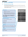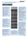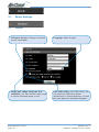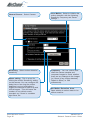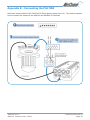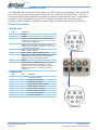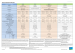
1
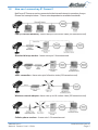
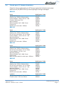
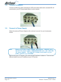
Firmware Rev. 2.32
Contents
1. Introduction ........................................................................................................... 4
1.1
1.2
2.
2.1
2.2
What is an IP Camera? ............................................................................. 4
How can I connect my IP Camera? ........................................................... 5
Physical Connections ............................................................................... 6
Rear Panel ................................................................................................ 6
Check your IP Camera Inventory ............................................................... 7
3. Installation ............................................................................................................ 8
3.1
3.2
3.3
3.4
3.5
3.6
3.7
3.8
IP Camera Installation Procedure ............................................................ 8
Connecting a CCTV Camera to the NS4120 ............................................ 9
Mounting the NetComm IP Camera ......................................................... 9
Connect to Network ................................................................................. 10
Connect to Power Supply ........................................................................ 10
Assign IP Address by ARP ....................................................................... 11
Assign IP by IP Installer ........................................................................... 13
Focusing Your Camera ........................................................................... 15
4. IP Camera Home Page ...................................................................................... 16
4.1
Browsing Video Home Page ................................................................... 16
5. IP Camera Configuration Page .......................................................................... 17
5.1
5.2
5.3
5.4
5.5
Server Settings ........................................................................................ 18
Network Settings ..................................................................................... 22
I/O Configuration ..................................................................................... 27
Video ........................................................................................................ 30
Event Manager ......................................................................................... 35
Appendix A - Upgrading the Firmware ...................................................................... 39
Obtain the firmware (flash.bin) ........................................................................... 39
IMPORTANT! (Read before proceeding) ............................................................ 39
Upgrade procedure via FTP ............................................................................... 39
Appendix B - Customise the Web GUI ..................................................................... 41
Appendix C - Configuring your Camera to for remote Access via the Internet ........ 44
Network topology ................................................................................................ 44
Ports and IP address overview ........................................................................... 45
Conventions ........................................................................................................ 45
Configuring your cameras .................................................................................. 45
Configuring Port forwarding on the Router ........................................................ 46
Viewing the Cameras from the Internet ............................................................. 46
Security ................................................................................................................ 47
www.netcomm.com.au
Page 2
YML645 Rev 2
Network Camera User’s Guide
Appendix D - Emergency Factory Default ................................................................. 48
Appendix E - Connecting the PIH-7000 ................................................................... 49
Appendix F - Trouble Shooting ................................................................................. 50
Appendix G - I/O & COM port Connectors ................................................................ 51
G.1
NS4120 .................................................................................................... 51
GPIO Terminal Block ........................................................................................... 51
G.2
NetComm NS4000/4100/4240 ............................................................... 52
Pinout information .............................................................................................. 52
CS mount adjustment ........................................................................................ 53
Appendix H - Lenses Replacement ......................................................................... 53
Fitting a Lens ...................................................................................................... 53
Appendix I - Specifications ....................................................................................... 54
Registering your NetComm Product ........................................................................ 55
Contact Information ............................................................................................ 55
Trademarks and Notices .................................................................................... 55
Product Warranty ................................................................................................. 56
Limitations of Warranty ....................................................................................... 56
Warranty Registration Form ............................................................................... 57
YML645 Rev 2
Network Camera User’s Guide
www.netcomm.com.au
Page 3
1.
Introduction
1.1
What is an IP Camera?
The NetComm IP Cameras are designed around a versatile S.M.A.R.T camera platform.
Surveillance Monitoring and Risk management Technology. Under the hood is an
ingeniously embedded web and ftp server with a robust UNIX-like operating system,
making our IP Cameras the obvious solution for sites requiring unfaltering 24/7
surveillance.
Installing an IP Camera; connect it to the Internet or your company network, and the
NetComm IP camera becomes an efficient on-line solution for live, cost-effective local or
remote monitoring and surveillance applications. Use a standard web browser to
access live video streams and for remote configuration.
You can set the IP cameras up to record images on 'event triggering' using either the inbuilt video motion detector or by connecting external sensor alarms. The simple user
interface allows you to quickly configure the camera to send emails with image
attachment and sms to alert you should an event occurs. Live video can be recorded to
a hard disk locally or remotely.
Powerful features include on-board image processing, HTTP web serving, FTP file
transfer, JPEG compression,
SMTP email, remote sensor
connectivity, event triggers
internal and external, with
excellent WAN and wireless
support using the NetComm
range of wireless products.
The NetComm IP Cameras are
rich in feature set and solid
performers in harsh
environments.
NetComm's IP Camera range
are the obvious choice for a
wide range of sites requiring
monitoring and surveillance
such as banks, office
buildings, retail outlets,
warehouses and hotels.
www.netcomm.com.au
Page 4
YML645 Rev 2
Network Camera User’s Guide
1.2
How can I connect my IP Camera?
NetComm IP Cameras can be connected to the Internet/intranet in a number of ways.
Please find examples below. *Frame rates dependant on available bandwidth.
LAN (Local Area Network) - frame rate up to full motion video (25 frames/second)
Standard dial-up modem - frame rate up to 2 frames/second.
xDSL connection - frame rate up to full motion video (25 frames/second)
Wireless network adapter- frame rate up to full motion video (25 frames/second)
Cellular phone modem - frame rate 1-5 frames/second.
YML645 Rev 2
Network Camera User’s Guide
www.netcomm.com.au
Page 5
2.
Physical Connections
2.1
Rear Panel
GPIO Port (4 relay inputs , 1 output)
Connect alarm sensors, PIR’s, motion
detectors, switches etc for event
triggering. You can connect up to four
triggering devices to the 4 relay inputs.
The relay output enables the camera to
control external electronic devices such
as boom gates, fences, lights etc. (refer
to appendix F)
DIP Switch 2
(Applies to NS4120 only) When
connecting an analogue CCTV
camera to the NS4120 (refer to
Appendix F).
BNC Port/s (NS4120/4240)
The NS4120 (pictured) has 1 video
output port for recording to a VCR
or connection to an analogue TV
monitor. The NS4240 has 1 BNC
output and 3 BNC input ports
allowing you to connect up to the 3
CCTV cameras.
Network connection
Standard Ethernet port for network
connection.
PWR LED
Power On: constant red.
Factory default: blinking orange (i.e.
red mixed with green.
Com Port
For modem connection. NS4120
(pictured) has an RS-232 com port. The
NS4000/4100/4240 have a 9-pin mini DIN
port and ship with an RS-232 converter.
www.netcomm.com.au
Page 6
NETWORK LED
Network link (connected): Constant
red.
Network activity: Blinking red.
Data sent out from server: Blinking
green.
Network disconnected: Constant
slow blinking green.
Upgrading firmware: Constant
blinking orange from slow to fast.
YML645 Rev 2
Network Camera User’s Guide
2.2
Check your IP Camera Inventory
Check the items supplied with your IP Camera against the list below and contact
NetComm on (02) 9424 2000 if you find anything is missing or damaged.
NS4000
Item
NS4000 IP Camera
Packing box 309(L)*276(W)*80(H)
Power adapter 14V/13.8V AC 1.0A
Fixed iris lens-6mm F2.0
Mount bracket
Ethernet Cable Cat5 1.0Mtr Cross
Product CD
MiniDin to D-sub cable - 300mm
NetComm Code
NS4000
PM843
WW236
MS646
HW303
CB233
CRS771
CB234
NS4100
Item
NS4100 IP Camera
Packing box 309(L)*276(W)*80(H)
DC-Iris vari-focal lens F1.4 3.2-10mm
Power adapter 14V/13.8V AC 1.0A
Mounting bracket
Ethernet Cable Cat5 1.0Mtr Cross
Product CD
MiniDin to D-sub cable - 300mm
NetComm Code
NS4100
PM843
MS645
WW236
HW303
CB233
CRS771
CB234
NS4120
Item
NS4120 IP Camera
Packing box 309(L)*276(W)*80(H)
DC-Iris vari-focal lens F1.4 3.2-10mm
Power adapter 12V DC 1.0A
Mounting bracket
Ethernet Cable Cat5 1.0Mtr Cross
Product CD
BNC to GPIO cable for video input - 200mm
NetComm Code
NS4120
PM843
MS645
WW235
HW303
CB233
CRS771
CB232
NS4240
Item
NS4240 IP Camera
Packing box 309(L)*276(W)*80(H)
DC-Iris vari-focal lens F1.4 3.2-10mm
Power adapter 14V/13.8V AC 1.0A
Mounting bracket
Ethernet Cable Cat5 1.0Mtr Cross
Product CD
MiniDin to D-sub cable - 300mm
NetComm Code
NS4240
PM843
MS645
WW236
HW303
CB233
CRS771
CB234
Lenses
DC-Iris vari-focal lens F1.4 3.2-10mm
Fixed Iris lens F1.8 Lens 6.0mm
NetComm Code
MS645
MS646
YML645 Rev 2
Network Camera User’s Guide
www.netcomm.com.au
Page 7
3.
Installation
3.1
IP Camera Installation Procedure
Important note: If you will be
installing a NetComm IP
Camera in an outdoor
application, it must be
housed in a weatherproof
enclosure. The IP Camera
must also be equipped
with a DC-Iris lens. If these
conditions are not met
warranty will be void. The
NetComm NS4100/4120/4240
NetComm Outdoor Camera
ship with a high quality DCHousing MSHTH-S3
Iris fitted. NetComm have
an all-purpose industrial grade weatherproof housing.
www.netcomm.com.au
Page 8
YML645 Rev 2
Network Camera User’s Guide
3.2
Connecting a CCTV Camera to the NS4120
You can connect additional CCTV cameras to the NS4120 (1 CCTV camera) and
NS4240 (up to 3 CCTV cameras). This section outlines the installation procedure for
connecting a CCTV camera to the NS4120. (Note: the procedure for connecting
analogue cameras to the NS4240 is similar, except you are connecting the cameras to
the BNC port rather than the GPIO pins.)
Connect the GPIO to BNC cable (ships
with the NS4120) to pins 14 and 15
(see Appendix G for more details)
Set the dip switches to - 1 off & 2 on, as
pictured.
Go to
3.3
Select Save Changes and then Reboot System.
Mounting the NetComm IP Camera
The NetComm IP Camera has threaded screw holes on both the top and bottom
surfaces of the unit for mounting the stand assembly. So you can quickly and easily
mount your IP Camera on a desktop, a wall, or ceiling.
YML645 Rev 2
Network Camera User’s Guide
www.netcomm.com.au
Page 9
3.4
Connect to Network
Connect an Ethernet cable (twisted pair CAT5 terminated cable with a standard RJ-45
connector) to your IP Camera and attach it to the network.
3.5
Connect to Power Supply
Attach the external Power Adaptor to the unit and connect it to your local power
socket.
Note:
Ensure you power supply adapter specification. NS4120 uses a
'DC 12V 1A' power supply. NS4000/4100/4240 use a 'AC 14V/13.8V
1A' power supply. The Input AC Voltage must match to your
power system, e.g. 110V/220V.
Before using your IP Camera, you must set the IP address in advance. There are two
different ways to set an IP address to your IP Camera.
www.netcomm.com.au
Page 10
YML645 Rev 2
Network Camera User’s Guide
3.6
Assign IP Address by ARP
Important Note: The default IP address
of ALL NetComm IP Cameras is
192.168.0.200
Note before IP assignment:
■
Make sure the IP Camera is powered on and connected to the
network correctly.
■
Obtain a unique IP address from your network administrator.
■
MAC Address: Each IP Camera has a unique Ethernet address
(MAC address), which is recorded as a 12 digit MAC number
labeled on the bottom of IP Camera (e.g. 000429xxxxxx).
■
The setup example uses a PC with an IP address of 192.168.0.1 and
an IP address of 192.168.0.200 for the IP Camera - of which the MAC
address is 000429000150. (Always consult your network
administrator before assigning an IP address.)
■
The IP address assigned to the IP Camera shall be the same IP
domain (presented as the same subnet mask) as the PC IP
address. In this example, the PC IP address is 192.168.0.1 and the
IP Camera is 192.168.0.200, so the subnet mask shall be
255.255.255.0. If the PC subnet mask is 255.255.255.128 or higher,
then the domain cannot cover 192.168.0.200, so the setting will not
be effective.
■
For a quick and easy install, an IP Installer Wizard is provided on
the product CD. Refer to section 3.6 for more information.
1. In Windows, open a DOS window.
■ Enter DOS by Start, Run, enter cmd and click OK.
2. Ensure the IP address assigned to the IP Camera is not already being used on the
network.
■ In the DOS window, type <ping 192.168.0.200> Press enter. You will then get
the following on your screen.
C:\>ping 192.168.0.200
Pinging 192.168.0.200 with 32 bytes of data:
Request
Request
Request
Request
timed
timed
timed
timed
out.
out.
out.
out.
Ping statistNC for 192.168.0.200:
Packets: Sent = 4, Received = 0, Lost = 4 (100% loss),
Approximate round trip times in milli-seconds:
Minimum = 0ms, Maximum = 0ms, Average = 0ms
C:\>
YML645 Rev 2
Network Camera User’s Guide
www.netcomm.com.au
Page 11
3. Enter command <arp -s [IP Camera IP Address] [IP Camera MAC Address]>
■ In DOS, enter "arp -s 192.168.0.200 00-04-29-00-01-50"
4. Enter command <ping -t [IP Camera IP Address]> you will get constant reply after
3~4 timeouts, then press CTRL-C to exit pinging.
■ In DOS, enter "ping -t 192.168.0.200"
C:\>arp -s 192.168.0.200 00-04-29-00-01-50
C:\>ping -t 192.168.0.200
Pinging 192.168.0.200 with 32 bytes of data:
Request timed out.
Request timed out.
Request timed out.
Reply from 192.168.0.200:
Reply from 192.168.0.200:
Reply from 192.168.0.200:
Reply from 192.168.0.200:
bytes=32
bytes=32
bytes=32
bytes=32
time=5ms
time=4ms
time=4ms
time=4ms
TTL=255
TTL=255
TTL=255
TTL=255
Ping statistNC for 192.168.0.200:
Packets: Sent = 7, Received = 4, Lost = 3 (42% loss),
Approximate round trip times in milli-seconds:
Minimum = 4ms, Maximum = 5ms, Average = 2ms
Control-C
C:\>
5. Complete settings and verify the installation. Then, open your web browser and
enter the IP address in the Location/Address field. The IP Camera video home page
will be opened.
www.netcomm.com.au
Page 12
YML645 Rev 2
Network Camera User’s Guide
3.7
Assign IP by IP Installer
NETCOMM IP Installer is a Windows 98/ME/NT/2000/XP program. The IP Installer provides
an easier way for setting IP addresses and network configurations for the IP Camera.
Using this tool, you can easily set multiple IP Cameras at the same time with the batch
setting function. By utilizing IP Installer, the setting process is simplified. IP installer can
not only save all the configurations of the IP Cameras as backup, but also restore the
previous configurations.
3.7.1 Execute IP Installer
Double click the mouse left button on the IP Installer icon, found in your product CD.
The NETCOMM IP Installer form is displayed on the screen.
1
Click this button to
search for any Network
Cameras on the LAN.
2
List all the NetComm
Network Cameras on the
LAN.
3.7.2 Preparation before IP Assignment:
■ Always consult your network administrator before assigning an IP address to your
server.
■ Make sure the NetComm IP Cameras are powered on and correctly connected to the
network.
■ MAC Address: Each NetComm IP Camera has a unique MAC address shown on the
bottom of the IP Camera, it has 12 digits (e.g. 000429-XXXXXX).
YML645 Rev 2
Network Camera User’s Guide
www.netcomm.com.au
Page 13
3.7.3 Assigning an IP Address to the IP Cameras
Select the MAC Address of your NetComm IP Camera in the list. The MAC Address is
found underneath the NetComm IP Camera. And click the menu bar View/Property to
open the Property Page for the selected item. After filling in the properties, click the OK
button to submit the settings for the camera and the settings will be activated
immediately.
www.netcomm.com.au
Page 14
YML645 Rev 2
Network Camera User’s Guide
3.7.4 Verify the IP Address and Open the Home Page
To access the Home Page of the selected camera, run the View/Open Web on the menu
bar. If you find your browser is opened and automatically connected to the IP Camera
Home Page, it means you've assigned an IP Address to the unit successfully. Now you
can close the IP Installer and start to use your NetComm IP Cameras.
3.7.5 Verify and Complete the Installation from Your Browser
Start your browser and enter the IP Address of your IP Camera in the location /address
field of your web browser.
3.8
Focusing Your Camera
Please refer to Appendix H - Lense Replacement.
YML645 Rev 2
Network Camera User’s Guide
www.netcomm.com.au
Page 15
4.
IP Camera Home Page
4.1
Browsing Video Home Page
Enter the default IP address of the IP Camera being, 192.168.0.200 in the address field
of your web browser. Press enter/go.
The home page of the IP Camera will open and you will see a navigational bar on the left
hand side of the home page:
Video Source
1. Represents the video streaming from the
NetComm IP Camera
2. Additional camera - this represents the
image streaming from the CCTV camera
attached to the NetComm IP Camera.
Note: NS4120 connects 1 additional CCTV
camera, NS4240 connects 3 additional
CCTV cameras.
Video Size Selection
1x 176 x 144 (resolution/ pixels)
2x 352 x 288
4x 704 x 576
Resolution size will affect the frame rate of the
IP Camera.
Snapshot
Takes a picture from the viewing video. Still
image can then be sent as an attachment via
email.
Configure
Will take you into the Configuration page of
the IP Camera.
www.netcomm.com.au
Page 16
YML645 Rev 2
Network Camera User’s Guide
5.
IP Camera Configuration Page
Server Configurations
Network Configurations
General: To input general
information about the IP
Camera.
User: Create and delete
users and passwords.
Clock: Set the Date and
Time.
System: Provide
commands for resetting
the factory default
settings, restarting the
system, and saving
configurations to the flash
memory.
General: To assign an IP
Address and configure the
relevant network
parameters to the IP
Camera.
DHCP: DHCP (Dynamic Host
Configuration Protocol) is a
protocol that lets network
administrators centrally
manage and automate the
assignment of Internet
Protocol (IP) addresses.
DDNS: The DDNS (Dynamic
Domain Name Service) is
used to access the IP
CAMERA with an easy to
remember name such as
http://
demo.ddns.netcomm.com.au
instead of http://
61.220.235.172.
I/O Configurations
Serial: Select the
operational modes for the
COM1 and COM2.
PTZ Device: Select the
camera driver that
corresponds to your PTZ
device and control the PTZ
device.
GPIO: General Purpose
Input / Output. These are
for event triggers and
actions.
Event Configurations
Video Configurations
Time Stamp: Show time
and text on the video.
Quality: Adjust the video
quality and compression
level.
CCD: Adjust the built-in
CCD module status
YML645 Rev 2
Network Camera User’s Guide
Voice Configurations
Voice Adjust: Adjust the
Line In Gain, Line Out Gain,
and Voice Activity
Detection parameters, etc.
Motion: Create and enable
the video motion detection
feature. For triggering and
recording on an event.
Use Script Edit to drill down
and fully configure the
video motion detection
settings.
Script Edit: The Script
Editor offers greater level
of flexibility for customizing
the application specific to
their user needs. Using the
on-line help as a reference,
users can follow
the instructions to quickly
develop programming
scripts for time and/or
alarm-triggered events.
www.netcomm.com.au
Page 17
5.1
Server Settings
5.1.1 General
Firmware Version: Displays firmware
version information.
Language: Select English
Large size image using the true
resolution: You can set the Large image
to use an interlaced image, or not.
Live video using: Live video using: You
can select the ActiveX for better
performance in Internet Explorer, or select
the Java Applet for Netscape Navigator.
www.netcomm.com.au
Page 18
YML645 Rev 2
Network Camera User’s Guide
5.1.2 User Settings
Important note: the first user to be added must be given full Admin rights by
selecting Administrator; otherwise no one can access the
Administration page of the camera. If the first user added is not
given Administrator rights, you will need to reset the IP camera to
factory default.
The NetComm IP Camera provides 3- layer user security control as detailed below:
Password: Add password for
security log in and then confirm
password.
Administrator: Select this to give
user access to administration page.
Name: Add new user name for user
name login. The individual who will
have main administration rights to the
camera should be the first user to be
entered
Change Video Size: If selected,
user can change video size, if not
selected only 352 x 240 resolution is
allowed.
See Video All (factory default):
Selecting this allows any users over
Internet to access and view images
from the IP Camera.
Video Channel [1-2]: Permissions
to see the indicated video channels.
PTZ Control on Channel [1-2]:
Permissions to do PTZ control on the
indicated video channels.
Submit: click to add new user and
user profile to list. Note: When
entering "submit" for the first time, the
IP Camera will ask for a new
administrator to login in. Once adding
users, then you can choose users in
list to make modification (update), or
remove specified user.
Cancel: to abort and restart user
profile.
Once the Administrator and users have been entered, go to Configure and then click on
and "Save Changes".
Please note that the maximum display area (time & text) is 12 x 4 characters. Any text
more than 12 characters will flow onto the next line. A total of 4 lines are available. If
you enter more than 4 lines of text, it will be truncated.
YML645 Rev 2
Network Camera User’s Guide
www.netcomm.com.au
Page 19
5.1.3 Clock
A quick configure GUI to set the time and date of the IP Camera
www.netcomm.com.au
Page 20
YML645 Rev 2
Network Camera User’s Guide
5.1.4 System
Save Changes: When changing
settings in the IP Camera such as DHCP
and Image Quality you will need to select
the Save Change box to finalise the
setting changes.
Load Default: By selecting this, will
reset all the camera configurations to
their default settings.
Reboot System: Will perform a softreboot and restart the camera.
YML645 Rev 2
Network Camera User’s Guide
www.netcomm.com.au
Page 21
5.2
Network Settings
5.2.1 General Network Settings
Set your network settings for the IP Camera here.
www.netcomm.com.au
Page 22
YML645 Rev 2
Network Camera User’s Guide
5.2.2 DHCP
DHCP (Dynamic Host Configuration Protocol) is a protocol that lets network
administrators centrally manage and automate the assignment of Internet Protocol (IP)
addresses in an organization's network.
Important note: DHCP should only be enabled if you know which IP address
the IP Camera will get from the DHCP server, or if your version of
DHCP can update a DNS server, which then allows you to access
the IP Camera by name. If DHCP is enabled and you cannot access
the unit, you may have to reset it to the factory default settings
(see Appendix D) and then perform the installation again.
Note:
Once you have configured your DHCP settings, go to
, select Save Changes and then Reboot System
YML645 Rev 2
Network Camera User’s Guide
www.netcomm.com.au
Page 23
5.2.3 DDNS Settings
Selected NetComm IP Cameras support Dynamic Domain Name Service (DDNS). This
allows a camera to be addressed on the Internet by using a fully qualified domain name
(FQDN), such as http://cam1.ddns.mydomain.com.au , rather than its IP address
(61.1.1.25) which may change upon each connection to the Internet. This is most useful
when the IP Camera is connected to the internet via a dial-up, ADSL or other IP sharing
device that does not have a fix IP address.
The mechanism of the DDNS service is simple in that each IP Camera can "register" its
name, router virtual port number and current IP address on a DDNS server and the
DDNS server then responds to any DNS requests for the camera's IP address.
Setting Up a DDNS Server
Note:
The DDNS service is proprietary and will only work with NetComm
IP Camera's and servers configured with DDNS components
available from NetComm
The information here is not intended to be explicit instructions for configuring your
server or registering your server on the Internet, it is given here as a guide only.
Detailed instructions on DDNS Server installation are supplied with the DDNS
components.
System Requirements
The minimum requirements for a DDNS server are ■ Microsoft Windows 2000 Server or Microsoft Windows 2000 Advanced Server
■ Microsoft Internet Information Server (IIS)
■ Microsoft Domain Name Service (DNS)
■ Hardware to support the above services.
Installing the DDNS server
1. Ensure that each DDNS server is available via the Internet at all times and
addressed using a Fully Qualified Domain Name (FQDN).
2. Install Microsoft Windows 2000 Server or Microsoft Windows 2000 Advanced
Server with the Internet Information Server (IIS) service and Domain Name Service
(DNS) (please refer to the Microsoft Windows 2000 documentation for instructions
on installing Windows and these services correctly).
If the DDNS service is not going to be installed on a server that is not a Domain
Controller, you will need to manually set the DNS name for proper DNS resolution. To
do this, click Start -> Control Panel -> System -> Network Identification -> Properties
-> More and enter the FQDN of the server. (e.g. ddns.mydomain.com.au)
3. Set the default site web in the IIS Configuration (root web folder) and copy and
register the DDNS configuration components provided by NetComm into the root
web.
4. Once DDNS have been configured in Microsoft Windows, you may then enable the
Dynamic DNS Configuration options in each NetComm IP Camera.
www.netcomm.com.au
Page 24
YML645 Rev 2
Network Camera User’s Guide
Dynamic DNS Configuration
Dynamic DNS Activate: Click on to
activate the DDNS service.
Dynamic DNS Address: Specify
the FQDN of the DDNS server, e.g.
"ddns.mydomain.com.au"
Dynamic DNS Port: Specify the
TCP/IP port the DDNS server listens
on. The default is "80"
Update Time: Specify the
frequency, in seconds, which the
NetComm IP Camera sends updates
to the DDNS server. The default is
600 seconds (10 minutes).
DDNS message: This section
displays and messages returned
from the DDNS server. This is useful
on helping diagnosing problems if the
DDNS service is not working as
expected or the registration with the
DDNS server fails.
Router Incoming Port: Specify the
port your router is on for the DDNS
server to redirect to. This is needed in
environments where a different port
is used for incoming (Internet
requests) and outgoing (Intranet
requests). For example, if your router
listens on Internet (external) using
port 80, but the DDNS server listens
on 8000, then you must configure the
"Router Incoming Port" to 80, and
inside the NetComm IP Camera
Network settings (Network
Configuration) should set HTTP port
with 8000.
Some common messages are DDNSADDR CGI Fail: This means that the NetComm IP Camera can not communicate with
DDNS server. Check your Network Configuration settings and are correct, including
subnet mask, default gateway, and DNS information.
Already Registered: This indicates that another device has registered using the same
name. Change the registration name by changing "Server Name" under General Settings.
YML645 Rev 2
Network Camera User’s Guide
www.netcomm.com.au
Page 25
Example Configuration
Say you wish to setup a IP Camera on your Local Area Network (LAN), on IP address
192.168.0.200, and make it available on the Internet using a FQDN such as http://
demo.ddns.mydomain.com.au and your Internet connection is via a dialup ADSL router.
To accomplish this, you will need to perform the following steps1. Configure your ADSL router to allow connection to your service provider.
2. Configure the ADSL router with PPPoE enable; the LAN IP as, 192.168.0.254; and a
subnet mask of 255.255.255.0.
3. Assign the ADSL router's virtual server with service port 80 to server IP
192.168.0.200 (forwarding / NAT)
4. Configure the NetComm IP Camera with an IP address of 192.168.0.200, a subnet of
255.255.255.0, a valid DNS address, the gateway IP address of 192.168.0.254 (the
router's IP address) and the HTTP 'listen' port as port 80.
5. Configure Server Name in General Setting with "demo".
6. Configure DDNS with Activate; Address "ddns.netcomm.com"; DDNS with port 80;
Router Incoming port 80; and update time with 600 (10 minutes).
7. If you see in the DDNS message window "Success", then you can access the
camera using the FQDN of http://demo.ddns.mydomain.com.au on your browser.
www.netcomm.com.au
Page 26
YML645 Rev 2
Network Camera User’s Guide
5.3
I/O Configuration
5.3.1 Serial Port Configuration
Here you can configure the serial port mode and configure the serial port settings.
Refer to Appendix G for GPIO pin out detail.
YML645 Rev 2
Network Camera User’s Guide
www.netcomm.com.au
Page 27
5.3.2 GPIO Status (available only on NS4100/4120/4240)
Displays the GPIO (General Purpose Input / Output) status. The GPIO Terminal Block /
MINI DIN provides control signal input and output, which includes four GPIO inputs, one
GPIO relay output. See Appendix G for the detailed description.
Set the relay: The relay output is for
controlling external electrical devices
such as boom gates, lights,
mechanical doors etc. Click the relay
button to set the relay to ON or OFF.
www.netcomm.com.au
Page 28
YML645 Rev 2
Network Camera User’s Guide
5.3.3 PTZ Adjustment
Model: Select a PTZ camera from
the drop down box.
Speed: Calibrates the PTZ speed
grade from 1(slowest) to 10(fastest)
Preset Position/Name: Preset up
to 20 camera positions.
PTZ Panel: Control the PTZ devices
Zoom in/out, Pan left/right, and Tilt up/
down.
Position Name: Give the preset
positions a relevant, meaningful name
eg Warehouse, dispatch, aisle 3 etc.
YML645 Rev 2
Network Camera User’s Guide
www.netcomm.com.au
Page 29
5.4
Video
5.4.1 Time Stamp
To display time & test over the video image.
Display Time: select to display the
Time Stamp.
Display Text: select to display the
text on camera image
www.netcomm.com.au
Page 30
To change the location of Time/Text,
fill in the X and Y coordinate.
YML645 Rev 2
Network Camera User’s Guide
5.4.2 Quality (NS4100/4120/4240)
Here you can adjust the image quality of the NS4100/4120/4240. The default settings
will be suitable in most circumstances, however in some cases you will need to
configure the image settings to allow for varying light conditions. Note that increasing
quality and colour levels will decrease compression ratio and thus increase file size of
the mjpeg images.
Frame Delay: You can configure time between frames to
manage the frame rate. The unit of delay time is 10
microseconds. You can limit the output bandwidth via setting
the frame delay to do the flow control of the video stream.
When the value is set to 0, it means no limitation on the video
stream.
Click "set" and then
YML645 Rev 2
Network Camera User’s Guide
and select Save Changes.
www.netcomm.com.au
Page 31
5.4.3 Quality (NS4000)
Here you can adjust the image quality of the NS4000. The NS4000 does not have a CCD
configuration page as it has a CMOS image sensor. Full configuration for the image
settings is done at this page.
Frame Delay: You can configure time between frames to
manage the frame rate. The unit of delay time is 10
microseconds. You can limit the output bandwidth via setting the
frame delay to do the flow control of the video stream. When the
value is set to 0, it means no limitation on the video stream.
Click "set" and then
www.netcomm.com.au
Page 32
and select Save Changes.
YML645 Rev 2
Network Camera User’s Guide
5.4.4 CCD Module Settings (For 4120)
Auto Electronic Shutter: Set to
"off".
Back Light Compensation: Adjust
the light balance method. When set to
"on", it will be calculated by the center
area of video window. And when set
to "off", it will be calculated by full
video window, which could
compensate the light conditions if
center object looks too dark.
Day Night Control: Set to "on", it will
switch to black/white mode when in
low light (dark) condition automatically;
set to "off", it will always display color
video.
Note:
When using a Lens with DC-Driver Auto IRIS capabilities, you must
set AES to "off" in order to get optimal Lens performance.
YML645 Rev 2
Network Camera User’s Guide
www.netcomm.com.au
Page 33
5.4.5 CCD Module Settings (For NS4100/4240)
White Balance: White balance
allows for colour correction to deal
with differing lighting conditions.
ME/AE: Set electronic shutter speed
manually or automatically by light
condition.
I/E sync: Line lock feature. When set
to "external", the V-Sync will lock
with power line frequency. It's useful
to eliminate color-rolling effect.
Flickerless: Set to "off" position
(feature for NTSC standard which
does not apply in Australia)
www.netcomm.com.au
Page 34
Auto Gain Control: Normally "off"
with maximum 10db gain, "on" will
increase to maximum 24db. It's useful
to increase sensitivity in low-lighted
environments (set to "on"), but more
gain will produce more noise.
AES (Auto Electronic Shutter):
NS4100/4240 should be set to "off".
Note:
When using a DC-145
lens, set AES to "off" in
order to get optimal
lens performance.
BLC (Back Light Compensation):
When set to "on", the back light will be
calculated by center area of video
window; set to "off", it will be
calculated by full video window,
which will compensate the light
conditions if center object looks too
dark.
YML645 Rev 2
Network Camera User’s Guide
5.5
Event Manager
5.5.1 Motion
The NetComm IP Camera includes in-image motion detection. The target image area is
visibly represented as red coloured blocks. Use the motion detection feature to
generate an alarm whenever movement occurs in the image area. All movement outside
the defined motion detection area (i.e. area not selected as red blocks) is ignored.
To fully configure the motion detection you will need to go to
Click on Script Wizard
Select GPIO Relay
Select by motion
YML645 Rev 2
Network Camera User’s Guide
www.netcomm.com.au
Page 35
Channel Source: Select Camera
Sensitivity: Select motion detection
sensitivity
Pause setting: This is a tool for
refining the motion 'Sensitivity' setting
on the camera. You can configure the
delay time or how long the motion
detection is put on hold before it
triggers the camera to start to ftp and
record images. This will lessen the
number of non-critical events
recorded. eg. if there is a sudden
light flicker, etc.
www.netcomm.com.au
Page 36
Init a Motion: Select to initialise the
motion detection with the following
Sensitivity, Frequency and Pause
settings.
Frequency: You can control how
often the camera samples and
compares images to check whether
there are any changes to the images
(ie if there is any motion detected).
Default is 50ms (i.e. 500
milliseconds).
Set Motion Detection Area:
Open window to select areas to be
motion sensitive.
YML645 Rev 2
Network Camera User’s Guide
5.5.2 Script Editor
The NetComm IP Cameras can be used in a wide variety of applications. Using the
scripting commands within the Event Manager, you can quickly develop your own
application as required.
For example you may wish to upload images to a remote FTP server on a LAN/WAN
network to accommodate a large audience where a high volume of Web page hits is
anticipated. Or you may want to set up 'triggered recording', via motion detection or
external alarm device triggering - with uploading of pre and/or post alarm images to a
target FTP server, when in-image motion, external alarms, or time-based events occur.
You can also send e-mail alerts with a single image attached.
The scripts are easy to produce and enter --- just fill and submit a simple form within
Event Manager. Refer to the NetComm Script Edit user manual for more information
To start the Event Manager, simply click the Event icon, then an event frame will pop up.
There are two ways to enter your event script. One is to use the "Script Wizard".
Follow the prompts and it will generate and append a new script code to the edit
window. The other way is to edit the form manually and create your own script.
Note:
If you make changes in the "Event Script Edit" window, click "Save
Script" before "Start Script"; otherwise, the new changes will be
lost. Changes are not saved into permanent memory unless you
and select "Save Changes".
go to
YML645 Rev 2
Network Camera User’s Guide
www.netcomm.com.au
Page 37
Event Status: Shows the event
status, "Stop Now" or "Start Now".
Message: A window to show the
results when below command icon
pressed --- normally will show "OK",
"Parsing", "Fail", Or "Err String" which
indicates the syntax error of parsing,
and starts from the error position in the
script.
Event Auto Start when Power On:
The check box is to indicate whether
on not the current event will
automatically start up when the system
boots up.
Start Script: Will start the script
execution.
Stop Script: Stops the script
execution.
Save Script: Command to save and
parse current scripts in the "Event
Script Edit" window. If any syntax
errors are detected, the error
message, indicating the starting
position of syntax error, will be shown
in the "Message" window.
Script Wizard: Command to start the
script wizard. It allows you to create
a simple script automatically, but the
wizard supports only partial trigger
and action commands. To fully
leverage the complete functionalities
of the event script, please refer to
"Event Script Programmers Guide".
www.netcomm.com.au
Page 38
Set Motion Detection Area: In
order to activate the motion detection,
you must choose the detection area
and start the motion detection script
manually or with the script wizard.
Clear: Clears the "Event Script Edit"
window.
Help: Script Help lists the syntax of
trigger and action commands.
YML645 Rev 2
Network Camera User’s Guide
Appendix A - Upgrading the Firmware
The NetComm IP Camera firmware is stored in Flash memory. This memory is provided by a
silicon chip that, just like any other ROM device, retains data information even after power is
turned off. Flash memory is imbedded in the IP Camera because this technology allows its data
to be erased and re-written. This means that you can install firmware updates for your
cameras as soon as they become available - without having to replace any parts. New
firmware can be simply flash loaded into the NetComm IP Camera over the network.
Obtain the firmware (flash.bin)
The latest version of the IP Camera software is available free of charge from
www.netcomm.com.au
IMPORTANT! (Read before proceeding)
Note:
The IP Camera can become damaged if the updating operation is
not performed correctly. So please follow the procedures
carefully.
■ Upgrading the firmware usually takes 30 seconds, sometimes up to 10 minutes.
After starting the process, you should always wait at least 20 minutes before
power cycling the IP Camera - even if you suspect the upgrade procedure has
failed.
■ In controlled environments, flash memory upgrades provide a very safe method for
updating firmware. Note: the flash memory can become damaged if the upgrade
operation is not performed correctly. NetComm reserves the right to charge for any
repair resulting to faulty upgrading by the user.
Upgrade procedure via FTP
■ Download the newest software and unzip it into your local Driver, for example
"C:\temp". Then, confirm the "flash.bin" file exists in this directory.
■ Remove all event setting and Reset the IP Camera:
You have two ways to remove the event lists. One is to choose "Event ID" and to
use "Remove" icon on "Event" page. The other is to click the "Load Default" icon in
configurations page to reset all settings; however, it will not only delete event lists,
but also all other settings. Then click the "Reboot System" to restart the IP Camera
or enter CGI command URL
"http://<IP Camera IP address>/control?reboot=1" in your web browser.
Caution:
You must remove all event settings and reboot the IP Camera
before doing the following procedures; otherwise, some
occasional internal conflicts may endanger the Flash devices.
■ Start the FTP session and log in to the IP Camera
For example, in our case for Windows98:
■ Enter DOS by "start->Program->MS-DOS Prompt"
■ Change to the directory where the latest flash.bin exist.
■ Start ftp session by enter "ftp <IP CAMERA IP Address>
YML645 Rev 2
Network Camera User’s Guide
www.netcomm.com.au
Page 39
■ Enter "root" as USERNAME, "pass" as PASSWORD if no user in User List record. In
case any user list exists, you will have to use your administrator's USERNAME and
PASSWORD to login
■ Set FTP to binary mode using the command "bin".
■ In FTP session window, Enter "bin"
■ Upload the software into IP Camera by FTP "put" command.
■ In FTP session window, enter "put flash.bin"
■ In FTP session window, enter "bye" to quit FTP session.
■ FTP session may freeze for around 1 minute to transfer and automatically upgrade
the software. During that time, ping the IP Camera until you get a constant reply,
which means the system had completed upgrading and rebooting. Open the
browser to verify the software version been updated.
C:\temp>ftp 192.168.0.200
Connected to 192.168.0.200.
220 192.168.0.200
NETCOMM FTP server (ARM_BE - V3.0.H)
ready.
User (192.168.0.200:(none)): root
331 Password required for root.
Password:
<=enter pass as default
230 User root logged in.
ftp> bin
200 Type set to I.
ftp> put flash.bin
200 PORT command successful.
150 Opening BINARY mode data connection for flash.bin
226 Transfer complete.
ftp: 2097152 bytes sent in 10.11Seconds 207.43Kbytes/sec.
ftp> bye
221 Goodbye.
<=Quit ftp session immediately
<=if the window is frozen, please open
another dos session
C:\temp>ping -t 192.168.0.200
Pinging 192.168.0.200 with 32 bytes of data:
Request timed out.
Request timed out.
Request timed out.
Request timed out.
Request timed out.
Request timed out.
Request timed out.
Request timed out.
Reply from 192.168.0.200:
Reply from 192.168.0.200:
Reply from 192.168.0.200:
Reply from 192.168.0.200:
Reply from 192.168.0.200:
bytes=32
bytes=32
bytes=32
bytes=32
bytes=32
time=2ms
time=1ms
time<10ms
time<10ms
time<10ms
TTL=255
TTL=255
TTL=255
TTL=255
TTL=255
Ping statistics for 192.168.0.200:
Packets: Sent = 13, Received = 5, Lost = 8 (61% loss),
Approximate round trip times in milliseconds:
Minimum = 0ms, Maximum =
2ms, Average =
0ms
Control-C
C:\temp>
C:\>
www.netcomm.com.au
Page 40
YML645 Rev 2
Network Camera User’s Guide
Appendix B - Customise the Web GUI
The IP Camera's built-in Web server contents are contained in FLASH memory and may be rewritten to provide an easy way to provided a customised "home page" to suit individual
situations or integration into other Web-based services, such as a corporate Intranet or Web
page.
The update process is performed with simple FTP and Telnet functions, available from most
personal computer operating systems.
To update the "home page", we suggest you follow the procedure outlined below. Please note
however, that because the update process requires erasing existing pages and internal code,
an interruption to the update process may cause the system to fail to respond to any requests;
thereby requiring the unit to be returned for repair.
The following operations provided here are only for the experienced user.
1. Reset the NetComm IP Camera to it's default configuration.
Click the "Load Default" button on the main Configuration Window and then click
"Save Changes" button, and then "Reboot System". All video will be unavailable
during the reboot.
2. Download a back-up of the existing content.
By using an FTP client, such as Windows FTP, CuteFTP or WSFTP, connect to the
NetComm IP Camera as an camera Administrator (root by default), and download the
following folders and their contents 3.0.0/WWW:
This folder contains the main video pages including the
static HTML and JAVA applets.
3.0.0/WWW/images:
This folder contains all graphical files.
3.0.0/WWW/Admin:
This folder contains the administration code.
3.0.0/Sys:
This folder contains the system font files for the video
bitmaps.
3.0.0/public:
This folder contains the internal message files.
Note:
When you login, do not change any files on the root directory
(3.0.0), the 3.0.0/Sys folder or the 3.0.0/public folder as these files
are used by the NetComm IP Camera internally. Changing any files
in this folders will render the camera unusable.
3. Upload custom web pages
Simply upload the updated/added contents to their original location. For example, if
you wanted to replace the NetComm banner logo (NetComm.jpg) with your own
custom made logo (oem.jpg), prepare your own "oem.jpg", and then upload the
image to the 3.0.0/WWW/images folder (one additional step is required to change the
logo in that you will need to change the logo file name to oem.jpg in "Configuration>IP Camera" page.)
Any file upload files should be sent via FTP in "binary" mode.
YML645 Rev 2
Network Camera User’s Guide
www.netcomm.com.au
Page 41
4. Commit the updated contents to FLASH memory.
Close the FTP client and telnet to the camera, once again as an Administrator, and
issue the following command to start the web content update program.
Up -w
The command is case sensitive, so if you enter it incorrectly you will receive an
error message. and complete the web content updating.
After about 30 seconds, the NetComm IP Camera will restart automatically.
Important Notes:
Do not interrupt the update process. An interruption may cause
the system to fail.
The maximum overall size of content pages is around 700kb. Any
file added or updated, plus the original files (~550kb) should not
exceed this size. Any attempt to upload more than this may result
is some of the files being truncated and thereby corrupted.
The OEM.JPG image must match the existing logo's attributes, that
is, it must be a .JPG and it must be the same size.
5. Verify updated contents
After uploading your customised pages, open a web browser to verify the
contents. Make any changes required and return to the previous steps to upload
them again.
6. Save the changes to flash
Telnet to the IP Camera. And run command "Up -w" to write the complete web pages into flash.
The detailed procedures are list as below,
1. Open DOS window
2. Enter "telnet <IP Address of IP Camera>"
3. Enter "root" and "pass" as username and password
4. Enter "Up -w" to start the web content update program. The command is case
sensitive. After processing about 30 seconds, the IP Camera will restart
automatically and complete the web content updating. Now you can open the
browser to see the new web content.
5. Note: The size of the pages must be less than 700Kbytes. Any file added/updated
plus original downloaded file should not exceed this size; otherwise, some files will
be corrupted. If the corruption of any page occurs, you will have to reload the
original binary (see Appendix A - Upgrading the Software) in order to recover the
corruption.
For example, the IP Camera IP address is 192.168.0.200, then
C:\temp>telnet 192.168.0.200
C:\temp>
Telnet session çOpen Telnet session
www.netcomm.com.au
Page 42
YML645 Rev 2
Network Camera User’s Guide
Login: root
Password:
çEnter "pass" as default
Welcome to VidSvr on Telnet ...
IVS> Up -w
Upgrade WWW Pages... ç Frozen here, close and open browser
After 30 seconds to verify the
changes.
YML645 Rev 2
Network Camera User’s Guide
www.netcomm.com.au
Page 43
Appendix C - Configuring your Camera to for remote Access
via the Internet
The NetComm IP cameras can be accessed easily from a remote location with an Internet
connection simply by configuring them to use an Internet Gateway (Router). Some configuration
of the router is required and is very easy to perform if you use Netcom's NB1300 router.
The most common way of achieving remote access is to use a Router that supports Network
Address/Port Translation (NAT/NAPT). This allows you to access multiple cameras via one
broadband Internet connection (ADSL, Cable etc). The following guide presumes that you have
your router correctly configured to connect to the Internet. Consult the router user manual for
more information on how to do this.
It is best to use an ISP account that has a fixed IP address and/or a Domain name assigned to
it's public IP.
Network topology
The image below is of the network topology that will be created in this example.
www.netcomm.com.au
Page 44
YML645 Rev 2
Network Camera User’s Guide
Ports and IP address overview
In this example we have 3 cameras and we are going to assign them each a different internal
LAN IP address. The Router has one Public (WAN) IP address which then has thousands of
'Ports'. Each port can be manually routed to an internal (LAN) IP address, in this example we will
be keeping the internal port as 80 for each camera.
Conventions
IP address and specific port on that IP address is represented as IPADDRESS:PORT
e.g.
192.168.1.10:80 is IP address
192.168.1.10 using port 80.
Port 80 is the common port for HTTP or web page traffic.
Configuring your cameras
You should configure each camera individually before connecting it to the Router or the internal
network - do this by connecting it directly to a computer via a cross over cable. The computer
should have its IP address set to 192.168.0.100 in order to be on the default subnet of the
camera. Then browse to the camera's IP address (default 192.168.0.200) to bring up the home
page of the camera.
1. Click on the Config button and then on the Network Config button
2. Configure each the camera with a different LAN IP address as per the following
table. Refer to the screen shot below for more information.
Note: entering the DNS is not necessary for this exercise.
Camera IP Address
Subnet Mask
Gateway
HTTP port
A
192.168.1.10
255.255.255.0
192.168.1.1
80
B
192.168.1.20
255.255.255.0
192.168.1.1
80
C
192.168.1.30
255.255.255.0
192.168.1.1
80
3. Then click the Submit button to save your changes. Don't forget to set each camera
differently.
Note:
Once you have changed the IP address of each camera it will no
longer be accessible to the computer until you have change the
computers IP address.
4. Connect each camera to a different port on the Network Switch as per our topology
diagram at the start of this document.
YML645 Rev 2
Network Camera User’s Guide
www.netcomm.com.au
Page 45
Configuring Port forwarding on the Router
1. Connect your computer to the Network switch on the LAN of the NB1300 router.
2. Change the IP address of your Computer to be 192.168.1.150 (in the default subnet
of the NB1300)
3. Open a web browser and browse to the default IP address of the Router
(192.168.1.1) to open the router's one page setup. You may need to enter the
Router's Username and password, the defaults are "admin" and "password".
4. From the menu on the left choose Show Advanced settings then choose Port
Forwarding.
5. Enter the IP addresses and ports given in the table below clicking 'Add this setting'
until you have all entries looking like the following screen shot.
ID
Public Port
Private Port
Port Type Host IP Address
1
210
80
TCP
192.168.1.10
2
220
80
TCP
192.168.1.20
3
230
80
TCP
192.168.1.30
6. Got to Systems (insert image 17), select 'Save setting and Reboot' button at the
bottom of the menu.
Viewing the Cameras from the Internet
Now that suitable routes are in place to forward requests from a specific public port to a
specific camera, you can access each camera's web interface from any computer on the
Internet. Don't forget if you have enabled security logon on the camera you may be prompted to
logon to each camera.
To view each camera;
1. Type the location (IP and Port) given in the table below into the location bar of a web
browser then press enter. If you own a domain name that points to your public IP
address you can use that as well (e.g. www.netcomm.com.au:210)
2. The Web page of the camera should appear immediately or after entering a logon.
You can use all the camera functions as normal but be aware that changes to the
Networking Config should only be made locally.
Note:
You may not be able to view a camera on a computer that's on the
same LAN using the cameras external IP and port.
Note2:
If this is the first time the Internet computer has browsed a
camera you may be prompted to authorise downloading and
installation of a plug-in.
www.netcomm.com.au
Page 46
YML645 Rev 2
Network Camera User’s Guide
Security
By default the NetComm NB1300 router has Network address translation, which will protect
your internal network devices against direct access from the Internet. The 'port forwards' you
have just created allow small restricted access directly to your cameras. If you know the public
IP and ports - you have in theory the same access to your cameras as a local network
computer for this reason it is advisable to take the following measures to prevent against
unauthorised access.
■ Create one Administrator and at least one guest account.
■ Only use the Administrator account when required.
■ Use complex and long password on all accounts.
■ When selecting public port numbers use uncommon ones.
■ Enable logging on your router (if supported)
YML645 Rev 2
Network Camera User’s Guide
www.netcomm.com.au
Page 47
Appendix D - Emergency Factory Default
In certain circumstances, to restore the server to its initial factory default state may be
necessary, normally processed through web page (Miscellaneous Operation). If you can't get
into web page (e.g. Missing of Username and Password information), then use Emergency
Factory Default to restore the factory default.
Procedures as below:
NS4120
1. Turn the power off
2. Connect a small wire from pin 9 on the GPIO
Terminal Block to pin 14, which is also on the
Terminal Block
3. Turn the power on. When the Status LED
starts to blink (orange), remove the wire.
4. Server will restore the factory default and
restart.
NS4000/4100/4240
1. Turn the power off
2. Connect a small wire from pin 5 on the MiniDin connector to pin 9.
3. Turn the power on. When the Status LED
starts to blink (orange), remove the wire.
4. The Camera will restore the factory
defaults and restart.
Note:
GPIO Mini-DIN
You must remove the wire
before the before the LED
blinks 3 times once to indicate
a successful start. It is the
presence and removal of the
wire during the start-up that
triggers the reset.
www.netcomm.com.au
Page 48
YML645 Rev 2
Network Camera User’s Guide
Appendix E - Connecting the PIH-7000
NetComm also provide the PIH-7000 Pan Tilt Zoom dome camera from Lilin. This section explains
how to connect this camera to the NS4120 and NS4240 IP Cameras
YML645 Rev 2
Network Camera User’s Guide
www.netcomm.com.au
Page 49
Appendix F - Trouble Shooting
The IP Camera cannot be accessed from a Web browser.
The IP address is already used by another device.
1. Disconnect your IP Camera from the network.
2. Run the PING utility (as described in PING Your IP Address, on Chapter 3.5 Assign
IP Address by ARP) and follow the appropriate recommendations.
Note:
The assigned IP number can be assumed valid if the PING utility
returns "request timed out" - in which case you should set the IP
address again, power on the IP Camera and then try accessing
the unit again.
The IP address is located within a different subnet.
Run the PING utility (as described in PING Your IP Address, on Chapter 3.5 Assign IP Address
by ARP). If the utility returns "no response" or similar, the diagnosis is probably correct. Then,
you should proceed as follows:
In Windows 95/98 or Windows NT, check that the IP address for your IP Camera is within the
same subnet as your workstation:
1. Click "Start", "Settings", "Control Panel" and "Network".
2. Specify the TCP/IP adapter and click on Properties., Then, click "IP Address" in
Properties.
3. Check that the first 3 numbers within the IP address of your IP Camera matches
the first 3 ones of your workstation. If not, your IP Camera may be on a different
subnet and the IP address cannot be set from this workstation. You must set the IP
address for the IP Camera from a workstation on the same subnet.
In Windows 95, the ARP table was empty when you tried to set the IP address.
In Windows 95, the ARP command can't be used if your have an empty ARP table.Type "arp -a"
to view the ARP table. If it is empty, you must ping an existing unit on your network before you
can download the IP address to the IP Camera
A programming script locks the unit.
Restore the unit to the factory default settings.
www.netcomm.com.au
Page 50
YML645 Rev 2
Network Camera User’s Guide
Appendix G - I/O & COM port Connectors
The GPIO Terminal Block and MINI DIN jack specifications are described as below.
G.1
NS4120
The GPIO Terminal Block including four GPIO inputs, one GPIO output as Relay junction, one RS485 port multiplexed with COM2, and one external video input for additional video source,
provides control signal input and output. The COM2 RS-232/485 ports can be connected to PTZ
devices.
Used for connecting external alarm devices and triggering images for alarm-based events.
Connected to a switch or other external security device, an image is recorded every time the
switch is activated. It also provides an auxiliary DC power input or output for the NetComm IP
Camera.
GPIO Terminal Block
Pinout information
Pin
1
2
3
4
5
6
7
8
9
10
11
12
13
14
15
Function
External VCC: This pin output is regulated to be
12V when power on with DC 12V 1A adapter; it
may be used to drive external relay or sensor,
which is convenient for user to install. Caution:
The external VCC output to drive external
devices can't exceed 200mA, Over loading will
cause the damage of DC adapter or internal
components.
485A To connect with external PTZ devices,
please refer to page 20 section 5.7 for a list of
PTZ cameras supported.
485B To connect with external PTZ devices,
please refer to page 20 section 5.7 for a list of
PTZ cameras supported.
Relay COM - Relay Common point.
Relay_NO - Relay Normal Open point. When
GPIO output is set to close, it means the
Relay_NO shorts with Relay_COM.
GPIN1
GPIN2
GPIN3
GPIN4 - Photo-coupled GPIO Input 1~4. The
input is on when the connection is closed.
GPIN4 is also used for Emergency Factory
Default (Appendix D - Emergency Factory
Default).
TXD - output to external PTZ
RXD - input from external PTZ
DTR - output to external PTZ
DSR - input from external PTZ
GND - system ground
Ext Video - External video input combines with
DIP switch 1 to select internal /external video
source. DIP switch 2 is to do impendence match
once select to external video as input source.
YML645 Rev 2
Network Camera User’s Guide
GPIO Terminal Block
(Rearview of NS4120)
www.netcomm.com.au
Page 51
G.2
NetComm NS4000/4100/4240
The GPIO Mini-DIN contains four GPIO inputs, one GPIO output as relay junction, and one RS-485
port. A PTZ device can be connected directly to the IP Camera via the RS-485 port. Used for
connecting external alarm devices and triggering images for alarm-based events. Connected to
a switch or other external security device, an image is recorded every time the switch is
activated. It also provides an auxiliary DC power input or output for the NetComm IP Camera.
Pinout information
GPIO Mini-DIN
Pin
1
2
3
4
5
6
7
8
9
Function
GPIN1
GPIN2
485A To connect with external PTZ devices,
please refer to page 20 section 5.7 for a list of
PTZ cameras supported.
485B To connect with external PTZ devices,
please refer to page 20 section 5.7 for a list of
PTZ cameras supported.
GND - system ground
Relay_COM - Relay Common point
Relay_NO - Relay Normal Open point. When
GPIO output is set to close, it means the
Relay_NO shorts with Relay_COM
GPIN3
GPIN4 - Photo-coupled GPIO Input 1~4. The
input is on when the connection is closed.
GPIN4 is also used for Emergency Factory
Default (Appendix D - Emergency Factory
Default).
GPIO Mini-DIN
COM Mini-DIN
Pin
1
2
3
4
5
6
7
8
9
Dir
?
?
?
?
?
?
?
?
?
Function
CD Carrier Detect
RXD Receive Data
TXD Transmit Data
DSR Data Terminal Ready
GND System Ground
DTR Data Set Ready
RTS Request to Send
CTS Clear to Send
RI Ring Indicator
COM Mini-DIN
www.netcomm.com.au
Page 52
YML645 Rev 2
Network Camera User’s Guide
Appendix H - Lenses Replacement
The NetComm IP Camera supports any standard C/CS lens
Your IP Camera was supplied with a lens. Any model of NetComm IP Cameras can be fitted with
any standard CS/C lens. The DC-Iris support included in the IP Cameras will drive any standard
DC-Iris lens.
Fitting a Lens
Note:
The NetComm IP Camera range is equipped with a CS-mount, so
any standard CS lens can be fitted directly. To mount a C-type lens,
a CS/C adapter must also be used, this is provided as a free
accessory with your camera. The adapter effectively keeps the
lens away from the camera's internal CCD.
NetComm NS4100/4120/4240 come with a DC-Iris Vari-Focal
Lens - F1.4 3.2-10mm. (part code MS-645).
Fixing the DC-Iris Lens to the NS4100/4120/4240:
Gently screw the lens on in a clockwise direction until it
reaches the end of the thread, tighten very gently. Connect
the plug of the lens (for iris terminal) to the IRIS terminal at the
side of IP Camera.
Note:
DC-Iris Lens
If you use a DC-Iris lens, be sure to change
the AES (Auto Electronic Shutter) to 'off'
mode. To do this change, please open the
NetComm Camera Home Page and go to
the Configuration page. Select the CCD
module setting function to change the AES
mode. (Refer to section 5.5)
The NetComm IP Camera can be installed outdoors when using the optional DC-Iris Lens.
However, prolonged exposure to direct sunlight or halogen light may cause damage to the CCD.
NetComm recommends extreme caution when installing your NetComm IP Camera in strong
sunlight, as failure to do so may invalidate your warranty.
CS mount adjustment
A miniature cs mount adjustment tool kit is provided with your IP
Camera. This is to allow adjustment of the distance of the lens
from the image sensor panel in the camera. In some instances
you may select a lens and upon connecting it to the camera you
find for example, that it cannot be focussed properly when on
maximum zoom, or some other adjustment issues. You will need
to experiment with the cs mount adjustment until you get the right
setting, as this will vary depending on what lens you are fitting to
the camera. The diagram below shows how the tools should be
used.
YML645 Rev 2
Network Camera User’s Guide
www.netcomm.com.au
Page 53
Appendix I - Specifications
www.netcomm.com.au
Page 54
YML645 Rev 2
Network Camera User’s Guide
Registering your NetComm Product
To ensure that the conditions of your warranty are complied with, please go to the NetComm
web site for quick and easy registration of your product at
www.netcomm.com.au
Alternatively, you can print out a copy of the Warranty Registration Form on the following page
and mail it to NetComm Limited, PO Box 1200, Lane Cove NSW 2066.
Contact Information
If you have any technical difficulties with your product, please do not hesitate to contact
NetComm's Customer Support Department.
Email:
[email protected]
Fax:
(02) 9424-2010
Web:
www.netcomm.com.au
Trademarks and Notices
NetComm™ is a trademark of NetComm Limited. Windows® is a registered trademark of
Microsoft Corporation. Other brand and product names are trademarks or registered trademarks
of their respective holders. Information is subject to change without notice. All rights reserved.
Please note that the images used in this document may vary slightly from those of the actual
product. Specifications are accurate at the time of the preparation of this document but are
subject to change without notice.
YML645 Rev 2
Network Camera User’s Guide
www.netcomm.com.au
Page 55
Product Warranty
The warranty is granted on the following conditions:
1. This warranty extends to the original purchaser (you) and is not transferable;
2. This warranty shall not apply to software programs, batteries, power supplies,
cables or other accessories supplied in or with the product;
3. The customer complies with all of the terms of any relevant agreement with
NetComm and any other reasonable requirements of NetComm including producing
such evidence of purchase as NetComm may require;
4. The cost of transporting product to and from NetComm’s nominated premises is your
responsibility; and,
5. NetComm does not have any liability or responsibility under this warranty where any
cost, loss, injury or damage of any kind, whether direct, indirect, consequential,
incidental or otherwise arises out of events beyond NetComm’s reasonable control.
This includes but is not limited to: acts of God, war, riot, embargoes, acts of civil or
military authorities, fire, floods, electricity outages, lightning, power surges, or
shortages of materials or labour.
6. The customer is responsible for the security of their computer and network at all
times. Security features may be disabled within the factory default settings.
NetComm recommends that you enable these features to enhance your security.
The warranty is automatically voided if:
1. You, or someone else, use the product, or attempts to use it, other than as specified
by NetComm;
2. The fault or defect in your product is the result of a voltage surge subjected to the
product either by the way of power supply or communication line, whether caused
by thunderstorm activity or any other cause(s);
3. The fault is the result of accidental damage or damage in transit, including but not
limited to liquid spillage;
4. Your product has been used for any purposes other than that for which it is sold, or
in any way other than in strict accordance with the user manual supplied;
5. Your product has been repaired or modified or attempted to be repaired or modified,
other than by a qualified person at a service centre authorised by NetComm; and,
6. The serial number has been defaced or altered in any way or if the serial number
plate has been removed.
Limitations of Warranty
The Trade Practices Act 1974 and corresponding State and Territory Fair Trading Acts or
legalisation of another Government (“the relevant acts”) in certain circumstances imply
mandatory conditions and warranties which cannot be excluded. This warranty is in addition to
and not in replacement for such conditions and warranties.
To the extent permitted by the Relevant Acts, in relation to your product and any other materials
provided with the product (“the Goods”) the liability of NetComm under the Relevant Acts is
limited to, at the option of NetComm to:
■ Replacement of the Goods; or
■ Repair of the Goods; or
■ Payment of the cost of replacing the Goods; or
■ Payment of the cost of having the Goods repaired.
All NetComm ACN 002 490 486 products have a standard 12 months warranty from date of
purchase. However some products have an extended warranty option (refer to packaging). To
be eligible for the extended warranty you must supply the requested warranty information to
NetComm within 30 days of the original purchase by registering on-line via the NetComm web
site at www.netcomm.com.au.
NetComm reserves the right to request proof of purchase upon any warranty claim.
www.netcomm.com.au
Page 56
YML645 Rev 2
Network Camera User’s Guide
Cut along the line
Warranty Registration Form
Date of Purchase
….......…………...........……….................................
Name
….......…………...........……….................................
Company
….......…………...........……….................................
Address
….......…………...........……….................................
…………………….........……...........
Tel No (
) ..............……….….
E-mail
Post Code
Fax No (
)
.....………....……….
....………...……….
….......…………...........……….................................
The following information is vital for your warranty
Please make sure it’s correct and complete.
Serial No
….......…………...........……….................................
Model
….......…………...........……….................................
!
Product Type:
PC Card
External
Internal
Other
Make sure
you fill this
section in!
I intend to use this product at:
Home
School/College/University
Business
Government Office
Dealer’s Name
….......…………...........……….................................
Dealer’s Address
….......…………...........……….................................
…………………….........……...........
Tel No (
) ..............……….….
Post Code
Fax No (
)
.....………....……….
....………...……….
How did you find out about our products?
…………………….............................………………………………………....…………
…………………….............................………………………………………....…………