1
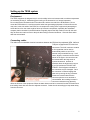
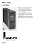
3700 NW 91st St., Suite C-200, Gainesville, FL 32606
[email protected]
phone: 352 317-7623
or
[email protected]
phone: 352 427-8535
TESS
Thermo-Electric Stimulation System
User’s Manual
Hardware T-1212-01 and 02
Software TESS V 3.0
Jan 22, 2014
1
System components
STM Stimulator head containing Peltier device
VAS Visual analog scale
THR Threshold button and event light
ECM Electronic control module
Containing
CCM current control module
CM-1 computer module
Data acquisition boards: NI PCI-6509, (dev 1), NI PCI-6221 (37 pin), (dev2)
NI PCI-8433/2 RS-485 Serial board (Port 1, COM3, 2-wire auto)
Watlow controller model PM6C2FA-1RFADAA
Hoses: McMaster# 5393K41, ¼” ID, 7/16”OD, vacuum rated (www.mcmaster.com)
Hose clamps: McMaster# 50761K31
Water circulator (not included). Min specs: 200W refrigeration to 5 degC, 10 l / min, 5psi
2
Safety
Electrical Safety
The TESS system has no FDA approval, its components are not hospital rated, and therefore TESS is
NOT a medical device. It is a custom-built system that has not been submitted to testing agencies such
as Underwriter Laboratories (UL), etc. It is intended solely for research conducted by qualified and trained
personnel intimately familiar with the contents of this manual. This equipment is NOT designed for MRI
environments. This equipment must never be operated near flammable or explosive gases or fumes.
The investigator and IRB must decide whether it is safe and appropriate for the intended experiments.
Neuroanalytics provides information that may help to make this decision:
(1) The system uses a safety ground. It must never be connected to an AC outlet in a manner that
the safety ground wire does not securely connect to the safety ground of the electrical grid.
(2) The power cable of the TESS ECM module is equipped with a GFCI plug. This plug must never
be replaced by a plug that does not have the GFCI feature. The water circulator that is needed
for thermode cooling must be connected to the outlet on the back of the ECM module and NOT
directly to a wall outlet. By connecting to the CIRCULATOR outlet of the ECM, the water
circulator will be GFCI protected and automatically be disconnected from power when the ECM is
powered OFF.
(3) The highest voltage used in the STM stimulator head is 24V DC (for the solenoid-powered
thermode motion system). The max. voltage inside the thermode (STH) itself (the part touched
by the subject) is 20V DC. The Peltier device that is powered by the 20V supply is electrically
insulated from the thermode surface.
(4) The maximum voltage used inside the VAS is 24V DC (for the VAS return solenoid). Neither the
STM, VAS or THR modules are carrying the AC voltage of the power grid.
(5) It is dangerous to use the system after any of its components has been dropped, damaged, or
exposed to fluids.
(6) Overall, the risk of electrical injury by touching the TESS system is comparable to the risk one is
exposed to when touching a household appliance.
(7) Experiments involving immersion of body parts into water carry much higher risks because the
water can be a low-impedance conduit for dangerous voltages into the body. The investigator
and IRB must carefully evaluate the risk level of such experiments and consider the use of
isolation transformers or other measures.
(8) The TESS system must never be used when the subject has an indwelling catheter. Even low
voltages could potentially be lethal when they enter through a catheter.
(9) Even though GFCI protection reduces the risk of electrical injury, this safety feature may not be
sufficient to protect certain medically compromised individuals from harm.
Thermal Safety
The risk of thermal injury is related to the temperature of the thermode and the time the thermode
contacts the skin. Even relatively low heat can result in an injury when the contact duration is long. The
investigator and IRB must carefully evaluate the intended temperature / duration combinations and
consult the relevant literature before deciding whether to go ahead with an experiment. The risk of
thermal injury is not eliminated by the fact that the subject is free to withdraw from the thermode: subjects
with reduced pain sensitivity may sustain injury without even feeling pain! Reduced pain sensitivity has
been reported to exist in individuals with certain genetic traits, diseases, or when under the influence of
certain drugs. The experimental design must always include temperature- and exposure time limits that
will lead to termination of the stimulus even when the subject reports no pain. Furthermore, the
investigator must carefully monitor the subject during experiments and regularly inspect the stimulation
3
sites for signs of inflammation or skin damage. The effects of multiple stimuli in a session are cumulative.
Even though the skin may not have suffered damage after the first stimulus, damage may occur when the
stimulus is repeated again later. The risk of thermal skin damage differs from one body location to
another and from one subject to another. The investigator must evaluate the specific risk carefully and
consult the relevant literature before deciding whether to go ahead with the intended experiment.
Pinching hazard
Do not stick fingers into the thermode opening of the STM module. Pinching and injury could occur when
the thermode moves and traps the finger. The solenoids that move the thermode are very powerful.
Children must be kept under close supervision when near the TESS equipment.
Trips and falls
The components of the TESS system are
connected with cables and hoses. Great
care must be taken that these cables and
hoses do not pose a trip and fall hazard for
the subjects and investigators. Route the
cabling accordingly and guide the subjects
around these obstacles to prevent injury due
to falls.
Route hoses and cables through the bracket
on the floor plate of the STM module to keep
them close to the ground.
Air disturbance related hazards
The forced air cooling system of the ECM module disturbs the room air and may stir up pollutants. This
equipment must therefore not be used in clean air environments.
Allergy risks
Subjects should have no known allergies or sensitivities to the materials they will come in contact with
when undergoing a TESS experiment: the thermode is made of nickel-plated copper , the plastic surfaces
of the STM and VAS modules are made of the acetal polymer Delrin (polyoxymethylene, DuPont) and the
red VAS knob of anodized aluminum.
Noise
The forced air cooling system of the ECM and the solenoid mechanisms in the VAS and STM modules
generate noise. Never attempt to muffle the sound by covering up vent holes: the electronics may
overheat and malfunction. The chilled water circulator that is needed for cooling the thermode tends to
be noisy as well. Its cooling vents must to be kept clear for optimal performance and long service life.
The use of hearing protection devices may be problematic and detrimental to the safety of the experiment
when it interferes with investigator-subject communication.
Tampering
Warning: DO NOT OPEN or TAMPER WITH the equipment! Harzardous voltages inside the
equipment cabinet pose an immediate danger, and tampering could make the equipment unsafe.
4
Setting up the TESS system
Environment
The TESS equipment is designed only for a low humidity indoor environment and an ambient temperature
not exceeding 28 deg C. Maintaining good cooling of the electronics is of utmost importance.
Do not obstruct the ventilation holes in the side walls- and the rear wall of the ECM cabinet. Do not
mount the ECM cabinet in a rack that contains other heat generating equipment or limits air flow to the
vent holes in the side walls of the ECM. Do not compromise cooling of the equipment by attempting to
muffle the fan noise: the result could be failure of electronic components, especially the embedded
computer that is contained in the ECM cabinet. Regularly inspect the filter medium in the left side wall:
dirty air filters can restrict air flow to the point that cooling becomes insufficient. Clean the filters when
dust has accumulated.
Connecting cables
The cables used to establish electrical connections between the ECM and its peripherals (STM, VAS and
THR) are equipped with UTG twist lock
connectors. The AUX connector contains
a 12V signal that can be used to
automatically switch on and off an
external relay-controlled fan tray. In all
cases, align the connector and socket as
shown in the figure: the connector can
be inserted when the large notch is
oriented downward. Insertion is
effortless when the alignment is correct.
If you feel resistance: DO NOT USE
FORCE! Check alignment instead, or
the connector may be damaged. Once
the connector is inserted engage the
twist lock by turning the ring clockwise.
Great care must be taken that the
connector pins are never touched or
contaminated: the resulting increase in
connector resistance may adversely
affect the function of the equipment. When the water hoses need to be removed from the STM make sure
that leaking water does not enter the adjacent connector. Orient the unit accordingly to keep water away
from the connector.
5
Connecting the water circulator to AC power
The circulator must be connected to the
(“CIRCULATOR”) outlet on the rear panel of the
ECM and NOT to a wall outlet. The reasons are:
(1) To extend GFCI protection to the
circulator. Remember: a serious defect of the
circulator could allow dangerous AC voltage to
reach the rest of the system through the water
hoses. GFCI protection reduces the risks.
(2) To allow the ECM to sense whether the
circulator is ON. The system will not power up the
thermode as long as no active circulator is
sensed. The thermode could be damaged if
operated without proper water cooling.
Connecting hoses
The hoses must be vacuum rated and have ¼” inner diameter. The recommended hose type is
McMaster#5393K41 (www.mcmaster.com). The hose clamps must be of a design that does not cut the
hoses and result in leaks. The recommended type hose clamp is McMaster # 5076K31.
Height adjustment
The floor stands of the STM and VAS are of telescoping design. The stand is held at the proper level of
extension by two screws. Make sure that the screws are positioned so they pass through both
components of the telescope.
Adjusting angle of STM
Loosen brake by turning red wheel counter-clockwise. Tilt head
into desired position. Moderately re-tighten wheel.
6
Contact force adjustment
The thermode is moved up into a window of the cover plate of the STM during the stimulus. The force of
the contact depends on how much the
thermode is allowed to protrude from
the window. By moving the cover plate
up and down the amount of thermode
protrusion can be adjusted. The
TESS V3.0 software includes a
manual mode. It allows holding the
thermode up while the height
adjustment is done.
Do not press hard against the
extending thermode or stimulus timing
may become inaccurate or the
program may stall.
Powering up
Plug the yellow GFCI plug into a grounded electrical
outlet that can deliver at least 15A (120V). Then
press the RESET button on the plug. The red light
will come on, indicating that AC power is ON.
After a power outage the plug will not turn ON again
by itself. The RESET button will have to be pressed
again.
On the ECM press the green START button.
The green button will light up and the computer
module inside the ECM will begin to boot. The
yellow HD indicator will light up when the
computer’s hard drive is active.
7
Once the computer’s operating system has fully booted the TESS V3.0 application will automatically
launch. No action from the
investigator is needed to start
the program.
The screen shown will appear
and the program will halt until
the password “tess” has been
entered. Password entry will
turn on system power
(indicated by red light of
RESET button turning ON).
The button can be used to
reset the computer (as in any
desktop computer). In
addition, it acts as an
emergency turn-off: it not only
resets the computer but, at
the same time, turns OFF power to the entire TESS system.
REMEMBER: In an emergency situation when there is a malfunction or an imminent risk for the
subject press the red RESET button: it will immediately turn off power to the thermal system and
the solenoid that keeps the thermode in the UP position. The computer will restart but power to the
thermal system and solenoid will not come back on unless the password has been entered.
An amber “H” (Heat) and blue “C” (Cool) LED are located next to the Watlow controller. Illumination of
these lights is indicative of the thermal system being active.
The ECM features two yellow softkeys These keys are
active only when they are lit. Their function changes
throughout the test process and is shown on the screen
in the fields directly above the respective key. Take
action as prompted and then press the appropriate
softkey to continue.
The system performs a self-test during start-up, and
prompts for user action:
(a) The water circulator may have to be turned ON
(depending on whether it has a conventional power switch or a button which needs to be pressed again
every time after power had been disconnected. On circulators with a conventional switch the switch
should be left ON all the time: the software will turn ON and OFF the circulator automatically.
(b) Engage the two orange and the central red button (VAS RETURN, PROMPT and AUTO-STOP).
When these three buttons are not IN, the self- test may fail and the computer will have to be restarted.
Once the user has checked the status of the buttons, a softkey will have to pressed to proceed.
(c) Move the VAS slider to the right endpoint when prompted. In some experimental situations this
position means “intolerable pain”. When the subject moves the slider to this extreme position the
thermode will automatically retract and the test will be interrupted (i.e., the “intolerable pain” stimulus will
be terminated). During the self-test the user will be prompted to check whether the thermode indeed fully
retracts during AUTO-STOP. The AUTO-STOP function is a safety feature which must function as
intended.
8
Water circulator temperature
Set the thermostat of the circulator to 15 deg C. For the thermal system to function properly the thermode
heatsink temperature must
be near 15 deg C. The
program halts until the
temperature of the circulating
water has cooled sufficiently.
The time this takes depends
on the starting temperature of
the water, the performance of
the refrigerator of the water
circulator and the integrity of
the circulation (no kinks in
hoses, no leaks, no bubbles).
The initialization of the
system will hold indefinitely if
the thermode heatsink
remains too warm.
Heating / cooling test
Once the circulator water has cooled to the required temperature the program continues with a test of
heating and cooling performance. The test results will appear on the screen as soon as each of the tests
is complete.
The rise time depends on
the orientation of the
stimulator head: it is approx.
0.20 sec when the thermode
has to move straight up and
less when the thermode has
to move laterally or
downward.
A rise time > 0.5 sec will
generate an error that will
lead to system shut down. In
this case, investigate
whether the thermode is
blocked by a foreign object.
The heating and cooling
rates depend on the temperature of the cooling water circulation. The recommended cooling water
temperature is 15 deg C. Please note that heating tends to be faster than cooling (this is normal for
Peltier devices). Knowledge of the heating and cooling rates may help the investigator to choose realistic
test parameters. During the transition to a new setpoint the temperature will typically first over- and
undershoot the setpoint (damped oscillation) before stabilizing. The settling time is in addition to the
ramping time and must be taken into account when planning a test protocol.
9
Rise t, heating- and cooling rates will be saved automatically in the data spreadsheet file. If experimental
data appear questionable one of the possibilities to keep in mind is sub-standard system performance
due to a technical defect. Abnormal system self-test results may be the red flag to look for.
The table shows the nominal performance values for each thermal test and the criterion for passing the
test. Failure of a thermal performance test results in an error requiring shut-down of the system. In this
case an error report file will automatically be
saved to the [TESS error] folder on the C drive.
test
nominal
criterion
Failure to pass a cooling test (especially 25 to 5
deg C) may point to insufficient heat sink
deg
deg/sec
deg/sec
timeout (sec)
cooling. Check whether the water circulator’s
refrigeration system works properly, the water
25-45
2
1
20
level is topped off, the hoses are free of kinks
and there are no leaks that lead to bubble
45-25
1.4
0.7
28.6
formation in the hoses. If no fault can be found
with the water circulation, the next item on the
25-5
0.8
0.4
50
suspects list is contamination in one of the
connectors of the ECM-STM cable.
5-25
2
1
20
Unfortunately, cleaning dirty connector pins is
rarely successful and scratching them may make matters even worse. An increase in connector
resistance of only a fraction of an Ohm may severely compromise the performance of the thermal system.
Keeping the connectors free from contamination or moisture cannot be overemphasized. Lastly,
deteriorating ramping performance could be indicative of imminent failure of the Peltier device.
Successful completion of system initialization
This screen will appear once the initialization and self-test of the system has been successfully
completed. It is now time to
set the desired experimental
parameters. This can be
done by proceeding to the
manual setting mode or by
loading a settings file from
either the [TESS set] folder
on the C drive or the [TESS
set] folder on the USB thumb
drive (D drive). However,
before the system can be
used to collect experimental
data, it is necessary to verify
that all necessary folders
exist and are located on the
proper drives.
10
Installing the USB thumb drive
USB thumb drive (must be D drive)
The TESS system will save to and read from files that must be located in specific locations on the C drive
and a USB thumb drive. The thumb drive must be of a slim design to
fit into the recessed DATA USB port. Do not connect two thumb
drives as this can lead to a reassignment of drive letters and result
in an error when the appropriate folders are not found on the D
drive. Go to the Start menu / My computer and verify that the thumb
drive appears as the D drive. If it shows up with a different drive
letter follow the instructions below to make the thumb drive the D
drive.
Reassigning drive letter
If the thumb drive is not plugged into the
“DATA” USB port or is assigned a drive letter
other than [D] the TESS program will be
unable to save data and an error message
may appear.
To change the drive letter open the control panel.
Go to” Administrative Tools”.
11
Click on “Computer
Management”.
In this example the thumb drive appears as
the E drive, and this will not work and requires
changing.
Right click the drive, choose
“Change Drive Letter and
Paths…” and make the change.
The thumb drive must be the D
drive.
12
Time format
The time format of the computer must be set for 24 h (military time). This format is necessary for TESS to
generate data filenames. The familiar AM/ PM time format will not work.
Files and Folders
Verify that all the needed folders exist on the C drive and on the thumb drive (D drive). The table lists all
the folders that must be present on the root level of the C drive and D drive. The folder names must be
exactly as shown.
Settings files
The first time an experiment is set up the task of setting each individual control on the front panel is
unavoidable. However, these settings can then be saved to a settings file (either on the C drive or the
USB thumb drive (D drive). The settings can be loaded from this file the next time the same type of
experiment is performed. Settings files generated with an earlier version of the software are not fully
compatible with TESS V3.0.
Data files
TESS features 7 modes of operation (0-6) each allowing a different type of experimental protocol. The
data files will be saved to folders that are
specific to the mode of operation that has
been used. The program first saves to the
appropriate folder on the C drive (backup)
and then to the folder on the thumb drive.
Segregation of data files into mode-specific
folders assures that all the spreadsheet files
in a given folder have a uniform format. This
makes it easier to use macros for automated
data analysis. The data filenames contain a
letter code that identifies the mode of
operation that was used (“M” for manual
mode, “CE” for Contact timing mode, etc.).
TESS generates filenames for data files automatically using the settings for Subj #, Exp #, Test #, the
code for the mode of operation, date and time. This assures that there are no duplicate filenames.
Furthermore, it makes the saving process faster because the investigator does not need to enter a file
name, and data can be located without opening files.
13
Error files
An error report file is generated automatically when an error requiring system shutdown occurs. The file is
saved into the [TESS error] folder on the C drive. The file is in spreadsheet format and contains the rise
time of the last thermode solenoid activation, the results of the thermal test during system initialization, an
indication whether the water circulator was detected, a code identifying the type of error and information
regarding where in the program the error occurred. The error file should be e-mailed to Neuroanalytics
when the problem requires tech support.
Powering down
To shut down the system go to a screen that offers the “Quit test session” option. Press the QUIT softkey
and wait until the red RESET button is no longer illuminated and the water circulator has turned off. Now
go to the START menu and select the shutdown option. Once the computer has shut down the screen will
go dark, all fans and panel lights will turn OFF.
Do not install additional software
Setting up a computer-based data acquisition system can be quite challenging. Data acquisition cards
and driver software must be installed, configured and tested for compatibility. TESS has its own built-in
Windows computer so the user does not have to deal with these issues. The installation of any additional
software is strongly discouraged! Printer drivers, spreadsheet programs, anti-virus software, games, etc.
can lead to incompatibilities resulting in malfunction or inaccurate stimulus timing. The TESS ECM
module intentionally has no internet connectivity to reduce the possibility of a malware infection. The fact
that TESS has no connection to the institutional intranet should mitigate potential concerns of IT
departments regarding the lack of anti-virus software. In any event, virus software would be of little
benefit on the TESS system because it would be difficult to keep it updated without internet connection.
TESS saves its data to a USB thumb drive (which must be inserted into the DATA USB port). Before this
thumb drive is connected to TESS it should be checked for viruses on a computer that is equipped with
anti-virus software.
Upper front panel controls and indicators
The upper front panel is virtual, i.e., on the computer screen. It contains controls and indicators. Controls
have black text on a white-, colored- or grey background. A grey background indicates that the control is
disabled, i.e., its value can’t be changed. The range of many controls is limited and may depend on how
other controls are set. If an attempt is made to enter an out-of-range value the setting will automatically
change to the nearest allowable value. Once an experiment is underway controls are disabled and can no
longer be changed. Certain protocols can modify the settings of controls. In this case the numbers shown
on the control turn from black to red.
Indicators have a black background. They are updated by the program. The displayed number
represents the value at the time the last sample was taken. This may not necessarily be the real-time
value.
Some controls may morph into indicators and change their appearance accordingly during certain
protocols.
The first control to be used is the “Mode” control. It is visible and active when the Parameter setting
screen is on display. There are 7 Modes of operation that can be selected: “Manual mode”, “REDSTIM
continuous”, “REDSTIM tapping”, “Contact timing”, “Ramp timing”, “Arbitrary wave” and “Linear slope to
threshold”.
14
Lower front panel controls and indicators
1. START button press to start system
2. HD light
light indicates that computer module is ON
light indicates computer C drive activity
3. RESET
press to reset computer
and turn OFF power
light indicates that system power is ON
(without system power: no heating/cooling or
thermode contact)
4. Softkey 1
press to respond according
to prompt
light indicates that key is active
5. Softkey 2
press to respond according
to prompt
light indicates that key is active
6.
7.
8.
9.
10.
11.
VAS RETURN IN: VAS RETURN enabled
PROMPT
AUTO-STOP
H , C LEDs
FAULT panel
DATA ACQ
CONTACT
light: VAS return solenoid is energized
(VAS return feature is exclusive to “Contact
timing” and “REDSTIM tapping” modes)
IN: audible prompt enabled
light: visible prompt (unaffected by switch)
IN: AUTO-STOP enabled
light indicates that AUTO-STOP has occurred
light indicates whether thermal system is in heating (H) or cooling (C) mode
see Fault management section
light indicates that data are being collected
light indicates that thermode motion solenoid is energized
15
12. THR
light is used in “Linear slope to threshold” mode, indicating threshold reached
13. WATLOW
14.
15.
16.
17.
temperature controller shows thermode temperature in red and setpoint in green
digits. Do not press buttons! If you accidentally did the situation may be saved
by pressing Infinity button or by pressing the red RESET button (3).
VAS display
shows position of VAS slider as % of full travel
AUX USB port normally not used
DATA
USB port for connecting thumb drive to which data will be saved
KEYBOARD
USB port for connecting keyboard / tracking device
Fault management
TESS is able to automatically respond to a number of fault
conditions by turning OFF system power and prompting to
shut down computer. The fault indicator panel provides
information regarding the nature of the fault condition. This
panel consists of 4 red LEDs (WATER CIRC, HEATSINK,
TEMP SENS, CURR CTRL).
WATER CIRC LED is lit
Possible causes:
water circulator not ON or not connected. Remedy: turn ON water circulator.
HEATSINK LED is lit
Heatsink of thermode overheating (>55 deg C)
Possible causes:
Water circulator not working properly
Water level in circulator too low
Circulator temperature too high (should be near 15 deg C)
Cooling hoses kinked, damaged or leaking
Temperature sensing problem (in this case the “TEMP SENS” LED may also be lit)
TEMP SENS LED is lit
Connection to temperature sensors in thermode interrupted (connector loose, wires broken) :
Check whether cable between ECM and STM is properly connected.
Electrical noise interfered with temperature signal
Short circuit in temperature sensing circuit (e.g., due to moisture condensation inside thermode)
CURR CTRL LED is lit
Air cooling of ECM cabinet insufficient: check whether air vents and filters are clear and room temperature
is below 28 deg C near the air vents of the ECM (in the sidewalls and rear).
A short or lower than normal resistance in the Peltier circuit: check whether water is leaking out of STM
module (internal hose may be leaking and water may have shorted out electrical connections); check
condition of cabling between ECM and STM.
Overcurrent condition (could be indicative of a component failure inside the ECM).
16
FAULTS will lead to saving of an error report file into the [TESS error] folder on C drive and automatic
shutdown of the equipment. When this happens restart the computer and see whether the fault reoccurs.
An isolated FAULT event need not be of major concern. However, repeated FAULTs are indicative of a
potentially serious problem that needs attention before experiments can continue. Make a note of which
LEDs on the FAULT panel were lit prior to automatic shut down. The information will help technical
support to diagnose the cause of the problem.
The fault management system can detect shorts in the Peltier circuit and turn on the “CURR CTRL” LED
on the front panel. However, a failure that leads to an open circuit can be detected only indirectly when
the heating and cooling ramps become too shallow to pass the thermal self test during system
initialization.
Idling
When the system is idling for a prolonged period of time, i.e., while waiting for the next subject to show
up, use a moderate temperature setpoint (e.g., 25 deg C) to reduce the thermal stress on the system.
Modes of operation
Manual Mode (M)
The Manual mode has only two
controls: a control for setting the
duration of the test (range 5- 600
sec) and a control for the
temperature setpoint (range 0-55
deg C). When the test is running
the temperature and VAS are
sampled continuously at a rate of
1 S/sec. An indicator shows how
many samples (or seconds) have
elapsed. A progress bar shows
the elapsed time as a percentage
of the set Test duration.
Once the test has been started
pressing the left softkey will
activate the thermode solenoid and move the thermode UP, i.e., into the window. The “Stim elps”
indicator will display the number of seconds the thermode has been in the UP position. The left softkey
will now be assigned to move the thermode back down (into the recessed position). Only one stimulus
pulse is possible during the test duration. The test can be aborted at any time by pressing the right
softkey (STOP). Once the test has ended the option to save or clear the data will appear. The AUTOSTOP function is active when the corresponding button on the front panel is pressed but AUTO-STOP
events are not documented in the data spreadsheet. The manual mode is useful primarily for making
17
contact force adjustments, i.e., to keep the thermode in the up position for measuring how much the
thermode protrudes from the window.
REDSTIM continuous Mode (RC)
Response-dependent Stimulation (REDSTIM) establishes feedback control between the stimulator and
the subject. It is used to reach
and maintain a preset average
pain intensity level. The
stimulator makes automatic
adjustments to the temperature to
keep the pain level near the
desired setpoint. The thermode
temperature required to elicit the
set pain intensity serves as
response variable and indicator of
pain sensitivity. REDSTIM mode
is useful when subject
populations with a wide range of
thermal pain sensitivities need to
be compared. It is well known
that the sensitivities of a healthy
individual and a patient with a condition like fibromyalgia may differ so much that common test
parameters for both may be difficult to find. A temperature that is barely painful for a healthy individual
may be intolerably painful for certain patients. It may take a pilot experiment simply to establish what
parameters should be used. The REDSTIM method avoids this problem altogether. An easily tolerable
pain intensity setpoint is chosen by the investigator. In addition, a temperature limit (“T limit”) is set to
avoid thermal injuries in subjects that are abnormally insensitive to thermal stimuli. The REDSTIM test
can be conducted in the HOT or in the COLD range. In the HOT range the system assumes that higher
temperatures are more painful. When the VAS rating exceeds the setpoint the stimulator will
automatically lower the temperature. In the COLD range the stimulator operates in the opposite direction,
i.e., when the VAS setpoint is exceeded the stimulator will increase the temperature. In “REDSTIM
continuous” mode the thermode remains in contact with the skin continuously throughout the entire test.
“T start” and “T limit”
In HOT mode the starting temperature (“T start”) has a range from 25-55 deg C and the temperature limit
“T limit” must be > / = “T start” and < /= 55 deg C.
In COLD mode “T start” has a range from 0-38 deg C. “T limit” must be < / = “T start” and > / = 0 deg C.
The controls will not allow settings that violate these range limitations. It is important that the starting
temperature is never painful. In COLD mode the starting temperature must never cause heat pain. The
control algorithm assumes that the change in pain intensity is linearly related to the temperature. When
pain increases in one direction (e.g., higher temperature), it must always decrease in the other direction.
The REDSTIM algorithm has the authority to adjust the thermode temperature between “Tstart” and “T
limit”. It will not set temperatures outside this range regardless of the VAS ratings.
18
“Smpl interv”
Temperature and VAS are sampled continuously throughout “REDSTIM continuous” experiments. The
sampling interval can be set to 1 sec, 1.5 sec or 2 sec.
Induction phase
The test can be conducted with a monophasic, biphasic or no induction phase. During the induction
phase the temperature increases (HOT mode) or decreases (COLD mode) gradually (linear slope). In
biphasic mode the “Rate ph 1” setting applies until the VAS rating has increased to 65% of the VAS
setpoint. The “Rate ph 2” setting applies thereafter until the pain intensity rating has reached 90% of the
setpoint. At that time the transition to the first Maintenance phase takes place.
In monophasic mode the “Rate ph 1” setting applies until 90% of the pain intensity setpoint has been
reached at which point the transition to the Maintenance phase is made.
“Rate ph 1”
Rate of temperature change in deg /sec. Range: 0.1 - 1.0 deg / sec
“Rate ph 2”
Rate of temperature change in deg / sec. Range: 0.1 – 1.0 deg but < /= “Rate ph 1”.
“Rate ph 2” cannot be > “Rate ph 1”.
Maintenance phase 1
A control allows to select either REDSTIM or CONSTANT mode. In CONSTANT mode the temperature
setpoint at the end of the Induction phase (i.e., when VAS first reached 90% of the setpoint) will be
maintained.
Maintenance phase 2
A control allows to select either REDSTIM mode, CONSTANT mode or NONE (no phase 2).
Both maintenance phases feature the following additional controls:
VAS set
It is the pain intensity setpoint (0-100%). Setpoints >40% should be avoided or AUTO STOP events may
become too frequent, especially in inattentive subjects that tend to have widely oscillating VAS ratings.
n smpl
This control determines the duration of the Maintenance phase (range 0-600 samples). Note that the
duration in seconds depends on the chosen sampling interval. At a “Smpl interv” setting of 1.0 sec the
duration in seconds will be the same as the number of samples chosen. If the “ Smpl interv” setting is 2.0
sec and the “n smpl” setting is 20 the resulting duration of the Maintenance phase would be 40 sec.
Gain
Each Maintenance phase features 3 “Gain” controls. Gain is defined as the temperature adjustment (in
deg C) that is made for a 10% deviation from setpoint during each sampling period. Let’s assume that in
HOT mode the Gain is set to 0.4, and the pain intensity setpoint to 35%. If the actual VAS position is
19
sampled as 30% (5% below setpoint) the temperature will be adjusted upward by 0.2 deg C for the next
sampling period.
The system allows using different Gain settings depending on whether the VAS rating remains steady,
trends in toward the setpoint or away from it. The maximum possible temperature adjustment / sampling
period is 0.8 deg C regardless how much the VAS rating deviates from the setpoint.
“Gain tr out”
This gain applies when across three subsequent samples the pain intensity rating progressively moved
away from the setpoint. The range for this control is 0.1 – 1.0.
“Gain steady”
This gain applies when there is no unidirectional change in the VAS rating across 3 consecutive samples.
The range criteria are 0.1 – 1.0 and < /= “Gain tr out”.
“Gain tr in”
This setting applies when the sampled VAS rating unidirectionally moves toward the setpoint across 3
consecutive samples. This gain should be smaller than “Gain steady”: considering that the VAS rating is
already trending toward the setpoint, a small temperature adjustment should suffice.
Temperature control will be proportional only (and not trend dependent) when all three gain settings are
the same. Note that with all “Gain” settings = 0 no VAS-dependent temperature adjustments will be
made, and the system behaves as in CONSTANT mode.
deadbd
The deadband is a band above and below the VAS setpoint within which REDSTIM does not make any
temperature adjustments. Example: HOT range, VAS setpoint = 30; Gain = 0.4, deadbd = 2: no
adjustment if VAS is between 28 and 32. Adjustment is -0.4 deg if VAS is 42 (assuming no trend effect).
A small deadband setting may help to reduce the contribution of trend-induced pain modulation such as
offset analgesia without significantly compromising the control authority of the REDSTIM algorithm.
A large deadband setting may be useful for studies of sensitization and adaptation phenomena during
prolonged constant temperatures while preventing an escalation of the pain intensity to intolerable levels.
A constant temperature is maintained as long as the VAS rating does not exceed the bounds of the
deadband.
Assessing the subject’s pain rating performance
In an experiment with two REDSTIM maintenance phases with identical parameter settings but different
VAS setpoints one would expect that the average temperatures would change from one phase to the
next. In HOT mode the transition to a phase with a higher VAS setpoint should lead to a higher average
temperature. If there is no logical relationship between VAS setpoint and average temperature one would
have to question the subject’s rating ability and therefore the validity of the data.
20
The data file generated after each REDSTIM test contains Running Averages for each Maintenance
phase. For the first 10 samples of the phase all the samples collected thus far are averaged. Thereafter,
the Running Average of the last 10 samples is calculated (RA10). The Running Average acts as a
smoothing
function that
makes it easier
to see trends of
sensitization or
adaptation
across the
duration of the
Maintenance
phase. The
section
“AVERAGES”
contains the
mean values
across all
samples of the
Maintenance
phase. The
temperature
average is a
measure of pain
sensitivity. The
VAS average
may serve as
an indicator of
the subject’s
pain rating
ability. It should
be within +/-4
units of the VAS
setpoint or the
subject’s rating
performance
(and therefore
the validity of
the data) must
be questioned.
The last column
of the
spreadsheet
(“Term”)
contains a note if the test was aborted because the investigator pressed the STOP key or the pain rating
reached 100% and triggered an AUTO-STOP event.
21
REDSTIM tapping Mode (RT)
In “REDSTIM tapping” mode
the thermode is brought in
and out of skin contact
periodically (“tapping”). The
algorithm for the temperature
adjustments in tapping mode
is the same as in “REDSTIM
continuous” mode, and the
two modes share a number
of controls. The shared
controls have the same
ranges in both modes. During
the induction phase of
“REDSTIM tapping”
temperature adjustments are
made once during each
period, i.e., immediately after VAS sampling.
The “REDSTIM tapping” panel features controls for setting the tapping parameters.
Period
The range of the “Period” control for Induction and
Maintenance phases is 2-300 sec
Cont
Min: The shortest possible contact duration setting
for all phases is (rise t + 0.5 sec).
Max:
IF
Period > / = 12 sec Longest “Cont” setting
is (Period - rise t - 2.5sec)
ELSE Longest “Cont” setting = (Period - rise t – 0.8
sec)
n Prd M1
For Maintenance phase 1 the range for the number of Periods is 1-300.
n Prd M2
For Maintenance phase 2 the range for the number of periods is 0-300.
When “n Prd M2” is set to 0 the controls for Maint phase 2 will be hidden, and no second Maintenance
phase will take place.
Temperature and VAS are sampled once during each period: the temperature at mid-contact, VAS
halfway into the inter-stimulus interval.
22
The data file
for “REDSTIM
tapping” has
the same
features as the
spreadsheet
for the
“REDSTIM
continuous”
mode with the
addition of
columns for
Period and
Contact
duration.
VAS return
Certain
settings of
“Period” and
“Cont” enable
the automatic
VAS return
feature: at the
end of each
period, after
the VAS has
been sampled,
a solenoid is
energized to
return the VAS slider to the left endpoint. The feature is only active when the following conditions are met:
Period >/= 12 sec AND Cont > / = 2 sec. Automatic VAS return can be disabled by the investigator by
releasing the VAS RETURN button on the lower front panel.
Possible use for “REDSTIM tapping” protocol
The “REDSTIM tapping” mode may be useful for conducting “windup” experiments where subjects with
vastly different pain sensitivities need to be compared and the temperature rather than the VAS rating
serves as response variable. The method automatically finds an appropriate stimulus temperature range
for each subject, and comparisons are made at the same pain intensity level.
The risk that pain intensities escalate to intolerable levels in highly sensitive subjects is much smaller
when the REDSTIM method is used. Pilot experiments to find an appropriate stimulus temperature for
each subjects are unnecessary.
The “REDSTIM tapping” mode can also be used for conventional windup experiments where the VAS
rating is the response variable. A large deadband is set as a safeguard against an escalation into
unacceptably high pain intensities. Within the bounds of the deadband the protocol work exactly as the
conventional “windup test”.
23
Contact timing Mode (CE)
It may be true that the tactile component of a tapping stimulus may be a confounding factor in thermal
pain sensitivity studies. However, it is important to realize that protocols that keep the thermode in skin
contact continuously and time the stimulus by ramping up and down the temperature are not without
problems either. No matter how sophisticated the technology, a rapid thermode temperature change
always leads to transient over- or undershoots of the new setpoint or damped oscillations. The subject’s
sensory system may respond to these transients by a temporary increase or decrease of pain sensitivity
(e.g., “offset analgesia”). Stimulus timing by ramping up and down the temperature may be a good
experimental strategy for prolonged stimuli and infrequent temperature changes. Stimulus timing by
tapping, on the other
hand, brings clear
benefits in
experiments where
stimuli have to be
brief and free of
transients. The
subject is not
exposed to
temperature
transients because
the thermode
temperature is
changed during the
inter-stimulus
interval while there is
no contact with the
skin. The longer the
inter-stimulus interval the more precise and stable the temperature at the time of thermode contact.
The contact timing mode is a good method for conducting “windup” experiments where series of brief
stimuli are administered to study sensitization by temporal integration. The method is equally useful for
acquiring stimulus intensity response curves: the temperature is incrementally changed from one stimulus
contact to the next and the VAS response is recorded following each. This protocol works best when the
stimuli are neither too brief (hard to rate) nor too long (risk of sensitization): contact durations of 3 sec
have been used successfully. The intervals between stimuli should be long enough to minimize
sensitization that carries over to the next stimulus: intervals of 15 sec (Period setting of 18 sec) have
been recommended by some investigators.
The system can be programmed to deliver an ascending series of stimuli with incremental temperature
increase followed by a descending series (or vice versa). Different criteria can be used for series
termination: (a) number of stimulus contacts (n crit), (b) temperature (T crit), (c) exceeding a set VAS level
(asc to “VAS crit”), or (d) dropping below a set VAS level (desc to “VAS crit”). Please note that multiple
criteria are in effect simultaneously: the first criterion that is met will terminate the series.
24
Once the solenoid has been activated the thermode will rise until it reaches skin contact. The rise t of the
most recent contact is displayed in
the top row of the front panel screen.
It is typically around 0.2 sec when the
thermode head is pointing upward.
Period and contact don’t begin until
the thermode has reached the UP
position. The period continues until
the end of the rise t that precedes the
next contact.
Temperature sampling.
The process temperature is sampled
once during each contact period. The
“T smpl” control sets the precise time
point of temperature sampling. In
most cases it is best to sample near
the middle of the contact duration.
VAS sampling.
The VAS rating is also sampled once
during each period, always while the thermode is retracted. The timepoint of the VAS sample is set in the
“VAS smpl” control. Sampling should not occur too soon after the contact ends, or the subject will not
have enough time to rate the pain intensity. In experiments with long inter-stimulus intervals it should not
be more than about 5 sec after the end of the contact or the rating may represent pain memory rather
than actual sensory intensity. In any event, it is important to standardize temperature and VAS sampling
times for all tests in a study or the results may not be comparable. The event light indicates to the subject
when the window for rating the pain is open.
The applicable ranges for each
control can be gleaned from the
table. Please note that the
ranges for “C dur” and “VAS
smpl” depend on whether the
VAS return feature is active or
not. The program will
automatically generate a VAS
return signal when the Period is
at least 12 sec and the contact
dur 2 sec or longer. Even when
these criteria are met the
investigator has the option to
disable the VAS return by
releasing the “VAS return”
button on the lower front panel.
However, this button will have
no effect on the allowable range
of the “C dur” and “VAS smpl”
controls.
25
Ramp timing Mode (RE)
In this protocol the thermode remains in contact with the subject for the entire duration of the test. Data
are sampled
continuously
throughout the test
at a rate of 1S/sec.
The stimulus is
timed by ramping up
and down the
temperature of the
thermode. The
protocol is divided
into episodes (set “n
Episd”). Protocols
can have up to 12
episodes.
A front panel control
(F/SL) allows to
choose the
characteristics of the
temperature transition from one episode to
the next: it can be “as fast as possible”
(FAST mode) or a controlled slope (SL
mode). In the SL mode a control for setting
the steepness of the slope appears on the
screen. Select the FAST mode for
matching a protocol conducted with earlier
versions of the TESS software. T ini is the
setpoint that applies before the test has
begun. A moderate T ini setting prevents
prolonged extreme temperatures during
long waiting periods between tests. After
the START key has been pressed the test
will not begin until the temperature set in
the T1 control has been reached. Unless
T1 is very high or very low it may be best
to set T ini to a value at or near T1 to
minimize the delay unitl the test starts. For
each episode the temperature (T1….T12)
and duration (“dur 1”…”dur 12”) can be set
individually. The episode duration always
includes the temperature transition to the
setpoint of the episode. When setting the
duration the investigator must therefore
factor in the time it takes to reach the episode’s setpoint or the desired temperature may never be
reached. This is particularly important when the slope setting (deg/s) is shallow. The “n Episd” counter
26
indicates which Episode is in progress, and the “dur” counter shows the elapsed time (in sec) within the
episode.
Pressing the STOP softkey terminates the test while pressing the SKIP softkey skips to the next episode.
The test is also stopped by the AUTO-STOP function (pain rating 100%) unless the investigator has
disabled it by releasing the AUTO-STOP button on the lower front panel.
The control ranges are as follows:
N Episd set
1-12
T ini
0-55 deg C
T1 … 12
0-55 deg C
dur 1…12
5-600 sec
deg/s
0.1 – 1.0 deg/s
Before committing to any parameter settings it is advisable to conduct a dry run, save and chart the
temperature data in order to determine whether the desired temperature transitions are realistically
possible within the time periods available.
The ramp timing method is most useful for “ramp and hold” experiments where the temperature is ramped
up to a nociceptive level and then held there for a prolonged period of time. Please note that FAST
transitions (the only transition mode available in earlier versions of the software) have no uniform rate.
The rate decreases as the new setpoint is being approached, slight over- and undershoots are typical,
27
and the characteristics differ depending on the temperature range. The SLOPE (SL) transition mode
leads to a more predictable transition and may be preferable in cases where the response to given
temperature levels may be affected by the characteristics of the preceding transition.
This type of experiment is often used to study sensitization or adaptation phenomena associated with
prolonged stimulus exposure. The “Ramp timing” mode is not recommended for “windup” experiments
where short thermal pulses are needed because the thermal ramps are likely to be too slow and
overshoots, undershoots or oscillations may become confounding factors.
The spreadsheet documents the temperature transition mode for each episode and indicates how each
episode was terminated, i.e., whether a STOP, SKIP or AUTO-STOP event took place.
The sample count (Smpl) is reset after each episode. The sampling rate for the process temperature and
VAS is 1 S/sec and cannot be changed.
Arbitrary Wave Mode (AW)
The thermode remains
in contact throughout
the entire test and
temperature and VAS
are sampled
continuously at a rate
of 1S/sec. Up to five
temperature levels are
possible.
The temperature
transition
characteristics can be
selected: in FAST (F)
mode the transition is
“as fast as possible”; in
SLOPE (SL) mode the
rate of temperature
change (deg / s) can be set.
The system offers four choices how to terminate the temperature slope that makes the transition between
two constant temperature levels:
“Temp”; the slope is allowed to progress until the next preset temperature (e.g., “Temp 2”) is reached.
“VAS>/< set”: the slope stops when the VAS rating reaches a set level (e.g., “set 1-2”) and the
temperature of this moment will become the setpoint for the next constant temperature phase (instead of
what was set with the “Temp 2” control). The graph illustrates an example where initially “Temp 2” was set
to 50 deg C, however, Slope 1-2 was terminated early when the VAS rating had reached 40%. The
duration of the subsequent STEADY phase was set to 0. The program took 1 sample at the endpoint
temperature (sample # 50) before initiating the next temperature transition.
28
“dT” : the next temperature
setpoint is defined as a
difference from the preceding
temperature level. This mode
is useful when the final
temperature of the preceding
phase is not known at the
beginning of the test, e.g.,
because the transition phase is
terminated based upon a VAS
criterion as in the example
shown in the graph. In this
case, the numbers in the Temp
controls will turn from black to
red, indicating that they have
been modified. This is
important for the investigator to
know when the same test
needs to be repeated: either
the modified Temp settings
need to be manually returned to the original values or the settings need to be reloaded from the SET file.
“Duration”: once the controls “Temp 1”, “deg/s 1-2” and “Temp 2” have been set it is possible to
calculate the duration of the slope. The result of this calculation will be displayed on the screen (in
“Duration” mode only). Assuming a perfectly linear slope, the temperature should have reached what
was set on “Temp 2” precisely at the end of the calculated duration. In “Duration” mode this calculated
duration (not the temperature) is the criterion for ending the slope. If the slope is not linear the new
temperature will be different from what was set on the “Temp 2” control. In this mode the duration of the
temperature transition is clearly defined but the new temperature setpoint is not. In the “Temp.” mode the
new temperature setpoint is clearly define while the time it takes to reach it is not.
The table shows the ranges of the controls. Two adjacent temperature levels must never be the same. If
an attempt is made to enter the same temperature for directly adjacent phases, the computer will
automatically make a small change (0.1 deg) to one of the settings to keep them different.
29
The Arbitrary Wave mode may be useful for assessing trenddependent pain modulation. The subject can be exposed to
upward and downward trending stimulus intensities. One can
hypothesize that the pain ratings at the same temperature will be
different depending on whether the temperature was trending up
or down. The effect may be a function of the slope rate (deg /
sec).
Linear slope to threshold Mode (TH)
This mode of operation
is designed to conduct
pain threshold
experiments. The
thermode remains in
contact with the skin
throughout the test, and
the temperature
gradually rises (or -- in
the case of cold-pain
threshold experiments-drops) from “T slope ini”
toward “T slope end” at
a preset rate (“slope
deg /s). A progress bar
on the screen shows % progress of the
temperature slope toward the set end point. The investigator can
choose between two methods for the subject to respond when
threshold has been reached: pressing the “Threshold button” or
moving the VAS above a preset level. The thermal slope stops and
the thermode is retracted when the threshold response occurs. The
table shows the applicable range limitations of the controls. The “C
lead t” control sets the time delay between thermode skin contact and
begin of the thermal slope and data sampling.
30
Saving files
Test Data
At the end of a protocol the investigator is prompted to either save the data or clear them without saving
by pressing the respective softkey. Verify
that the thumbdrive (must be D drive and
contain properly named folders) is plugged
into the DATA USB port before initiating a
SAVE. The data are first backed up in the
respective folder on the C drive. Then the
same data are saved to the thumb drive (D
drive). If the thumb drive is either not
plugged in or does not have the drive letter
“D” the save process will fail. However, as
the data have already been backed up to
the C drive they will not be lost. They can
later be copied manually from the
appropriate folder on the C drive to the
thumb drive. The files are saved in the
Excel Comma Separated Values (CSV)
format which is recognized by the
Microsoft Excel application.
The data spreadsheet (“Manual” mode used as an example) contains the results of the system self-test
that occurs during the initialization phase of the program, comments the user may have written and a data
section where each row represents a sample. In many cases the spreadsheet also documents the
settings and a condensed data summary.
Settings
At the beginning of the program
the user can select whether to load
a SET file from the USB drive or C
drive or to set the parameters
manually. The latter must be
chosen if no SET file has
previously been saved. Once a
SET file has been loaded the user
is given the opportunity to modify
the settings. The user can then
PROCEED to a screen that allows
saving the modified settings to
either the C drive or the USB drive
but not to both simultaneously. If
the settings file is needed on both
drives there will be another opportunity after the test has been run and the program has returned to the
first screen.
31
The settings file contains all parameters, including those of modes of operations
that are not currently active. If a settings file is loaded for a “Contact timing”
experiment (CE) the front panel for this mode of operation will appear, and all the
controls will be set from the information contained in the file. However, the settings
of the parameters of all the other modes will also be saved. The parameters can be
saved to either the [TESS set] folder on the C drive or the [TESS set] folder on the
USB thumb drive (D).
Once the file name menu appears it is possible to navigate to other locations on
the computer where the user may keep folders with SET files.
SET files are text files (not Excel files), however, they can be opened with MS
Excel. It is recommended to generate settings files by entering the appropriate
values on the front panel and then saving a SET file. Using a text program instead
bears the risk of syntax errors with unintended consequences. The illustration
shows a brief section of a SET file.
Error report files
An error report is saved in Excel CSV format into the [TESS error]
folder on the C drive when a system fault requiring system
shutdown occurs. The filename contains information regarding date
and time of the event. The system test results include the rise time
of the last
thermode
solenoid
activation
and the
heating/
cooling rates recorded during system initialization.
The error location code (“Loc”) points toward
where in the program the error occurred.It begins
with a letter sequence which identifies the active
mode of operation.
The table lists the different error types. The error
report file should be e-mailed to Neuroanalytics
when technical support is requested.
32
Equipment cooling
ECM Cabinet
The components inside the ECM cabinet are densely packed, and keeping them cool requires strong
forced air circulation. The fans in the ECM may be noisy but they are necessary to maintain adequate
ventilation of the cabinet. If the air flow is obstructed, e.g., due to an attempt to muffle the sound, or dirt
accumulation in the air filters, electronic components may be damaged. Overheating of the current control
module (CCM) will trigger a FAULT and the “CURR CTRL” light on the front panel will light up. The
computer module has privileged access to cooling air because it is especially sensitive to thermal stress
but it does not generate a FAULT when it overheats.
Air filter cleaning
The air filters are located in the left sidewall of the ECM. They must be cleaned periodically (3-6 month
intervals recommended in
a clean laboratory
environment).
Removal of 2 stainless
steel screws (Phillips
heads) for the lower fans
and 4 screws for the large
upper fan gives access to
the filter elements which
are located behind the
perforated cover plates.
The filters may be cleaned
with a brush or they can
be replaced. The filter
medium is inexpensive
and can be purchased in
bulk from McMaster-Carr
(www.mcmaster.com).
The order number is
2195K51. New filters can
be cut to size with
scissors. Failure of any fan requires immediate repair to prevent more serious secondary damage.
Ambient temperature
The ambient temperature next to the side and rear walls of the ECM cabinet should not exceed 28 deg C.
If the equipment is mounted in a rack cabinet, it is important that the space lateral to the equipment is well
ventilated and no other heat generating equipment that could lead to heat buildup is placed in the same
rack.
33
Thermode
The thermode is heated and cooled by a Peltier device. This is a solid-state heat pump that pumps heat
between a thermal mass (heatsink with internal water circulation) and the thermode surface. Thermal
energy is pumped from the heatsink to the thermode in heating mode and vice versa in cooling mode.
Proper temperature control depends on a relatively stable heatsink temperature, i.e., it should not heat up
much when the thermode is being cooled. For best results, the heatsink temperature must be held at
approximately 15 deg C. This is accomplished by maintaining water circulation between a thermostatcontrolled refrigerated water circulator and the STM module.
Inadequate heatsink cooling could put the Peltier device at risk when the thermode is in cooling mode
because the side of the Peltier device facing the heatsink could get too hot.
The system has two built-in safeguards to assure that the heatsink does not overheat:
(a) The water circulator is powered through an outlet in the back of the ECM. The electrical current
that flows through this outlet is electronically monitored. If no current is sensed, the thermal
system will not be turned on, and the red “WATER CIRC” LED on the front panel will be lit.
(b) A temperature sensor is embedded into the heatsink. When the heatsink temperature exceeds
55 deg C, a FAULT is generated, the system is automatically turned OFF, and the red
“HEATSINK” LED on the front panel will be lit.
Deionized water is recommended as cooling medium. Note: do not use additives such as antifreeze!
They may lead to foaming in the non-pressurized cooling circuit. This will dramatically reduce cooling
performance.
TESS design and maintenance
This chapter should help the user gain a better understanding of how the TESS system works and why
certain components of the TESS system require maintenance or periodic replacement. Design- and
usage-related factors are discussed.
ECM module
The Electronic Control Module (ECM) contains a number of fans that maintain critical air flow around heat
sensitive electronic components, most importantly, the microprocessor of the embedded computer and
the power transistors of the current controller. Intake fans are equipped with filters which require regular
cleaning or replacement. Unusual changes in the fan noise may be indicative of a fan failure, a defect
that requires immediate attention to prevent heat damage to electronic components. The computer
module is the most vulnerable to heat damage. The electronic sub-modules of the ECM, when operated
with adequate cooling, are largely maintenance-free and are expected to have a service life of many
years. Many of the electronic sub-modules are of the plug-in design. This facilitates repair, should it ever
be necessary.
VAS module
Even though the VAS module contains moving parts, its service needs are minimal due to the rugged
design. A micro-switch that activates the AUTO-STOP function when the pain rating reaches the
maximum may need calibration or replacement every few years.
34
STM module
The Stimulator Module (STM) is the peripheral component that delivers the thermal stimulus to the skin of
the subject. The frequent movements of the thermode (into and out of skin contact) lead to repeated
flexing of the wires that
connect to the STH module.
Eventually, these wires will
break and require
replacement. A pair of
springs need replacement
when they are no longer
able to fully retract the
thermode. Spring failure
may not be obvious as long
as the STM is operated with
the thermode facing up.
However, when the
thermode is facing
downward, the springs have
to be strong enough to
retract the thermode against
the force of gravity.
When the solenoids’ action
have moved the thermode to
their fully extended position a
microswitch will close,
triggering a reduction of
electrical power to the
solenoids, and generating a
signal used for measuring the
time it took for the thermode to
rise (rise t). Unusually short or
long rise times and system
startup problems may be
indicative of a microswitch
defect.
The water cooling system
includes internal tubing that
will deteriorate over time.
Kinks may develop in the
tubing and restrict the water
flow (typically resulting in
system startup problems). The
tubing should be inspected
annually and replaced when
necessary because internal leaks could potentially damage nearby electronic components. Over time,
the water cooling system may become ineffective when it becomes restricted by mineral deposits, and
35
this may require disassembly and cleaning. The use of demineralized water may help to extend the
cleaning intervals. Do not add antifreeze to the water as this may lead to foaming, bubble formation and
reduced cooling efficacy.
STH module
The Stimulation Thermode Head (STH) is a submodule of the STM module. It is the device that
generates the thermal stimulus by adding or removing thermal energy from the skin of the subject. The
key component of the STH is a thermo-electric cooler (TEC), also known as a Peltier device. It acts as a
solid-state heat pump that moves thermal energy between the thermode surface and a heat reservoir
(also known as the ”heatsink”). In cooling mode, the Peltier device transfers heat from the thermode to
the heatsink. Consequently, the thermode will become colder and the heatsink warmer. In heating mode
the reverse situation applies. A heat sink that is too small will lead to a rapidly increasing thermal
gradient and poor system performance. If the heatsink temperature is allowed to increase too much
during cooling operation the Peltier device can be damaged. The TESS system requires active cooling
with refrigerated water circulation to maintain the heatsink temperature near 15 deg C. The heatsink
contains a thermistor for monitoring the temperature. Automatic system shutdown occurs when the
temperature exceeds 55 deg C. This guarantees a large safety margin as the Peltier device is rated for
an 80 deg C temperature maximum. A second thermistor is embedded in the thermode. It provides the
process signal the temperature control electronics need to maintain the desired temperature. The TESS
system limits the thermode temperature to max 55 deg C, again well within the device’s safe operating
area.
The space containing the Peltier device is tightly sealed and filled with dry nitrogen gas to exclude entry
of ambient air. During prolonged cooling operation condensation of moisture in the air could lead to
electrolytic corrosion damage of the Peltier device and thermistors.
A number of (partially conflicting) requirements govern the design of the thermode surface: good heat
conductivity to minimize thermal gradients within the thermode material (prerequisite for accurate surface
temperature measurement); small thermal mass (prerequisite for fastest thermal ramps at the available
heat pumping power); sufficient thickness (prerequisite for optimal horizontal heat transfer and uniform
temperature distribution across the surface); light weight to allow rapid thermode rise times.
Excessive mineral deposits in the fluid channel may lead to inadequate heatsink cooling (red
“HEATSINK” fault LED lit) and system startup problems: disassembly of the module and cleaning of the
water passages may be necessary.
Peltier device
The Peltier device
resembles a small
ceramic tile. It is
sandwiched between
the thermode
surface (made of
nickel-plated copper)
and the heatsink
(anodized aluminum)
of the STH module.
It contains an array
of semiconductor blocks (typically bismuth telluride) each of which acts as a small heat pump when a DC
electrical current is applied to it. The polarity of the electrical current determines the direction of the heat
36
transfer. The amount of transferred heat (up to a maximum of 96W thermal for the entire Peltier device) is
proportional to the amperage of the total electrical current. The semiconductor blocks are bonded to
electrical conductor traces on the ceramic base material. When the Peltier device is active, one of the
ceramic plates will be heated, the other cooled. Consequently, the former exhibits thermal expansion, the
latter contraction. This generates shear forces and stress within the bonds between the semiconductor
blocks and base material. Repeated thermal cycling can eventually lead to fatigue failure of the bond and
limit the life expectancy of the Peltier device. The larger the temperature changes and the more frequent
the thermal cycles, the sooner the Peltier device is likely to fail. Manufactures claim very long service lives
for Peltier devices (up to 200,000 hours), however, the assumption is that the temperature is relatively
constant. Devices that are subjected to frequent thermal cycling (as is the case in the TESS system) may
fail much sooner. Not all test protocols are equally stressful for the Peltier device. A windup protocol that
brings the thermode in and out of skin contact but keeps the temperature constant exposes the device to
minimal thermal cycling stress. Thermal slope protocols that are making temperature transitions at a
controlled and moderate rate (<1 deg/sec) are relatively benign. Ramp timing protocols with frequent
rapid large temperature changes are most detrimental to the life expectancy of the Peltier device. Failure
of a Peltier device requires replacement of the entire STH module by a new or rebuilt unit. This service
procedure is relatively simple due to the modular plug-in design.
When the Peltier device was selected for the TESS system a number of criteria had to be considered:
Heat pumping power. When the thermode contacts the skin a considerable amount of thermal energy is
transferred to or from the thermode. The stimulator has to be able to compensate rapidly by heating or
cooling to keep the thermode temperature constant. Skin contact will lead to large deviations from
setpoint when the heat pumping power is too small. Fast ramps, especially when cooling to low
temperatures, require much heat pumping power.
Size. The physical size of the Peltier device has to fit the specific application of the stimulator system, i.e.,
it has to be relatively small. Therefore, high heat pumping power has to be concentrated into a small
package.
Low voltage operation. For safety reasons it is desirable when the operating voltage of the device
remains below 20V.
Electrical characteristics. The electrical resistance of the device has to be compatible with the current
controller that powers it.
Resistance to thermal cycling. A high tolerance to thermal cycling is desirable.
Currently available Peltier devices do not meet all of these criteria simultaneously but are optimized for
some of them. The selection for the TESS application is a compromise that is biased toward high heat
pumping power.
Maintenance needs
The maintenance needs of the TESS system include the following:
(1) ECM fan filter cleaning or replacement
(2) ECM fan inspection and replacement of defective fans
(3) ECM: recalibration of current controller
(4) VAS: testing functionality of AUTO-STOP micro-switch
(5) STM: servicing of internal tubing and flexing wires
(6) STM: microswitch replacement
(7) ECM and STM: removal of mineral deposits in coolant channel
(8) STM: performance testing of springs and replacement as needed
(9) STH: recharging internal nitrogen atmosphere
(10) STH: replacement of entire STH module
37
Specifications
ECM module
AC supply
120V, 50-60Hz, 15A (approx.. 6A for ECM + 9A for water circulator)
8A thermal circuit breaker protects ECM only, water circulator outlet is not fused
100-240V range is possible but a different GFCI plug and an appropriately rated
water circulator would be required.
Environment
ambient temperature max 28 deg C, low humidity
not tested in high altitude environment
CCM current controller powers Peltier device
Output 20V max, current 9.0A max (calibrated)
Current control: DC linear
Electronically protected against load mismatch, thermal overload, overcurrent
CM-1 computer
Windows xp operating system
STM module
Solenoid power
Thermode rise time
Thermode stroke
Cover plate adj. range
24V DC
200ms (typical)
19mm (thermode UP-DOWN travel)
2mm down (thermode protrudes 2mm beyond window in UP position)
9mm up (thermode is 9mm below window when in UP position)
STH sub-module
Material: Nickel-plated copper
Hermetically sealed, purged with dry nitrogen gas to prevent internal moisture
condensation during prolonged cooling operation
Overall dimension of thermode surface: 43 x 47mm
Usable contact area (area inside beveled edges: 40.5 x 45mm
VAS module
Slider travel
VAS signal
Return solenoid
AUTO-STOP
100mm
0-10V DC
24V DC
triggered by microswitch closure when VAS is in right end position
Temp. signal
Communication
Max cable length
12V PWM
15ft
System performance
Temperature range
Thermal ramp
0-55 deg C
0.7-2.5 deg/sec, depending on range, direction and heatsink temp.
38
Contents
System components
2
Safety
3
Electrical Safety
Thermal Safety
Trips and falls
Air disturbance related hazards
Allergy risks
Noise
Tampering
Setting up the TESS system
Environment
Connecting cables
Connecting the water circulator to AC power
Connecting hoses
Height adjustment
Adjusting angle of STM
Contact force adjustment
Powering up
Password
Emergency RESET
Soft keys
Water circulator temperature
Heating / cooling test
Thermal test performance criteria
3
3
4
4
4
4
4
5
5
5
6
6
6
6
7
7
8
8
8, 15
9
9
10
Installing the USB thumb drive
11
Reassigning drive letter
11
Time format
13
Files and Folders
13
Setting files
Data files
Error files
13
13
14
Powering down
14
Do not install additional software
14
39
Upper front panel controls and indicators
14
Lower front panel controls and indicators
15
Fault management
16
Idling
17
Modes of Operation
17
Manual Mode (M)
17
REDSTIM continuous Mode (RC)
18
REDSTIM tapping Mode (RT)
22
Contact timing Mode (CE)
24
Ramp timing Mode (RE)
26
Arbitrary Wave Mode (AW)
28
Linear slope to threshold Mode (TH)
30
Saving files
31
Test data
Settings
Error report files
31
31
32
Equipment cooling
33
Air filter cleaning
Ambient temperature
Thermode
33
33
34
TESS Design and Maintenance
34
Specifications
38
40