1
NORGES TEKNISK-NATURVITENSKAPELIGE UNIVERSITET
FAKULTET FOR INFORMASJONSTEKNOLOGI, MATEMATIKK OG
ELEKTROTEKNIKK
HOVEDOPPGAVE
Kandidatens navn:
Tahani Siddik
Fag:
Datateknikk
Oppgavens tittel (norsk): LOBIS - Lokasjonsbasert Informasjonstjenester
Oppgavens tittel (engelsk):LOBIS - Location Based Information Service
Oppgavens tekst:
Oppgaven går ut på å sette seg inn i det utviklingsmiljøet som følger
med tjeneste plattformen fra Incomit og deretter gjennomføre en analyse, design og prototyping av deler av en tjeneste som vi har valgt
å kalle LOBIS-Location Based Information Service. Denne tjenesten
skal tilby informasjon i form av tekst, lyd og bilde til brukere med
mobilterminaler, der den informasjonen de får levert til sin terminal
er basert på at tjenesten har informasjon om hvor brukeren befinner
seg i det øyeblikk informasjonen velges ut. Brukeren skal ha mulighet til å sette personlige preferanser til hva slags informasjon han
ønsker, for eksempel reklame, arrangementer, tilbud, turistinfo etc.
Tjenesten skal kunne benytte ulike metoder for å levere informasjonen til brukeren, som SMS, WAP Push og eventuelt Multimedia
Messaging meldinger, avhengig av hvilken støtte brukerens terminal
har for å kunne motta denne typen informasjon. Kandidaten vil mest
sannsynlig bruke en av disse teknologiene for prototyping, eventuelt
flere hvis det er tid til det.
Oppgaven gitt:
Besvarelsen leveres innen:
Besvarelsen levert:
Utført ved:
Veileder:
17.01.2002
01.07.2002
27.06.2002
Institutt for Datateknikk og Informasjonsvitenskap
Geir Gylterud (Telenor), Gaute Nygreen (Telenor), og Alf Inge Wang (NTNU)
Trondheim, 27.06.2002
Faglærer
Reidar Conradi
Location Based Information Service
Preface
The work leading to this thesis was carried out during the spring of 2002, at the
Department of Computer and Information Science, Norwegian University of
Science and Technology. It also forms part of the Telenor Research & Development (R&D) work based in Trondheim. Dr.Alf Inge Wang has been supervisor
for this diploma thesis. It involves the design and implementation parts of
LOBIS - Location Based Information Service.
Trondheim, Norway
Tahani Siddik
Acknowledgements
I would like to thank Geir Gylterud and Gaute Nygreen at Telenor Research &
Development, and my advisor Alf Inge at the Department of Computer and Information Science (IDI) for all data provided and their contribution proved invaluable for
this thesis. And at last but not least, a warm thanks goes to Paulo U. V. Rocha, Arnt
Emmanuel Berge and Haraldur Olafsson for their patience, endurance and inspiration.
Abstract
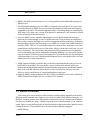
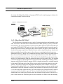
Now-a-days, we live in highly developed societies, where different technologies
are so well implemented that we don't spare a second thought. We have grown
accustomed to having many small gadgets and services performing every day
tasks. Never before has human kind had the opportunity and the means to travel,
while at the same time have almost unlimited access to a wide range of information. In the last decade, the amount of information and new services available to
the general public has exploded. This has happened so quickly, that even the
most wildest estimatimations of a few years ago now seem to have been very
conservative.
Although there has been an explosion in our mobility and information availability, these two factors have failed to merge successfully. This is mainly due to the
way information and services have been available. Because of the limitations of
the technology available until recently, it was impossible to take full advantage
of Internet-based information and services and at the same time being mobile. In
order to access the internet, it was necessary to use a land line phone, which basically took away the mobility factor while in use. However, wireless technology
has now reached a point where it is becoming possible to compete, in terms of
quality, with the more “traditional” PC-based web surfing and services. This is a
double edged sword for the wireless service providers. As wireless services are
still very much uncharted territories, the opportunities are limitless. However,
today's customers have been spoiled by technology. They are not easily
impressed, nor are they very loyal. For instance, the turn-over of subscriber
between different plans and subscribers has been registered to be as high as 30%.
Additionally, the increased demand for network capacity has been accompanied
by a significant decline in the average revenue per subscriber. This suggests that
basic wireless services such as, SMS, MMS, WAP, etc. have now become commodities.
The growing popularity of mobile communication devices, such as, cellular phones
and Personal Digital Assistants (PDAs) has paved way for location-based services
(LBS). LBS provides information to its users according to their location and pre-programmed preferences. This is a practical use of technology to solve everyday problems, holding a truly exciting future.
The aim of this project is to examine the benefits and viability of location-based service technology. Determining its usefulness, convenience, and to what degree it satisfies the information needs of its users. Tourist information guides, traffic reports,
weather forecast, local news and sport results are all examples of some of the services that could be provided by LOBIS-Location Based Information Service. The
service information could be delivered by several methods, such as, SMS and WAPpush to mention a couple.
Table Of Contents
Part 1
Introduction
CHAPTER 1
Introduction ......................................................................................1
1.1
1.2
1.3
1.4
1.5
1.6
Project Background.........................................................................2
Problem Definition ........................................................................2
Project Goals...................................................................................3
Definition of Terms.........................................................................4
Report Outline.................................................................................5
Project process and method ............................................................7
Part 2
Prestudy
CHAPTER 2
Communication Standards ........................................................11
2.1 Wireless Access Networks...........................................................12
2.1.1 Global System for Mobile Communications (GSM) ......................12
2.1.2 General Packet Radio System (GPRS) .......................................13
2.1.3 Universal Mobile Telecommunications System (UMTS) ................13
2.2 Location Technology and Services ...............................................15
2.2.1 Fundamentals of Mobile Location Services..................................16
Geographic Information Systems ...............................................16
Position Determining Equipment ...............................................17
The Mobile Positioning Center ..................................................19
Internet Gateway ....................................................................19
Internet-capable Mobile Devices ................................................19
Location-aware Technology ......................................................20
2.2.2 Location Services ...................................................................20
2.2.3 Location Management .............................................................20
2.3 Mobile Network Fundamentals ....................................................21
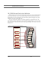
2.3.1 Omni cells and sector cells .......................................................21
i
Timing Advance .....................................................................22
Phone status: Idle / Busy- .........................................................22
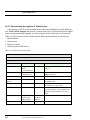
2.3.2 Effects of Cell Type and Size on Position Accuracyt .....................22
CHAPTER 3
Technologies ....................................................................................23
3.1 Short Message Service ( SMS) .....................................................24
3.1.1 SMS architecture and features ...................................................24
3.1.2 SMS Service Types .................................................................24
3.1.3 SMS user interface .................................................................25
Limitations of SMS ................................................................26
3.2 New Mobile Technology...............................................................27
3.2.1 Enhanced Messaging Service (EMS) .........................................27
EMS Background ...................................................................27
3.2.2 Multimedia Messaging (MMS) .................................................27
3.3 Mobile Terminals ..........................................................................29
3.4 WAP - Wireless Application Protocol .........................................32
3.4.1 Background to WAP................................................................32
WAP Forum..........................................................................32
3.4.2 WAP Architecture and overview ................................................32
How Does WAP Work? ...........................................................33
WAP Push ............................................................................34
Advantages with WAP .............................................................34
3.5 WML.............................................................................................35
3.6 Development Tools .......................................................................36
3.6.1 Nokia WAP Toolkit 3.0 ...........................................................36
3.6.2 Ericsson WapIDE SDK 3.2 .......................................................38
WapIDE Application designer ..................................................39
3.6.3 Ericsson WAP Gateway/Proxy 2.0 (EWGP) ................................39
3.7 JAWAP(the Java Application Framework) ...................................40
3.7.1 JAWAP Architecture ...............................................................40
The Servlet Class ....................................................................40
The Server Class .....................................................................40
The Session Class ...................................................................41
3.8 Server technology ........................................................................41
ii
3.8.1 Servlets................................................................................42
3.9 Parlay/ Open Service Access (OSA) ............................................43
Parlay API Specification ..........................................................43
The Parlay Mobility Interface ....................................................44
3.10 Incomit’s technology...................................................................45
3.10.1 Incomit ...............................................................................46
MOVADE™ Network Service Platform ......................................48
MOVADE™ Application Server ...............................................49
MOVADE™ Development Studio .............................................50
3.11 iWarf Service Creation Environment (SCE) ...............................51
3.11.1 E-SPA based application.........................................................51
3.11.2 The SLEE and SLEE services..................................................52
SLEE....................................................................................52
SLEE services ........................................................................52
CHAPTER 4
State-of-the-art ...............................................................................53
4.1 Overview of Different Types of Location Based Services ...........53
4.1.1 Location Based Services (LBS) .................................................53
Location based information .......................................................54
Location based billing ..............................................................54
Emergency services .................................................................54
Tracking ...............................................................................54
4.1.2 Looking into some type of services ............................................54
Buddy Finder .........................................................................55
“Hvor.no” .............................................................................55
Find the nearest ......................................................................56
Treasure Hunt ........................................................................56
End-User Services ..................................................................57
4.2 Market ...........................................................................................58
4.3 The future......................................................................................59
4.3.1 A day in the life of ..................................................................59
4.3.2 The challenges of the future ......................................................60
iii
CHAPTER 5
Technology Evaluation ................................................................61
5.1 Scenario & Solutions ....................................................................61
5.1.1 Scenario ...............................................................................61
5.1.2 Solutions...............................................................................62
SMS .....................................................................................62
WAP ....................................................................................63
MMS ....................................................................................63
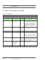
5.1.3 Technology Choice .................................................................64
5.2 Limitations ....................................................................................65
5.2.1 Location ...............................................................................65
5.2.2 Screen. .................................................................................65
5.2.3 Time ....................................................................................65
Part 3
Requirement Specification
CHAPTER 6
Requirements..................................................................................69
6.1 Overall System Description ..........................................................70
6.2 Functional Requirements ..............................................................71
6.2.1 Overall Use Case-LOBIS ........................................................71
6.3 Walkthrough of functional requirements: .....................................73
6.3.1 Use case 1 - Register user data ..................................................73
6.3.2 Use case 2 - Alter User Informations. ........................................75
6.3.3 Use case 3-Add/Remove User Service-Preference .........................76
6.3.4 Use case 4- Access Control ......................................................78
6.3.5 Use Case5 -Set LOBIS Service .................................................79
6.3.6 Use Case6 -Choose LOBIS Service ...........................................81
6.3.7 Use case 7 -Find Nearest .........................................................82
6.3.8 Use case 8 -Find Buddy ..........................................................85
6.3.9 Use case 9 -Tourist Information .................................................87
6.3.10 Use case 10- Advertisement ...................................................89
6.3.11 Use case 11 -Weather Information ...........................................92
6.3.12 Use case 12 Delete User .........................................................94
iv
6.4 Non-Functional Requirements ......................................................95
6.4.1 Usability ...............................................................................95
Ease of use (NFU-1) ................................................................95
Ease of learning (NFU – 2) .......................................................95
6.4.2 Efficiency Requirements ..........................................................96
Capacity requirements (NFP – 1) ..............................................96
6.4.3 Maintainability ......................................................................96
Server Maintenance (NFM – 1) .................................................96
Client Maintenance (NFM – 2) .................................................96
Backup (NFM – 3) .................................................................96
It should be easy to create independent clients for the system (NFM – 4)
97
6.4.4 Security ................................................................................97
Part 4
Design
CHAPTER 7
6.4.5 Documentation ......................................................................97
Client User Documentation (NFD – 1) ........................................97
6.4.6 Summary ..............................................................................97
Non-functional requirements summary ........................................98
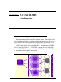
Overall LOBIS Architecture...................................................101
7.1 The LOBIS System .....................................................................101
7.2 System Architecture....................................................................102
7.2.1 Main System .......................................................................103
7.3 Database......................................................................................104
7.3.1 Database for Web and WAP ....................................................104
7.3.2 Database Class .....................................................................106
Class CDBManager ...............................................................106
7.3.3 Interface DBConstants ...........................................................107
7.3.4 Database in Incomit’s Platform................................................107
CHAPTER 8
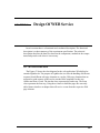
Design Of WEB Service ............................................................109
8.1 Servlet structure ..........................................................................109
v
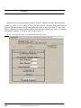
8.2 User Registration ........................................................................ 111
8.2.1 Functional description ........................................................... 111
8.2.2 Class RegisterServlet.............................................................112
Specification of method doPost() in class RegisterServlet: ............112
8.3 LoginHandler .............................................................................113
8.3.1 Functional description ...........................................................113
8.3.2 The class LoginHandler .........................................................113
Specification of method doPost in class LoginHandler: ................114
8.4 User Profile Admin .....................................................................115
8.4.1 Functional description ...........................................................115
8.4.2 The Class WLobisServlet .......................................................116
Specification of WLobisServlet ...............................................116
CHAPTER 9
Design of LOBIS service...........................................................117
9.1 LOBIS Service ...........................................................................117
9.1.1 Functionality description of LOBIS ..........................................117
Register Restaurants ..............................................................118
Find Location .......................................................................120
Find Nearest restaurant ..........................................................121
9.2 The servlet class “LobisServlet...................................................124
9.2.1 Summary of the description of class LOBIS ...............................126
CHAPTER 10
Design Of WAP service .............................................................127
10.1 Object Structure with server loading style................................128
10.1.1 WML Decks and Cards in class LobisSession...........................131
10.1.2 Functionality description of LobisSession ................................132
MakeFirstDeck .....................................................................133
Authorisation .......................................................................134
Make the ServiceDeck ...........................................................136
Connecting to the LOBIS Service ............................................138
10.1.3 Class LobisAppServer .........................................................139
10.1.4 Class LobisApp ..................................................................140
vi
Part 5
Implementation & Testing
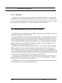
CHAPTER 11
Implementation............................................................................143
11.1 System Environment .................................................................143
J2SDK ................................................................................143
JDBC .................................................................................143
JSP ....................................................................................144
MySQL...............................................................................144
Tomcat ...............................................................................144
Rational Rose .......................................................................144
Modelator............................................................................145
11.2 Implementation of the LOBIS System......................................145
11.3 Comments for the Implementation ...........................................146
11.3.1 Finding Restaurant Information .............................................146
11.3.2 create a Table in iWarf .........................................................149
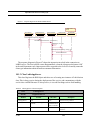
11.3.3 The Setup in the PATS lab at Telenor R&D ..............................150
Ericsson MPP ......................................................................150
11.3.4 Calculations on distances ......................................................152
CHAPTER 12
Testing .............................................................................................153
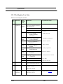
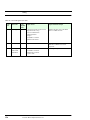
12.1 System Test Plan .......................................................................154
12.1.1 System Test Plan. ................................................................154
12.1.2 Test Register User Data ........................................................155
12.1.3 Test for Preferences .............................................................157
12.1.4 Test for alter user data ..........................................................158
12.1.5 WAP Test ..........................................................................159
12.2 Test Report ................................................................................160
12.2.1 The Web Test .....................................................................161
Register user data ..................................................................161
Add/Remove Preferences .......................................................162
12.2.2 The WAP Test ....................................................................163
12.3 Test Summary ...........................................................................164
vii
Part 6
User Manual
CHAPTER 13
User manual ..................................................................................171
13.1 LOBIS Web Service..................................................................171
13.1.1 Start site ............................................................................171
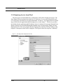
13.1.2 Registration of New User .....................................................172
13.1.3 user page ...........................................................................174
13.1.4 Alter user Information .........................................................174
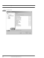
13.1.5 Add/ Remove Preferences ....................................................174
13.2 LOBIS WAP Service ................................................................178
Part 7Conclusion
CHAPTER 14
Discussion &Evaluation ............................................................185
14.1 Discussion .................................................................................185
14.2 Evaluation .................................................................................187
14.2.1 The method for the evaluation .............................................187
14.2.2 Work on the various phases .................................................187
Pre-study ............................................................................187
Evaliation of Technology .......................................................187
Requirements .......................................................................188
Construction .......................................................................188
Implementation....................................................................188
Testing ...............................................................................189
User's Guide and Installation Instructions .................................189
Project Result ......................................................................189
Usability on WAP phones.......................................................190
14.3 conclusion & Further work ......................................................190
14.3.1 Further Work .....................................................................190
14.3.2 Conclusion ........................................................................192
14.4 Personal Experience..................................................................192
viii
Part 8References & Glossary
CHAPTER 15
References & Glossary ..............................................................197
15.1 References.................................................................................197
15.2 Glossary ....................................................................................203
Appendix A
Requirement Summary..............................................................1A
Appendix B
Rational Unitified Process ........................................................ 1B
2.1 What is a Software Engineering Process ..................................... 1B
2.1.1 Process Components .............................................................. 2B
2.1.2 Lifecycle Structure................................................................. 3B
Inception Phase ..................................................................... 4B
Elaboration Phase ..................................................................4B
Construction Phase ................................................................. 4B
Transition Phase ....................................................................4B
2.1.3 Process Architecture .............................................................. 4B
2.1.4 Iterations.............................................................................. 5B
Appendix C
iWarf Overview ............................................................................1C
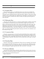
3.1 iWarf IDE Overview ....................................................................1C
3.1.1 The Explorer:........................................................................2C
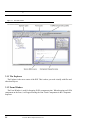
3.1.2 Form Window .......................................................................2C
3.1.3 Component Inspector .............................................................3C
3.1.4 Source Editor ........................................................................3C
3.1.5 E-SPA Component Palette .......................................................4C
Call Control Component .........................................................4C
User Location component ........................................................4C
Messaging Component ............................................................5C
User Status Component ...........................................................5C
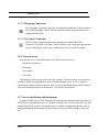
3.1.6 Network Access ....................................................................5C
ix
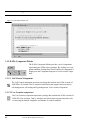
3.1.7 Service installation and deployment ..........................................5C
3.1.8 Deploying Service from iWarf..................................................7C
Appendix D
WML ................................................................................................1D
4.1 WML elements ............................................................................1D
4.2 JAWAP is the Facilitator to produce WML .................................5D
Appendix E
A simple introduction to Modelator 4.0 ............................... 1E
5.1 Modelator Notation...................................................................... 1E
5.1.1 Primary key .......................................................................... 4E
5.1.2 Rules................................................................................... 5E
Appendix F
UML Notation ............................................................................... 1F
6.1 The UML Notation ...................................................................... 1F
6.1.1 Notation for Use Case Diagram ................................................ 1F
6.1.2 Notation Sequence diagram ..................................................... 2F
6.1.3 Notation Statechart Diagram .................................................... 3F
6.1.4 Notation for the Class Diagram ................................................ 3F
Appendix G
JAVADOC ...................................................................................... 1G
JAVADOC
JAVADOC
JAVADOC
JAVADOC
JAVADOC
JAVADOC
JAVADOC
JAVADOC
LOBIS ............................................................................ 3G
LobisServlet ................................................................... 9G
WlobisServlet ............................................................... 13G
LoginHandler ............................................................... 17G
LobisAppServer ........................................................... 19G
LobisApp...................................................................... 23G
LobisSession................................................................. 27G
DBConstants................................................................. 31G
x
JAVADOC CDBManager ............................................................... 37G
Appendix H
JAVA Source ................................................................................. 1H
PACKAGE
PACKAGE
PACKAGE
PACKAGE
Com/mycompany/test.................................................... 3H
jawap ............................................................................. 5H
Lobis.............................................................................. 7H
Paraworld....................................................................... 9H
xi
xii
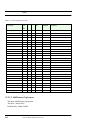
List Of Figures
Figure 1
Figure 2
Figure 3
Figure 4
Figure 5
Figure 6
Figure 7
Figure 8
Figure 9
Figure 10
Figure 11
Figure 12
Figure 13
Figure 14
Figure 15
Figure 16
Figure 17
Figure 18
Figure 19
Figure 20
Figure 21
Figure 22
Figure 23
Figure 24
Figure 25
Figure 26
Figure 27
Figure 28
Figure 29
Figure 30
Figure 31
Figure 32
Figure 33
Figure 34
Figure 35
Figure 36
A graphical view of the problem definition ...................................................... 3
Structure of the thesis ....................................................................................... 6
GPRS and GSM Phone................................................................................... 13
UMTS Phone ................................................................................................. 14
Position determination, location managment, and WLS. ................................ 16
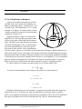
Cell site/sector information for positioning the mobile user. ........................ 18
Example of cells and cell-plan. ....................................................................... 21
The four representation of the phone location (dark area) .............................. 22
Push and Pull services .................................................................................... 25
Example of SMS phone.................................................................................. 26
Example of MMS phone ................................................................................ 28
Mobile Terminals........................................................................................... 30
Example of MMS Phone that shows a advertisement ................................... 31
WAP Phone R380 for GSM............................................................................ 31
The Wprld Wide Web model.......................................................................... 33
The WAP model ............................................................................................. 34
Toolkit and Simulator ..................................................................................... 37
n the WapIDE the windows switches to the selected device.......................... 38
WapIDE Application designer......................................................................... 39
Logic distribution across three machines ........................................................ 41
Client to Servlet.............................................................................................. 42
Example of area defination............................................................................. 45
Incomit’s MOVADE copyright Incomit .......................................................... 47
Overview of MOVADE Network Service Platform ....................................... 48
Overview of MOVADE Application Server.................................................... 49
iwarf main window.......................................................................................... 50
example of small-scale map from application
”hvor.no” on http://www.wap.hvor,no............................................................. 56
Norwegian version:pit.treasuremachine.com ................................................. 57
Overall system view. ....................................................................................... 70
A overall use case for LOBIS.......................................................................... 72
Register user data ............................................................................................ 73
Alter user data................................................................................................. 75
Add/Remove user service-preference............................................................. 76
Access control for WAP and Web. .................................................................. 78
Use case 5 Set LOBIS services ....................................................................... 79
Choose LOBIS Service.................................................................................... 81
xiii
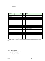
Figure 37
Figure 38
Figure 39
Figure 40
Figure 41
Figure 42
Figure 43
Figure 44
Figure 45
Figure 46
Figure 47
Figure 48
Figure 49
Figure 50
Figure 51
Figure 52
Figure 53
Figure 54
Figure 55
Figure 56
Figure 57
Figure 58
Figure 59
Figure 60
Figure 61
Figure 62
Figure 63
Figure 64
Figure 65
Figure 66
Figure 67
Figure 68
Figure 69
Figure 70
Find Nearest ................................................................................................... 82
Find Buddy...................................................................................................... 85
Tourist Information ......................................................................................... 87
Use case 10 Advertisement .......................................................................... 90
weather ............................................................................................................ 92
Use case 12 -Delete User ............................................................................... 94
LOBIS component structur .......................................................................... 101
The figure shows the system structure ......................................................... 102
Overall Class Diagram .................................................................................. 103
Database Tables............................................................................................ 104
Class Diagram for Web service......................................................................110
Cite map over the LOBIS WEB service. .......................................................111
User Register.................................................................................................112
Loginhandler ..................................................................................................113
Statechart Diagram for WLobisServlet..........................................................115
The Tasks in LOBIS Service.........................................................................118
Sequence diagram for Register Restaurant information ...............................119
Sequence Diagram for getLocation (in Class LOBIS).................................. 120
Sequence Diagram for CircleAlg (in Class LOBIS) .................................... 121
Description of circle Algorithm ................................................................... 122
Sequence Diagram for CircleAlg and Find Location.................................... 124
The connection between the LOBIS service and servlet .............................. 125
loading with the server-class in JAWAP framework..................................... 127
Object structure ............................................................................................ 129
Class Diagram for WAP Application ........................................................... 130
ServiceDeck overview from class LobisSession. ......................................... 131
Sequence Diagram for authorisation............................................................ 135
Overview of function ServiceDeck ( ) ......................................................... 136
Sequence Diagram for ServiceDeck ............................................................. 137
Http connection to the LOBIS service in iSea environment ........................ 138
A sequence Diagram for the RestaurantDeck function................................ 139
Restaurant information search on Maponweb ............................................. 147
A converting between degrees on decimal
format and degree-minutes-seconds............................................................. 148
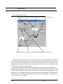
Illustration the environment in the lab where the LOBIS service will run. .. 151
xiv
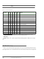
Figure 71
Figure 72
Figure 73
Figure 74
Figure 75
Figure 76
Figure 77
Figure 78
Figure 79
Figure 80
Figure 81
Figure 82
Figure 83
Figure 84
Figure 85
Figure B1
Figure B2
Figure C3
Figure C4
Figure C5
Figure C6
Figure C7
Figure C8
Figure D9
Figure E10
Figure E11
Figure E12
Figure F13
Figure F14
Figure F15
Figure F16
Figure F17
Figure F18
Start Page ...................................................................................................... 172
Registration form example............................................................................ 173
User page....................................................................................................... 174
confirmation about saved data ...................................................................... 175
Add/remove preference................................................................................. 176
set preferences............................................................................................... 177
Invalid Password (Access Denied) page ....................................................... 178
LOBIS First Card .......................................................................................... 179
WAP Login Card ........................................................................................... 179
Insert GSM number....................................................................................... 180
Insert GSM Number...................................................................................... 180
Insert password ............................................................................................. 180
Welcome Message......................................................................................... 181
choose Services ............................................................................................. 181
Restaurant information.................................................................................. 182
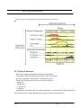
Software Engineering Process ........................................................................2B
The process is organized both in time (phases), and
content (process components). ........................................................................3B
iwarf main window .......................................................................................2C
Component Inspector ....................................................................................3C
Source Editor in iWarf SCE. ..........................................................................4C
SLEE manager’s main window.......................................................................6C
Easy Deploy Wizard: Deployment, File Tab ..................................................7C
Easy Deploy Wizard: .....................................................................................8C
The Element hierarchy of WML.....................................................................4D
Modelator main window ................................................................................ 2E
Relationship type properties........................................................................... 3E
Entity properities............................................................................................ 4E
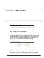
Actors and Use case ........................................................................................ 1F
Example for Sequence diagram ...................................................................... 2F
Triggerless Transition...................................................................................... 3F
Class ............................................................................................................... 4F
Generalization ................................................................................................. 4F
Note................................................................................................................. 4F
xv
xvi
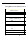
List Of Tables
Table 1:
Table 2:
Table 3:
Table 4:
Table 5:
Table 6:
Table 7:
Table 8:
Table 9:
Table 10:
Table 11:
Table 12:
Table 13:
Table 14:
Table 15:
Table 16:
Table 17:
Table 18:
Table 19:
Table 20:
Table 21:
Table 22:
Table 23:
Table 24:
Table 25:
Table 26:
Table 27:
Table 28:
Table 29:
Table 30:
Table 31:
Table 32:
Table 33:
Table 34:
Table 35:
Table 36:
Summary of the different solutions ........................................................................ 64
Description of use case 1-Register user data .......................................................... 74
Description of requirements for Use case 1-Register user data.............................. 74
Description of use case 2 Alter user data................................................................ 75
Description of requirements for use case 2 -Alter user data................................... 76
Description of use case 3 Add/Remove user service-preference............................ 77
Description of requirements for
Use case 3-Add/Remove user service-preference ................................................. 77
Description of use case 4- Access Control ............................................................. 78
Description of requirements for Use case 4-Access Control................................. 79
Description of use case 5 -Set LOBIS Services...................................................... 80
Description of requirements for Use case Set LOBIS service................................ 80
Description of use case 6- Choose LOBIS Service ................................................ 81
Description of requirements for Use case 6 Choose LOBIS service...................... 82
Description of use case 7 -Find Nearest Service .................................................... 83
Description of requirements for Use case 7-Find Nearest Service......................... 84
Description of use case 8- Find Buddy. .................................................................. 86
Description of requirements for Use case 8- Find Buddy....................................... 86
Description of use case 9 -Tourist Information ...................................................... 88
Description of requirements for Use case 9 -Tourist Information .......................... 88
Description of use case 10 -Advertisement. .......................................................... 91
Description of requirements for Use case 10- Advertisement................................ 91
Description of use case 11 -Weather Information.................................................. 93
Description of requirements for Use case 11- Weather. ......................................... 93
Description of use case 12 - Delete User................................................................ 94
Description of requirements for Use case 12- Delete User..................................... 95
Summary of Non-functional requirements ............................................................. 98
Entity type list. Id = Primary Key, Req = The requirement for the Attributes ..... 105
Relationship type list. ........................................................................................... 105
Function description of Class CDBManager........................................................ 106
Description of Interface DBConstants................................................................. 107
Table description in Slee_db database “ restaurant_service” .............................. 108
class RegisterServlet............................................................................................ 112
Class LoginHandler .............................................................................................. 114
Class WLobisServlet ............................................................................................ 116
A brief description of the function register_Restaurant( ).................................... 119
A brief description of the function getLocation in class LOBIS ......................... 120
xvii
Table 37:
Table 38:
Table 39:
Table 40:
Table 41:
Table 42:
Table 43:
Table 44:
Table 45:
Table 46:
Table 47:
Table 48:
Table 49:
Table 50:
Table 51:
Table 52:
Table 53:
Table A1:
Table D2:
Table E3:
A brief description of the CircleAlg( ) ................................................................. 122
Class LobisServlet............................................................................................... 125
Class LOBIS summary......................................................................................... 126
LobisSession Class Description .......................................................................... 132
Parameter description of Paragraph in JAWAP.................................................... 133
LobisAppServer Class Description ...................................................................... 139
LobisApp Class Description................................................................................. 140
The packages and their content in the LOBIS system ......................................... 146
System Test Plan .................................................................................................. 154
Test for Register User Data .................................................................................. 155
Test for Add/Remove ........................................................................................... 157
Test for the Alter User data .................................................................................. 158
Test for the WAP device....................................................................................... 159
Test Table ............................................................................................................ 160
Test for Register User Data .................................................................................. 162
Test for Add/Remove Preferences........................................................................ 163
Test for the WAP device....................................................................................... 164
Summary of functional requirement ......................................................................1A
WML elements implementation status...................................................................5D
Rules....................................................................................................................... 5E
xviii
Part 1
Introduction
The need to always be available, and to have access to information regardless of location is ever increasing. This has lead to
the mobile phone becoming an indispensable tool for anyone who
praises mobility and independence. The introduction of Location
Based Information Services (LOBIS) has added an entirely new
dimension to mobile telefony. Through the use of LOBIS, the
user has access to a wide range of information and services that
are location specific to the user's position. This part of the thesis
is an overview defining the problems dealt with, the goals and
describing the most important terms used in this report.
1
2
CHAPTER 1
Introduction
“We need devices and services to became aware of their location, both in space and time, especially if
they are mobile” Bill Joy, chief scientist. Sun Microsystems.
The information available on the Internet is becoming increasingly relevant to
our daily life. Restaurant guides, local maps, public transport information and
weather reports are examples of the information currently available on the web. The
new developments in mobile computing have enabled us to access the Internet even
outside the confines of our office and home. A service and methodology for utilising
the relevant local specific information on mobile devices is, therefore, needed.
The central element in the emerging market of location-based services (LBS) is
location. As the name implies, LBS provides information relevant to the geographical location of the mobile device. Knowledge on position is essential for several
business areas, such as, fleet tracking, transport, logistics and other business areas
bases on knowing the location of someone or something. For instance, someone at a
shopping mall calling on for the nearest economy-budget restaurant, needs only the
names and addresses of those restaurants which are within his reach.
Unconsciously, most people organise their lives according to geospatial considerations [3]. When considering which movie to see or where to eat people will make
decisions based on their location and which option are the most convenient. Proximity to home, work or current location is often a defining factor of what is convenient.
This tendency to think in geographical terms makes it very sensible to deliver information and services centered on location. I.e. service and information providers
deliver location-sensitive information.
This study will discuss and evaluate the methods in user-location detection, and
provide methods of how to implement the service in a wireless personal communication system.
This chapter describes the problems discussed and the project goals. It also gives
an explanation of relevant terms.
1
Introduction
1.1 Project Background
The Internet now has 350 million users. It is expected to be 3 billion mobile phones worldwide in 2004, and 1/10 of these will have Internet access and be attached to powerful computers
(source: IDC). More and more companies are therefore working as virtual organizations, where
people are distributed over several locations and time zones.
This project is part of Telenor Research & Development (R&D) and Mobile Work Across Heterogeneous Systems (MOWAHS). As part of an European research project (Eurescom
P1110:OSA Assessment) is performing an evaluation of a service platform developed by a Swedish company, Incomit AB. MOWAHS is a basic research project supported by the Norwegian
Research Council in its IKT-2010 program. The project is carried out jointly by the IDI's groups
for software engineering and databases at the Norwegian University of Science and Technology,
Department of Computer and Information Science which started July 2001. The work of the
MOWAHS project has its root in an earlier project at IDI called Cooperative Agents in a Global
Information Space (CAGIS) [4]. An overall objective for the latter was to offer a generic platform for e.g. concurrent engineering. That is, CAGIS is supporting IT based cooperation among
humans who are geographically differently located. The initial objectives of the MOWAHS
project are twofold: to support mobile work process and to support transaction for mobile users
across different platforms.
1.2 Problem Definition
The problem definition of this project is the following:
“To analyse, design and implement a service “LOBIS-Location Based Information Service”,
that offers information in shape of text, image, and audio to the users with mobile terminals.”
This project will implement, analyses, and design a service which provide information to the
end-user. The service utilize methods like SMS, WAP, and MMS to deliver information to the
end-user.
2
Location Based Information Service
Project Goals
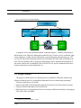
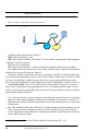
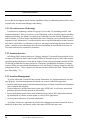
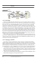
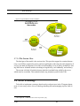
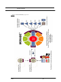
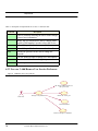
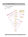
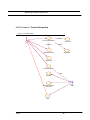
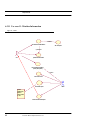
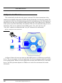
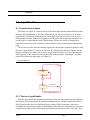
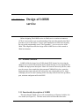
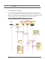
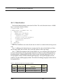
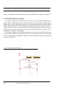
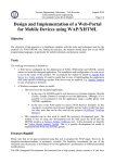
Figure 1A graphical view of the problem definition
LOBIS
Location Based Informtion Service
Restaurant
tourist info.
Information
arrangement
Kind of information
User Preferance
advertisement
User Profile
WAP
WAP
SMS
Internet/
Web
MMS
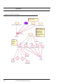
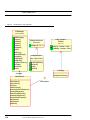
A graphical view of the problem definition is shown in Figure 1 LOBIS Location Based
Information service finds area information around the user’s location, such as restaurant, sightseeing, pharmacy, weather forecast information, tourist information, advertisement, etc. The
service will deliver the information with the aid of methods like WAP, SMS, and MMS to the
User. The user should be able to specify his personal preferences about the information he or
she desires with the aid of method like Web or WAP. The user specify information like advertisement information, tourist information, etc.
1.3 Project Goals
The purpose with this thesis is to illustrate theory, possibilities, difficulties and practical
solutions within the area of Location Based Information Services and mobile positioning.1
The aims of this thesis is four-fold:
1.
2.
3.
Study of what kind of information that might be provided to users based on their location.
Study all related technologies based on location.
Make an overview of location based services currently available on the market, focusing specially SMS, WAP, and MMS.
1.Geographical positioning of mobile terminals.
LOBIS
3
Introduction
4.
Take a in-depth look at the developing tools provided by Incomit's service platform, followed
by an analysis, design and prototyping of part of a location-Based system.
1.4 Definition of Terms
It is important to understand the most important terms used in this project. In this section the
terms will be clarify. The most important terms are the following
Location based services: This is an application that will allow mobile users to receive personalized and lifestyle-oriented services relative to their geographic location. These services use the
positions (coordinates) provided from a Mobile Location System [1].
Mobile Location System: A system that has support for location of GSM subscribers based
on one or many Geographic Positioning Technologies. It also handles roaming, charging/billing
and subscriber privacy management. Many different techniques can be combined in a Mobile
Location Systems.
Network based: This technology does not require new mobile equipment so it will be available to all members in all GSM networks from day one that the technique are installed.
Mobile Phone: A mobile phone allows the user to make wireless phone calls. The mobile
phones have many features one can find synonyms like cellular phone wireless phone. Sometimes
only user- phone is used.
User: In this project, a Web user is a person that accesses the location based information service via a Web browser and a WAP user is a person that accesses the location based information
service via WAP device.
LOBIS: Location Based Information Service (LOBIS). In this project, The system called
LOBIS, and the service which created in the Incomit’s platform is called LOBIS service.
PDA: Personal Digital Assistant, PDA is a combination of a digital calendar, address books
and services such as e-mail, SMS and Internet. Handheld is a synonym.
Smart Phone: A smart phone is a combination of a mobile phone and a PDA.
4
Location Based Information Service
Report Outline
1.5 Report Outline
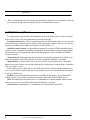
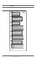
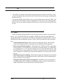
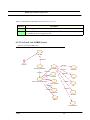
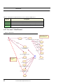
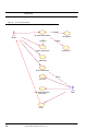
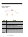
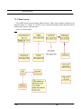
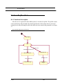
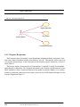
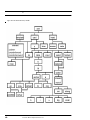
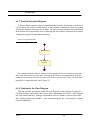
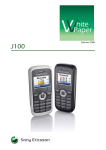
This thesis is divided in seven parts including Introduction. The out line of the thesis is summarized in the Figure 2
Part 2 “Pre-study” is a representation of preliminary studies on Location-based information.
This part includes two chapters, chapter one: a general introduction to Mobile Positioning Technology and; Chapter two: a general introduction to the existing location based services.
Part 3 “Requirements” This part includes CHAPTER 6 that consists of Functional and NoneFunctional requirement imposed to the LOBIS System
Part 4 “Design” This Part includes CHAPTER 7 which consist of overall LOBIS architecture
design,CHAPTER 8 consists of Web application design, CHAPTER 9 consists of LOBIS service(iSea) design and finally CHAPTER 10 consists of WAP application design.
Part 5 “Implementation & Testing” The implementation of LOBIS system described in this
part. The Part also includes a test for the system
Part 6 “User Manuel” This part describe the necessary steps to run the prototype.
Part 7 “Conclusion” which includes CHAPTER 14 “Discussion & Evaluation” provides a
discussion and evaluates the prototype.
Part 8 “References & Glossary”, this part consist of CHAPTER15 provides a list of the references and a list of Glossary. It also includes Appendix A “Requirement summary” provides a
summary table of all the functional requirement for LOBIS System, Appendix B gives an overview of Rational Unitified Process, which has been used in this thesis, Appendix C gives a brief
overview of iWarf service creation environment, Appendix D gives a description of WML elements, Appendix E describe a simple introduction to Modelator 4.0, Appendix F describes some
of the UML notation which has been used in this thesis, Appendix C includes the JAVADOC
and finally Appendix H includes the JAVA source.
LOBIS
5
Introduction
Figure 2 Structure of the thesis
P a r t 1 I n t r o d u c t io
n
C h a p te r 1
I n t r o d u c t io n
Thesis
P a rt2
P re s tu d y
C h a p t e r 1 C o m m u n ic a t io n
S ta n d a rd s
C h a p t e r 3 T e c h n o lo g ie s
C h a p t e r 4 S o lu t io n s
P a rt 3
R e q u ir e m e n t
C h a p te r 5
R e q u ir e m e n t
P a rt 4
D e s ig n
C h a p t e r 6 O v e r a ll L O B I S
A r c h it e c t u r e
C h a p t e r 7 W e b D e s ig n
C h a p t e r 8 D e s ig n o f L O B I S S e r v ic e
C h a p t e r 9 D e s ig n o f W A P S e r v ic e
P a r t 5 I m p le m e n t a t io n &
D e s ig n
C h a p te r 1 0
I m p le m e n t a t io n
C h a p t e r 1 1 T e s t in g
P a rt 6
D e s ig n
C h a p t e r 1 2 C o n c u lu t io n & f u r t h e r
w o rk
C h a p t e r 1 3 R e f e r e n c e s & G lo s s a r y
P a r t 7 C o n c lu s io n
C h a p t e r 1 4 D is c u s s o n & E v a lia t io n
P a r t 8 R e f e r e n c e s & G lo s s a r
C h a p t e r 1 5 R e f e r e n c e s & G lo s s a r y
A p p e n d ix A
A p p e n d ix B
A p p e n d ix c
A p p e n d ix D
A p p e n d ix E
A p p e n d ix F
6
Location Based Information Service
Project process and method
1.6 Project process and method
The goal of every development process is to create some sort of product to solve some problems or perform some tasks. The development methodology chosen for the project is the RUP
model which described in Software Engineering Standards [64] The Appendix B gives a brief
overview of RUP.
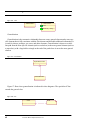
There are usually five stages in this model of software development:
1. Requirements In this stage the requirements of the “to be developed software” are established. These are usually the services it will provide, its constraints and the goals of the software. Once these are established they have to be defined in such a way that they are usable in
the next stage. This stage is often preluded by a feasibility study or a feasibility study is
included in this stage. The feasibility study includes questions like: should we develop the
software, what are the alternatives? It could be called the conception of a software product
and might be seen as the very beginning of the life cycle.
2. Analysis & Design: The goal of the Analysis & Design workflow is to show how the system
will be realized in the implementation phase. In this stage the established requirements, flowing from the first stage, are identified as software or hardware requirements. The software
requirements are then translated in such a way that they can be readily transformed into computer programs. A system should be build with a robust and dynamic structure, so that it willendure high user loads and be easy to add new functionality.
3. Implementation: The purpose of implementation are to define the organization of the code, in
terms of implementation subsystems organized in layers, to implement classes and objects in
terms of components (source files, binaries, executable and other), to test the developed components as units. and to intergrate the results produced by individual implementers, into an
executable system.
4. Testing: The purposes of testing are to verify the interaction between objects. to verify the
proper integration of all components of the software, to verify that all requirements have
been correctly implemented, and to identify and ensure defects are addressed prior to the
deployment of the software.
5. Deployment: The purpose of the deployment workflow is to successfully produce product
releases, and deliver the software to its end users.
The purpose of this project is to develop a prototype. This prototype is only ment for internal
use at Telenor R&D and MOWAHS project at IDI. Therefore the last deployment phase mentioned above is a minor matter of deploying the prototype at Telenor R&D and MOWAHS
LOBIS
7
Introduction
project at IDI. With this limited target there is no need for a complex deployment strategy. Therefore it is no further elaboration on this phase.
8
Location Based Information Service
Part 2
Prestudy
This Part describes the prestudy done in the diploma thesis.The first chapter gives an overview of the communications
standards and the second chapter give an overview of the location
based technologies Since this is a very young and changing technology there is a lack of printed literature on the market. Therefore much of the background material for this report had to be
found on the Internet.
9
10
CHAPTER 2
Communication
Standards
The objective of this chapter is to give the reader a quick overview of mobile
positioning services and technology and their characteristics.
“We need devices and services to become aware of their location, both in space and time, especially if they are
mobile.” Bill Joy, chief scientist, Sun Microsystems
“Location services combine GIS applications with easy-to-use mobile devices to provide information wherever
and whenever it is needed. The GIS technology behind these services will empower an increasingly diverse range
of applications, putting even more valuable information in the hands of mobile users.” Jack Dangermond, president, ESRI
Mobile comerce services utilise location-based services to gather information
about the current location position of the user of a mobile device. Location-based
services are applications that deliver location-based information wherever and
whenever necessary. Location-based services have been around since the 1990's,
with the earliest applications being used for auto-theft prevention and recovery.
Lojack being one of the examples of the earliest applications. Since the second half
of the 1990's, GPS-based systems have become more wide spread. Fleet tracking,
emergency dispatches, navigation, stolen vehicle recovery and roadside assistance,
to name a few, are examples of GPS-based applications.GPS users can access these
services through a variety of means. Such as, via their desktop, web-browser, mobile
phone, personal digital assistant (PDA) and several other devices.
11
Communication Standards
2.1 Wireless Access Networks
This section gives an overview over existing wireless networks available today. Global System
for Mobile Communications (GSM) and its radio access network are introduced. Understanding
of GSM and especially its radio access network is important in order to easier understand the
GSM based technology.
Today, existing digital mobile networks in Europe are based on the international recognized
GSM standard now deployed in most countries of the world. The GSM Association recently
announced that there are now more than 500 million global GSM customers in the world (nearly
70 percent of the world's digital wireless market). GSM, which has evolved over the past 15
years, was developed with speech in mind as the main application and is thus circuit switched due
to its real time nature. However, new services have been added over the years and today GSM
offers short text messages, Wireless Application Protocol, circuit switched data transfer and positioning services. All these services though, are based on the circuit switched radio access interface
of GSM, allowing for only one user per channel, limiting user bandwidth and the number of parallel users accessing the network. However, all this is now changing with the introduction of three
new enhancements of the existing GSM infrastructure: HSCSD allowing for higher bit rates for
circuit switched data, GPRS introducing packet switching and EDGE introducing new modulation techniques on the radio interface and thus higher bit rates available for GSM data and GPRS
[7].
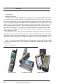
2.1.1 Global System for Mobile Communications (GSM)
In 1982 the Conference of European Posts and Telegraphs formed a study group called the
Groupe Special Mobile (GSM) to investigate and develop a European public and mobile system
(PLMN). In 1989 the responsibility was transferred to the European Telecommunication Standards Institute (ETSI) and the first GSM specifications (Phase 1) was published in 1990. The first
commercial service was available in 1991 and today GSM accounts for more 500 million subscribers worldwide.
In 1998 the 3rd Generation Partnership (3GPP) was founded to develop standards for a new
generation of mobile networks based on the new Universal Terrestrial Radio Access Network
(UTRAN) and an evolved GSM network. This new technology is referred to as UMTS in Europe.
UMTS is one of many technologies defined by the International Telecommunication Union (ITU)
for enabling third generation mobile networks (3G).
Since UMTS is based on reuse of existing GSM infrastructure the responsibility for the GSM
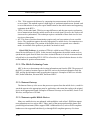
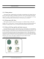
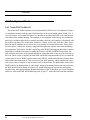
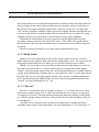
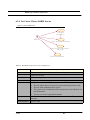
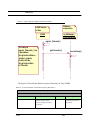
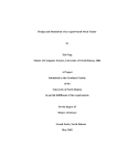
standards was transferred to 3GPP in 2000. The Figure 3 shows a GSM-Phone.
12
Location Based Information Service
Wireless Access Networks
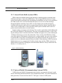
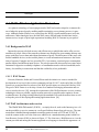
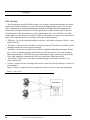
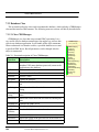
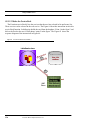
2.1.2 General Packet Radio System (GPRS)
GPRS connects the Mobile Station to the Internet by introducing packet switching in the
GSM network (Figure 3 shows the GPRS Phone). The existing GSM infrastructure is maintained, but the packet switching traffic and signaling are handled by two new servers installed in
the GSM network. The circuit switched data and speech services are not affected and go
through the Mobile Switching Center (MSC) as usual. Both circuit switched and packet
switched traffic share the same radio access network until the Base Station Controller (BSC)
where circuit switched traffic is sent to the MSC and the packet switched traffic to the new
packet network and from there on to the Internet.
Imagine reading a newspaper on the Internet. First we take a quick look on the headlines and
the click on the link that we find interesting. The page is downloaded and then we read it. During the reading no data is sent between the device and the newspapers server, thus rendering the
14.4 Kbps timeslot free to use for other subscribers. This is exactly what GPRS does. Many
users share regular GSM timeslots, when one user is reading another can use the same timeslot
to download his or hers data. Even though many users share the timeslots the user perceives
packet service as a dedicated connection always available. When initiating a GPRS session the
Mobile Station receives a temporarily IP address which is kept until the GPRS connection or
Mobile Station is turned off. During the session the Mobile Station is always connected to the
Internet, i.e. it is always on [7]
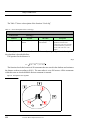
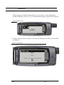
Figure 3 GPRS and GSM Phone
GPRS
Phone
GSM Phone
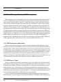
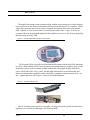
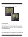
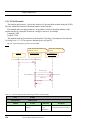
2.1.3 Universal Mobile Telecommunications System (UMTS)
UMTS (Universal Mobile Telecommunications System) was proposed as Europe’s candidate for IMT-2000 (International Mobile Telecommunications 2000) – the official standard for
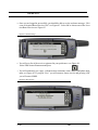
third generation (3G) networks from the ITU. The Figure 4 shows a UMTS phone
LOBIS
13
Communication Standards
Two things have prevented a unified approach to a single 3G standard: - spectrum allocation
and network enabling technologies. On the spectrum allocation front, back in 1992 the World
Administrative Radio Conference (WARC) allocated spectrum around the 2 GHz band for terrestrial and satellite services. Europe put the second set of GSM networks at 1800 MHz (Orange,
One2One and Virgin in the UK) which is sufficiently far away not to interfere with the 2 GHz
band. However, in the USA the 1900 MHz band has been adopted for what the Americans have
termed PCS (Personal Communications Services) networks. Unfortunately, 1900 MHz equates to
1.9 GHz – too close to 2 GHz for comfort. So the ITU agreed a compromise where a whole range
of different frequencies could be used for 3G. Hence the dream of everyone using 3G around the
2.1 GHz band disappeared.
Next came problems with the which systems to use to build a 3G network. The EEC wanted to
repeat its success with a GSM for 3G networks so it came up with UMTS. As a result of yet
another compromise (this time between mainly European and Japanese manufacturers), a technology called Wideband CDMA (W-CDMA) became the official means for implementing UMTS.
Although the ITU has accepted UMTS as an official standard for 3G, it also adopted two other
standards: – CDMA2000 backed mainly by the USA and Korea, plus TD-SCDMA (Time Division- Synchronous CDMA) an outsider but invented by China, the biggest single market for
mobile. [6] The Figure 4 shows a UMTS phone.
Figure 4
14
UMTS Phone
Location Based Information Service
Location Technology and Services
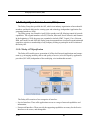
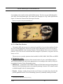
2.2 Location Technology and Services
Imagine yourself coming alone to a big city that you have never been to before. It is late and
the only thing you want to do is to go to a trendy club where all the cool guys hang out. Since
this is your first time in this city, you have no idea of where to go. All you know is that these
guys listen to "coolMusic" which happens to be your favorite music as well. These guys tour
various clubs playing "coolMusic" during the evening and night and of course you want to join
them. "But where are they" you ask yourself. Without a second thought you grab you mobile
out of you pocket and key-in "find coolMusic group". A couple of seconds later you have the
answer. The "coolMusic" guys are just a couple of blocks away. Near a club you passed by earlier. "Time to party!", you tell yourself.
Information on location plays a central role on how people organise themselves and relate to
their surroundings. In an information-based society, we value systems and services that provided us with information about the location of people, objects, and phenomena. This is evident
from the content of most currently available databases. They usually provide us with information related to location or geographic components. Simply knowing where you are, or how far
you are from someone or something, is normally of little value. For instance, knowing that you
one mile away from a particular facility may give you some small comfort that you getting
closer to that point. Having a travel path on how to get there, adds value to the information on
location. The more valid and reliable information on how to get there, the more valuable it
becomes. Additional information on stores and potential customer along that route, may
enhance the value even further. Having the possibility to modify the recommended route to
avoid delays due to construction works or traffic incidents adds yet another level of value.
Perhaps the single factor that sets mobile communications apart from all other forms of telecommunication is location. In mobile communications, where you are is important. Services
based on mobile location, otherwise known as Wireless Location Services (WLS) [11], provide
a mobile operator with a means of differentiation that can not be matched by fixed telecommunications. To have an understanding and appreciation of WLS, one must also understand the
underlying technologis behind WLS.
Location technology and services are all about the ability to pinpoint the position of a mobile
user, mange the location data associated with the user. Put that data into context so that it
becomes useful information, and apply services based on that information (see Figure 5 )
The below figure depicts the relationship between position determination, location management, and WLS.
LOBIS
15
Communication Standards
Figure 5 Position determination, location managment, and WLS.
Position
Determination
Applications
Emergency
services
Cell/sector
Location
AOA
Sensitive
Location
Management
Provisioning
User
Interface
Billing
Location
based
info.
TDOA
Tracking
Services
GPS
E-OTD
GIS
DATA
others
TOA
Figure 5 . has been taken from "Wireles Intelliget Network" [11]. All elements in the figure
will be described in the Section 2.2.1
2.2.1 Fundamentals of Mobile Location Services
A few key technologies are importent to mobile location. Mapping concepts will be discussed
in section 2.2.1.1, for with out their could be no relevance in location.
2.2.1.1 Geographic Information Systems
The term geographic information system (GIS) applies to computer-based tools for electronically mapping and analyzing real things and associated events. GIS can be used for visualization
of information as well as decision making. GIS is a very important aspect of any location technology. GIS approaches provide a quick fix for WLS call processing, they are less efficient and
effective than network-based call processing. The ideal architecture will have call processing
algorithms built into the WLS applications themselves with GIS provisioning and administration
as a separate interface (as depicted in Figure 5 ). For more information se referese [11] In addi-
16
Location Based Information Service
Location Technology and Services
tion a wireless networ, the following location-based network technologies are required in order
to provide Mobile Location Services :
Position Determining Equipment
2. Mobile Positioning Center
3. Internet Gateway
4. Internet-capable Mobile Devices
5. Location-aware Technology
The next sections (2.2.1.2.-2.2.1.6.) will give a brief description of the five location-based
network technologies .
1.
2.2.1.2 Position Determining Equipment
When most people think about position determination, global positioning system (GPS) is
the first technology that comes to mind. GPS uses satellites in a geosynchronous orbit for determining the exact position of a device. Many of the early location services, such as, telematics
use this technology. While GPS is an important resource for position determination, it has its
limitations. As GPS requires a fix from at least three satellites to provide an accurate position, it
is not suitable in certain situations. Such as, urban canyons of some metropolitan areas. Another
weakness is that GPS suffers from latency. The time for relay of a position response to a processor can be as much as 30+ seconds. Finally, a mobile handset must have a GPS reciever chip for
GPS positioning.
As the name implies, position determination equipment (PDE) is any form of equipment
used to determine position. GPS-based positioning is, therefore, referred to as handset based
PDE. However, PDE can also be network based. Furthermore, position information can be
derived from the mobile network without PDE. GPS based positioning is therefore referred to as
handset-based PDE. However, PDE can also be network based. Furthermore, position information can be derived from the mobile network without PDE.
LOBIS
17
Communication Standards
Figure 6 Cell site/sector information for positioning the mobile user.
SCP
MSC
BSC
SS7
Definition of the elements in the Figure 6 1
MSC: Mobile Switching Center.
BSC: Base Station Controller. The “brains” of a base station, controlling the radio equipment
in the Base Transceiver System.
SCP: Service Control Point.
SS7: Signal System Number 7 (common channel telecommunications packet switching).
In a mobile network environment, the most readily available source of position information is
simply the cell site or cell sector (see Figure 6 ).
In Figure 6 the MSC forwards the cell site of origination to the SCP for call processing. This
form of position determination is the accurate but most readily available and cost effective. While
this form of positioning is suitable for many WLS, more precise position information can be
derived from implementation of either handset-based, network-based PDE, or hybrid of the two.
Network-Based PDE: There are five kind of network based PDE. Each involves measurements and/or comparisons of a propagating radio waves. The methods include: angle of arrival
(AOA), received signal strength (RSS), time of arrival (TOA), time difference of arrival (TDOA),
and multipath fingerprinting (MF).
1.
2.
AOA: AOA uses an array of special antennas to determine the signal direction of an incoming
signal. Two base stations equipped with these special antennas are required to accurately fix
teh mobile user's position. The closer the mobile user is to the stations, the more accurate is the
fixed position.
RSS: This method uses the relative differences in signal strength to estimate position. As with
AOA, accuracy increases with the proximity to the base stations. However, this method is
rarely employed due to the difficulties in limiting unpredictable signal fluctuations caused by
various radio frequency effects.
1.The Figure 6 is Taken from "Wireles Intelliget Network page 256" [11].
18
Location Based Information Service
Location Technology and Services
3.
4.
5.
TOA: TOA measures the distance by comparing time measurements of the forward and
reverse signal. This method requires a high degree of synchronization between forward- and
reverse-transmission. It may also require modifications to the mobile station and supporting
equipment in the BTS's.
TDOA: On the other hand, TDOA uses range differences and does not require synchronization of transmissions from the mobile node to the received signal. However, the clocks at all
sites must be synchronized. This technique requires a minimum of three base sites for location in two dimensions.
MF- This form of position determination requires only one base station to locate a mobile
device. The equipment captures the radio fingerprint of a mobile device for comparison to a
database of fingerprints. The position of the mobile (device) is reported once a match is
made. An estimate of the position is provided if no match is made.
Hybrid PDE Solutions: A variation of TDOA is called inverted TDOA, or enhanced
observed time difference (E-OTD). In this inverted configuration, the mobile station receives
synchronized signals from all base sites where in time differences of arrival are measured and
relayed back to its controlling BTS. E-OTD is referred to as a hybrid solution because it relies
on the handset for position measurements.
2.2.1.3 The Mobile Positioning Center
MPC is the server that manages the location information sent from the PDE. The purpose of
the MPC is to make a location request to the PDE, retrieve the location information from the
PDE, and log the information until an application requests it. Examples of MPCs are Alcalde
iML, Nokia mPlatform, Ericsson MPS, and Nortel eMLC.
2.2.1.4 Internet Gateway
The Internet Gateway is the server that processes requests from the mobile device, sends forwards the request to the appropriate portal or application, and returns the results to the original
device in the appropriate format. Examples of Internet Gateways are Lucent MIG, Oracle 9i AS
Wireless, and Open wave UP.Link.
2.2.1.5 Internet-capable Mobile Devices
Many new mobile devices are enhanced with capabilities such as Sun’s J2ME that support
next-generation services such as MLS. Today, many of the most popular mobile phones and
personal digital assistants (PDAs support J2ME. Additional devices, such as WAP-compliant
handsets are also supported both directly, or through WAP-compliant gateways. For those
LOBIS
19
Communication Standards
devices that do not support mobile Internet capabilities, there are additional options such as voice
response units for interaction through verbal dialog.
2.2.1.6 Location-aware Technology
Location-aware technology consists of a group of server that "do something usefull" with
location information. These servers have several functional, such as, decoding, spatial searching,
mapping and routing. For instance, location-aware technology can take latitude- longitude-location co-ordinate, or Cell-of-Origin, and identify the correct emergency service number that would
respond to a call. Alternetively, it could provide the user a map and information on their location
and what is around them. It could also provide text- and map-based driving directions between to
points. Location-aware technologies provides an ideal platform for new Mobile Locations Services that can be directly marketed to customers.
2.2.2 Location Services
In February 2000, (market) analysts at "Strategy Analytics" forecasted Location-based service
revenues of $7 billion in North America and $9 billion in Western Europe by 2005. Other analystconsulting groups (Strategies, Ovum and the Yankee Group) also predict great potential in WLS.
WLS being divided into four main categories : Emergency and Roadside Assistance; Locationsensitive billing; Location-based information services; and finally, Tracking, telematics, and fleet
management service. These categories are discussed in more detail in the book “Wireless Intelligent Networking” [11]
2.2.3 Location Management
To get the full benifit of both GIS and position information, it is important that they are managed properly. Location management can include one or more of the following points:
• Interface with various position measurement technologies to obtain actual location information
such as latitude and longitude;
• Capture and process position data from various type of PDE and / or cell/sector sources and
determine the most accurate location of each mobile;
• Process individual requests for location information from various WLS application and manage distribution of periodic location update to various WLS application;
• Act as a general repository of location information.
As all these features are important, the ideal location management function should be able to
handle all of these tasks and interact with a wide range of PDE at the same time.
20
Location Based Information Service
Mobile Network Fundamentals
2.3 Mobile Network Fundamentals
In order to understand the positioning result and its accuracy it is important to comprehend
some of the underlying issues behind it. This section aims to introduce the reader into the fundamentals of mobile positioning. Simply put, the two most important components of a mobile network are:
• The mobile phone
• The base station
The base station is responsible for the radio communication to and from the mobile phone
unit. It consists of antennas, transmitters, receivers and control units.
A cell is the basic unit of a mobile system and is defined as the geographical area where the
radio coverage is given by one base station. When a call is setup, the phone is always connected
to the base station belonging to the cell where where one is located. In a complete network, the
number of cells is large. The size of one cell depends on the demand for capacity and geographical topology. In an urban areas the size of a cell is usually between 100 meters and up to a few
kilometers. In rural areas the radius is generally up to 35 kilometers. Alongside highways with
heavy traffic, Cells are usually more denselly packed alongside highly trafficked highways than
on smaller roads. This is due to the higher number of user in any stretch of a highway. Conventionally, a hexagon represents the area covered by a cell on a map, and each operator has their
own cell plan.
2.3.1 Omni cells and sector cells
If demand for capacity in a certain area is low, it is common to place the base station in the
middle of the cell, and let the antenna be omnidirectional. i.e. 360 degree coverage. This gives
the widest geographical coverage. In urban areas, sector cells are more common. One base station is then placed at the intersection of three smaller cells. In this way, each 120 degree coverage covers one small cell. A high number of smaller cells provide a higher capacity than fewer
bigger cells. This is demonstrated in Figure 7 .
Figure 7 Example of cells and cell-plan.
Omni cell
LOBIS
Three sector cells
Example of a cell plan.
Red dot represents the location of the
base station. Cells are smaller in cities.
21
Communication Standards
2.3.1.1 Timing Advance
The amount of time a signal spends to reach a phone is proportionate to the distance between
the base station and the phone. Depending on the distance, the base station might start transmitting earlier, in order to match the given time slot to stay in sync. This is what happens in Timing
Advance positioning method, when the distance of the base station is calculated.
2.3.1.2 Phone status: Idle / BusyWhen a phone is turned on, but no call is in progress, it is defined as being "in idle mode".
During a call it is "in busy status". The status of a phone may affect the positioning method used,
resulting in varying position accuracy. A detached (switched off) phone cannot be located.
2.3.2 Effects of Cell Type and Size on Position Accuracyt
It is not possible to give a specific value for the accuracy of positioning, as it is dependent on
several factors. Such as, the distance to the base station and if it is an omni cell or sector cell. Furthermore, topology is a factor that may cause reflections affecting the positioning accuracy. Sector cell are usually smaller than omni cells, thus giving better accuracy. When timing advance
can be used as a positioning method, the result will generally be more accurate than with what is
obtainable with just a cell area, the result wil generally be more accurate than with what is obtainable either just a cell area. The Figure 8 illustrates four types of phone location.
Figure 8 The four representation of the phone location (dark area)
Complete omni cell
Complete sector cell
22
Omni cell with timing
advance value
Sector cell with timing
advance value
Location Based Information Service
CHAPTER 3
Technologies
The previous chapter was concerned with the hardware aspects of location-based
technology. This chapter aims to be a follow-up to the previous chapter, this time
concerned with the software, tools and services utilised in location-based services. It
looks first into SMS; its architecture, features, service types, user interface and limitations. From SMS we move on and look at the new mobile technologies, EMS and
multimedia messaging. Then the discussion goes on into WAP before moving into
WML, a mark-up language based on XML and similar to HTML. WML specifies
content and user interface for narrow band technologies. From WML we move on to
the currently available development tools, before moving on to the open and technology independent Application programming Interfaces (APIs). Lastly, we focus
on the open service architecture solutions provided by INCOMIT.
23
Technologies
3.1 Short Message Service ( SMS)
Short message service is a mechanism of delivery of short messages over the mobile networks.
It is a store and forward way of transmitting messages to and from mobiles. The message (text
only) from the sending mobile is stored in a central short message center (SMS) which then forwards it to the destination mobile. This means that in the case that the recipient is not available,
the short message is stored and can be sent later. Each short message can be no longer than 160
characters. These characters can be text (alphanumeric) or binary Non-Text Short messages. An
interesting feature of SMS is return receipts. This means that the sender, if wishes, can get a small
message notifying if the short message was delivered to the intended recipient. Since SMS used
signaling channel as opposed to dedicated channels, these messages can be sent/received simultaneously with the voice/data/fax service over a GSM network. SMS supports national and international roaming. This means that you can send short messages to any other GSM mobile user
around the world. With the PCS networks based on all the three technologies, GSM, CDMA and
TDMA supporting SMS, SMS is more or less a universal mobile data service [61].
3.1.1 SMS architecture and features
SMS is a store-and-forward service where the central component of the architecture is the
Short Message Service Center (SMSC).All short messages from sender pass through the SMSC to
recipient entities. If the recipient's mobile phone is off or out of coverage, the message is stored by
the SMSC until it can be forwarded. As short messages use the GSM signalling channels, they can
work simultaneously with GSM voice, data and fax calls. Another considerable benefit of SMS is
confirmation of message delivery, which greatly enhances service reliability. Features such as
message concatenation, compression and binary format are also specified and available for use, as
well as the benefits of international roaming in networks of different countries [61].
3.1.2 SMS Service Types
Services could be categorised into push and pull services according to their direction and interaction. Push messages are typically one-way notifications delivered from an automatic service to
the mobile user's handset. Examples of push include voice-mail and e-mail notifications or timebased reminder services. Pull messages are initiated by the mobile user who usually requests
information by sending a keyword and optional parameters to an easily remembered short service
number. Both types of messages are shown in Figure 9 The response from the automatic service
is received almost immediately, completing the two-way transaction.
In some countries telecommunications legislation forbids sending unsolicited commercial
short messages, i.e. push messages are not allowed without prior agreement of the message recip-
24
Location Based Information Service
Short Message Service ( SMS)
ient. Most practically this agreement can be made by sending a registration SMS message from
the recipient's handset. [61]
Figure 9 Push and Pull services 1
3.1.3 SMS user interface
A major advantage of SMS is the simplicity of its user interface. A whole push-type transaction at its simplest consists of typing in keywords and sending the message to a short number,
then reading the response message. A major disadvantage of SMS is that very same user interface. As SMS services are shattered, there are many short numbers, keywords and syntaxes to
remember when accessing services provided by different mobile network operators and other
commercial service providers. Using SMS services is not very convenient, because GSM handsets can provide only conventional telephony functions, such as storing numbers, for the user.
Additionally, messages are so short that it is practically impossible to incorporate on-line help
messages or advertise other services within a message. Even if this was possible, no universal
addressing of mobile resource locations exists.
1. The “Figure 9 . Taken from [5]
LOBIS
25
Technologies
3.1.3.1 Limitations of SMS
There is no doubt that SMS has been very popular. The figures in the section above support
this. What is more interesting to observe is that this popularity has been inspite of many limitations of SMS.
Figure 10
Example of SMS phone
Many of these limitations are the driving force behind the developments and initiatives being
taken in the field of short messaging. Some of the limitations of SMS are:
1. Messages are plain vanilla in nature. You can only send simple text messages. There is no
scope for any graphics or audio. However As mentioned in the next section EMS would help
fill this gap.
2. The messages are limited by size. An SMS message can’t exceed 160 characters. (BTW this
limitation is due to the limitation in the MAP protocol in GSM) In case of longer e-mails or
information service messages like news, the messages need to broken down into more than one
message. The need to break the messages into several smaller segments could make SMS comparatively costlier in comparison to GPRS (for the same kind of service). Also, This doesn’t
look very appealing on a mobile device! However MMS (talked about later) would remove the
limitation of small messages
3. The limitation of easy input mechanisms in mobile devices makes it very uncomfortable sending messages larger than even 5-6 words. However Predictive text input algorithms implemented in a mobile phone can greatly help. Voice recognition systems can further help ease the
situation
4. Many proprietary protocols are used by SMS operators and application developers need to
implement different interfaces for making their applications work with different SMS centers.
X.25 is used as a popular protocol for connecting with SMS centers.
5. SMS protocol data units as defined in GSM 03.40 are also not very efficient. The various
header fields in the PDU are fixed which puts a constraint on the scenarios that can be indicated. 3G specifications are being looked up to look and address these constraints.
6. Data rate and latency. GPRS and USSD provide better data rates and lower latency compared
to SMS. This is because SMS uses the slow signaling channel, which is used for many other
things also in GSM. However MMS will use data channels and hence higher rates and lower
latency.
26
Location Based Information Service
New Mobile Technology
7.
The store and forward nature of SMS, though useful in many applications makes SMS not
very suitable for WAP.
3.2 New Mobile Technology
Over time, the nature and form of mobile communication is getting less textual and more
visual. The wireless industry is moving from text messages to icons and picture messages to
photographs and blueprints to video messages and movie previews being downloaded and on to
full blown movie watching via data streaming on a mobile device. The key technologies underlying these new services and applications are EMS and MMS.
3.2.1 Enhanced Messaging Service (EMS)
The Enhanced Messaging Service (EMS) is the ability to send a combination of simple melodies, pictures, sounds, animations, modified text and standard text as an integrated message for
display on an EMS compliant handset. There are many different potential combinations of these
media. For example, when an exclamation mark appears in the enhanced message, a melody
could be played. A simple black and white image could be displayed along with some text and
this sound effect. EMS is an enhancement to SMS but is very similar to SMS in terms of using
the store and forward SMS Centers, the signaling channel and the like to realize EMS. [8]
3.2.1.1 EMS Background
The Enhanced Messaging Service (EMS) came about as a submission to the standards committees by Ericsson. Ericsson presented the outline structure of EMS to the relevant ETSI/
3GPP committees and stated that they would only commit more resource to propagating EMS if
the handset vendors all committed to supporting it. All of the major handset vendors with the
exception of Nokia who reserved their position did commit to supported the concept of EMS,
hence the EMS standards have evolved and are now stable and complete as part of the 3 rd Generation Partnership Project (3GPP) technical specification: 3G TS 23.040, “Technical realization of the Short Message Service (SMS)".
3.2.2 Multimedia Messaging (MMS)
The Multimedia Messaging Service (MMS) is as its name suggests the ability to send and
received messages comprising a combination of text, sounds, images and video to MMS capable handsets.The trends for the growth in MMS have their roots in the changes that are taking
LOBIS
27
Technologies
place at all levels within GSM. Enabling bearers such as GPRS, EDGE and 3G are becoming
available. Enabling technologies such as Bluetooth, WAP, MExE and SyncML are all initiatives
that support this new direction toward the Mobile Internet. The most interesting aspect of these
new technologies is the shift in the attitudes of the companies involved from competition to cooperation for the greater good of the industry [9].
Figure 11
Example of MMS phone
“Figure 11 . shows a Multimedia Messaging Service (MMS) is according to the 3GPP standards "a new service which has no direct equivalent in the previous ETSI/GSM world or in the
fixed network world."
1.
2.
3.
4.
5.
28
The features of innovative new service MMS [9]:
MMS is a service environment that allows different kinds of services to be offered,especially
messaging services that can any exploit different media, multimediaand multiple media.
MMS will enable messages to be sent and received using lots of different media including text,
images, audio and video.
As new more advanced media become available, more content rich applications and services
can be offered using the MMS service environment.
The Multimedia Messaging Service (MMS) introduces new messaging platforms to mobile
networks in order to enable MMS. These platforms are the MMS Relay, MMS Server, MMS
User Databases and new WAP Gateways.
MMS will require not only new network infrastructure but new MMS compliant terminals.
MMS will not be compatible with old terminals, which means, that before it can be widely
used, MMS terminals must reach a certain penetration, and that will take at least a couple of
years.
Location Based Information Service
Mobile Terminals
6.
7.
8.
9.
10.
MMS is like SMS a non-real time service- a relay platform routes multimedia messages to
MMS Servers.
The Multimedia Messaging Service (MMS) is designed to be future proof. As evolves and
new media become available, the aim is to make the standards as backwards and forwards
compatible as possible. This sensible approach will be a refreshing change to something like
WAP where every time a new version of the protocol is announced, a new terminal is needed
to take advantage of that functionality.
Access to MMS services should be independent of access point- multimedia messages
should be accessible through 3G and 2G mobile networks, fixed networks, the Internet etc.
This is where common message stores will be an important enabling technology. To facilitate
interoperability and universal messaging access, MMS will comply with Virtual Home Environment (VHE). VHE is a 3G service that simply lets customers have seamless access with a
common look and feel to their services from home, office or on the move and in any city as if
they were at home. The Virtual Home Environment (VHE) permits the user to manage his
services (including non-realtime multimedia messaging handling) via a user profile, permitting, for example, all different types of messaging to be presented to the user in a unified and
consistent manner. See www.VirtualHomeEnvironment.com or www.mobileVHE.com from
Mobile Streams for more information.)
MMS supports multiple rich media and it is therefore important that the concept of a user
profile has been included. This user profile is stored in the mobile network and is user
defined and managed and determines which multimedia messages are downloaded immediately to the user and which are left on the server for later collection. The user may also
choose to receive notifications of certain multimedia message types.
Although MMS is being standardized by the 3GPP, in fact MMS services can be offered on
GPRS (General Packet Radio Service, so called 2.5G) networks.
3.3 Mobile Terminals
This section gives a brief analysis of the currently available mobile terminals on the market.
Different mobile terminals may support services based on SMS, WAP, MMS technologies. It is
therefore, essential to know know what mobile terminals the users of Location Based Information Services (LOBIS) are using. LOBIS can provide users with information as text, images or
sound. There are many different types of mobile terminals on the market today, and new ones ae
coming all the time. The terminals can be devided into three different catagories:
1.
Mobile Phones
LOBIS
29
Technologies
Communicators
3. Hand-held Computers
most likely these terminals are going to be integreted into a new kind of terminal in the future.
For example Siemens is about to launch a new handheld computer (Siemens SX45 ) that also can
be used as a mobile phone [78]. Recently, Microsoft has been showing users a smart phone with
features similar to the Windows Powered Pocket PC embedded in it. It is rumored to have a color
display as well. Microsoft has not publicly announce the product or when it will be released. Licensees include Samsung, and Sony. Microsoft also anticipates that it will be useable with one
hand. the screen display is 176 x 222 pixels. Some units will have color displays while others
will have gray scale displays. Microsoft is integrating the ability to synchronize with Exchange
into the Smart Phone 2002.
NewDIALin 9210 is a terminal emulator for the Nokia 9210/9290 Communicator. The terminal engine, and user interface are based on the successful newTELnet 9210 product. The dialin
connection is made via the mobile telephone. The serial line can also be used for internet or direct
connections to a host at speeds up to 115Kbps. see Figure 12 . For more information see [26]
2.
Figure 12 gives an example of the diffrent kind of terminals availble today. The left terminal
is a regular mobile phone, the one in the middle is a communicator and the right terminal is a handled computer.
Figure 12
Mobile Terminals
Regular mobile phone
30
The communicator Nokia 9210
Location Based Information Service
Handheld computer PDA
Mobile Terminals
The trend of increasing screen resolution, along with the recent emergence of colour displays
have paved way to new forms of information delivered to mobile devices. For instance, a short
video clip or a picture may now be sent to a targetted user instead of the more conventional
SMS. Afterall, it is for no reason that "a picture speaks 1000 words". Figure 12 shows an
example of how an advertisement might look like with the new services. It is far more appealing
than the boring text-only SMS
Figure 13
Example of MMS Phone that shows a advertisement
The Ericsson R380s is a small-sized dual band mobile phone with in-built PDA functionality. It has a WAP-enabled, EPOC based operating system and features a complete range of communication tools as well as calendar, in-built modem and a full graphic display with touch
screen. The R380s offers voice, e-mail, fax and SMS functionality. Its in-built modem and
infrared communication capabilities makes the R380s a complete communications device. At
last - a phone that does it all. Figure 14 shows Ericsson R380 phone.
Figure 14
WAP Phone R380 for GSM
Alle de Terminal typene som ble nevnt spiller en viktig rolle når det gjelder location basert
tjensester som er basert på teknologyer som WAP og MMS.
LOBIS
31
Technologies
3.4 WAP - Wireless Application Protocol
As a pioneer technology of converging networks, WAP has been developed as a common factor to bridge the protocol gap by enabling mobile terminals to access internet servers via gateways. Although similar features were copied from the WWW, significant differences in its role,
architecture, and technologies have directed WAP onto a different path which did not lead to
instant success, in spite of prior high expectations heralding WAP as "Internet in your pocket".
3.4.1 Background to WAP
Internet has proven to be both an easy and efficient way to publish data and to offer services
tomillions of people. Most of the contents on Internet are designed for users running desktop computers with fast access to data and without limitations of power. The differences for the users with
mobile handheld devices, such as mobile phones, to reach information on Internet are the limitations of capacity. Examples are less powerful CPUs, less memory, restricted power consumption,
smaller displays and different input devices. The wireless networks also tend to have some major
limitations in opposite to ordinary telephone- or broadband networks with less bandwidth, more
latency, less stability in connections and that the availability is less predictable.
3.4.1.1 WAP Forum
Ericsson, Motorola, Nokia and Unwired Planet took the initiative to create a standard for
development of services for the wireless community on June 26 1997. At the end of the year WAP
Forum was created and the first release of the WAP specification was released in February 1998.
The goal of WAP Forum is to develop a license-free standard for bringing information and services to wireless devices [20]. Among the requirements of the WAP architecture is to use existing
technologies wherever possible, support as many networks as possible and to optimize for narrowband bearers. By using existing technologies the standards will reach the market faster as well
as keep the prices in developing and running applications down [10].
3.4.2 WAP Architecture and overview
The World Wide Web model ( WWW ) , or simply the web, used on the Internet gives a client the possibility to receive contents in a well-specified data format from web servers. The communication is handled through standard networking protocols such as HTTP and TCP/IP. To
reach the content on the server the client uses addresses in a standard naming model called Uniform Resource Locator (URL) as shown in Figure 15 The client uses a Web Browser to view the
content provided and among the formats supported are a language to describe the appearanc e of
32
Location Based Information Service
WAP - Wireless Application Protocol
thecontent called HyperText Mark-up Language (HTML) and a script language to enhance the
content functionality called JavaScript.
Figure 15
The Wprld Wide Web model.
3.4.2.1 How Does WAP Work?
The WAP protocol is designed to use as much of existing technologies and standards as possible. A browser in the WAP device communicates with a WAP gateway (or proxy) connected
to the Internet. The gateway translates requests from the WAP protocol stack to the WWW protocol stack (HTTP and TCP/IP) and vice versa. Since all communication between the gateway
and the WAP client is binary encoded to reduce network traffic, the gateway also encodes and
decodes all messages respectively. When the browser sends a request the gateway decodes it to
plain text and then forwards the request to the web-server containing the desired content as
illustrated in Figure 15 In this way a content provider only needs to add a few content types to
the web server to enable WAP services to be developed since the user of the WAP device is
always connected to the same gateway. This leads to the fact that WAP uses the same naming
model as web applications to point out content on remote servers by using URLs. The standard
content formats used by WAP applications is based on WWW technology including a markup
language called Wireless Markup Language (WML), calendar information, a scripting language
by the name WMLScript and so forth. When a server replies, the desired content is sent to the
gateway. The gateway encodes the information into the binary form of WML it uses for the
communication with the WAP device. The binary encoding compresses the tags and the header
information of the WML document. Each tag in the document is replaced by a two-byte value,
i.e. no more data than a single character. The textual content is not compressed but all unnecessary spaces and line breaks are removed. This saves both bandwidth on the communication
channel and power on the client.The latter since the document is much easier for the device to
parse. If the content is in HTML the gateway tries to translate it to WML before the encoding.
LOBIS
33
Technologies
Figure 16
The WAP model
3.4.2.2 WAP Push
The ideas of pushing and pulling information are not new. The finance industry has offered
financial paging services for many years. They "push" alerts and information to you via the pager,
then let you "pull" more information through their website, IVR, and call centres. In the WAP
world, "Push" (sometimes called "WAP Push" to make it clearer) has a special meaning. With
WAP Push we can send an alert message to a mobile user, BUT that message also contains a link
to a WAP page. The user can click a button and immediately view the page to get more information, and/or do something about it. A simple example might be a bank sending an alert "Your current account is about to go overdrawn. Please transfer funds immediately". The link would take
the user directly to the page that lets them transfer money from their savings account. There they
simply type in a dollar amount, enter their PIN number, and the problem is solved. In the rest of
this issue, where we say "push", we're talking about "WAP Push"
WAP 1.1 only caters for pull services. This means that the user requests information from the
server. WAP 1.2 introduces push services. This means that information is transmitted to the client
without an explicit request. Applications that have new information can send this to the user, e.g.
e-mail arrival, stock quotes, news flashe [19]
3.4.2.3 Advantages with WAP
Even if the new bearers mentioned above will give the client a connection speed similar to
ordinary telephone modems there are still some major advantages with WAP in front of ordinary
WWW communication with the TCP/IP and HTTP suites. The list below is some of the functionalities that reduce the workload and the power consumption for the client. It will give the user
more operating time as well as a cheaper device, since it does not need as much computing power.
• All information, including the HTTP headers, is binary encoded by the WAP gateway. The
amount of data to deliver between the client and the gateway is therefore significantly reduced
in contrast to the plain text used by the HTTP protocol. The encoding also saves power on the
client device since the content is easier to parse.
• Sessions can be suspended and resumed without the overhead of initial establishment. This is
useful, besides saving power, to free up network resources.
34
Location Based Information Service
WML
The number of packages needed by the transaction protocol is reduced, since there is only
one route between the gateway and the client. Therefore the need to manage unordered packages does not exist.
• The gateway handles all the DNS services to resolve domain names used in the URLs. This
means that no extra packages for name translation have to be sent over the wireless domain.
However, this is not a unique advantage of WAP since it can be achieved with a HTTP proxy
as well.
•
3.5 WML
WML is a markup language intended to specify content and user interface for narrowband
devices [25]. It is based on XML and is similar to HTML but with some major differences.
Among other things it is specified for small devices with limited user input facilities as well as
limited memory and computational resources. WML is built up around four major functionalities:
• Text presentation and layout :WML includes text and image support. This includes a
variety of formatting and layout commands, such as boldface text and alignments.
• Deck/card organization metaphor : All information in a WML document is organized in
cards and decks. A card contains one or more units of user interaction, e.g. an input field
or a paragraph of text. A user navigates through a series of cards and make choices, reads
the content or moves on to another card. A deck is a collection of cards. It is the deck that
can be compared to a HTML page in that an URL identifies it and it is the unit of a transmission.
• Intercard navigation and linking : WML includes support for linking between cards and
decks. It also provides event handling in the device that can be used for navigational purposes as well as to execute scripts.
• String parameterization and state management : All WML decks can be parameterized using a state model. Variables are substituted at runtime and can be used in place of
strings, which allows a more efficient use of network resources.
LOBIS
35
Technologies
3.6 Development Tools
3.6.1 Nokia WAP Toolkit 3.0
The Nokia WAP Toolkit contains several components for WAP service development. Firstly it
is a telephone emulator with the same WAP-functions as the actual mobile phone Nokia 7110. A
very nice feature is a location field where it is possible to see the actual URL even if the browser
was redirected to another location. The emulator is also equipped with a history list, bookmarks
and a list of variables in the devices memory and what values they are bound to. A drawback with
the toolkit is the bugs. The version now available is 1.xbeta, and it really feels like a beta. Sometimes the whole emulator device freezes but it can usually be restarted quite easily. Some of the
freezes requires a whole new memory image and that operation requires some menu and dialog
box operations. The browser also has a major bug in the WMLScript support that makes it almost
impossible to read the text output. Secondly the toolkit is a WML and WMLScript editor. The
tags, attributes and values are presented in different colors that make it easy to get an overview of
the code. There is also a compiler for both WML and WMLScript that makes it easy to check the
written code for errors. WML is stricter than classic HTML, which means that an erroneous document will not be rendered at all. This is because of the WAP gateway, which compiles the source
code to byte code, wont pass on any erroneous code to the browser. The third feature in the Nokia
WAP Toolkit is the bitmap editor. It can read gif- and jpeg formatted pictures and convert them to
the WAP picture format wbmp. It is also a very simple drawing tool to paint lines and squares,
just like in any other paint program. Besides the features of the Toolkit there are a set of examples
on how to write both WML and WMLScript code. Figure 17 shows the tookit and the simulator.
36
Location Based Information Service
Development Tools
Figure 17 Toolkit and Simulator 1
1.The Figure 17 is taken from Nokia Mobile Internet Toolkit Version 3.0 User’s Guide [31]
LOBIS
37
Technologies
3.6.2 Ericsson WapIDE SDK 3.2
WapIDE is a Software Development Kit (SDK) that enables operators, application developers,
or any interested party to develop and test real WAP applications swiftly and easily. WapIDE can
be downloaded free of charge from Ericsson Mobility World. (http:// www.ericsson.com/mobilityworld). The main functions in WapIDE are:
• The browser simulates a WAP device and allows you to test WAP applicationson different
Sony Ericsson phones.
• The application designer lets you create and test your own WAP applications.
• The push initiator sends push messages to the WapIDE browser or a real terminal.
The WapIDE browser allows the user to access WML decks and cards using a simulated WAP
device. The Ericsson T68 browser also allows the user to access XHTML documents. The following Ericsson devices are currently supported: R320s, R380s, R520m, T39 , T68 .( All the
devices illustred in Figure 18 )
Figure 18 n the WapIDE the windows switches to the selected device.1
The Chinese versions of these terminals are also indirectly supported since Chinese characters
can be entered from the computer keyboard. The browser can access content from a web server
via a WAP gateway or from a local disk. The WapIDE browser also provides APIs and a command line interface to enable external applications to communicate and control the browser. For
more information, refer to WapIDE 3.2 UserGuide [32]
1.The Figure 18 is taken from WapIDE 3.2 User’s Guide[83]
38
Location Based Information Service
Development Tools
3.6.2.1 WapIDE Application designer
The WapIDE application designer is actually an editor for WML and WMLScript files. The
program organizes the files in projects to make them easy to maintain. When editing WMLScript files the application designer works as any ordinary text editor but when editing WML
documents there is a menu available with automatic insertion of different tags. This tool is very
handy since it only allows insertion of elements that are allowed at a certain place in the code, w
hich makes iteasier to write a code that will be correctly validated. Another feature to make the
code writing easier is the colorization of the tags that makes a visual separation from the document text.
Figure 19 WapIDE Application designer
In the “Figure 19 . presents how the application designer is integrated with the WapIDE
browser so you can easily test your applications on different devices. The “Figure 19 . is taken
from WapIDE 3.2 UserGuide [30]
3.6.3 Ericsson WAP Gateway/Proxy 2.0 (EWGP)
A developer's configuration of Enterprise WAP Gateway/Proxy 2.0 [28] is downloadable
free from the Ericsson Developers' Zone. EWGP offers operators/service providers a flexible
system for Mobile Internet services. It acts as a gateway between the mobile networks and the
Internet. Designed to achieve optimal response times and stability, it will increase user satisfaction and operator/service provider revenue.
LOBIS
39
Technologies
3.7 JAWAP(the Java Application Framework)
JAWAP (which was initially known as JAFFA) is Ericsson's Java Framework for WAP. It is
based on RMI and servlets. JAWAP, the Java Application Framework, is a Java library that's
freely available to developers and contains a framework of Java code that facilitates the task of
designing dynamic WAP Applications as Java servlets. This enables deployment of WAP applications in Java server environments and supports distribution of application logic using Java RMI.
[32]
3.7.1 JAWAP Architecture
JAWAP provides the developer with a three-class model on which to build a service:
• The Servlet Class
• The Server Class
• The Session Class
3.7.1.1 The Servlet Class
The first class is the service itself, which is essentially an HTTP servlet extended to provide
Remote Method Invocation (RMI) support. This allows the actual service logic to be implemented
on a separate machine from the web server that hosts the service, thus providing the basis for load
sharing. Again, this suits the 'budget' service developer, who may not be sure that scalability is
required at the onset of service deployment.
3.7.1.2 The Server Class
The next class of the design model is the server. This is always active during the deployment
of the service, and communicates with the servlet class via RMI. Because it's always active, it is
useful for things such as feed handling. An example could be a news headline service, where the
headlines are fetched at ten-minute intervals and stored in the server to reduce delay and load. The
server also keeps track of the active sessions of the particular service that are present at any one
time.
40
Location Based Information Service
Server technology
Figure 20 Logic distribution across three machines1
3.7.1.3 The Session Class
The third part of the model is the session class. This provides support for sustained interactivity over HTTP to a particular session, and can significantly reduce the time and complexity of
services for WAP development. Part of the session handling is a set of library methods for writing WML decks. Methods include such things as beginDeck(), setCardBreak(), and setFont().
The session is kicked off with the abstract initialize() method being called by the server,
which must be overridden. This method includes any parameters passed in the URL.
3.8 Server technology
To be able to implement a prototype based on the work processes in the IT-support department, it is necessary to have server technology handling data and managing requests from clients.
1.The “Figure 20 . is taken from Ericsson DevelopersZone “[85].
LOBIS
41
Technologies
3.8.1 Servlets
Servlet technology provides Web developers with a simple, consistent mechanism for extending the functionality of a Web server and for accessing existing business systems. Servlets provide a component-based, platform-independent method for building Web-based applications,
without the performance limitations of CGI programs like use and overhead of the JVM (Java
Virtual Machine). This means that every CGI program has to start a new JVM for every Web
request while a Servlet does not. Servlets [22] offer six advantages over other server-side technologies (CGI scripts and Active Server Pages), which not are discussed here:
1. Efficiency - the servlet loads and initialises only once. After that each request calls the same
method (service).
2. Persistence - after the servlet is loaded, it remains in memory. This makes it possible to retain
information from one service request to the next.
3. Portability - the servlet is written in Java, which is a platform independent language. Robustness - Java is a complete language with full access to the network, the file system, databases
and distributed objects. Therefore more powerful programs can be written in Java than in any
of the other languages commonly used for server extensions (VBScript and Perl).
4. Extensibility - because Java is an object-oriented language, specialized versions of Java
classes can be built.
5. Security - servlets can take advantage of the services of the Java Security Manager, just like all
Java programs.
Figure 21 shows a simple client server architecture where servlets are the main components.
Figure 21
42
Client to Servlet
Location Based Information Service
Parlay/ Open Service Access (OSA)
3.9 Parlay/ Open Service Access (OSA)
The Parlay Group has specified the API, which is an industry organization of more than 40
members worldwide dedicated to creating open and technology-independent Application Programming Interfaces (APIs).
The Parlay group was formed in April 1998 to produce an API allowing control of network
capabilities. The original members were BT, Ulticom, Microsoft, Novel Network, and Siemans.
In the beginning of 1999 the group was expanded to include AT&T, Cegetel, Cisco, Ericsson,
IBM, and Lucent. In mid-2000, the Parlay group incorporated into a non-profit organization and
opened its activities to membership of any company wishing to participate in the evolution of
the Parlay API.
3.9.0.1 Parlay API Specification
The Parlay APIs enable a new generation of off-the-shelf network applications and components (e.g. messaging, mobility, end-to-end quality of service) to be developed by application
providers (ISV/ASP) independent of the underlying voice/multimedia network
The Parlay APIs consists of two categories of interface:
• Service Interfaces. These offer applications access to a range of network capabilities and
information.
• Framework Interfaces. These provide the supporting capabilities necessary for the Service
Interfaces to be secure, and manageable.
LOBIS
43
Technologies
Functions provided by the service interfaces allow access to traditional network capabilities
such as call management, messaging, and user interaction. The service interfaces also include
generic application interfaces to ease the deployment of communications applications. Functions
provided via the framework interfaces in the current Parlay API specifications:
• Service Registration & subscription & discovery
• Authentication and Authorization
• Integrity Management
The implementation of Parlay is based on application servers (Enterprise Applications) running outside the network domain. A Parlay Gateway, provided by the network operator or an
independent operator, ensures secure, manageable access to capabilities (PCS’s) in the service
provider’s network. The Parlay interfaces are callback interfaces defined in UML and targeted at
middle-ware software technologies such as CORBA, DCOM, or Java’s RMI.
3.9.0.2 The Parlay Mobility Interface
The Parlay API 2.0 Mobility Specification [1] states that "Mobility is a set of services that is
commonly used to implement applications with a close relationship to mobility. The services in
the set are User Location, User Location Camel, User Location Emergency and User Status". The
User Location service This service enables applications to retrieve the geographical locations and
the status of fixed, mobile, and IP based telephony users. This location is reported as a
TpGeographialPosition data structure in which the actual position is defined as an "ellipsoid point
with uncertainty shape" in WGS 84 coordinates.The TpGeographicalPosition structure contains
the following fields:
• Longitude The longtitude of the user position
• Latitude - The latitude of the user position
TypeOfUncertaintyShape:What shape the position uncertainty has. This shape can be one of
the following:
• None
• Circle
• Circle Sector
• Circle Arc stripe
• Ellipse
• Ellipse Sector
• Ellpise Arc Stripe
The Parlay Mobility interface documetation [ ] has more details on these shapes
• UncertaintyInnerSemiMajor
• UncertaintyOuterSemiMajor
• UncertaintyInnerSemiMinor
44
Location Based Information Service
Incomit’s technology
• UncertaintyOuterSemiMinor
• UncertaintyAngleOfSemiMajor
• SegmentStartAngle
• SegmentEndAngle
The last seven items together define the exact area in which the user location is contained.
Depending on which of the shown uncertainty types is reported, these items take on different
semantics. If for instance the TypeOfUncertaintyShape field reports Circle or Ellipse, the field
uncertaintyOuterSemiMajor indicates the circle radius or the length of the ellipse semi-majoraxis, respectively. See Figure 22 for an illustration of how an area is defined by the listed
items.
Figure 22
Example of area defination
N o rth
a n g le o f
s e m i m a jo r
o u te r
s e m i-m a jo r
a x is
in n e r s e m im a jo r a x is
segm ent
s ta rt a n g le
A re a
segm ent
e n d a n g le
in n e r
s e m i-m in o r
a x is
o u te r
s e m i-m in o r
a x is
3.10 Incomit’s technology
Before developing a pilot location-based service, the technology foundation had to be chosen. Incomit was chosen because they have just released a new series of products to assist in
making telecom services, and the solution was reasonably well documented. Further, all necessary products were already available at Telenor R&D, and they seemed interested in development of a service of the planned type. The technology is new and only a few working
demonstration services had been developed before this pilot.
LOBIS
45
Technologies
3.10.1 Incomit
The Swedish firm Incomit has been first to market with key products in the area of Open Services Architecture solutions. Their products enable Operators, Service Providers, Virtual Network
Operators, Internet Portals, Enterprises and Content Providers to come together in a new value
chain that will create a revolution in the Telecom industry. Using Incomit's products, each player
is now able to create their own specialized, niche telecom services for applications ranging from
Internet portals, corporate intranets, e-mail clients and other PC applications to standard 2G
mobile phones. Thereby they can meet market demand and the needs of their customers.Incomit
is the first vendor to develop a functioning Parlay gateway and a Parlay application server with
JAIN Service Provider APIs (SPA) capabilities.JAIN [18] is a set of Java technology based APIs
which enable rapid development of next generation telecom products and services on the Java
platform. Sun is aiming, through JAIN’s Java interfaces for service creation, to change the telecommunications market from large proprietary closed systems to an open architecture of rapidly
deployable services. JAIN SPA APIs hide the underlying complexity of telecom signaling, while
still maintaining all functionality available in the network. for more information see [36].
Incomit’s products consist of three parts
• Movade™ Network Service Platform
• Movade™ Application Server
• Movade™ Development Studio
Incomit's MOVADE™ adds the capabilities of telecom networks to virtually any application
via secure, highly abstracted interfaces. It is based on the Open Services Architecture (OSA/Parlay) which makes applications independent of the underlying networks.This means that operators
can take advantage of the benefits MOVADE™ offers with current networks as well as with their
future evolutions. See the Figure 23 for overview.
The Figure 23 describe the main idea of Incomt. The service provider can rapidly create
serices with telecom functionality using his everyday programming environment. The three
building blocks1 (see Figure 23 ) of MOVADE have been carefully designed to meet the demands
of operators and application provider.
Application providers benefit from access to unique functionality such as : call setup, messaging, user related data billing, see Figure 23
The next three sections will describe the three building blocks MOVADE™ Network Service
Platform, MOVADE™ Application Server, and MOVADE™ Development Studio.
1.see the left side of the Figure 23 , Movade™ Network Service Platform
Movade™ Application Server
Movade™ Development Studio
46
Location Based Information Service
Incomit’s technology
Figure 23 Incomit’s MOVADE copyright Incomit
LOBIS
47
Technologies
3.10.1.1 MOVADE™ Network Service Platform
MOVADE™ Network Service Platform 1enables telecom operators to provide access to their networks without
jeopardising their integrity. It supports standardized interfaces which enable services to be developed and deployed
outside the network. ( See Figure 24 )
MOVADE™ Network Service Platform provides
external applica-tion providers with access to wireline and
wireless telecom networks. The network functions are represented as OSA/Parlay services in the platform. The core
of the platform is the Java Run-time Environment based
Service Logic Execution Environment (SLEE) where the
OSA/Parlay services and other internal applications are run. The SLEE architecture uses CORBA
distribution. It offers high availability by allowing services to run in multiple instances on different machines. It also enables a scalable system with load balancing. MOVADE™ Network Service Platform communicates with ex-ternal applications using the CORBA/ IIOP protocol. The
communication can be encapsulated and encrypted using a Virtual Private Network (VPN). There
is a strong two-way authentication between the Network Service Platform and the Application
Server according to the OSA/Parlay stan-dard. Service Level Agreements (SLAs) can be configured for each external application individually.
Figure 24
Overview of MOVADE Network Service Platform
1.Incomit has changed the name iSluice to MOVADE network Service Platform
48
Location Based Information Service
Incomit’s technology
3.10.1.2 MOVADE™ Application Server
The MOVADE™ Application1 Server is based on
the OSA/Parlay standard. It gets access to functionality
in wireline and wireless telecom networks via the
MOVADE™ Network Service Platform. The functionality is represented as highly abstracted APIs. The
JAIN SPA APIs hide the underlying complexity of signaling while maintaining all functionality available in
the network. Built on JAIN SPA, the Incomit E-SPA
Java and XML APIs provide basic network functionality and abstract telecom signaling even further. This
means that any competent software engineer can quickly develop powerful telecom services,
spanning across multiple networks. This can be done without the previously demanded and rare
telecom signaling expertise. See Figure 25 .
Figure 25 Overview of MOVADE Application Server
1.Incomit has changed the name iSea to MOVADE Application Server
LOBIS
49
Technologies
3.10.1.3 MOVADE™ Development Studio1
Telecom service creation using MOVADE™ Development Studio means unprecedented ease
and flexibility. It enables developers with no telecom knowledge, to quickly create innovative services. Automatic code generation via drag-and-drop, ready templates and easy deployment to the
application reduces development time and time to market drastically. MOVADE™ Development
Studio is a graphical service creation environment for the the MOVADE™ Application Server
(See Figure 26 ). It provides tools for implementing Incomit's E-SPA programming interfaces in
an easy-to-learn Integrated Development Environment (IDE) based on NetBeans.
The JAIN SPA based E-SPA APIs
Built on JAIN SPA, Incomit's E-SPA Java and XML APIs abstract telecom signaling in an
unprecedented way. They enable telecom functions for communication applications such as
Internet sites, corporate intranets, e-mail clients or any other standard PC application. With a few
lines of java code, you can create services which previously were impossible or required unreasonable investments in time and expensive, highly specialized software engineers. MOVADE™
Development Studio includes E-SPA APIs for Call Control, Messaging, User Location, User Status, User Interaction and Content Based Charging.
For a quick start, MOVADE™ Development Studio provides basic templates for applications
to be run in the Application Server. By dragging and dropping objects from the E-SPA palette,
code for implementing the different APIs is added.
Figure 26 iwarf main window
1.Incomit has changed name from Iwarf service creation enviroment to MOVADE™ Development Studio in februar
2002
50
Location Based Information Service
iWarf Service Creation Environment (SCE)
3.11 iWarf Service Creation Environment (SCE)1
Before developing a pilot location-based service, the technology foundation had to be chosen. Incomit was chosen because they have just released a new series of products to assist in
making telecom services, and the solution was reasonably well documented. Further, all necessary products were already available at Telenor R&D, and they seemed interested in development of a service of the planned type. The technology was so new that only a few working
demonstration services had been developed before this pilot. The Incomit’s product is installted
in PATS lab
iWarf [45] is a graphical service creation environment made to work with iSea. It provides
tools for implementing iSea’s E-SPA programming interfaces in an Integrated Development
Environment (IDE) based on NetBean. iWarf includes E-SPA APIs for: Call Control, Messaging, User Location, User Status, User Interaction and Content Based Charging. A deploy wizard
is included in iWarf, and it makes deploying and starting a service in an iSea-iSluice system
easier. The wizard will take care of all necessary idl files, CORBA and deployment descriptors.
Her follows a breif descrotion of allt these componnents:
3.11.1 E-SPA based application
iWarf supports creation, debugging and deployment of E-SPA application. There are two
types of E-SPA applications:
• The first type is installed in iSea and executes in the iSea SLEE,
• The second type executes in an external process, and can be installed on extrenal servers.
1.
•
•
•
•
•
•
•
The different application types have the following characteristics [45]:
An E-SPA application executing in the iSea SLEE
is Corba based.
is a SLEE service implementing the service deployable, accessible and man-ageable interfaces.
can use the SLEE utility services.
communicates with the E-SPA service through a socket connection.
is managed through the SLEE management tool.
uses the XML based deployment descriptor.
can be installed and deployed using iWarf.
1.As mentioned before Incomit has changed the name iWarf (SCE) to MOVADE™ Development Studio
LOBIS
51
Technologies
2.
•
•
•
•
An external E-SPA application
executes in a separate process.
can be installed on an external server.
communicates with the E-SPA service through a socket connection.
cannot be installed or deployed using iWarf.
3.11.2 The SLEE and SLEE services
3.11.2.1 SLEE
The SLEE is a CORBA based service logic execution environment where all SLEE services
are executed. By using CORBA also for management, the SLEE and its services can be managed
remotely. The SLEE supports version handling of services without restarting the SLEE process.When a new service version is installed, the new version takes care of all new traffic involving the service. The old version finishes the traffic it is involved with and can then be removed.
When a service is removed, all files belonging to that service are removed from the system. In
case of a SLEE restart, the services’ restart order and previous operating states are retrieved from
the database. Services report all alarms to the SLEE. If the number of critical alarms from one service exceeds a maximum number, the service is reported faulty and taken out of service. The
maximum number of allowed critical alarms is configurable on service level. For more information on the SLEE [38], Product description iSea
3.11.2.2 SLEE services
All software modules installed and run in the SLEE are regarded as SLEE services. SLEE services can have different behavior in relation to the SLEE and the other SLEE services. A service
that is possible to install and run in the SLEE is deployable. This is a mandatory requirement on a
SLEE service. If it is possible to manage the service through the SLEE manager it is also manageable. Finally, if it is possible to communicate with the service through CORBA, the service is
accessible. The SLEE gets information about a service’s behavior at service installation when it
reads the service’s deployment descriptor. The XML based deployment descriptor also describes
other SLEE service characteristics such as service name and default values.
An installed SLEE service can have one of the following states:
• Installed:The service software is installed in the SLEE.
• Started: The service is started. If the service is manageable, it will also be available in the
SLEE manager.
• Activated The service is activated, that is, in its normal running state.
52
Location Based Information Service
CHAPTER 4
State-of-the-art
To give the reader a survey of the state-of-the-art regarding location based service this chapter will give a brief overview of the domain.
4.1 Overview of Different Types of Location
Based Services
The simple knowledge of your location is of little value by itself. Relate this
knowledge to other pertinent information, and its value will increase. For instance,
knowing that you are within a certain distance from some facility is of limited value.
However, when travel directions or a reliable route is available, the knowledge of
your position increases.
Main challenges of location based services is to link the location information to
other types of data and present it in a well thought manner. For the successful utilisation of location-based services it is essential to integrate Geographic Information
Systems (GIS) on handheld equipment. These services are dependent on technology
capable of handling large volumes of spatial data, and which can integrate with the
ever rapidly evolving Internet and IT standards. This section aims to provide an
overview of location based service types using some examples of existing locationbased services.
4.1.1 Location Based Services (LBS)
1.
2.
3.
4.
Location Based Services (LBS) can be divided into four main categories:
Location based information
Location sensitive billing
Emergency services
Tracking
53
State-of-the-art
The next sections “4.1.1.1. - discuss each of these service types.
4.1.1.1 Location based information
Although many people are aware of wireless Internet access, few realise the full potential and
value of obtaining highly personalised services. One of the best ways to personalise information
services is to allow them to be location based. For instance, somebody using Wireless Application
Protocol (WAP) phone could search for a specific restaurant. The LBS application would interact
with other location technology components to determine the user's location and provide a list of
restaurants within a certain proximity of the mobile user.
4.1.1.2 Location based billing
The ability to have preferential billing is provided by this type of application. Through location
based billing, the user can establish personal zones, such as, a “home zone” and a “work zone”.
Through arrangements with the serving wireless carries, the user could perhaps enjoy flat-rate
calling while in the home area and special rates while in other pre-defined zones. This type of
application can be especially useful when used in conjunction with other mobile applications,
such as, pre-paid wireless.
4.1.1.3 Emergency services
Hopefully none of the readers of this thesis will ever need to dial the emergency services from
their phone. In case you do, you can rest assured that you will be put to the appropriate emergency
service. For instance, in the United States, as from October 2001 all wireless carriers have been
mandated by the FCC that they provide a certain degree of accuracy in pinpointing the location of
mobile user who dial the emergency services.
4.1.1.4 Tracking
This is a rather comprehensive category containing everything from mobile commerce to the
difficult fleet applications. In mobile commerce, mobile users can be tracked and provided with
information on predetermined topics. For instance, a user could be notified about the sales on
men's suits in a shop in the vicinity of his currently position. Fleet applications of tracking are
based on the desire of the owner company to know the whereabouts of their vehicles and/or operator.
4.1.2 Looking into some type of services
Location is central to how people organise and relate to their world. In an information-based
society, we value systems and services that can tell us the location of people, objects and phenom-
54
Location Based Information Service
Overview of Different Types of Location Based Services
ena. Location-based services blend information about a person's location with other useful content, providing relevant, timely and local information to consumers, whenever and wherever
they need it. For example somebody trying to hail a cab in New York City, can simply type
“taxi” on their cell phone, sending a signal to a local cab company that then dispatches the closest driver to that location. Another example of location-based services is a request for a map
outlining the fastest route between two locations based real-time traffic conditions.
The market for location-based services is expected to reach $20,000 million by 2005,
according to industry analyst Ovum (ATLANTA--June 5, 2001--IBM). They predict that by
then 80 percent of the more than one billion users of wireless data services will be using location-based.
The next section will introduce you to some exiting location based services.
4.1.2.1 Buddy Finder
Netcom is one of the application provider in the wireless market in Norway. Netcom’s
Buddy finder provides operators with a marquisettes buddy-finder service. The service gets the
users position from mobile network and the service uses Short Message Service(SMS).
“Buddy” is a user-friendly service providing its subscribers the opportunity to see the location of the their friends and/or co-workers quickly and easily through their mobile phones.
“Buddy” works by pointing anyone in the user's self designated network, be it a single friend or
a group, giving information on whether they are “just around the corner” or on the other side of
the globe. This service is specially popular with the youth, who are avid mobile and Internet
users. One should note that “Buddy Finder” relies on consent being granted from those to be
“tracked”. For more information see ref. [12].
4.1.2.2 “Hvor.no”
Hvor.no is a location-based service available in Norway [17]. It allows the user to search
and navigate around on maps. This is a WAP and web-based service made up of a large map
covering most of Norway. This map indicates among other things the location of cash dispensers, cafeterias and gas stations in Norway. It also provides the user with the address of the service searched for.
The WAP service “Info Her & Nå” provides local information on weather and events
according to the location of the mobile phone. For more information ref. [16] (see Figure 27 )
LOBIS
55
State-of-the-art
Figure 27
example of small-scale map from application”hvor.no” on http://www.wap.hvor,no
4.1.2.3 Find the nearest
Pocket IT 1, with its suite of navigation tool, sets of mapping and routing and expertise in
deploying location based services, has teamed up with Mobile Commerce to present “Find the
Nearest”. With a 50-metre accuracy, users can locate points of interest such as restaurants and
bookstores that are in close proximity to their location. The value of high accuracy positioning,
combined with Pocket's routing and mapping services, improves the user experience, providing
more relevant and trustworthy results.
4.1.2.4 Treasure Hunt
Pocket ITs' partner Unwiredfactory has delivered "TreasureMachine", [75] a location based
virtual treasure hunt that is designed for the mass market or a multiple target market. The treasure
hunt is available both on SMS or WAP. The subscribing players pay a small fee in order to obtain
1.Pocket IT vision is to be the preferred provider of value added location based services for Mobile Internet and SMS.
56
Location Based Information Service
Overview of Different Types of Location Based Services
clues leading to the actual location of the hidden treasure. The clues are provided through the
web, WAP, e-mail and media spots. The winner is the first player to “dig” at the right location.
Figure 28 shows the Treasure Hun (Norwegian Version).
Figure 28 Norwegian version:pit.treasuremachine.com 1
4.1.2.5 End-User Services
The turnkey LBS end-user services consists of a portfolio of services that combines Pocket
ITs services and applications. The service provide Telcos and portals access to service that is
turnkey and pre-bundled, with a location element. (The description of the services is based on
pocket-it [23]). The services is divided into three categories: Information, navigation and community services.
The services are currently epitomized and available for SMS, MMS, WAP, PDAs and WEB.
1. Information services:
FindMe – Provides a description of the current location of a user. An intelligent map for
WAP, PDAs and Web will zoom to the appropriate level according to the accuracy of the position gathered from the Telcos Positioning system.
• FindNearest – List the three nearest Point of Interest (POIs) based on the position gathered
from the Telcos Positioning system or by manually entering a location. The content is made
available through Pocket Its content partners
• Weather – Displays weather forecast for the next 24 hours or next three days, based on the
position gathered from the Telcos Positioning system or by manually entering a location.
1.The Figure 28 is taken from wmlscript.com [21]
LOBIS
57
State-of-the-art
2.
•
•
•
•
Navigation services:
RouteMe – Provide detailed direction, for either walking or driving, along with distance
between two points. An option of selecting a landmark close to the destination point can limit
the number of characters of a route, especially for SMS services.
MapMe – Sends a map displaying the the user's current location to an e-mail address based on
the position gathered from the Telcos Positioning System.
HowFar – Provides the distance between the user and a given location, as well as, a general
route direction. Based on Telcos Positioning system.
WhereIs – Describes the location of an address, based on distance from known landmarks
Community services:
LocalChat – Allows user to chat with people in the local area. Users can send messages
one2one or one2many. Profiles can be addes and viewed by other users. The proximity of user
logged on to an area is dynamic, and depends on numbers of users logged on. This service is also
available on WAP.
• LocalFlirt – Allows users to be matched based on gender, age and proximity to eachother. The
users can then flirt with multiple persons at the same time
• LocalDate – Allows a user to request a date with a person nearby. The users are totally anonymous and an instant message session is established between the users, when matched.
3.
4.2 Market
Trying to estimate the market value of mobile positioning is definitively not an easy task. Several attempts have been made, and they vary considerably [13], [14], [15]. However, one reoccurring theme in these attempt to estimate the market value was the expectation of a rapid growth
in the coming years.
The Strategies Group made a survey investigating what positioning technologies the European
mobile operator were planning to implement in their networks. The survey included approximately 75 percent of the 40 mobile operator in the 12 biggest European markets.
This corresponds to to 81 percent of all Eastern and Western European subscribers. 38 percent
of the operators stated that they were seriously evaluating networkbased solutions for mobile
positioning. 28 percent also said that they were evaluating a GPS solution and 9 percent stated
that CGI technology could be used in the future.
Torsten Millqvist at Kipling10 believes that consumer services such as information services
and games will bring many times more revenues than fleet- and asset management combined
together [13]. This might be true in the beginning but when the positioning methods are standard58
Location Based Information Service
The future
ized and generally accepted the scenario will be different. Since the consumers does not have to
make big investments to get access to the services the use of consumer is expected to increase
rapidly. The cost to develop a consumer service is relative small, which means that there will be
many actors on the market and the prices will start to decrease after a while. Business services
on the other hand follow the same development cycle but will not go that fast .
4.3 The future
The limit for the future use of mobile phones is more or less set by human phantasy. This
will be demonstrated by examples in next sub-chapter. The reason for writing such a future
vision is to focus on what may happen in the mobile phone sector in the future. This may inspire
the reader to think about what he may experience in the future.
4.3.1 A day in the life of ...
Daniel is getting ready to leave his home for work, just before seven in the morning. He uses
his mobile terminal for quick check of the local weather forecast, sees that the weather should
be fine this morning, but some heavy rain may move in towards the evening. Daniel grabs his
umbrella and walks to his car. Having just sat in the car, his mobile phone alerts him to a traffic
jam on the motorway he uses to drive to work. This time there has been an accident, and there is
an 8-km tailback. Instead of driving his car, he decides to take the subway, thinking that this
will also contribute to a greener environment. It has been a while since he last used the subway;
therefore he checks the timetable of his local station with his mobile terminal, and buys the
ticket at the same time. The cold autumn breeze catches his face just as he passes by the local
café. His mobile terminal alerts him that they have a discount on a hot chocolate and muffins.
He has agreed to take messages from his mobile network operator’s partners in exchange for
cheaper call rates during the day. Without hesitation he steps in buys the day’s special offer to
go. While waiting for the subway, he checks his agenda for the day. Some of his meetings are at
the other side of the town, somewhere he has never been before. He checks the meeting location
from the local map service on his terminal. Remembering that he no car today, he preorders a
taxi for the meetings giving the location of his office he has already bookmarked along with
other places of interest. The day passes, business as usual, but after work he is to meet his wife
downtown for dinner in a trendy restaurant; it is their anniversary. Daniel is due to meet his
wife, Jane, at seven o’clock, leaving him one hour to spare in the downtown area. As soon as the
clock strikes six, his phone alerts him telling him that the loval bar has a happy hour. Daniel
LOBIS
59
State-of-the-art
eagerly accents the message; after all, he has had a long day, and he thinks he could unwind with
a drink before meeting his wife. Thinking he should seize this opportunity to touch base with his
friends he checks his “buddy list” on his terminal presence feature. Seems like one of his old
school friends is in another bar just across the street; he sends an instant message inviting him to
join him and enjoy the happy hour too. After having the drink with his friend, Daniel heads for
dinner with his wife. He has preordered the menu, preparing for a perfect romantic dinner. They
meet, enjoy the dinner, and leave the restaurant satisfied. It isn’t raining after all so they decide to
take a walk around the neighbourhood. At some point, they are so deeply involved in their discussion that they don’t notice that they have wandered into a district that is rather dark and uninviting. As they turn back, Daniel feels for his mobile terminal in his pocket and puts his finger on the
alter button. Thankfully, there are no threats to their safety. However, the emergency feature gives
Daniel some confidence by knowing that if they were in trouble, pressing the alert would have
allowed the emergency service to locate them and to be there in no time. After a while, they feel
like going home. By pressing “Taxi” in his phone book, the terminal directs the call to the nearest
taxi station. The terminal automatically gives their location to the taxi service, and within a few
minutes, the taxi picks them up.
4.3.2 The challenges of the future
As illustrated by the example above, there are almost limitless possibilities for the use of the
mobile phone in the future.Location based services are popular, and it is most likely that they will
be a permanent feature. With GPS-functionality in every phone set, location can be decided down
to a metre with today's technology.This offers an incredible opportunity for service where ever
you are in the world. Actually phantasy is almost the only limitation for the development of services through mobile telephone sets in the future.
60
Location Based Information Service
CHAPTER 5
Technology Evaluation
This chapter deals with the different technologies that can be used to develop
LOBIS services. The tautologies are evaluated according to a scenario and a brief
description of their advantages and disadvantages is laid out.
5.1 Scenario & Solutions
The purpose of creating user scenarios originates in the view of having a user
focus throughout the whole design process. In order to create desired user experiences it is important to find out where the user is, why is the user there, how does the
user feel, what does the user need in order to feel helped, relaxed and more efficient.
By using the information, gathered from user interviews and other material, when
creating future user scenarios one gets a better understanding of what could take
place when users have access to a service like Mobile Buddies. The scenarios help
us understand the different modes of use and thus we are able to tailor content and
functionality to the best possible user experience. Scenarios force the creators to
think about tasks and goals. Furthermore, they contribute to keeping a strategic and
long-term vision for the project. Below are a few scenarios illustrating how people
could use LOBIS service in a future context. It is also important to bear in mind that
new products and services create new behaviors.
5.1.1 Scenario
“The alarm goes off at 5:30 a.m., an hour earlier than normal. Ole's calendar
shows he has an 8:00 a.m. meeting today, at a location one hour further away than
his usual commute. He gets ready for his day and is out the door at 6:30. and he
enters work at 7:35 a.m. He gets a note from his boss that his meeting has been postponed to 9 a.m. Ole picks-up his phone and uses the LOBIS service to see if his colleague Kari has arrived at work yet. He sees that Kari is within 5 km, and instant
61
Technology Evaluation
messages her to ask if she wants to grab a bite to eat breakfast while they wait. Kari agrees. Ole
again uses his phone to search for the restaurant closest to his current location. He decides on
“Egon”, and informs Kari of their meeting place.
In the scenario above, Ole used some aspects of location-based services. He found the location
of a colleague, and searched for the three closest restaurants. What happens when these requests
are made? This project focuses on the simplest request, the closest restaurant, and follows a
request flow.
The service providing the information needed in the scenario above can be developed with
SMS, WAP and MMS. The different solutions will be as follows.
5.1.2 Solutions
5.1.2.1 SMS
Find Buddy: To find a buddy, Ole can type, “buddy” plus the buddy’s phone number, in a
SMS message and send it to the LOBIS service. The buddy service will then find the location of
the buddy and send it via a SMS message.
Find nearest restaurant: To find the nearest restaurant Ole can type “restaurant 3” in a SMS
message and send it to the LOBIS service. LOBIS service then search for the three closest restaurants and sends a SMS message with the restaurants information.
Send SMS: When Ole has decided which restaurant he wants to go to he sends a SMS message to Kari.
Advantages
With the help of Pull services, companies can offer different kinds of information directly to
their customers mobile devices compatible with the largest mobile network operators. SMS messages gives a fast and easy to use interface. Much of the success of SMS is due to its simplicity.
Almost every moblie device supports SMS messages. The network is well astablished and SMS is
alredy a success.
Disadvantages
The length of SMS messages is limited to 140 octets because of limitations in the Mobile
Application Part (MAP) signaling layer. SMS messages have to be sent through the SMS Center
and this limits the performance greatly. If many users send SMS messages at a time, for instance
on new years eve, the volume will be so large that it overloads the terminal. Therfore messages
might take long time to reach the destination. The messages are limited to text and therefor some
information might be difficult to communicate to the user, such as location.
62
Location Based Information Service
Scenario & Solutions
5.1.2.2 WAP
Find Buddy: To find a buddy, Ole can log on to the LOBIS WAP service. Here he chooses
“buddy service”. In the buddy service he chooses “find buddy”. The system then prompts for
the buddy’s phone number and he types it in. This results in a new wap card with the buddy’s
location.
Find nearest restaurant: When Ole has found his buddy he can choose “Find restaurant”.
The system displays a WAP card where he can specify how many restaurants the system should
find. Ole types 3. This will result in a new page with the 3 closest restaurants and some information about them.
Send SMS: When Ole has decided which restaurant he wants to go to he selects the restaurant and chooses “Send to buddy”. This results in a new card with info about the restaurant. The
system remember that he just asked for Karis location and therefore suggests to send the message to her and so he does.
Advantages
WAP devices have succeeded to provide a menu-based user interface which makes the user
input easier and much more sophisticated than SMS keywords resembling a MS-DOS command
prompt. WAP dramatically accelerates the development process of wireless content. WML is
easy to learn and there are lots of available tutorials to WML. At last but not least the network is
established and there are a lot of different devices supporting WAP.
Provide a rich application environment which enables delivery of information and interactive services to digital mobile phones, pagers, personal digital assistants (PDAs) and other wireless devices.
Disadvantages
WAP requires a relatively big display. Unfortunately mobile phones usually have very small
screens with poor resolution. This greatly limits the possibilities. Because of the small screen it
is not easy to read the content of WML cards and images suffer from the poor resolution. The
variety of WML-coding tools is limited, but there are many in store. The size of a WML-deck is
limited. WAP focuses on the technology rather then the users needs.
5.1.2.3 MMS
Find Buddy: To find a buddy, Ole can do exactly like he would have done with SMS.
Find nearest restaurant: To find a restaurant, Ole can do exactly like he would have done
with SMS. But the resulting response might be anything from a small commercial to a informing text. The commercial can contain advanced multimedia content. That means it can contain
movie clips and voice.
LOBIS
63
Technology Evaluation
Send SMS: When Ole has decided which restaurant he wants to go to he can simply send a
message to Kari. He can choose if he wants to sand a simple text message or he can send a MMS
message with the commercial from the restaurant included.
Advantages
MMS will enable the LOBIS service to send and receive messages using lots of different
medias including text, images, audio and video. For instance in the explained scenario Ole can
send a commercial giving Kari quick and sufficient information about the restaurant. This will
make it easier for Kari to decide if she is interested or if she wants to go to an other restaurant.
The mobile phone with MMS opens a direct link between the advertiser and consumer, combining online marketing messages and the physical world of transactions. It creates an opportunity
for immediate consumer reaction, contact, or purchase, combined with excellent measurement
and tracking capabilities.
Disadvantages
MMS is a new technology and therefore it is not well established yet. There is no stable MMS
service provider in Norway to day. The first mobile phone supporting MMS, Ericsson T68, was
released in may 2002 and therefore it was not available when the project started.
5.1.3 Technology Choice
Telenor R&D could not provide the resources needed to develop SMS and MMS services.
There was something wrong with the SMS terminal and therefor it could not receive messages
from users. MMS is a new technology and a possible terminal could not be provided in time to
develop a MMS solution. Therefore WAP technology presented the only possible solution. A
complete LOBIS system will have to support all the different technologies and terminals. The
user should be able to choose which technology he want’s to use. He might have a WAP phone,
but if he prefers SMS he should be able to utilize SMS to access services the LOBIS system provides. Non the less, this thesis will focus solely on WAP technology due to the limitations mentioned. Summary of the different solutions available in Table 1
Table 1: Summary of the different solutions
64
SMS
MMS
WAP
User Interface
Text Message
Multimedia
Text, Simple rudimentary images
Support
All phones
MMS standards expected to
be widely adopted
Some networks
Availability
1990s
2002
2000
Characteristics
100-200 characters
Messages in multiple rich
media fermatas e.g. video,
audio and text
Different input devices(e.g. phone keypad).
Location Based Information Service
Limitations
5.2 Limitations
This section will concentrate on which limitations the present situation has on the development of a new system.
5.2.1 Location
In order to create good location based solutions one is dependant on an exact location. Today
the primary base for location is cell information (GSM) is the most commonly used base for
location(purposes). This location is not exact enough, e.g. for some map-services. In order to be
able to guide the user meter by meter, the error in location ought not be more than 5 meters. In
order to obtain so exact location with today's technology, GPS must be used. Today only few
mobile telephones have a built-in GPS receiver. Since cellinformation seldom is more exact
than app. 300 meters, this will limit the application of cellinformation for location. Since there
are fewer transmitters in remote areas location is even less exact. As the number of transmitters
increases in the future, location by cellinformation will be improved. It is likely that in the
future location by mobile telephones will be on GPS. Until now the problem has been the size of
the GPS telephones and high prices (because of low demand). In this project Incomit's framework, that utilizes GSM for location, will be used. That is why LOBIS service uses GSM for
location.
5.2.2 Screen.
On most of today's WAP telephones the screens are very small. This means that the information that is given to the user is quite limited. Several prototypes of future telephones have
increased the size of the screens, indicating that bigger screens are coming. Increased size of the
screens will improve the possibilities for development of good - user interface and increase the
possibility to provide the user with more information, Open the way for more advanced images
or to show clip video for advertising purposes.
5.2.3 Time
Time is the most important limitation in this project. Since location based services is a wide
subject, much time will be spent on getting acquainted with technologies and systems. Therefore the main emphasis will be on making a prototype.
LOBIS
65
Technology Evaluation
66
Location Based Information Service
Part 3
Requirement Specification
This part of the project consists of both the non-functional and
the functional requirements which will be imposed to the LOBIS
system.
67
68
CHAPTER 6
Requirements
This chapter describes the functional and non-functional requirements imposed
on the LOBIS system prototype. The aim of the system requirements is to describe
all the minimum requirements for the prototype in this project.
The first section describes an overview of system requirements, service providers
and how these interact. The subsequent sections deal with functional and non-functional system requirements imposed on the system. When describing the functional
requirements, use case diagrams are used to explain how the system works and interacts with its user.
The section dealing with non-functional requirements is subdivided into Security,
Maintainability, Efficiency, and Usability. Although, the specification of user-interface is defined as a non-functional requirement, a separate section was created dealing specifically with it. This section provides an in-depth view on user-interface.
Poor user-interface is commonly the main misunderstanding between a system and
its users.
69
Requirements
6.1 Overall System Description
The overall goal of the system is to deliver a service (e.g., Find Nearest Cafe, Buddy Finder,
etc.) based on the position of its users. At the moment, the expected end result is a prototype of the
service. The system in its entirety will co-operate with the following services and system components (see the Figure 29 for overview):
Telenor Location Server: It utilizes Ericsson's Mobile Positioning System (MPS) to obtain
the user location
LOBIS System: Location Based Information Service provides customised information to
users according to their location
LOBIS Database: This database stores all information on services available and users. The
LOBIS system accesses the LOBIS database to get the information need.
User & Mobile Phone: In order to get the full use of the LOBIS systems, users must register/
subscribe to the service. This is done on the Internett. After the registration is completes the users
will be provided with customised information from the LOBIS system.
Figure 29 Overall system view.
70
Location Based Information Service
Functional Requirements
6.2 Functional Requirements
This section deals with the functional requirements of the LOBIS system prototype. The use
case below describes the functionality of the entire system. Later we focus on parts of the overall use case and add functional requirements to them.
6.2.1 Overall Use Case-LOBIS
The following use case shows the different scenarios that might occur when using LOBIS.
Each use case is decomposed and analysed in . The analysis of each use case yield a list of system requirement. These have been listed in a structured order.
In Figure 30 , the user is defined as being either a Web user or WAP user. A web user has
access to registration through the Internett. This provides a clear set of information on all available services offered by LOBIS, which the user can subscribe to. The user becomes a “WAP
user” when he uses his mobile to access content provident by LOBIS. Three different colours
have been used in the use cases as shown in Figure 30 :
Mauve colour circles indicate a function accessible to both WAP and Web
users.
yellow colour circles indicate a function accessible to Web users
Rose colour circles indicate a function accessible to WAP users only.
This colour scheme is only valid for the use case in Figure 30
LOBIS
71
Requirements
Figure 30 A overall use case for LOBIS.
Access kontrol is for Web
and WAP interface
Set/alter user Service-preference
Access Control
Alter user data
<<precedes>>
choose LOBIS Service
Web user
The Web
User and
Wap user is
the same
person
Register user data
LOBIS is a service
which includes services
based on user location :
Find Nearest, Find
Buddy, Tourist info,
Advertisement and
Weather. The service
Find Nearest includes 5
sub services
<<include>>
<<include>>
<<include>>
<<include>>
Find Buddy
Find Nearest
<<include>>
Advertisement
Tourist Information
Weather
Gas Station
Cafe
Wap user
Pub
Restaurants
Pizza Restaurant
72
Location Based Information Service
Walkthrough of functional requirements:
6.3 Walkthrough of functional requirements:
This section is structured in the following manner: It starts with a use case diagram concentrating on a particular use case example taken from the overall use case diagram. A short use
case description is then given, and finally comes a table with the system requirement. Each use
case is classified as being of high, medium or low priority. The priority status decides the
importance of each use case and the value of the system requirements in the implementation
phase.
In order to have access to the LOBIS services the users must register through the Web. Once
the system has received the registration it send a confirmation of registration to the user. The
user uses his GSM number as an username when logging into the services. See Figure 31 and
Table and Table
6.3.1 Use case 1 - Register user data
Figure 31 Register user data
Send/receive Register diagram
W eb User
register_User_Data
fi ll in regi st er diagram
Access W eb For Registration
LOBIS
73
Requirements
Table 2: Description of use case 1-Register user data
Use Case
Register User Data
Post-condition
In order to use the LOBIS-services it is necessary that the users register.
This is normally done through the web.
User, System.
Internet registration only (Not WAP).
LOBIS services are available once registration is processed.
Event Flow
1.
Specifications
Actor
Pre-condition
Variation
Relate information
The User access the web-site on The Internett.
2. The user complete requisite information.
3. The User sends information to the system.
4. The system receives information and stores it in the database.
<store of invalid information>
4.a) User receives notification that the information he provided is
invalid. The process repeats from point 2.
priority: high
.
Table 3: Description of requirements for Use case 1-Register user data
Function
74
Description
F1-1
The System should store user information
F1-2
The System should store user’s Phone number/GSM number
F1-3
The System should store user’s name.
F1-4
The System should store user’s surname
F1-5
The System should store user’s password
F1-6
The System should compare password with confirm password
F1-7
The System should store user’s sex.
F1-8
The System should store user’s ZIP code.
F1-9
The System should store user’s E-mail.
F1-10
The site registering the information above must be a html-site
F1-11
Unregistered users are unable to access LOBIS services.
F1-12
The user must utilise a GSM number to be able to use LOBIS' services.
Location Based Information Service
Walkthrough of functional requirements:
6.3.2 Use case 2 - Alter User Informations.
The user is able to alter stored information. The system will store updated information. See
Figure 32 , and Figure 4 and Table 5.
Figure 32
Alter user data
Fill in new information
change Information
Web User
Send Information
Store the change in database
Table 4: Description of use case 2 Alter user data
Use Case
Specifications
Actor
Pre-condition
Post-condition
Event Flow
Variation
Alter User Information
Allows a user to modify information he has previously stored.
User, System.
User intends to modify user information
User correctly stores the new information he provided.
1. The user logs in through the web.
2. The user accesses his own profile and changes it.
3. The user sends The changed information to the system.
4. The information is received and stored into database by the system.
5. The user receives confirmation that the new information has been successfully stored.
<store of invalid information>
3.a) The user gets notification that provided information is invalid.
The user is send back to point 2.
Relate information
LOBIS
Priority: High.
75
Requirements
Table 5: Description of requirements for use case 2 -Alter user data.
Function
Description
F2-1
There is a function allowing the user to make changes
in stored user information
F2-2
Ideally, the user should not be able to change phone
number (GSM number) in order to keep the service
It should be possible for the user to alter his name
It should be possible for the user to alter his address
It should be possible for the user to change his
postcode
The user should be able to change his e-mail address
The user should be able to change his password
The new password should be confirmed
F2-3
F2-4
F2-5
F2-6
F2-7
F2-8
6.3.3 Use case 3-Add/Remove User Service-Preference
Figure 33
Add/Remove user service-preference
Lis t all the LO B IS -s ervic es as
c hec k _box lis ts
W eb Us er
Change us er p refere nce
Chec k the c hec k _box
S end Inform ation
S to re the c hange in da tabas e
76
Location Based Information Service
Walkthrough of functional requirements:
Table 6: Description of use case 3 Add/Remove user service-preference
Use Case
Specifications
Actor
Pre-condition
Post-condition
Event Flow
Variation
Set/alter User service-Preferences
The user can alter services he has previously selected and stored in
database
Web-User, System.
User intends to set and modify user Preference
User correctly stores the new service preferences he provided.
1. The user logs in through the web.
2. The user accesses his own profile and changes his selection of Location Based Service preferences.
3. The user sends information to the system.
4. The information is received and stored into database by the system.
5. The user receives confirmation that the new information has been
successfully stored.
<store of None-Preference >
3.a) The user is given notification that he should select services that
LOBIS provides.
Relate information
User sent back to point 2.
priority: high
Table 7: Description of requirements for Use case 3-Add/Remove user service-preference
Function
F3-1
F3-2
F3-3
F3-4
LOBIS
Description
This function should allow The user to alter stored user service preferences.
This function should give a check-list of all services provided by LOBIS that are
unchecked.
This function should check the service for the checked boxes
Function for allowing the user to change stored preferences
77
Requirements
6.3.4 Use case 4- Access Control
Figure 34 Access control for WAP and Web.
c hec k ac c es s
S ec urity S erver
< < inc lude> >
NO N-hum an
ac tor
c hec k login
Table 8: Description of use case 4- Access Control
Use Case
Specifications
Actor
Pre-condition
Post-condition
Event Flow
Variation
Relate
information
78
Access Control
Registered users must have a valid username (GSM number) and
appropriate password to acces the system (Web- and WAP system)
User, System.(WAP and Web)
The user must be registered
The User is authenticated.
1. The user logs into his account either through the web or through a
WAP service.
2. The user completes the User name(GSM Nr) and Password fields.
3. The user sends information to the system.
4. The information is received and checked by the system.
5. The user receives a message such as, “Welcome, 'user name'... “on
WAP device”
<<invalid password or Gsm Nr>>
The user gets a notification that either the user name or password used is
incorrect. He must try again.
The process is repeated again from point 2.
priority: high
Location Based Information Service
Walkthrough of functional requirements:
Table 9: Description of requirements for Use case 4-Access Control.
Function
Description
F4-1
When logging in, the user must use a wml-site or web-site.
F4-2
There should be a function controlling the provided information and the log in status.
i.e. whether the user is logged in or not.
6.3.5 Use Case5 -Set LOBIS Service
Figure 35 Use case 5 Set LOBIS services
Login Web
<<precedes>>
Web User
<<include>>
Set service preference/s
<<include>>
Find Nearest
<<include>>
Restaurants
1
<<include>>
2
<<include>>
<<include>>
Find Buddy
3
Café
<<include>>
<<include>>
Choose Location Based services
4 Tourist Information
<<include>>
Pub
5
<<include>>
<<include>>
Advertisement
Gas station
Weather
Pizza Restaurans
LOBIS
79
Requirements
Table 10:
Description of use case 5 -Set LOBIS Services
Use Case
Set LOBIS Service
The user should be able to set services
Web-User, System.
User wants a specific service/s
The user gets the information from the chosen service.
The user logs into his account through the web browser.
LOBIS includes five services: Find Nearest, Find Buddy, Tourist
information, Advertisement, and weather. The Find Nearest includes five
sub services: Restaurants, cafe, Pub, Gas station and Pizza Restaurants.
The user will be able to choose the services that the LOBIS system
provides (see point2).
The user sends information to the system.
The system receives information and store it.
Specifications
Actor
Pre-condition
Post-condition
Event Flow
Variation
Relate information
If the stored information is no valid , the user receives an "Exception"
message.
priority: high
Table 11: Description of requirements for Use case Set LOBIS service
Function
F5-1
The user must choose service he wants from a web-site
F5-2
There should be a function listing the services that LOBIS service
provides .
The user chooses the service he wants.
The system riceived the user's selection and store it in the database.
F5-3
F5-4
80
Description
Location Based Information Service
Walkthrough of functional requirements:
6.3.6 Use Case6 -Choose LOBIS Service
Figure 36 Choose LOBIS Service.
L o g in W A P
< < P re c e d e s > >
W A P U s er
G e t s a l i s t o f S e r vi c e P r e fe r e n c e
C h o o s e L o c a t i o n b a s e d s e r vi c e
fr o m t h e l i s t
G e t s S e r vi c e In fo r m a t i o n
Table 12: Description of use case 6- Choose LOBIS Service
Use Case
Choose LOBIS Service
Specifications
The user should be able to choose services according to his service preferences.
Actor
WAP-User, System.
Pre-condition
User wants a specific service
Post-condition
The user gets the information from the chosen service.
Event Flow
1.
2.
3.
4.
5.
The user uses his WAP-phone to access the WAP-service.
The user will be able to see the services stored under his preference data.
The user sends information to the system.
The system receives information on the requested service and finds the relevant information.
The user receives the requested information.
Variation
If the information request yields no result, the user receives an "Exception"
message.
Relate information
priority: high
LOBIS
81
Requirements
Table 13: Description of requirements for Use case 6 Choose LOBIS service
Function
Description
F6-1
The user must choose service he wants from a wml-site
F6-2
There should be a function listing the services stored in the user's preference data.
F6-3
The user chooses the service he wants and sends a request to the system.
F6-4
The system riceives the user's request and return the appropriate information.
6.3.7 Use case 7 -Find Nearest
Figure 37
Find Nearest
The us er have to set one or
mor Sub-service/s on web
service see use case 5
<<include>>
Find Nearest
user
Set Find Nearest prefernece/s
<<include>>
<<include>>
<<uses>>
Resturants
<<include>>
<<include>>
list of S ub-servic es based on
user's preference
<<include>>
User request from User's mobile
phone
The user sets area
limit for locaton
searching
User sets radius
Get user's Loc ation
Find sub-service's database for info
search
Find nearest based on user's
request
send info
82
Location Based Information Service
Cafe
Pub
Gas Station
LOBIS
Pizza restaurants
Walkthrough of functional requirements:
Table 14: Description of use case 7 -Find Nearest Service
Use Case
Find Nearest
Specifications
The service "Find Nearest" consists of 5 sub-services: Restaurants;
Cafe; Pub; Gas Station; and Pizza restaurants. The user must select
which services he wishes to subscribe to, see use case 3 and 5.
Web & WAP User, System.
Once the user requests information from a sub-service, he will get
information about the nearest requested subservice category relative to
his positon. For instance, if the user chooses the sub-service
restaurants, he will get the 3 closests restaurants to his location.
The user gets correct information on choosen sub-service nearest to his
position.
1. The User accesses the WAP-service on user’s WAP-Phone. (login).
2. The user will get a list of services from his profile(service preference).
3. . If the user chooses one of the “Find Nearest” services, he will get a
list of the sub-services to choose from.
4. The user limits the radius the system will use to find the closest
requested sub-service, and sends a request of information to the system.
5. The system receives the sub-service request from the user and finds
the nearest “requested items” relative to the user's position. This
could be a list of three restaurants based on the information stored at
the data base.)
6. the system relays the requested information back to the user.r.
If the user receives a "No Informaation found" message, he will have to
expand the area (radius) search. The process is repeated from point 2.
Priority: high.
Actor
Pre-condition
Post-condition
Event Flow
Variation
Relate
information
LOBIS
83
Requirements
Table 15: Description of requirements for Use case 7-Find Nearest Service.
Function
F7-1
F7-2
F7-3
F7-4
F7-5
F7-6
F7-7
F7-8
F7-9
F7-10
84
Description
Function listing all sub-services provided by Find Nearest web-site.
Function allowing user to select one or more of the functions listed in F7-1
Function for storing the selected information in F7-2 into the database.
Function allowing all sub-services stored in database (function F7-2) to be
listed on the user's mobile phone.
Function allowing the user to send request to the system on the selected subservices (from function F7-4) along with information on the chosen area
(radius)
Function for asking user about the radius length, for search purposes, and
selecting the right database.
Function for determining the user's position. i.e. longitude and latitude.
Function for storing information of all sub-services in the database.
Function for estimating an algorithm to find the 3 nearest requested info on the
phone user's position.
Shows found information to the user on a wml-site to the mobile phone user.
Location Based Information Service
Walkthrough of functional requirements:
6.3.8 Use case 8 -Find Buddy
Figure 38
Find Buddy
B efore a us er c an add a
buddy , they both have
to be s ubs c ribers of the
F ind B uddy s ervic e
F ind B uddy
< < prec e des > >
S et s ubs c ription
< < prec edes > >
A dd R eques t
B uddy
< < prec edes > >
us er
Ignore or
authoriz e
A dd res pons e
A s k for loc ation
< < us es > >
A s k ab out loc ation
G et loc a tion
Lobis
Dec ides if the buddy is "within the
c irc le"
lis t of the buddies
< < us es > >
S end S M S
LOBIS
85
Requirements
Table 16: Description of use case 8- Find Buddy.
Use Case
Specifications
Actor
Pre-condition
Post-condition
Event Flow
Variation
Relate information
Find Buddy
This service allows users to find the location of other subscribed
users.
Users may subscribe to/alter this service by following description
provided in use case 3 and 5
Web& WAP User, System, Buddy
The user may activate or deactivate this service through a WAP device
The user gets the information from chosen service.
1. The user access his mobile phone (login)
2. The user sets his status (On-/off-line and away)
3. The user is able to add other buddies that have consented.
4. The user can choose to be visible or invisible to other users.
5. The system provides the user with a list of other buddies near him.
In order to locate a buddy, the buddy must be on your list. Messages
can be sent to buddies in any status.
priority: low
Table 17: Description of requirements for Use case 8- Find Buddy.
Function
F8-1
F8-2
F8-3
F8-4
F8-5
F8-6
F8-7
F8-8
F8-9
86
Description
Function for allowing the user to select "Find Buddy" on his user profile.
Function for allowing the user to change the stored preferences through the webor WAP-service.
Function for allowing to check Buddy's status ( On, Off or Away)
Function for allowing the user to determine his own status from his mobile phone.
Function for allowing the user to add new Buddies
Function for storing any added buddy into the database.
Function for locating user's location
Function that estimates an algorithm to find the location of all the buddies in
user's added list.
Function for sending SMS to a buddy in the user's list
Location Based Information Service
Walkthrough of functional requirements:
6.3.9 Use case 9 -Tourist Information
Figure 39 Tourist Information
<<include>>
Get Tourist InformationService
Be Subscriber
user
<<precedes>>
<<include>>
Update subscriber Service
Set prefernece/s
Update Inventory
Ask for tourist information
<<uses>>
Get Location
Find the information based on
User's Location
LOBIS
send info
LOBIS
87
Requirements
Table 18: Description of use case 9 -Tourist Information
Use Case
Description
Specifications
In this service the user sets his preferences as to the services he wishes to receive.
i.e. accommodation, attractions, museums, shopping sight-seeing tours or other
activities. This allows him to request information on his preferences according to
his position at the time of the request. The user may also chose to receive
advertisement related to his settings. See case use 3 and 5 for information on how
to subscribe to alter the service.
Actor
User, System.
Pre-condition
In order to use the services provided a user has to be a subscriber. In addition the
user needs to set one or more preferences in order to receive a tourist information.
Post-condition
The user should be able to alter his preferences.Using his mobile device (i.e.
WAP phone), the user chooses the Tourist Info-service.
A list of the currently available services pops-up and the user requests a subcategory of the Tourist Info-service.
The system sends back the requested information based on the user locations and
preferences..
Event Flow
1.
2.
3.
Using his mobile device (i.e. WAP phone), the user chooses the Tourist Infoservice.
A list of the currently available services pops-up and the user requests a subcategory of the Tourist Info-service.
The system sends back the requested information based on the user locations
and preferences.
Variation
<store of None-Preference>
The user did not include this sub-serveice when subscribing to the Tourist_Info
service. The user must alter his subscription as in use case 3.
Relate
information
priority: low
Table 19: Description of requirements for Use case 9 -Tourist Information
Function
88
Description
F9-1
There will be a function that allows the user to be a subscriber on Tourist information
service.
F9-2
There will be a function that lists up all the categories on the web service.
F9-3
There will be a function that allow the user to set preference/s on the web service.
F9-4
There will be a function where the user can change stored Tourist info-preferences
F9-5
There will be a function to find information and send message to the user based on
user’s Tourist information preference/s. (for example through the WAP).
F9-6
Function for allowing user to change stored preferences through the web/WAP service.
Location Based Information Service
Walkthrough of functional requirements:
6.3.10 Use case 10- Advertisement
Advertisements can be sent to a user when he is in the vicinity of an advertising establishment. The definition of vicinity is elastic. On a motorway, the next service station could be
defined as being in the vicinity, whereas, on a shopping street the vicinity should not extend
more than 2-300 metres from the user's location. The user should be able to filter what advertisements he wants to receive.The user may receive advertisement in different fashions. Firstly,
could be a simple message (SMS) or through multiple media such as, text graphics, voice and
video available through the new Multimedia Messaging Service (MMS). Secondly, he could
receive by WAP Push, or through a specific terminal application that is utilised by the system to
bring the advertisement to the terminal. See Figure 40 , Table 20 and Table for overview.
LOBIS
89
Requirements
Figure 40
Use case 10 Advertisement
<<include>>
Get weather InformationService
Set subscription
Web user
<<precedes>>
<<include>>
Update subscriber Service
Set prefernece/s
Update Inventory
Ask for tourist information
<<uses>>
Get Location
Find the information based on
User's Location
send info
90
Location Based Information Service
LOBIS
Walkthrough of functional requirements:
Table 20: Description of use case 10 -Advertisement.
Use Case
Specifications
Actor
Pre-condition
Post-condition
Event Flow
Description
The user consents to receive notification of advertisement to his
mobile device. The user must select what types of notifications he
wishes to receive in order to use this service. It could be anything
from sport arrangements, and travel offers to women and man's
wear, to mention a few examples.
User, System, Contractor, Contractor service, WAP/SMS Client.
This is a subscription based service. Furthermore, it is required that
the user select the type of advertisement to be received. See use case
3 and 5..
The user should be able to turn service on/off whenever he pleases.
1. Through his mobile device the user selects whether he wants to
receive advertisements or not (On/Off status).
2. When on ON-status the user will receive advertisements (text,
graphics, voice and/or video) from the system according to his
preferences. see use case 5 for information on setting preferences
Variation
store of None-Advertisement Preference>
Relate information
No advertisement categories have been selectioned. User is
requested to select one. see use case 5
priority: low
Table 21: Description of requirements for Use case 10- Advertisement.
Function
Description
F10-1
There will be a function that allows the user to be subscriber on Advertisement service.
F10-2
There will be a function that lists up all the categories.
F10-3
There will be a function that allow the user to set preference/s.
F10-4
There will be a function that enables the user to change stored Advertisement -preferences
F10-5
Function for allowing the user to switch between On/Off status on their WAP/MMS/SMS client
F10-6
Function for delivering appropriate advertisement according to the user's advertisement
preferences.
F10-7
Function for allowing the user to change his preferences through, either, a web service or a
WAP service.
F10-8
Function for limiting the number of times (i.e. once) any advertisement is pushed to a user in a
24 hour period.
LOBIS
91
Requirements
6.3.11 Use case 11 -Weather Information
Figure 41 weather
<<include>>
Get weather InformationService
Set subscription
<<precedes>>
user
Update subscriber Service
Ask for tweather Information (
specific place/position)
<<uses>>
Get Location of user
Find Weather report
Find the
weather report
based on
User's Location
or user...
send the founded weather report
92
Location Based Information Service
LOBIS
Walkthrough of functional requirements:
Table 22: Description of use case 11 -Weather Information.
Use Case
Description
This service allows the user to receive a weather report into his
terminal. The user will receive weather reports relating to his
geographical position.
User, System.
Specifications
Actor
Pre-condition
Post-condition
Event Flow
Variation
Relate information
The user must have subscribed to this service from services available
from LOBIS. See use case 5.
The user should be able to request weather report for up-to one week
ahead.
1. User logs into service through his mobile device (WAP)
2. User request weather report based on his location or a specific
place.
3. The system finds an appropriate weather report based on information provided.
4. The system sends weather report to user.
None
priority: low
Table 23: Description of requirements for Use case 11- Weather.
Functio
n
Description
F11-1
F11-2
F11-3
Function for locating the user’s position.
Function for locating appropriate weather report based on the user position.
Function that relays the requested information back to the user.
F11-4
F11-5
Function that finds weather report on a specific location requested.
Function that relays the requested information (F11-4) back to the user.
LOBIS
93
Requirements
6.3.12 Use case 12 Delete User
Figure 42
Use case 12 -Delete User
Delete user
User Admin
Receive confirmation
Find html page
select the use from the check-lis
Table 24: Description of use case 12 - Delete User
Use Case
Specifications
Actor
Pre-condition
Post-condition
Event Flow
Variation
Delete User
The admin can dete users from the LOBIS system
Admin,
The admin intends to delete user from the LOBIS
The Admin logs in through the web.
2. The Admin sends information to the system.
3. The information is received and stored into database by the system.
4. The Admin receives confirmation that the new information has been
successfully stored.
<Delete of None-User >
1.
3.a) The user is given notification that he should select services that
LOBIS provides.
Relate
information
94
User sent back to point 2.
priority: high
Location Based Information Service
Non-Functional Requirements
Table 25: Description of requirements for Use case 12- Delete User.
Function
F12-1
F12-2
F12-3
Description
This function should allow The Admin to delete stored user.
This function should give a check-list of all the users that saved in LOBIS
system that are unchecked.
This function should delete the users for the checked boxes
6.4 Non-Functional Requirements
This section contains a description of non-functional requirements to the system. Given that
implementing specific software architecture affects the non-functional attributes in well-known
ways, the non-functional requirements mentioned in this chapter will influence the architectural
choices of the project. Further elaboration on this subject will be given in the architecture and
construction documentation. Patterns are to be implemented in order to provide the desired
effect facilitating the principal non-functional requirements.
6.4.1 Usability
6.4.1.1 Ease of use (NFU-1)
This project defines ease-of-use as being made of two factors: User ability and program
complexity. The goal of this project is provide a service which will allow people of limited
computer skills to take advantage of the services provided. Thus, the product should be easy to
operate. This can be achieved in a number of ways. The main being to have a limited number of
powerful features available to the users. In order to further simplify the use of services,
Microsoft Passport technology has been implemented. This limits the authentication procedure
to occur only once. Thus eliminating, the need to remember passwords.
6.4.1.2 Ease of learning (NFU – 2)
The limited number of features incorporated into the service, along with the planned ease-ofuse interface, should result in a user-friendly product. Consequently, the amount of time
required to learn how to use this product will be minimal. Users with basic computer and
LOBIS
95
Requirements
English skills, should be able to use the system intuitively, without requiring any learning program. This product has been easier to handle, by hiding complex elements. Such as, the communication with the streaming server. This does not affect in any way the usefulness of the system.
6.4.2 Efficiency Requirements
The efficiency requirements depend upon software delivered by Telenor. Therefore they apply
to more then joust the prototype.
Performance
6.4.2.1 Capacity requirements (NFP – 1)
The server of the system should be able to cope with waste amounts of data.
Thousands of equally large files could potentially be available from several serves connected to the file server. It
is therefore, important that the system is capable of coping with a large number of clients accessing the available services simultaneously. If the popularity for the service rises, the system could potentially see thousand of user. This
must be kept in mind when designing the system.
6.4.3 Maintainability
It is highly desirable that the system is easy to maintain. This will result in less time being
spent modifying the system. New features and components could be added or replaced in shorter
periods of time. Implementing a good architectural pattern will ensure a easy maintainability. Key
parts of the system will be implemented as WAP and Web-services.This helps maintainability
since such services can be updated ‘on the fly’. The original services can simply be replaced, and
the new services will be utilized next time the service is invoked. In any event, the system should
comply with the requirements to requirement of performance.
6.4.3.1 Server Maintenance (NFM – 1)
Any server should be run in parallel with another server. This would prevent the system from
being disrupted in case a server as take down, either deliberately or accidentally.
6.4.3.2 Client Maintenance (NFM – 2)
Users should be able to download free of charge new versions of client software, as soon as the
become available. The upgrade should not affect user-defined settings.
6.4.3.3 Backup (NFM – 3)
Backup routines must exist ensuring that all that in the system is restorable at any time. This
includes Location of the service files and user data.
96
Location Based Information Service
Non-Functional Requirements
6.4.3.4 It should be easy to create independent clients for the system (NFM – 4)
It should be possible to create different clients for the system. The system should have a
well-defined interface to allow independent clients to connect to the system.
6.4.4 Security
This prototype does not have any requirements for security against accidental or deliberate
break-ins. The final program, however, should be secure against deliberate and accidental
break-ins. This is to prevent the server from crashing, data- program corruption and to keep sensitive information secure.
6.4.5 Documentation
Several different kinds of documentation are required in this project. Every program produced should have a basic user documentation attached. Such documentation must at the very
least include explanations of the basic features of the programs, and contact information for further support may be enclosed. Such documentation is referred to as product information in this
project’s terminology.
6.4.5.1 Client User Documentation (NFD – 1)
Should describe all normal use of the system, all screens and functionality in the client program should be explained. Tutorials will explain basic use of the system.
6.4.6 Summary
The Appendix A. will contain a table summarizing and numbering all the requirements
found in this document and the next section will contain a table summarizing all the non-functional requirements.
LOBIS
97
Requirements
6.4.6.1 Non-functional requirements summary
Table 26: Summary of Non-functional requirements
Requirements
Description
Usability
Section
6.4.1.
NFU-1
Ease of use
NFU-2
Ease of learning
Efficiency(performance)
NFP-1
6.4.2.
Capacity requirements
Maintainability
NFM-1
Server Maintenance
NFM-2
Client Maintenance
NFM-3
Backup
NFM-4
create independent clients for the system
Documentation
6.4.5.
NFD-1
Client installation documentation
Security
98
6.4.3.
Location Based Information Service
Part 4
Design
Limited sub sett of the requirements presented in the previous
part was the foundation for the design phase described in this
part. The design part first introduce the general overall architecture that will be used in the prototype of the LOBIS System. The
part then presents three chapter consisting of components design
(WAP design, Web design and LOBIS service1 design)
1.LOBIS Service is the service which created in iWarf service creation enviroment (SCE) LOBIS Service provides functionality for estimation of the user’s
location and storing of service information.
99
100
CHAPTER 7
Overall LOBIS
Architecture
7.1 The LOBIS System
The requirement specefication specifies a complete system. Within a time period
of 21 weeks the specefication is to abitious and therefore the prototype will only satisfy a minor subb sett of the requirement specefication. More specificlay, it will satisfy the requirements nessesary to develop the “Find Nearest Restaurant” service.
LOBIS system exist of three components (WAP , Web application and LOBISService (iSea). See Figure 43 . “CHAPTER 1. concerns the design of the Web
service, “CHAPTER 2. concerns the the design of LOBISService and “CHAPTER
3. concerns the design of the WAP application.
Figure 43 LOBIS component structur
W ap
A p p lic a tio n
L O B IS
S y s te m
U s e r _ in fo D a ta b a s e
W eb
A p p lic a tio n
L O B IS S e r v ic e
(iS e a 1 .0 )
s le e _ d b
101
Overall LOBIS Architecture
7.2 System Architecture
This section briefly descibes how the system is structued. The clients communicate with a
common server through a http-protocol. Before this can be done the server has to be started. The
web application allow users to mantain their personal info and prefferences. The WAP application
allows users to use the services that the LOBIS system provides. The LOBIS service is the heart
of the system. It provides functionality for estimation of the user’s location and storing of service
information. There are two databases in the LOBIS system “User_info” and “slee_db”.
“User_info” contains user information and “slee_db” contains service information.
Figure 44 The figure shows the system structure
LOBIS System
Web
Application
LOBIS
Service
(iSea)
Web Server
User_info Database
WAP
Application
WAP Gateway
slee_db
As Figure 44 shows, the user can connect to the LOBIS system via a Web browser and WAP
device. The user can register via the web application. Here he can contiguous update his prefferd
services and personali. When a user has registered he can utilize the LOBIS service via his WAP
device. The WAP aplication depends on LOBIS service in the iSea environment for location
information.
102
Location Based Information Service
System Architecture
7.2.1 Main System
The LOBIS system consist of many different classes. These classes an their relations are displayed in Figure 45 . Chapter 11, 12 and 13 gives a detailed description of the individual classes
and how they interact with each other.
Figure 45 Overall Class Diagram
LOBIS
103
Overall LOBIS Architecture
7.3 Database
This section contains a description of how the database should be modeled. This documentation is provided through the use of Modelator. A complete description of all the entities with corresponding attributes, data-types, keys and relations is given.
7.3.1 Database for Web and WAP
“User_info” Database consist of three tables “lobisservice, servicepreference, and userinfo”.
The relations between the tables is showed in Figure 46 . The “servicepreference” table is a relation table that describes a many to many relation between the- “lobisservice” and “userinfo”
tables. For more details about the notation in Figure 46 See “Appendix E.
Figure 46
Database Tables
The tables are described in further detail in Table 27 and the relationships are described in further detail in Table 28.
104
Location Based Information Service
Database
Table 27: Entity type list. Id = Primary Key, Req = The requirement for the Attributes
lobisservice
ServiceName
Card_link
servicepreference
GSMNr
pref_servicename
*PhoneNumber
*ServiceName
userinfo
PhoneNumber
UserName
SureName
sex
Id
Id
Id
Id
lobisservice
Req
VARCHAR(100)
Req
VARCHAR(100)
servicepreference
Req
INTEGER (8)
Req
VARCHAR(100)
Req
INTEGER (8)
Req
VARCHAR(100)
userinfo
Req
INTEGER
Req
VARCHAR(100)
Req
VARCHAR(100)
Req
BOOLEAN(MALE,
FEMALE)
Password
address
postcode
email
Req
Req
Req
Req
VARCHAR(8)
VARCHAR(255)
INTEGER (4)
VARCHAR(30)
Table 28: Relationship type list.
userinfo_servicepreference
userinfo
sets preference
servicepreference
PhoneNumber
lobisservice_servicepreference
lobisservice
servicepreference
ServiceName
LOBIS
1..m
1..1
*PhoneNumber
servicepreference
userinfo
1..m
1..1
*ServiceName
servicepreference
lobisservice
105
Overall LOBIS Architecture
7.3.2 Database Class
This section describes the class used to maintain the database, which includes a CDBManager
class and the interface DBConstants. The following next two sections will briefly describe them.
7.3.2.1 Class CDBManager
CDBManager is a class that wraps around JDBC operations. It is a
very useful class for database transactions. One might very well use this
class in any database application. It will handle all the SQL statements.
When constructed it is bound to a table, a specified database server and
a specified JDBC driver. But all parameters can be changed after the
object is constructed.
Table 29: Function description of Class CDBManager
Function
Connect
doDelete
doInsert
doSelect
doUpdate
getInt
getString
makeSqlString
moveNext
setDbDriver
setDbURL
setWhatToSelect
setTable
movePrev
close
106
Description
The function has three inparmeters(database name,
database URL name,database password) connects the
application to the database
Deletes a values from a table
Inserts a values in the table
Selects a value
Update the database
Gets the value of a column in the current row as a Java
int.
Gets the value of a column in the current row as a Java
String
Builds the Sql querys needed for the different transactions
Moves the cursor down one row from its current position.
Changes the JDBC driver
Changes the Sql server
Sets the fields that are to be selected.
Sets the table(s)
Moves the cursor to the previous row in the result set
Closes the JDBC conection.
Location Based Information Service
CDBManager
(f ro m paraworld)
CDBManager()
connect()
doDelete()
doInsert()
doSelect()
doUpdate()
getInt()
getString()
makeSqlStrings()
moveNext()
setDbDriver()
setDbURL()
setW hatToSelect()
setTable()
movePrev()
close()
Database
7.3.3 Interface DBConstants
This interface containing constants refering to tables and columns in the database. It also
contains constants refering to the database connection.
Table 30: Description of Interface DBConstants
Type
Name
Description
static java.lang.String
ADDRESS
The address of database
static java.lang.String
DATE
static java.lang.String
DB_DRIVER
static java.lang.String
DB_NAME
Database Name
static java.lang.String
DB_PASSWORD
Database Password
static java.lang.String
DB_URL
Database URL (e.g. jdbc:mysql://localhost:3306/)
static java.lang.String
DB_USERNAME
Databse User Name
Database Driver (e.g. org.gjt.mm.mysql.Driver)
static java.lang.String
EMAIL
User’s E-mail in table “userinfo”
static java.lang.String
FEMALE
User’s Sex in table “userinfo”
static java.lang.String
GSMNR
User’s Phone number in table “servicepreference”
static java.lang.String
MALE
User’s sex in table “userinfo”
static java.lang.String
PASSWORD
User’s password in table “userinfo”
static java.lang.String
SERVICE_URL
Card link for the service in LOBIS in table “lobisservice”
static java.lang.String
SERVICENAME
Service name in table “lobisservice”
static java.lang.String
SEX
Sex in table “userinfo”
static java.lang.String
SUBSCRIBER
User name in table “userinfo”
static java.lang.String
SURNAME
User surname in table “userinfo”
static java.lang.String
TABLE_PREFERENCE
The table “servicepreference” in databse
static java.lang.String
TABLE_USER
The table “userinfo” in database
static java.lang.String
USER_ID
User’s phone number in table “userinfo”
7.3.4 Database in Incomit’s Platform
The iSea database is an SQL database accessed through JDBC. If a SLEE service wants to
use another external database, this is handled through JDBC. A service that wants to access the
database requests a database connection from the SLEE. The SLEE then tries to get a connection to the master database, in case of failure, the SLEE tries to get a connection to the slave. If
the SLEE gets a connection to the slave but not to the master, the SLEE changes the slave to
master and raises an alarm. The requesting service will not notice any of this as long as it gets its
database connection. Services will only be informed if the SLEE fails to provide a database connection. The database is protected by a user name and a password.
LOBIS
107
Overall LOBIS Architecture
The iSea SLEE comes with a DBMS that can be used by the application programmer. The
framework supports access to the database using JDBC. The m_dbManager:SLEEDBManager is
the handle to the Database Manager, and database operations will be applied on this object. The
database is used for storing information about the services. The main idea is that each service in
LOBIS shoud have one table in “slee_db” for service information storing. For the prototype there
will be just one service information table called “Restuarent-Service”.The description of the table
resturant_service is shown in Table 31.
Table 31: Table description in Slee_db database “ restaurant_service”
resturant_service
ResturantName
Longitude
Latitude
Resturant_Info
PhoneNr
108
Id
Location Based Information Service
resturant_service
Req
VARCHAR(255)
DOUBLE
DOUBLE
VARCHAR (255)
INTEGER (8)
CHAPTER 8
Design Of WEB Service
In each section there is a functional and a technical description. The functional
description is a short summary of the requirement specification. The technical
description describes the data flow between the components, methods in the components and pseudo code where it is necessary.
8.1 Servlet structure
The Figure 47 shows the class diagram for the web application. WLobisServlet
extends LightServlet. The purpose of LightServlet is to ease the handling of different
requests from different web page elements to a servlet. Web page elements that are
supposed to send requests to the servlet extends WebComponent. In this case
Anchor and Form is used. The Anchor class represents the anchor tag. The Form
class represents the form tag. Using these classes to build the page one can easily
add a listener interface or adapter that will receive events from the respective Web
page element.
109
Design Of WEB Service
Figure 47Class Diagram for Web service
<<Http_Servlet>>
LoginHandler
(from Lobis)
WebComponent
(from Lobis)
_nUniqueID : int
_nID : int
DBConstants
(from paraworld)
WebComponent()
getID()
dispatchEvent()
addListener()
LoginHandler()
<<ServletdoPost>> doPost()
allowUser()
<<Http_Servlet>>
RegisterServlet
(from Lobis)
Form
(from Lobis)
Anchor
(from Lobis)
<<ServletInit>> init()
<<ServletdoPost>> doPost()
<<ServletInfo>> getServletInfo()
Form()
setContent()
appendContent()
toString()
Anchor()
addAnchorListener()
dispatchEvent()
setAnchorProperties()
toString()
_aRegister
_fMyInfo
_aMyInfo
manager manager
_fPreference
CDBManager
(from paraworld)
CDBManager()
doSelect()
doUpdate()
doInsert()
doDelete()
setWhatToSelect()_Manager
connect()
setDbURL()
setDbDriver()
setTable()
makeSqlStrings()
moveNext()
movePrev()
close()
getInt()
getString()
110
WlobisServlet
(from Lobis)
_aPreference
init()
makeMenu()
onSaveMyInfo()
onSavePreference()
onClickPREFERENCE()
find()
onClickMyInfo()
onClickRegister()
onClickHome()
accessControl()
Location Based Information Service
<<Http_Servlet>>
LightServlet
(from Lobis)
setAccessDeniedMSG()
add()
setBody()
setBodyProperties()
getBodyProperties()
setHead()
<<ServletInit>> init()
dispatchEvent()
<<ServletdoGet>> doGet()
accessControl()
<<ServletdoPost>> doPost()
getFile()
<<ServletInfo>> getServletInfo()
User Registration
Figure 48Cite map over the LOBIS WEB service.
8.2 User Registration
8.2.1 Functional description
The user has to register in order to access the LOBIS services. The users can register by
pressing the “Register” link on log in page. This displays a new page with a registration form.
When the user has completed the form he can press save button to post the form to the RegisterServlet. If the form includes valid information the user is automatically redirected to the
legion page. see Figure 49
LOBIS
111
Design Of WEB Service
Figure 49 User Register
Login P age
F ill Regis ter
form and pres s
s ave
V alidation ok
Regis ter
P age
S ave in fo
V alidation faild
8.2.2 Class RegisterServlet
This class includes methods to register a new user in LOBIS. The class implements the interface DBConstants and extends HttpServlet.
Table 32: class RegisterServlet
Class
RegisterServlet
Extends
HttpServlet
Implements
DBConstants
Method
In value
Out value
Desciption
init( )
ServletConfig config
void
ServletConfig interface provides direct access
to the methods.
doPost ( )
HttpServletRequest
request,
HttpServletResponse
response
void
Handler the registration. getParamers from the
form and saved in User_info database.
getServletInfo()
None
String "Lobis.LobisServlet
Information"
Returns Servlet information
8.2.2.1 Specification of method doPost() in class RegisterServlet:
1.
2.
3.
The method saves user information in the “User_info” database.
dbManger.connect ( )
dbManger.SetTable(TABLE_USER )
doInsert parameters ( GSMnr, firstname, surename, passwd, email, ConfirmPasswd, address,
and sex)
112
Location Based Information Service
LoginHandler
8.3 LoginHandler
8.3.1 Functional description
The Form (see Figure 50 ) asks the client for his name and password, than submits the information to the LoginHandler servlet that validate the log in. The user can browse to the login
page directly, or following a link on the site’s front page. But if the user tries to access a protected resource directly without first logging he will be redirected to login page and after a successful login, be redirected back to the original target. The process works as seamlessly as
having the browser pop open a window -except in this case the site pops open an intermediary
page.
The servlet sees if the client has already logged in by checking her session for an object with
the name “logon.isDone”. If such an object exist, the servlet knows that the client has already
logged in and therefore allows him to see the secret goods. If doesn’t exist, the client must not
have logged in, so the servlet saves the request URL under the name “login.target”, and then
redirect the client to the login page. see Figure 50
Figure 50Loginhandler
Login OK
Display html
page
ServletRequest
LoginPage
LoginHandler( )
L
i F il d
8.3.2 The class LoginHandler
After the client enters his information on the login form, the data is posted to the LoginHandler servlet. This servlet checks the username and password for validity (function allowUser( ).
If the client fails the check, hi is told that access is denied. If the client passes, that fact is
recorded in his session object and he is immediately redirected to the original target. The actual
validity check in this servlet: it checks the password and username from the “User_info” data-
LOBIS
113
Design Of WEB Service
base and if the information is valid and login is successful the servlet saves the user name in the
client session under the name “login.isDone”, as a marker that tells all protected resources this client is okay. It then redirects the client to the original target saved as “login.target”, seamlessly
sending the user where he wanted to go in the first place. If that fails for some reason the servlet
redirect the user to the site’s home page. for more information see ref. [62]
Table 33: Class LoginHandler
Class
LoginHandler
Extends
HttpServlet
Implements
DBConstants
Method
In value
Out value
None
doPost(HttpSer
vletRequest
req,
HttpServletRes
ponse res
String GsmNr,
String passwd
Constractur
void
Creates the CDBMnger object
Login handler
boolean
Check the name and password
for validity
LoginHandler( )
doPost ( )
allowUser( )
Desciption
8.3.2.1 Specification of method doPost in class LoginHandler:
The method gets the user’s GSMnr and password and Check the GSMNr, password for validity
1.
2.
3.
4.
Get the user's name and password
Check the name and password for validity
Valid login. Make a note in the session object
Try redirecting the client to the page he first tried to access
This section deals with front end functionality
114
Location Based Information Service
User Profile Admin
8.4 User Profile Admin
8.4.1 Functional description
After the user is registered in the LOBIS system, he can alter his profile. The profile consist
of user preferences and personalia. By selecting preferences in the menu, the user can select
existing services By selecting My info in the menu, the user can alter his personalia. see Figure
51
Figure 51Statechart Diagram for WLobisServlet
Start Page
Idle
Alter My info
Add/Remove Preference
Save Preferences
Post preferences
ConfirmationPage
LOBIS
Save My Info
Post User i nfo
Confi rm ati on
Page
115
Design Of WEB Service
8.4.2 The Class WLobisServlet
This class includes methods to save user profile. The class implements the interface DBConstants and extends LightServlet.
Table 34: Class WLobisServlet
Class
WLobisServlet
Extends
LightServlet
Implements
DBConstants
Method
In value
init( )
Out value
Desciption
ServletConfig config
void
ServletConfig interface provides direct
access to the methods.Registration on event
queue builds the meny and the event handler
buildDefaultPage( )
None
void
Builds deafult page
makeMenu()
None
String
Builds the Meny
onSaveMyInfo( )
WebEvent e
void
Saves user’s personalia
onSavePreference( )
WebEvent e
void
Save user’s Preferences
onClickPREFERENCE( )
AnchorEvent e
void
Displays alter preference page
find( )
String key, Enumeration e
boolean
linear-search
onClickMyInfo( )
AnchorEvent e
void
Display alter my info page
onClickRegister( )
AnchorEvent e
void
accessControl( )
HttpServletRequest req,
HttpServletResponse res
boolean
User authentication
8.4.2.1 Specification of WLobisServlet
WLobisService uses doPost and doGet functions from LightServlet. These functions send
requests to the appropriate listeners or adapters. Event adapters are added in the same manner as
in standard java.awt. The servlet does not support layout of the web components. Therefore the it
is up to the programmer to build the appropriate HTML code. The functions onSaveMyInfo(),
onSavePreferences(), onClickPREFERENCES(), onClickMyInfo() and onClickRegister() are all
run from within a WebAdapter. This adapter is added to the listener list to enable the adapter to
receive events from LightServlet.
116
Location Based Information Service
CHAPTER 9
Design of LOBIS
service
Before designing The LOBIS service in iWarf service creation environment
(SCE) it is necessarily to get an understanding of the main functionality that iWarf
provides to service developers. To get a quick introduction to iWarf one can study
the user guide programming course. The Appendix C gives an overview of the
iWarf. This chapter describes the design of the LOBIS service which created in
iWarf environment.
9.1 LOBIS Service
LOBIS will be developed in an E-SPA based SLEE internal service using the
iWarf Service Creation Environment (SCE) without having to worry about idl files,
CORBA and deployment descriptors. iWarf will create the necessary idl files, make
sure the correct class extends the right generated CORBA POA class, create the
deployment descriptor and pack the service files into a deployable jar file. And it
will deploy the service into a running SLEE. One only needs to know the ip-address,
port, username and password for the SLEE
9.1.1 Functionality description of LOBIS
The tasks that the LOBIS service will accommodate are illustrated with the Use
Case model (see Figure 52 ). The three next section will describe these tasks
117
Design of LOBIS service
Figure 52
The Tasks in LOBIS Service.
Register Resturants
System Operator
Find Location
Find Nearest Resturant
9.1.1.1 Register Restaurants
The Function register_Resturant( ) stores Restaurants information like the reassurance- location, name, address and phone number in the database “slee-db”. This function will be used of service provide i this prototype. A brief description of the function register_Resturant( ) is showed
on the Table 35
The function register_Resturant takes a ResturantName, Longitude, Latitude, ResturantInfo
and a PhoneNr as arguments. The longitude and latitude is the location of the Restaurant. It uses
JDBC methods to create a statement and execute the update towards the database. It is working
towards a preallocate connection resource that is served by the SLEE Database Manager. See the
sequence diagram on Figure 53
118
Location Based Information Service
LOBIS Service
Figure 53 Sequence diagram for Register Restaurant information
Database
manipulation
LOBIS service
in iSea
LOBIS
m_dbManager :
SLEEDBManager
register_Resturant( )
The funksjon
register_Resturant( ) has
5 parameters:
String ResturantName,
double Longitude,
double Latitude,
String ResturantInfo,
int PhoneNr)
getConnection()
executeQuery()
The Figure 35 Describe the function register_Restaurat() on Class LOBIS.
Table 35: A brief description of the function register_Restaurant( )
Class
LOBIS
Function
Registe Restaurants
Method
In value
register_Resturant( )
LOBIS
String ResturantName,
double Longitude, double
Latitude, String ResturantInfo,
int PhoneNr
Out value
void
Desciption
Registration of
restaurants information in
the databese
119
Design of LOBIS service
9.1.1.2 Find Location
The function getLocation ( ) checks the location of a given mobile terminal using the E-SPA.
The only information needed is the phone number of the terminal.
This method takes one input parameter, string address, which is the phone number of the
mobile terminal. It returns the location in a string in clear-text, for example
Longitude: XXX
Latitude: XXX
The method sends the location data to the function CircleAlg( ) (description of the function
CircleAlg() see 9.1.1.3) The sequence diagram shows in Figure 54
Figure 54 Sequence Diagram for getLocation (in Class LOBIS)
E S P A L o c a t io n
c la s s
T h is i s t h e fu n c t io n i n
L O B IS c l as s
L O B IS
g e t L o c a t io n
e L o c a t io n 1 :
E L o c a t io n
m y L o b i s S e r vi c e . g e t L o c a t i o n ( a d d r e s s )
C o n n e c t( )
E P o s it io n p o s = g e t U s e rL o c a t io n (a d d re s s e s )
c lo s e ( )
C irc le A lg ( )
Table 36: A brief description of the function getLocation in class LOBIS
Class
LOBIS
Function info
Find Location
Method
In value
getLocation( )
120
java.lang.lang String
addresses
Out value
java.lang.lang
String
confirmation
Location Based Information Service
Desciption
Gets the location of the user and
send it to the functon CircleAlg ( )
LOBIS Service
9.1.1.3 Find Nearest restaurant
The function CircleAlg( ) finds the nearest restaurant position to the user’s position. The
function has two in parameter (longitude, latitude) that is users location. accordingly connects to
database “slee_db” and gets all the restaurants location, then calculates a algorithm which finds
nearest restaurant to the user’s location. The sequence Diagram shows in Figure 55
Figure 55
Sequence Diagram for CircleAlg (in Class LOBIS)
LOBIS service
in iSea
LobisServlet
System_operator
LOBIS
The function CircleAllg
in LOBIS class
CircleAlg
ESPA Location
class
m_dbManager :
SLEEDBManager
doPost
processRequest()
SQL statement which
gets all the Resturants
location(Longitude,Latit
ude) fromthe database
slee_db
myLobisService.getLocation(address)
CircleAlg(longitude,latitude)
Invalue= User's
Location
getConnection( )
executeQuery( )
calculates the algorithm
This algorith is
calculated in
function CircleAlg( )
that finds the
nearest restaurant
location to the user's
location
LOBIS
121
SQL statement
which gets the
information about
executeQuery2( ) the location of
the restaurant
that is near the
user's location
Design of LOBIS service
The Table 37 shows a description of the function “CircleAlg”
Table 37: A brief description of the CircleAlg( )
Class
LOBIS
Function info
CircleAlg( )
Method
In value
CircleAlg( )
Out value
double longitude, double
latitude
java.lang.lang String
resturantName
Desciption
The function compuite the
algorithm to find that users
location is in circle area and finds
the nearst Restaurant_Location to
the user. The circle area = 500
(radius).
CircleAlg ( ) returns restaurant information to the user by using an algorithm. A description of
this algorithm is described bellow:
The equation for the distance is:
(EQ 1)
D=
2
2
[ ( X1 × X2 ) + ( Y1 × Y2 ) ]
The function checks the location of all restaurants that are stored in the database and estimates
the distance to them according to (EQ 1). The max radius is set to 500 meters. All the restaurants
within this area are checked and the nearest restaurant is returned.
Figure 56
Description of circle Algorithm
3
1
122
2
Location Based Information Service
LOBIS Service
Figure 56 gives a graphical illustration of how the circleAlg() algorithm works. Lets say
that the user wants to find the nearest restaurant. There are several restaurants in the world, but
the 500 meter radius limits the area of interest to three restaurants. From these three the system
returns the closest. The pseudo code for the Algorithm is as follows:
Recordset rs = getRestaurantes()
closestRadius = 500
Point p1 = getUserLocation()
String ClosestRestaurant = "NOT FOUND"
while(rs.moveNext()){
Point p2 = rs.getRestaurantPoint()
double distance = Absolutvalue(p1-p2)
if(distance < closestRadius){
closestRadius = distance
ClosestRestaurant = rs.getRestaurantName()
}
}
return ClosestRestaurant
The sequence diagram(Figure 57 ) shows how the functions getLocation( ) and CircleAlg( )
works in the application.The doPost( ) function is part of the HttpServlet interface and is thus
called whenever the oprator make a request through the web-interface.
LOBIS
123
Design of LOBIS service
Figure 57 Sequence Diagram for CircleAlg and Find Location
LOBIS service
in iSea
LobisServlet
System_operator
LOBIS
Database
manipulation
m_dbManager :
SLEEDBManager
ESPA Location
class
eLocation1 :
ELocation
doPost
processRequest()
myLobisService.getLocation(address)
connect()
getUserLocation ( )
close( )
CircleAlg(Longitude,Latitude)
getConnection()
executeQuery()
executeQuery2()
9.2 The servlet class “LobisServlet
In order to offer an external interface for the iSea applications, it is possible to use CORBA
and Java Servlets. Servlets are Java technology, and can be seen as a answer to Common Gateway
Interface,CGI. They are programs that run on a web server, acting as a middle layer between a
request coming from a web browser or other http clients and databases or applications on the http
server.The iSea framework supports the use of servlets. Initialization parameters and servlet class
names are entered from the management tool.
The basic idea for the servlet is to connect to the name service and get a reference to the
LOBIS service. The reference is used to access the different network services LOBIS offers. see
Figure
124
Location Based Information Service
The servlet class “LobisServlet
Figure 58 The connection between the LOBIS service and servlet
Incomit iSea
Parlay runtime client
LOBIS Service
Webserver&
Servlet engine
CORBA
LobisServlet
The servlet class includes three functions: init, doGet, and doPost. The servlet’s init method
is called when the servlet is first created and not for each request. It is used for one-time initializations. This class uses the init method to create and initiate the CORBA ORB.
The doGet method will be invoked on the servlet if a GET request comes in.In this example
we do not differ from GET and POST requests, so if a GET request comes in it is just forwarded
to the servlet’s doPost method.
The doPost method will be invoked automatically when the user request information from
his WAP phone. The Table 38 gives a brief description of the class Lobis_servlet
Table 38: Class LobisServlet
Class
LobisServlet
Inner class
ORBRunner
Extends
HttpServlet
Method
In value
Out value
Desciption
init
ServletConfig config
void
Initializes the servlet
doPost
HttpServletRequest request,
HttpServletResponse response
void
Handles the HTTP POST
method
doGet
HttpServletRequest request,
HttpServletResponse response
void
Handles the HTTP
GETmethod.
LOBIS
125
Design of LOBIS service
9.2.1 Summary of the description of class LOBIS
Table 39: Class LOBIS summary
Class
LOBIS
Implements
ServiceDeployable
Method
In value
LOBIS ( )
ServiceContext
aServiceContext
Out
value
void
Desciption
The constructor with the
parameter ServiceContext (type
Class ServiceContext). ServiceContext class will be called by
the SLEE to set the service
Context
getLocation
java.lang.lang String
addresses
java.lang.l
ang String
confirmati
on
Gets the location of the user and send it to the
functon CircleAlg ( )
getResturant
None
void
Gets all the restaurnts in the database.
send ()
None
void
This function is made just for testing the
algorithm for the function CircleAlg(). with
the
parameter:CircleAlg(10.1425,63.4241);.When
the location server is down this function will
be used with out geting the realy location.
CircleAlg( )
double longitude, double
latitude
java.lang.l
ang String
resturant
Name
The function compuite the algorithm to find
that users location is in circle area and finds
the nearst Restaurant_Location to the user.
The circle area = 500 (radius).
register_Resturant( )
String ResturantName,
double Longitude, double
Latitude, String
ResturantInfo,
int PhoneNr
void
The function stores information about the
restaurant in the database.
createTemporaryTable ( )
None
void
see section
126
Location Based Information Service
CHAPTER 10
Design Of WAP service
This chapter describes the design of the WAP service. JAWAP will be used
to create WML code. Jawap application logic is shared between two different
servers a WEB server and an application server. The user opens a connection to the
WEB server by choosing an application name from wanted WEB server. If the application name is correct, a connection between the device and the WEB server is
established. The next move forward from the WEB server depends on what kind of
loading style is in use. In JAWAP there is the server class loading style and the
WSMain class loading style, see this reference for more information [87]. In this
project the server class loading style will be used.(See the section “3.7. for understanding JAWAP loading style). Loading with the Server-class As mentioned in section “3.7., there must be three different classes (LobisSession, LobisAppServer, and
LobisApp(servlet)). In the next section it will be a description of all the three classes.
The Figure 59 describes the class relationship. The Servlet class has one to one relationships to the server class. The relationships between the server and the session
class are of the type one-to-many.The three classes are also added in the picture.
Figure 59 loading with the server-class in JAWAP framework
127
Design Of WAP service
LobisApp
LobisAppServer
Web Server
LobisAppSession
Application Server
RMI
HTTP
Session class
Servlet class
URL
1:N
1:1
Server class
10.1 Object Structure with server loading style.
The Figure 60 explains how the most important classes are extended and what the main functions of these classes are. As mentioned before the WAP application consist of three java classes
(LobisSession, LobisAppServer, and LobisApp). See the Figure 60 and Figure 62 shows a
sequence diagram of the classes.
• LobisSession: Program logic, elements and layout look are created in this class.
• LobisAppServer: Contains application main function, RMI rebinding and takes care of creating new instance of LobisSession.
• LobisApp: Has method which returns URL information about application server location.
The class Diagram in Figure 61 shows the relationship between these classes and the relation
to the class CDBManager which connects the database.
128
Location Based Information Service
Object Structure with server loading style.
Figure 60
Object structure
LobisSession
Extends
-WMLgeneration
-Logic, elements
andlayout
LobisAppServer
RMI
HTTP
WAPGateway
HTTP
Extends
Wappplication
Server
-Mainfunction
RMI
-Rebinding
LobisApp
Extends
-Applicationserver URLWhere
applicationis located
-"LobisApplication"
-Loadingstyle
LOBIS
Wapplication
129
Wapplet
-Is aServlet
-SessionID
-HTTPhandling
Design Of WAP service
Figure 61
Class Diagram for WAP Application
CDBManager
(from paraworld)
CDBManager()
connect()
doDelete()
doInsert()
doSelect()
doUpdate()
getInt()
getString()
makeSqlStrings()
moveNext()
setDbDriver()
setDbURL()
setWhatToSelect()
setTable()
movePrev()
close()
WapplicationServer
(from rmi)
debugLevel : int = 0
(from rmi)
writeLog : boolean = false
useBeans : boolean = false
LobisAppServer
(from Logical View)
LobisAppServer()
initialize()
main()
finalize()
+manager
LobisApp
getApplicationServer()
LobisSession
LobisSession()
LobisSession()
initialize()
makeFirstDeck()
authorisationDeckResponse()
PasswordResponse()
ServiceDeckResponse()
reStartDeckResponse()
ResturatDeckResponse()
httpRequest()
httpRequest()
getResult()
130
<<Http_Servlet>>
Wapplet
DBConstants
Location Based Information Service
Object Structure with server loading style.
10.1.1 WML Decks and Cards in class LobisSession
WML documents consist of one deck which is made up from one or more cards, but only one
card is shown at the time. A set of cards, which belong to the same interaction with the user,
group together to a deck. In this project, decks and cards are generated using the Java classes,
which take care of the creation WML tags.
The class “LobisSession” handles a set of library methods for writing WML decks. This
class includes five decks. The Figure 62 shows the different decks and give a overview of one
deck “ServiceDeck” and all the cards which is made up (card Buddy, Card Tourist, Card Advertisement, etc.).
Figure 62 ServiceDeck overview from class LobisSession.
Service Deck
LobisSession
Preferenced
services
Card Tourist
makeFirstDeck
Card Buddy
Card Advertisement
authorisationDeck
Card Restaurants
ServiceDeck
Consists
Card Cafe
Card Pub
RestaurantDeck
Card PizzaRes.
Card Gas Station
RestartDeck()
LOBIS
131
Design Of WAP service
10.1.2 Functionality description of LobisSession
LobisSession is a HTTP servlet extended to provide Remote Method Invocation (RMI) support. All the WML elements and layout are created in this class. LobisSession Extends Wapplication and implements DBConstants. A brief description of the LobisSession is illustrated in
Table 40. The Four next sections will describe the following functionality in LobisSession
1. MakeFirstDeck
2. Authorisation
3. MakeServiceDeck
4. Connecting the LOBIS Service
Table 40: LobisSession Class Description
Class
LobisSession
Extends
Wapplication
Implements
DBConstants
Method
In value
Out value
Desciption
LobisSession()
String p_urlName,
String
p_sessionIdentifier
void
This constructor is old style of loading
session,
initialize ( )
Hashtable
p_urlParameters
void
Defined as a abstract method in
Wapplication.class
makeFirstDeck()
None
void
Creates the firstcard
authorisationDeckRe
sponse
ActionEvent e
void
Creates the wml card that includes password
and GSMnr fields
ServiceDeck()
ActionEvent e
void
Creates dynamisk wml card that includes a
list based on user’s preferences.
ResturatResponse( )
ActionEvent e
void
Handles the HTTP POST method, posts
user’s phone number to the LOBIS Service
through LobisServlet.Returns the Nearest
Name
httpRequest( )
String server,String
request, String
method,int port
java.lang.la
ng String
sResult
RestartDeck( )
ActionEvent e
void
132
Location Based Information Service
Runs makeFirstDeck()
Object Structure with server loading style.
10.1.2.1 MakeFirstDeck
The function MakeFirstDeck() makes the first Deck. The card of this deck shows a LOBIS
logo. A card can be build as follows:
1. beginDeck(“LOBIS”,“card2”)
2. WAPTimer myTimer = new WAPTimer(“clock”, “50”);
3.
4.
5.
6.
7.
8.
9.
10.
11.
12.
add(myTimer,”#card3“);
addImage (“Error”,”http://imga.gif”);
beginParagraph(“center”,”nowrap”)
TextArea text = new TextArea()
Font myFont = new Font(“serif”, Font.BOLD, 10)
text.append(“Location \n Based Services”)
text.setFont(myFont)
add(text)
endParagraph()
endDeck()
Line -2 &3 WAPTimer sets a timer for the card. It waits five seconds. before moving to next
card.
Line 4 - addImage, the function has two in values, the first value is the default text if there
was no image found, the second in value is the URL address of the Logo image
Line 5 - JAWAP has automatic check for the DOM level, every element is placed to the correct level automatically. Altering paragraph alignments could be set with setParagraphStyle()
(beginParagraph(), endParagraph()) but this is not necessary if default alignment is in use. A
new paragraph is started with the method beginParagraph(). The beginParagraph() must be
ended by using the endParagraph() method. The method for adding paragraph can have the following parameters:
Table 41: Parameter description of Paragraph in JAWAP
Attribute
Example values
name
left,center,right
value
wrap, nowrap
LOBIS
Defination
Defines where text aligns.
Defines if the text is wrapped or not.
Deafult
attribute
Left
Wrap
133
Design Of WAP service
Line 6- TextArea is one of the most common elements. It is used to present static text that cannot be edited by the user. This elements follows the standard java.awt.TextArea class. Line breaks
can be added to the text.
Line 7- Font myFont: The Font class should be used instead of the begin/endTextStyle() methods. Constructor is same as in the java.awt.Font class. Size parameter in Font
constructor means small, normal or big font size, the values are 9,10 and11. one can use the special setFont(boolean, boolean,boolean, boolean) method of the Wapplication
class for setting different textstyles. One can use the boolean value to choose, which style will be
set on. Attributes that can be set are Bold, italics, underline and BIG. Default value is that all are
in false state. It is important to remember the order of these attributes so that the wanted values
can be set on. The begin/endTextStyle (String) methods are still valid.
Line 8 - text.append adds text to the created component in line 5 “text”
Line 9- set the font on the created component “text”
Line 10 -adds textarea component to current card
10.1.2.2 Authorisation
The function authorisationDeck () authorizes the user before he accesses the LOBIS. It connects to the database “User_info” through the class CDBManger. Where the GSMNr and password is verified with the database, if this operation succeeds the client can access the LOBIS. If
the login in information is not valid the Client gets a message that includes “Bad Password or
GSMNr “.The Figure 63 shows a sequence Diagram for the authorisation.
134
Location Based Information Service
Object Structure with server loading style.
Figure 63
Sequence Diagram for authorisation
: LobisSession
MakeFirs tDecK
Authorisation
: CDBManager
Initialize(Hashtable p_urlParameters)
makeFirstDeck( )
add(button2, "accept")
authorisati onDeckRespons e(ActionEvent)
connect(String, String, St ring)
getString(String)
close( )
Gets user
password from
the database
for
authorisation
LOBIS
135
Design Of WAP service
10.1.2.3 Make the ServiceDeck
The Function serviceDeck() lists the services that the user has selected in his preference list.
These services can be selected in the web service. The Figure 64 describes interaction involved in
serviceDeck function. LobisSession builds the card from the database “Point 1 in the figure” and
deliver the Deck to the user’s WAP phone “point 2 in the figure” The Figure 65 shows the
sequence diagram of the interactions in Figure 64 .
Figure 64 Overview of function ServiceDeck ( )
LobisSession class
User_info
database
1
Servlet
2
wml
WAP
Phone
136
Location Based Information Service
Object Structure with server loading style.
Figure 65 Sequence Diagram for ServiceDeck
Servi ceD eck :
LobisSession
Restaurant :
LobisSession
: CDBManager
connect(String, String, String)
setTable(String)
setW hatToSelect(String)
doSelect(String)
manager.m_rsRecord.getString(SERVICENAME_p)
manager.m_rsRecord.getString(SERVICE_CARD_LINK)
close( )
setCardBreak("Restaurants", "Restaurant")
The sequence diagram (Figure 65 ) shows the creation of the list which includes the user’s
selected service preference that stored in the database and builds the cards.The serviceDeck in
LobisSession connects the “User_info” database via class CDBManager. Then creates a SQL
statements by specifying the table name “setTable”string”, and setting what to select from the
database. This Sql query joins to tables “userinfo and servicepreference”. Then it will be able to
get servicename and related card link to build a card that includes a list of services. This
sequence diagram shows just the creation of restaurant card.
LOBIS
137
Design Of WAP service
10.1.2.4 Connecting to the LOBIS Service
This section will describe the way of communication between WAP application server and the
LOBIS service on the iSea environment. The method that chosen to use is HTTP protocol
RestaurantsDeck connects to the LobisServlet via Http Request. If the parameters of the http
request are set in a certain matter LobisServlet will respond with the nearest restarting inforamtion. In Figure 66 SeviceDeck makes card restaurants, when the user press the “OK” button the
RestaurantDeck will be created, this deck makes Restaurant card. In the Restaurant card the http
connection to the LobisServlet will be created LobisSession includes a serviceDeck that make the
card “Restaurants” which activate the ResturantDeck by pressing a “OK” button. The Figure 67
shows the details of the sequence involved in this process.
Figure 66
Http connection to the LOBIS service in iSea environment
Card Restaurants
ServiceDeck
RestaurantDeck
HTTP
Response
LOBIS_Servlet
(iSea)
TCP/
IP
138
HTTP
Request
Location Based Information Service
TCP/
IP
Restaurant
Card
Object Structure with server loading style.
Figure 67
A sequence Diagram for the RestaurantDeck function
LOB IS s ervic e
(iS ea)
S ervic eDec k :
Lobis S es s ion
Res ta urant Dec k :
Lobis S es s ion
Card Rs taurant :
Lobis S es s ion
: Lobis S es s ion
Lo bis S ervlet
Res turatDec k Res pons e(A c tionE vent)
s etCardB reak ("Res taura nts ", "Res taura nt" )
add(button5, "ac c ept")
httpReques t(S tring, S tring, S tring, int)
Neares t Res taurant
The sequence diagram in Figure 67 shows the interaction involved in the connection to
LOBIS service. The ServiceDeck creates ResturantDeck, when the client press the button “OK”
in the card Restaurant-card, a http request will be requested to the LobisServlet and by return the
clients get information about the nearest restaurant information.
10.1.3 Class LobisAppServer
This class Registers the RMI object and takes care of creating new instance of LobisSession
class.This is always active during the deployment of the service, and communicates with the
servlet class via RMI.Because it's always active, it is useful for things such as feed handling.
Table 42: LobisAppServer Class Description
Class
LobisAppServer
Extends
WapplicationServer
Method
In value
Out value
Desciption
LobisAppServer
None
void
Gets the servers ip-address
initialize
String urlname, String
sessionId
WapBean new
LobisSession(url
name, sessionId)
Register the RMI object
finalize
None
LOBIS
Cleans up the memort “ it is a kind of
destructor”
139
Design Of WAP service
10.1.4 Class LobisApp
This Class has only one function getApplicationServer ( ) which returns URL information
about server location (IP-address). This allows the actual service logic to be implemented on a
separate machine from the web server that hosts the service, thus providing the basis for load
sharing.See Table 43 for overview.
Table 43: LobisApp Class Description
Class
LobisApp
Extends
Wapplet
Method
In value
getApplicationServer
140
None
Out value
java.lang.lang
String result
Location Based Information Service
Desciption
Tells for application server to
load application as a bean.
Part 5
Implementation & Testing
In the begininng of this Part the implementation of LOBIS
system is described. This descriptoion gives a overview of the
structure of the system and define the organization of the code in
term of components. The part also includes a test plan and the
description of a test of the prototype
141
142
CHAPTER 11
Implementation
Telenor R&D requested that the project should utilize JAVA and Incomits iWarf
service creation environment. Other than this, technologies could be chosen freely.
The section gives a brief overview of the technologies that are used to develop the
prototype. For Development Software ultraedit was used. Ultraedit is a multi-purpose text editor. It can be used for everything from code editing to word-processing.
It has advanced functions such as block cutting, tag list composition for various programming languages, and macro function composition. UltraEdit will be use in this
project to editing JAVA and JSP code.
11.1 System Environment
11.1.0.1 J2SDK
J2SDK has been used to develop JAVA code. J2SDK provides several useful
tools that are for developing JAVA applications. It also includes a class library with
many useful classes.
11.1.0.2 JDBC
Java Database Connectivity (JDBC) is a Java API for executing SQL statements.
It consists of a set of classes and interfaces written in the Java programming language. JDBC provides a standard API for tool/database developers and makes it possible to write database applications using a pure Java API. JDBC makes it possible
to do three things: establish a connection with a database, send SQL statements and
process the results. To ease JDBC handling all JDBC specific code is wrapped in the
CDBManager class. All database access goes through this class.
143
Implementation
11.1.0.3 JSP
JavaServer Pages (JSP) technology allows web developers and designers to rapidly develop
and easily maintain, information-rich, dynamic web pages that leverage existing business systems. As part of the JAVA family, JSP technology enables rapid development of web-based
applications that are platform independent. JavaServer Pages technology separates the user interface from content generation enabling designers to change the overall page layout without altering the underlying dynamic content. JSP has been used to develop dynamic web pages in the
prototype.
11.1.0.4 MySQL
MySQL is the world's most popular Open Source Database, designed for speed, power and
precision in mission critical, heavy load use. MySQL is a database management system see Ref.
[29] for more information. A database is a structured collection of data. It may be anything from a
simple shopping list to a picture gallery or the vast amounts of information in a corporate network. To add, access, and process data stored in a computer database, one need a database management system such as MySQL Server. Since computers are very good at handling large
amounts of data, database management plays a central role in computing, as stand-alone utilities,
or as parts of other applications. The prototype has been used MySql to store persistent data.
11.1.0.5 Tomcat
Tomcat is the servlet container that is used in the official Reference Implementation for the
Java Servlet and JavaServer Pages technologies. The Java Servlet and JavaServer Pages specifications are developed by Sun under the Java Community Process. Tomcat [40] is a servlet engine
and comes from the Apache Software Foundation, as part of the Jakarta project. As well as being
a servlet engine, it may also be used as a standalone Web server. Sun Microsystems originally
developed Tomcat as part of the Java Server Web Development Kit and has turned the Tomcat
source code over to apache for further development. In this prototype al the different functionalities in Tomcat are used.
11.1.0.6 Rational Rose
Rational Rose is a tool used for developing UML(Unified Modeling Language) models. The
tool contains a syntax checker that verifies that a model obeys the syntax rules of UML. Rational
Rose is UML conferment. The tool is also capable of generating source code in three different
languages: C++, Java, and Visual Basic. This project has been used UML for design of the prototype. The Appendix F give an overview of UML notations.
144
Location Based Information Service
Implementation of the LOBIS System
11.1.0.7 Modelator
Modelator is a professional database design tool, made by MetodeData. It is based on the
well-known Entity- Relationship modeling principle, and has a “easy to use” - graphical interface [34]. In this project Modelator has been used for the design of database tables and relations
between them. The Appendix E give a simple introduction to Modelator 4.0
11.2 Implementation of the LOBIS System
The LOBIS system are divided into three different java packages. Table 44 give a overview
of the different packages and their content.
All of the LOBIS service implementation is done in JDK 1.3. The LOBIS service main class
is generated by the iWarf Service Creation Environment. iWarf generates the basic file with
code for implementing the ServiceDeployable interface. Variables represented the various services in the Incomit SLEE are generated. The LOBIS service is deployed into iSea with Easy
Deploy wizard that comes with iWarf. The wizard created the necessary CORBA files and
packed the service file into a deployable jar file.
The WAP service implementation is done in JAWAP 1.3.1 B1. Wireless Markup Language
(WML) applications created with Java Application Framework (JAWAP), which uses Java
Servlets. Apache used for a web server, and connection between web server and application
server is established with remote method invocation(RMI). The Ericsson WapIDE SDK is used
as a Wireless Application Protocol (WAP) browser on Windows 2000. The Nokia WAP Toolkit
3.0 was used to view and check the WML code generated by JAWAP.
The Web service implementation is done in Dreamweaver 4.0 used for quick and easy creation of HTML code and design. The java servlet was used to create the dynamics content of
web pages. Apache Tomcat was used as webserver.
The database layout was done with Modelator that is a great tool for doing database layouts.
The My SQL Server was used to manage the database.
LOBIS
145
Implementation
Table 44: The packages and their content in the LOBIS system
Package
package
com.myco
mpany.tes
t
Package
LOBIS
Classes
LOBIS
Finds the location of the user (longitude, latitude) and
calculates the algorithm to find the nearest resturant postion to
the user position.
LobisServlet
The class LobisServlet makes use of The service that created in
iWARF (SCE)
The servlet connects the LOBIS name service and get a
reference for LOBIS service and use the diffrent network
services it offer
User acount maintaines
WLobisServlet
LoginHandler
RegisterServlet
LobisSession
Jawap
LobisAppserver
LobisApp
Paraworld
Decription
CDBManager
DBConstants
This servlet checks the username and password for validity
Handler the User registration
elements and layout look are created in this class.
Contains application main function, RMI rebinding and takes
care of creating new instance of LobisSession.
Has method which returns URL information about application
server Ip-address
This class wraps around JDBC operations. It is used for
database transactions.
Containing constants refering to tables and columns in the
database + constants refering to connections to the database.
11.3 Comments for the Implementation
11.3.1 Finding Restaurant Information
All that is needed in the prototype is restaurant name, address, phone number and location represented as longitude and latitude. The problem is that it is not easy to find the- longitude and latitude. After a search on the internet for map services, these where some of the results: Finn’s map
146
Location Based Information Service
Comments for the Implementation
service, FlexiMap.com, Maponweb.com, Geoweb, Point of interest and Gratis Norgeskart.
Maponweb.com is the only service that provides the required information about restaurants.
Here it is possible to search for restaurants given a place, address, town or county. The area of
interest for the prototype is the city of Trondheim therefore all information about restaurants is
from Trondheim. Figure 68 shows a screenshot of Maponweb.com when searching for information about restaurants in Trondheim. For more information about the service Maponweb.com
[53] .
Figure 68
Restaurant information search on Maponweb
Restaurant information
Restaurant position
When the mouse pointer points at a restaurant icon the position is displayed in the lower
right corner and the restaurant name, dress and telephone number is displayed in the upper left
corner as shown in Figure 68 .
LOBIS
147
Implementation
Maponweb Shows the Restaurant position in Degrees, Minutes, Seconds, and millisecond
format, (e.g. N 630 17’ 23.23’ and E 100 16’37.76’ see Figure 68 “the arrow marks the Restaurant
position”) But the location in the Incomit platform has to be on decimal format. To Converting
Degrees, Minutes, Seconds and millisecond to Decimal Degrees format the form on “The Bureau
of Economic Geology” [52] can be used. See the Figure 69 .
Figure 69 A converting between degrees on decimal format and degree-minutes-seconds
148
Location Based Information Service
Comments for the Implementation
11.3.2 create a Table in iWarf
To create the temporary table, it will be use the method createTemporaryTable(), that takes no arguments. It uses the utility
method createSLEEDBTable() that returns a SLEEDBTable, which
then is used to add the necessary columns, before physically creating the table in the database. The arguments to addColumn specifies
the column name, the data type, if the column is used in the primary
key, and if null values are allowed.The function createTemporaryTable () create a talble called "resturant_service" with five columns see the .
public void createTemporaryTable () {
try {
Connection conn =
m_dbManager.getConnection();
SLEEDBTable table =
m_dbManager.createSLEEDBTable("resturant_service");
table.addColumn("ResturantName", "VARCHAR(100)", true, false);
table.addColumn("Longitude", "DOUBLE", false, true);
table.addColumn("Latitude", "DOUBLE", false, true);
table.addColumn("Resturant_Info", "VARCHAR(255)", false, true);
table.addColumn("PhoneNr", "INT(8)", false, true);
table.create(conn);
conn.close();
} catch (SQLException e) {
e.printStackTrace();
// Handle exception
}
}
LOBIS
149
Implementation
11.3.3 The Setup in the PATS lab at Telenor R&D
PATS is a research program for advanced telecom services. The program was established in
2000 as a virtual center for innovative research between the University of Trondheim (NTNU),
Compaq and Ericsson as industrial partners, and Telenor as operator fronted by its R&D department.
The PATS program is coordinated by the Telenor R&D site in Trondheim. with its focus on
Service Platforms research, it also hosts the core of the platform at the PATS lab.
The PATS lab is a distributed environment. The University of Trondheim (NTNU) is the main
hub for application prototyping, research on service architecture and new methods and tools for
rapid development of advanced services. One of the products in PATS lab is Incomit’s products
iSea and the Parlay gateway iSluice. Together links IP-based networks with the services within
the telecom networks. Figure1 illustrates the environment in the lab where the Incomit’s products
is instalateted and where the service “LOBIS” will run.
The LOBIS service is created in Incomit iWarf service creation environment and deployed on
Incomit iSea that uses Parlay 2.1 over CORBA to communicate with Incomit isluice.Incomit
iSluice uses Ericsson MPP 3.0 over HTTP gets access to location information.
The service creation environment iWarf hide all the technology using Parlay 2.1 gateway,
CORBA, and Ericsson MPP from the application.
11.3.3.1 Ericsson MPP
The location server at Telenor Mobile uses Ericsson's Mobile Positioning System (MPS) [65].
The Mobile Positioning Center (MPC) in the server is a gateway that enables applications to get
access to location information. The technology used to get the location is hidden from the application. The setup used in the Telenor configuration uses the Cell Global Identity (CGI) technology,
with the Timing Advance (TA), when it is available in the base station. Ericsson MPC also supports Enhanced Observed Time Difference (E-OTD) and assisted GPS (A-GPS). The MPC is
accessed through the Mobile Positioning Protocol (MPP) [66], which define the way location
information is exchanged between the MPC and the application. MPP is implemented on top of
HTTP 1.0. HTTP [67] is a request/response type of protocol involving a server and a client.
Figure 70 illustrates the environment in the lab where the service “LOBIS” will run
150
Location Based Information Service
Comments for the Implementation
Figure 70 Illustration the environment in the lab where the LOBIS service will run.
LOBIS
151
Implementation
11.3.4 Calculations on distances
A pair of two numbers describes any location
on Earth. These are Latitude and Longitude, two
angles, measured in degrees, “minutes of arc” and
“seconds of arc.”The denotation 35° 43' 9" means
an angle of 35 degrees, 43 minutes and 9 seconds.
A degree contains 60 minutes of arc and a minute
contains 60 seconds of arc.
Imagine the Earth is a sphere. Latitude is the
angle between a line from the point on the Earth’s
surface to the center of the Earth and the equator
plane. The figure to the right illustrates the concept
of latitude and longitude. Lines of constant longitude, also called meridians, extend from pole to
pole on the Earth’s surface. Every meridian must
cross the equator. Equator is a circle that can be divided into 360 degrees, and the longitude of a
point on the Earth’s surface is the angle at the equator between the meridian that passes through
the point and the prime meridian. The prime meridian is the one passing the old Royal Astronomical Observatory in Greenwich, England, which is chosen as zero longitude [47]. For calculations
purposes, latitude and longitude are often denoted as degrees on decimal format. Conversion
between degrees on decimal format and degrees-minutes-seconds is straightforward [46].
To convert degrees (d), minutes (m) and seconds (s) to a decimal number (dn):
m
s
dn = d + ------ + -----------60 3600
To convert a decimal number (dn) to degrees (d), minutes (m) and seconds (s):
d = int ( dn )
mi = frac ( dn ) ) × 60
m = int ( mi )
s = frac ( mi ) ) × 60
Finding the distance between two locations is a common task needed while developing location-based services. Calculations can either be simplified by viewing the globe as a perfect
sphere, or by taking the actual shape of the Earth into consideration. There are several formuls for
this type of calculation, refer to US Census Bureau FAQ [48] for a thorough discussion.
152
Location Based Information Service
CHAPTER 12
Testing
This Chapter contains a detailed system test plan for LOBIS, and the relevant test
reports, and in the end of the capital shows an overview over all the functional
requirements. This overview shows which requirements the prototype supports and
which requirements it does not support. The requirement specification specifies the
complete system, but since this solution is only a prototype that does not fulfill all
the requirements, the tests will be performed on a limited set if requirements fulfilled
by the prototype.
The test plan describes the tests that will be performed in order to show that the
system satisfies the requirements for the system as set up in the requirement specification, and supported by the prototype. The purpose of a test plan is to make the testing systematic so as to detect, as much as possible, the errors and shortcomings in
the system. The test reports are supposed to work as a documentation to show that
the tests have been performed according to the test plan.
153
Testing
12.1 System Test Plan
12.1.1 System Test Plan.
As mentioned in the requirement specifications in the chapter on testing, “7. Requirements to
testing.”, only the system test is to be performed in a systematic manner. When we write the test
plan we have based it on the functional requirements in the requirement specification (Chapter 3,
Functional requirements). A separate test will be made for every USE Case that is supported by
the prototype, and every test contains sub-tests.
Table 45: System Test Plan
Test No.
Test Name
Func. Requirement
Input/Action
Expected
Result/ Output
OK
Explanation to the names of the columns:
Test No. and Test Name: Consecutive numbers and names that identify each test.
Func. Requirement:
Which functional requirement is being tested.
Input/Action: Description of the action and possible input that is being tested.
Expected Result/Output: Description of the result that is expected on basis of action/input.
154
Location Based Information Service
System Test Plan
12.1.2 Test Register User Data
Table 46: Test for Register User Data
Test
No.
Test Name
1-1
Web
registration
Func.
Require
ment
F1-17
F1-2
F1-3
F1-4
F1-4
F1-6
F1-5
F1-6
F1-8
1-2
login
Input/Action
Expected Result/ Output
1. Open
http://127.0.0.1:8080//Lobis/servlet/
Lobis.WLobisServlet
1. Displays the start page.
2. Choose “Register”
2. Displays a page for user registration.
3. Fill in Your Information
3. The Output returns the following
information:
a) User’s Phone
number/GSMnr=
97762552
b) User’s First Name
= Geir Gylterud
c) User’s Surname =
Gylterud
d) User’s Address=
NilsVn
e) User’s E-mail=
[email protected]
f) User’s Password =
Test1234
g) Confirm password
=Test1234
h) User’s Sex = Male
a) GSMnr: 97762552
b) UserName: Geir Gylterud
c) Surname = Gylterud
c) Address: NilsVn
e)E-mail: [email protected]
f)Password =Test1234
g) Confirm password = Test1234
h)Sex = Male
F1-1
4. Press the buton “Save”
Displays the login page
F4-1
1. Open site http:127.0.0.1:8080//
Lobis/servlet/Lobis.WLobisServlet
Displays the login page
2. fill inn
a) GSMnr : 97762552
b) Password : Test1234
1-3
LOBIS
login with
invalid
information
F4-2
3)fill in
a) GSMNr= 97762553
b)Password= Test1235
Your login and password are invalid.
You may want to try again
155
Testing
Table 46: Test for Register User Data
Test
No.
Test Name
Func.
Require
ment
Input/Action
Expected Result/ Output
1-4
WAP login
F4-1
1.Open the wml site on the Ericson
wap device-380 : http:/
127.0.0.1:8080/servlet/
LobisAppSession
2.login
a) GSMNr: 97762552
b)Password Test5678
Displays the first card on the WAP
divice“ LOBIS Services”
F4-3
c) press “ok”
Displays the card that includes “
Welcom to LOBIS services Geir
Gylterud”
F4-2
1)fill in
a) GSMNr= 97762553
b)Password= Test1235
c) press “OK”
Your login and password are invalid.
1-5
156
WAP login
with invalid
information
Location Based Information Service
System Test Plan
12.1.3 Test for Preferences
Table 47: Test for Add/Remove
Test
No.
Test Name
2-1
Store of user
preferences
Func.
Requirement
F1-7
Input/Action
Expected Result/ Output
1. Open
1. Displays login page
http://127.0.0.1:8080/Lobis/servlet/
Lobis.WLobisServlet
2. Login
a) GSMnr: 97762552
b)Password: test1234
3) Alter/store user preferences
The Output returns a new page that
inclides user preference information
a)The Output returns a uncheced-list
F3-2
a)Uncheck-list with all services provided by
LOBIS
Advertisement Service
Find Buddy Service
Find Nearest Gas Station
Find Nearest Pizza restaurant
Find Nearest Restaurant
Find Nearest Pub
Find Nearest Cafe
Weather Information Service
Tourist Information Service
The Output returns the user the
message “Your data has been saved”
F3-3
1)set your preferences:
a)Find Nearest Restaurant
b)Find Nearest Cafe
c)Press “Save”
1)Allowing user to change /sets his preferences
a) unchecked-list includes:
Advertisement Service
Find Buddy Service
Find Nearest Gas Station
Find Nearest Pizza restaurant
Find Nearest Restaurant
Find Nearest Pub
Find Nearest Cafe
Weather Information Service
Tourist Information Service
b)The user checks the service that he wants to
use on his WAP phone :
Advertisement Service
Find Buddy Service
1- a) The Output returns the a check
list that includes all the services which
LOBIS provides.
F3-1
Find Nearest Gas Station
Find Nearest Pizza restaurant
Find Nearest Restaurant
Find Nearest Pub
Find Nearest Cafe
Weather Information Service
Tourist Information Service
LOBIS
157
b)The Output returns a list that Find
Nearest Restaurant
and Find Buddy
are checked, the rest has not been
checked.
Testing
12.1.4 Test for alter user data
Table 48: Test for the Alter User data
Test
No.
Test Name
3-1
Web service
Alter user data
Func.
Require
ment
F2-1
Input/Action
Expected Result/ Output
1. Open
http://127.0.0.1:8080//Lobis/
servlet/Lobis.WLobisServlet
1. Displays login page
2. Login
a) GSMnr: 97762552
b)Password: test1234
3) click on Myinfo
a) MyInfo includes user profile
with these information:
b)GSMNr= 97762552
c)Surname= Gylterud
d)First Name = Geir
e)Address = Nilsvn
f)Password= Test1234
g)E-mail = [email protected]
i)Sex = Male
Display a page with user
information
4) Alter information
GSMNr: 97762552 (just readable:)
4.Replay to the user the
message “Your data has
been saved”
F2-3
a)Alter the First Name = Geir_test
a)First Name = Geir_test
F2-4
b)Alter the Surname =
Gylterud_test
b)Surname = Gylterud_test
F2-5
c)Alter the Sex= Female
c)Sex= Female
F2-6
d)Alter the postcode = 7030
d)Postcode =7030
F2-7
e) Alter the E-mail =
[email protected]
e)E-mail =
[email protected]
f) Alter the Password = Test5678
f)Password = Test5678
g)confirme Password = Test5678
g)Confirm
password=Test5678
F2-2
F2-8
F2-9
158
Location Based Information Service
System Test Plan
12.1.5 WAP Test
Table 49: Test for the WAP device.
Test
No.
Test Name
4-1
WAP
service
4-2
choose
service
from the
WAP
device
Func.
Requirem
ent
F6-9a
F6-10
Input/Action
Expected Result/ Output
1. Open
Htthttp:/127.0.0.1:8080//jawap/
servlet/LobisApp
1. Displays first card “LOBIS
service”
2. Login
a) GSMnr: 97762552
b)Password: test1234
2.Displays login card on WAP
device
3) list of userservice preference
a) Find Nearest Restauran
b)Find Nearest Cafe
2. Displays a card with a list of
user’s preference
1.Choose Service
a) Find Nearest restaurant
b) press “ok”
1.Displays a card that includes
The nearest restaurant is
“Naboen”
“Adress:løkkevein Phone
nr:73258965”
a. Alteration on Requirement F6-9 = For prototyping the LOBIS systen finds just one nearest Restaurant
position to the user’s position.
LOBIS
159
Testing
12.2 Test Report
This test report shows the results of the test. The test report has been written in the following
manner:
Date of Test: The date the test was performed.
Performed by: The name of the person who performed the test
Table 50: Test Table
Test Name
Test No.
OK
Fail/lack
comment
Explanation of the columns:
Test Name: Conforms with the field “Test Name” in the test plan
Test No.: Consists of three fields:
1st field: Conforms with the field “Test No.” in the test plan.
2nd field: Conforms with the number in the column “Expected Result/Output” in the test plan.
3rd field: Conforms with the letter that divides the numbers in the column “”Expected Result/Output” in the test
plan.
OK: Is entered if the test is OK on this point.
Fail/Lack: Is entered if there is an error or a shortcoming on this point. Errors have been
divided into three categories.
Critical Errors (marked C) are errors that prevent the prototype from working.
Semantic Errors (marked S) are cosmetic errors that do not influence the funcionality.
Non-critical errors (Marked NC) are errors that do not influence the functionality.
Comment: Further comments on errors and shortcomings can be commented further here. If
there is a need for further comments, they can be written here.
Follow-up: If an error is detected, a description of what has been done to correct it shall be
written here. Priority will be given to correct critical errors, while semantic and non-critical errors
will be corrected if time allows.
Result: The result of the test.
160
Location Based Information Service
Test Report
12.2.1 The Web Test
12.2.1.1 Register user data
Test plan: Register User Data
Test date: 15 April 2002
Performed by: Tahani Siddik
LOBIS
161
Testing
Table 51: Test for Register User Data
Test Name
Tes
t
No.
Web registration
1-1
Web login
Login with invalid info
1-2
1-3
OK
1
X
2
X
3
X
a
X
b
X
c
X
d
X
e
X
f
X
g
X
h
X
4
X
1
X
2
x
a
X
b
X
b
1-4
Comment
X
Can Access the system any way
C
Can use the service on WAP device
1
a
WAP Login
Fail/lack
X
1
a
b
c
Login with invalid info
1-5
1
a
X
a
X
c
Result: TestNo.: 1-3-1 must be flawless.
12.2.1.2 Add/Remove Preferences
Test plan: Add/Remove requirement
Test date: 2 march 2002
Performed by: Tahani Siddik
162
Location Based Information Service
Test Report
Table 52: Test for Add/Remove Preferences
Test Name
Test
No.
storage of user
preferences
2-1
OK
1
Comment
NC
The limit of charackter in e-mail field is not enaph to write
the whole e-mail address
S
No “Post code” field
X
2
3
Fail/
lack
X
a
X
b
X
a
X
b
X
c
X
d
X
e
X
f
X
g
4
X
a
X
b
X
c
X
d
e
X
f
X
g
X
Result: TestNo.: 3-3-4: can be corrected if the time limits permits it. Otherwise it is acceptable.
12.2.2 The WAP Test
Test plan: Add/Remove information
Test date: 20 march 2002
Performed by: Tahani Siddik
LOBIS
163
Testing
Table 53: Test for the WAP device
Test Name
Tes
t
No.
WAP service
4-1
OK
1
X
2
X
3
a
X
b
X
a
X
b
X
g
4
Fail/
lack
Comment
NC
The limit of charackter in e-mail field is not enaph to write
the whole e-mail address
S
No “Post code” field
NC
The returend string contains tomcat a
X
a
X
b
X
c
X
d
e
X
f
X
g
a. Tomcat String= HTTP/1.0 200 Content-Type: text/html Servlet-Engine: Tomcat Web Server/3.2.3 (JSP 1.1;
Servlet 2.2; Java 1.3.1_01; Windows 2000 5.0 x86; java.vendor=Sun Microsystems Inc.)
Follow-up:
Result: TestNo.: 4-2-1: can be corrected if the time limits permits it. Otherwise it is acceptable.
12.3 Test Summary
Below is a list of the functional requirements to the system, demonstrating whether the prototype supports them or not. As mentioned earlier, the reason why the prototype does not support all
164
Location Based Information Service
Test Summary
the requirements is that the LOBIS service contains a wide range of services and that the time
allowed for this project is rather limited.
Requirements
Description
Yes
F1-1
The System should store user information
X
F1-2
The System should store user’s Phone number/GSM number
X
F1-3
The System should store user’s name.
X
F1-4
The System should store user’s surname
X
F1-5
The System should store user’s password
X
F1-6
The System should compare password with confirm password
X
F1-7
The System should store user’s sex.
X
F1-8
The System should store user’s ZIP code.
X
F1-9
The System should store user’s E-mail.
X
F1-10
The site registering the information above must be a html-site
X
F1-11
Unregistered users are unable to access LOBIS services.
X
F1-12
The user must utilise a GSM number to be able to use LOBIS'
services.
X
Register User Data
Alter User Data
X
F2-1
There is a function allowing the user to make changes in stored user
information
F2-2
Ideally, the user should not be able to change phone number (GSM
number) in order to keep the service
X
F2-3
It should be possible for the user to alter his name
X
F2-4
It should be possible for the user to alter his address
X
F2-5
It should be possible for the user to change his postcode
X
F2-6
The user should be able to change his e-mail address
X
F2-7
The user should be able to change his password
X
F2-8
The new password should be confirmed
X
Add/Remove UserServicePreference
X
F3-1
This function should allow The user to alter stored user service
preferences.
F3-2
This function should give a check-list of all services provided by
LOBIS that are unchecked.
F3-3
This function should check the service for the checked boxes
F3-4
Function for allowing the user to change stored preferences
Access Control
LOBIS
X
X
X
X
F4-1
When logging in, the user must use a wml-site or web-site.
F4-2
There should be a function controlling the provided information and
the log in status. i.e. whether the user is logged in or not.
165
X
No
Testing
Requirements
Description
Set LOBIS Service
Yes
No
X
F5-1
The user must choose service he wants from a web-site
X
F5-2
There should be a function listing the services that LOBIS service
provides .
X
F5-3
The user chooses the service he wants.
F5-4
The system riceived the user's selection and store it in the database.
Choose LOBIS
X
X
F6-1
The user must choose service he wants from a wml-site
X
F6-2
There should be a function listing the services stored in the user's
preference data.
X
F6-1
Function listing all sub-services provided by Find Nearest web-site.
Xa
F6-2
Function allowing user to select one or more of the functions listed
in F6-1
X
F6-3
Function for storing the selected information in F6-2 into the database.
X
F6-4
Function allowing all sub-services stored in database (function F62) to be listed on the user's mobile phone.
X
F6-5
Function allowing the user to send request to the system on the
selected sub-services (from function F6-4) along with information
on the chosen area (radius)
Xb
F6-6
Function for asking user about the radius length, for search purposes, and selecting the right database.
X
F6-7
Function for determining the user's position. i.e. longitude and latitude.
X
F6-8
Function for storing information of all sub-services in the database.
X
F6-9
Function for estimating an algorithm to find the 3 nearest requested
info on the phone user's position.
X
Show found information to the user on a wml-site to the mobile
phone user.
X
Find Nearest
F6-10
Find Buddy
166
F7-1
Function for allowing the user to select “Find Buddy” on his user
profile.
X
F7-2
Function for allowing the user to change the stored preferences
through the web- or WAP-service.
X
F7-3
Function for allowing to check Buddy's status (On, Off or Away)
X
F7-4
Function for allowing the user to determine his own status from his
mobile phone.
X
F7-5
Function allowing user to add new Buddies
X
F7-6
Function storing any added buddy into the database.
X
F7-7
Function for locating user's location
X
Location Based Information Service
Test Summary
Requirements
Description
Yes
No
F7-8
Function that estimates an algorithm to find the location of all the
buddies in user's added list.
X
F7-9
Function for sending SMS to a buddy in the user's list.
X
F8-1
There will be a function that allows the user to be subscriber on
Tourist information service.
X
F8-2
There will be a function that lists up all the categories on the web
service.
X
F8-3
There will be a function that allow the user to set preference/s on the
web service.
X
F8-4
There will be a function where the user can change stored Tourist
info-preferences.
X
F8-5
There will be a function to find information and send message to the
user based on user’s Tourist information preference/s. (for example
through the WAP).
X
F8-6
Function for allowing user to change stored preferences through the
web/WAP service.
X
F9-1
There will be a function that allows the user to be subscriber on
Advertisement service.
X
F9-2
There will be a function that lists up all the categories.
X
F9-3
There will be a function that allow the user to set preference/s.
X
F9-4
There will be a function that enable the user to change stored Advertisement -preferences
X
F9-5
Function for allowing the user to switch between On/Off status on
their WAP/MMS/SMS client
X
F9-6
Function for delivering appropriate advertisement according to the
user's advertisement preferences.
X
F9-7
Function for allowing the user to change his preferences through,
either, a web service or a WAP service.
X
F9-8
Function for limiting the number of times (i.e. once) any advertisement is pushed to a user in a 24 hour period.
X
F9-1
There will be a function that allows the user to be subscriber on
Advertisement service.
X
Tourist Information
Advertisement
Weather Information
F9-2
There will be a function that lists up all the categories.
X
F9-3
There will be a function that allow the user to set preference/s.
X
F9-4
There will be a function that makes the user can change stored
Advertisement -preferences
X
F9-5
Function allowing user to switch between On/Off status on their
WAP/MMS/SMS client
X
a. The function does not list up the sub-services, but gives the user a list of all the services that LOBIS provides.
LOBIS
167
Testing
b. To ease development of the prototype, the radius was set to 500 and the user can not change this.
168
Location Based Information Service
Part 6
User Manual
This part contains the user manual. The user manual describes
how to use the Web service and the WAP service for LOBIS system.
169
170
CHAPTER 13
User manual
This chapter describes the necessary step to using the LOBIS service in WAP
device and shows how to set preferences on the Web service
13.1 LOBIS Web Service
The pages are accessible for you who use LOBIS on the net-address http//:localhost/servlet/ Here you will be introduced to the service, and you will have the
opportunity to register as a user. When this has been done, you can, through the website, enter your service preferences or change your stored information.
13.1.1 Start site
You will always first be met with LOBIS's start page(Figure 71 ). If you have not
registered as user of the services you can register from the opening page by clicking
on "Register". First time users can only register on the web-pages and not on
LOBIS's WAP-pages. If you have already registered as user you can log in from the
start page with your user name, which is your phone number, and your password.
171
User manual
Figure 71 Start Page
13.1.2 Registration of New User
If you are a new user you can register by filling out the user registration form "Register" (see
Figure 71 ). When the fields have been filled in (see Figure 72 ), you have to click “Save” in order
to register as a user of LOBIS. After that the login page will automatically appear (see Figure 71 ).
172
Location Based Information Service
LOBIS Web Service
Figure 72 Registration form example
LOBIS
173
User manual
13.1.3 user page
When the user has logged on to the service with his phone number and password he will
receive a personalized page (see Figure 73 ). Here he can alter his preferences and his personal
information.
Figure 73 User page
13.1.4 Alter user Information
If you for some reason want to change your personal information that is in the profile, you
must click yourself in on "MY INFO" in the menu at the top. Then you will come to the page for
changing user information. ( see Figure - you will see that the user information page and the registration page are identical. When you have made the changes you want to, click "Save"and the
new information will be stored under your profile.
13.1.5 Add/ Remove Preferences
If you click on "Preferences" in the user page a new page will appear (see Figure 75 ). Here
you can set your preferences by clicking on the checklist. After you have made all your choices of
174
Location Based Information Service
LOBIS Web Service
services, you click on “Save” and the information will be stored. A new page will appear, confirming that: “Your data has been saved” (See Figure 75 ).
Figure 74 confirmation about saved data
LOBIS
175
User manual
Figure 75 Add/remove preference
176
Location Based Information Service
LOBIS Web Service
Figure 76 set preferences
LOBIS
177
User manual
Figure 77 Invalid Password (Access Denied) page
13.2 LOBIS WAP Service
LOBIS shall mainly provide mobile services to aid and assist the user where ever he might be.
Therefore it is naturally that the main focus is on WAP in combination with mobile phones. Registration, changes to the users profile and reassignment has to be done through the web service
because it is quite demanding these tasks are complex to percent on a WAP device. The wap
pages only provides the functionality in the service.
178
Location Based Information Service
LOBIS WAP Service
1.
When you have successfully connected the server, you will see a start card/page that
includes LOBIS logo. After 15 sec. you will automatically appear to login card see Figure 79
.
Figure 78 LOBIS First Card
2.
To login, select the “Insert” and select OK. You will automaticly see the card “Insert GSM
see Figure 80
Figure 79 WAP Login Card
LOBIS
179
User manual
Figure 80 Insert GSM number
3.
Insert your GSM number for example 97762552 and select
Figure 81 Insert GSM Number
4.
Insert your password and select
Figure 82 Insert password
180
Location Based Information Service
LOBIS WAP Service
5.
Once you are logged in successfully, you should be able to see the welcome message “Welcome to location Based Services Geir” see Figure 83 . Select OK to choose one of the Location Based Services.see Figure 83
Figure 83 Welcome Message
6.
You will get a list of the services registered in your preferences. see Figure 84 .
Select Find Nearest Restaurant and press
7.
You will automaticly see a page with the nearest restaurant- name, address and phone nummber. see Figure 85 If you pess “Prev” you will return to choose service and pressing “OK”
you will restart LOBIS.
Figure 84 choose Services
LOBIS
181
User manual
Figure 85 Restaurant information
182
Location Based Information Service
Part 7 Conclusion
This part contains some dissection and evaluation of the prototype.
183
184
CHAPTER 14
Discussion
&Evaluation
14.1 Discussion
Should our bosses count on us being available to work at any time of the day and
week? Should we give up our anonymity? Should we give up our week-end tranquility? [56]
Today's technology can collect so much data on us and our activities that it is
easy to get paranoid. It is therefore important to have rules governing how technology is to be implemented and used. Every time technology is used, there is a potential to misuse it. For instance, everytime we withdraw money from an ATM, a record
of the transaction is stored somewhere. Everytime we surf the web a record of our
surfing is registered on the www- server. The very phone we use, may also be
bugged, recording all of our conversations. For must people, the first two examples
mentioned would not cause a commotion, however, the phone tapping would certainly cause an out-cry. The reason for this difference in attitude, boils down to the
fact that there are strict laws governing the usage of information on our web surfing
and ATM withdrawals to name a few examples. Phone tapping leads to a stronger
reaction because only under every special circumstances (crime investigation of suspects) does society warrant for its use. Furthermore, there is general fear among
people to have one's conversation recorded, but not to have information on web
surfing and money withdrawal recorded.
As we can see, trust is pivotal for the general public's acceptance of new technologies. Based on the Swedish Office of Science and Technology [33], the author of
this project report believes that the following six points would ensure the trust of the
general public in Location-Based Services.
1.
Laws: There are currently no laws legislating what companies can and cannot do
with user-location-information. Apart from the law forcing mobile service operators in America to find the correct emergency centre according to the callers loca185
Discussion &Evaluation
2.
3.
4.
5.
6.
tion. Furthermore, in the Enhanced 911 decission it is clearly stated that operators do not have
permission to use the position except for emergency situations. No clear guide lines are given
as to how an operator should behave, regarding the use of user position information, when the
user grant permission to use this information.
Clear Information: Information on whether or not location-related-information is going to be
stored and/or sold to third parties should be given users before signing up. Directed and targetted advertisement can be made according to the users' daily routine. Now-a-days, many companies sell email, address list and other costumer information of customers that don't object that.
High mobile usage: Even if location-based services currently are considered to be a corner
stone in mobile Internet and wireless services it cannot be the only part. People need to find
other applications and devices that are interesting too. A high mobile discernment wi1l benefit
the entire business.
Give high-quality services: Making applications that people use should be the main goal at
all times. These days many people manage their bank accounts via the web, despite it not been
fool-proof, security wise. Dishonest crackers could ruin one's day. This shows that humans
are willing to give up some security if the benifits out-weight the increased risks.
Ability to turn positioning off: Companies are very likely to develop both terminal and network based services. Contrary to a terminal-based services (GPS-receiver) network based services cannot be switched off. Users must therefore, rely on the operator to turn off positioning
whenever they request it to be turned off. There are currently profiles for ring signals. It should
therefore be possible to create a profile for positioning, such as a work-related profile that
could allow colleagues to locate the user. Likewise, a weekend profile allowing family members to locate the user. One interesting issue that arises with this technology is whether or not
the police should be able to use this technology to find suspect that have opted to have their
location turned off.fore be possible to create a profile for positioning.
Decreasing stress: The goal is to make people's life easier. It is fair to say that someone positioned in a sport arena probably does not wish to be constantly distracted. Unnecessary interruption could be considered stressful. One should therefore, aim to decrease unnecessary
stress.
186
Location Based Information Service
Evaluation
14.2 Evaluation
14.2.1 The method for the evaluation
When evaluating a project like this, it is paramount it to examine the working processes in
order to find out what works properly and what works less well. This evaluation emphasizes the
various phases of the project and rates them.
14.2.2 Work on the various phases
In this section we go through the various phases of the project, commenting on how they
were carried out.
14.2.2.1 Pre-study
The initial stages of the pre-study were quite chaotic. This project includes many different
technologies. Consequently, the amount of information available is tremendous. A lot of work
was required to find the relevant information need for this project. From the on-set I did not
have structured a frame-work for the project and was still uncertain about what to include and
not include. As the result of this much of what was written in the initial stages have not been
included, and things that I thought of at later stages have been included.
After considerable work, the pre-study gradually improved and reached high standards. It also became clear what
was expected from it.
14.2.2.2 Evaliation of Technology
Four scenarios were set up and in each case a solution was defined. After examining the
advantages and disadvantages of the diffrent scenarios a solution was chosen as the prototype
base.
LOBIS
187
Discussion &Evaluation
14.2.2.3 Requirements
The whole LOBIS system was been included on the specification requirement despite the fact
that the prototype only covers a part of the entire system. Several amendments were made during
the course of the project, based on discussions with advisors.
14.2.2.4 Construction
As the various parts of the specification requirements were reasonably established, the construction was set up in same manner as a use-case, meaning that each use-case was designed separately. First a loose design with pen and paper was made in order to get an overview of the
different parts of the system, and to see which parts of the system could be re-used, and to see
how the whole system was connected. Then this was formalised by making a description of the
official attributes and methods of the various components in the system. The work that had been
done on the requirement specifications was of very good quality, simplifying the work on the construction. No problems worth mentioning came up during the construction.
14.2.2.5 Implementation
Implementation started already during the construction period. Several exercises that are
included in the User Guide for the Incomit platform ( iWarf ) were performed in order to get
aquainted with the Service Creation Environment (SCE). There were some problems in installing
iWarf but eventually I succeded. It was easy to make small services ( e.g. send SMS, get Location,
get Status ) in order to get aquainted with iWarf.
The system is built up as a set of modules and as each module was constructed the implementation of that module could be started. In this way there was a soft transition between construction
and implementation. A practical benefit that I had not thought of at the outset, was that flaws in
the construction were discovered in the implementation of each module and could be corrected in
the other modules before the implementation was started.
Implementation was done in three stages. In the first stage the LOBIS service in Incomit's platform was made and stored according to the construction. In the second stage WAP service was
implemented and finally Web service was implemented. The WAP service was implemented
using JAWAP (which was initially known as JAFFA) is Ericsson's Java Framework for WAP. It
is based on RMI and servlets. JAWAP was a bit complex to use; for example, one have to
develop several classes to get a simple application up and running. Further, it doesn't seem to be
stable. Some problems arose when all modules were put together but on the whole it went
well.This way of implementing the system worked very well.
188
Location Based Information Service
Evaluation
14.2.2.6 Testing
After the requirement specifications had been established, plans for testing the system were
made. These testplans were made to test all the functional requirements. The testing process was
not successfull.Telenor had to upgrade Incomit's platform and it took quite long time to get the
system to function again. Another problem in the test was that the Location Server at Telenor
Mobile was down for maintenance. But the test of WAP functionality and Web functionality
were not marred by these problems. As a whole, the system was not tested according to the plan.
Finally after solving all problems, some test were mad, covering the functionality of the whole
system.
The tests went well and errors that were discovered were were immediately corrected.
14.2.2.7 User's Guide and Installation Instructions
Since work on writing the user manual was started long before the functionalities and screen
images had been implemented, much was uncertain. Thus the document had to be continuously
revised. The the accompaning image-texts were in the beginning not sufficiently corrected
towards the user, renderring it clumsy and difficult to read as a user manual. After dealing with
this, the instructions became much clearer.
14.2.2.8 Project Result
During the six months this project took place, a number of documents were produced. Most
of the work done went into the creation of the pre-study and requirement specification documents. The reason for concentrating so much on these was that the aim of the project was to
create a prototyp and not to develop the whole system. Additionally, great uncertainty surrounded the choice of prototyp to be developed and what were the existing solutions.
Incomit's platform for service creation (iWarf), gave generally a good impression. Mostly,
because it was possible to get a service up and running with a relatively small amount of coding.
The Incomit E-SPA API used for the pilot service was simple and easy to use. However, this
simplicity can also be a burden. Ericsson's MPP protocol to the location server supports ten
simultaneous location lookups, while the E-SPA only does a single lookups sequentially. As
the location lookup involved sending data to the terminal, a significant delay is caused.
LOBIS
189
Discussion &Evaluation
14.2.2.9 Usability on WAP phones
WAP has not been designed to look like the Web, WAP is a totally different paradigm. WAP
has been designed to build services for mobile phones and because of this there are a number of
limitations.
· Displays on the WAP phones are small
· Entering text is difficult compared to a desktop PC
· There are limited bandwidth
· The airtime is expensive
The fact that the displays are so small and the fact that entering text is so difficult, cause a big
problem for WML-developers. These small displays make it difficult to design good and usable
WML-applications. Because of the small displays, the usability is even more important in a
WML-application than it is in a Web-application. A WML-application, which is too wide, will
result in bad usability, requiring in turn too much effort from the user. Probably causing that
application to not be used at all. The reason why most of the today’s WML-applications haven’t
been a success might be that they offer services the user doesn’t really need. Most people buy
WAP phones primarily for making calls and because of the limitations mentioned above, the user
might not be interested in using such unneeded services. To become a real success a WML-application has to solve real problems, which the user experiences, in a simple way [52].
14.3 conclusion & Further work
14.3.1 Further Work
New problem areas were discovered during developement and implementation of use cases,
mainly as a result of gained knowledge and better understanding of the subject. This project can
be used as the foundation of another diplomat thesis looking at the following points:
• Improved graphical interface
As little effort in this project was diverted to the design and web/WAP-layout, it is only natural
that future work should focus on layout, design and usability. In particular, a lot can be done to
improve usability by working on WML pages.
• Improved architecture
In order to have add new fuctions to the system it is important that it is versatile and well
structured. Perfecting the system architecture is therefore important.
190
Location Based Information Service
conclusion & Further work
• Precision
Service provider should show great care, in their eagerness to first, not to provide "useless"
services. This may cause people to loose faith in the whole location-based services idea.
The base station will know the approximate level of precision for the positioning result it
provides. The precision will depend on base station size, whether it is omni-sector or directional, and other properties, such as signal reflections in the area. It would be valuable to get the
information on the precision all the way to the service execution environment, so that developers can make use of this knowledge. Ericsson MPP protocol support exchange of description of
the arc when the phone is positioned with a directional antenna with Timing Advance information, but Incomit E-SPA cannot utilize this information.
• In order to simplify the implementation, the function F6-6 has been changed. Instead of asking the user to input the desired radius length for search purposes, a standard radius of 500
meters has been chosen. The function F6-6 must be improved
• Five services are included in LOBIS: Find Nearest; Find Buddy; Tourist Information; Advertisement; and Weather. Find Nearest is devided into five sub-services: Restaurant; Cafe;
Pub; Gas Station; Pizza Restaurant. A restaurant sub-service prototype was created. As the
other four sub-services use the same algarithm to determinig user position and distance to
desired location, it should be easy to add new sub-services based on this algorithm. This can
be done by having a super-class that includes the algorithm , that uses different databases/
tables for each sub-service.
• Function F6-9, used for estimating an algorithm to find the 3 nearest restaurants, should be
expanded to include an option allowing the user to choose the restaurant according to budget,
and cuisine.
• The prototype has its own database for user information. this information is provided by
Incomit's Isea Database. Future application should use the iSea.
LOBIS
191
Discussion &Evaluation
14.3.2 Conclusion
During the course of the project all the major objectives of the diploma thesis were accomplished.
Such as, the development of a location-based information service (LOBIS) offering users information on requested services relevant to their current location at the time of the request. Furthermore, LOBIS allows users to customise the service settings, so as to match their personal
preferences. WAP technology was chosen as the method of delivery for LOBIS. When implementing LOBIS, Incomit's Service Creation Environment was used. Jawap was chosen for the
implementation of the WAP service.
The functional requirements for the prototype were implemented. Although, the system was
only partially tested, it was found to work as intended.
14.4 Personal Experience
This project has been tremendously rewarding. The sensation of accomplishing something,
and the experience gained working independently or in collaboration with others are skills that
have been developed and that will be a great asset in my future career(s).
All the literature read in the early stages of the project were mesmerizing, grabbing my interest
and will to read more. Consequently, a lot was learnt on Location-Based Services, Mobile technology, and all the of the newest mobile phones currently available, despite the high work load.
As the result of this project I had the opportunity to get some hands-on experience working at the
R&D-department of Telenor, one of Norway's largest companies. My JAVA programming skills
also improved considerably while working with the prototype, even though the amount of coding
was not great.
192
Location Based Information Service
Personal Experience
LOBIS
193
Discussion &Evaluation
194
Location Based Information Service
Part 8 References &
Glossary
This part includes the references and glossary.
195
196
CHAPTER 15
References & Glossary
15.1 References
[1] “Asible proceeding new information perspectivPositioning techniques”
VOL.53, no.10, Nov.-Dec. 2001 p.404-12
[2] Todd M. Bacastow Dr. Fred Loomis Location Based Services Research
Progress Report: Fall 2001 Available: http://www.personal.psu.edu/users/t/m/
tmb908/ docs/Fall%202001%20LBS.pdf -Janauar 30 2002
[3]
Java Location Services:What are Location Services? - From a GIS
Perspective. Ian Koeppel, ESRI Location Services Industry Manager
Available:http://www.locationservices.com -Januar 23, 2002
[4] CAGIS project, CAGIS Available: http://www.idi.ntnu.no/~cagis/, 2000
[5] FlyerOne “ Information on demand” Available: http://www.flyerone.com Januar 27, 2002
[6]
WAP insight
Available: http://www.wapinsight.com/Free_sms.htm -February 25,2002
[7] Application development- Mobile services MASTER THESIS Tore Terjesen
Available: http://www.item.ntnu.no/fag/SIE5035/Slides2002/ToreTerjesen2.doc_2.doc.pdf -Januar 20, 2002
[8] YES 2 EMS An Introduction to Enhanced Mobile MessagingBy Mobile
Streams Issue Date: 1 st September 2001 Available:See also http://
www.mobileEMS.com -Januar 31, 2002
197
References
[9] NEXT MESSAGING An Introduction to SMS, EMS and MMS
Available: http://www.mobilemms.com/default.asp -Januar 31, 2002
[10] Wireless Application Protocol Forum, Ltd. 1999. WAP White Paper. Available: http://
www.wapforum.org , February 7 2002.
[11] Christensen Gerry, Paul G. Florack, Duncan Robert “Wireless Intelligent Networking”
ISBN 1-58053-048-2, 2000
[12] Netcom. Netcom location based services. Available: http://www.netcom.no -Januar 28
2002
[13] “Ericsson mobile location solution”, Ericsson Review NO. 4 1999, Goran Svedberg.
[14] “Ovum Predicts Mobile Location Service driven by m-commerce Will generate $20
billion by 2006” wireless development network , -February 15 2002
[15] “ wireless Location Services Will Generates More Then US$81.9 Billion For European
Cellular Operators by 2005” Strategies Group, -February 15 2002
[16] “Hvor.no” WAP service , Available: http://www. wap.hvor.no , Januar 28 2002
[17] “Hvor.no” homesite , Available: http://www.hvor.no, -Januar 28 2002
[18] wmlscript.com WAP Primer, Available: www.wmlscript.com February 8 2002.
[19] Ericsson WAP Push and UAProf, WAP v1.2 A White Paper Available: http://
www.ericsson.co.id/mobilityworld/download
[20] AU-System Radio AB. 1999. WAP White Paper. Available: http://
www.wapguide.com/, -February 8 2002
[21] Location Based Services For Mobile Internet.
Availabl: http://
www.unwiredfactory.com/press_20010919_1.asp -March 10 2002
[22] Location Based Services For Mobile Internet. Available: http://
www.unwiredfactory.com/products.asp, -March 10 2002
[23] Pocket-IT , Available: http://www.pocket-it.com/, -March 10 2002
LOBIS
198
References
[24] Siemens homesite Available: http://www.my-siemens.com/MySiemens/CDA/Index/
[25] Wireless Application Protocol Forum, Ltd. 1999. Official Wireless Application
Protocol. ISBN 0-471-32755-7, John Wiley & Sons, Inc.
[26] Nokia Software Market by Digital River, Inc, Available: http://
www.softwaremarket.nokia.com/dr/v2/ec_MAIN.Master , March 25 2002
[27] Nokia Corporation. 1999. WML reference version 1.1. Available: http://
www.forum.nokia.com, - February 7, 2002
[28] Ericsson Mobility World (Enterprise WAP Gateway) Available: http://
www.ericsson.co.id/mobilityworld/download
[29] MySQL, Available: http://www.mysql.com/products/what_is_mysql.html ,
10 2002
-januar
[30] Ericsson Mobility World (WapIDE 3.2 User’s Guide) Available: http://
www.ericsson.com/mobilityworld -Mars 1,2002
[31] Nokia Mobile Internet Toolkit Version 3.0 User’s Guide Available: http://
www.forum.nokia.com Technologies: Browsing/WAP, -February 7, 2002
[32] Ericsson Mobility World JAWAP 1.3.1 B1(Java Application Framework) Available:
http://www.ericsson.se/developerszone , -February 20, 2002
[33] Jawap: The Java Application Framework Colin Grealish, Ericsson Available: http://
www.topxml.com/wap/articles/jawap/default.asp, -March 25 2002
[34] Modelator version 4.0 Available: http://www.metodedata.no/modelator.html -march 20
2002
[35] Jawap: The Java Application Framework, Ericsson: Download Available:
www.ericsson.co.id/mobilityworld/download/ AND the pdf is Availabel: http://
www.ericsson.co.id/mobilityworld/download/JaWAP_1.3.1B1/
JAWAP_131B1_Userguide.pdf - Januar 20 2002
LOBIS
199
References
[36] Incomit [22]Incomit documentation: iWarf version1.0 Users Guide That includes :
iSea version2.0 Product Description, iSea version2.0 User's Guide, iSea version2.0
Programmer's Guide and Incomit Programming Course
[37] The Incomit Solution: Commercial Benefits For Operators Available: http://
www.incomit.com/lib/pdf/incomit_operators.pdf
[38] Mobile Strems Free papers zone ,Available: http://www. mobilewhitepapers. com/
download_ours.asp -Februar 15 2002
[39] The Swedish Office of Science and Technology, Available: http://www.statt.se/extern/
rapporter/free/nagonvet.pdf -Februar 20.2002
[40] Apache Software Foundation, Jacarta Tomcat, Available: http://jakarta.apache.org/
tomcat/, -March 10 2002
[41] THE JAIN(TM) APIS: Available: http://java.sun.com/products/jain/
[42] User intelligence will make Mobile Solution Fly, By Anne Olsson, Razorfish AB
stockholm. Sweden, April 2001
[43] iSluice Product Description: Available: http://www.incomit.com/movade_nsp.html
AND http://www.incomit.com/lib/pdf/movade_nsp_30b.pdf -Januar 15 2002
[44] iSea Product Description Available: http://www.incomit.com/movade_as.html AND
http://www.incomit.com/lib/pdf/movade_as_30b.pdf -Januar 15 2002
[45] iWarf Product Description, Available http://www.incomit.com/movade_ds.html AND
http://www.incomit.com/lib/pdf/movade_ds_30b.pdf -Januar 15 2002
[46] The Degree Confluence Project: Frequently Asked Questions Available: http://
www.confluence.org/faq.html -April 15 2002
[47] International Solar-Terrestrial Physics (ISTP): Latitude and Longitude Available: http:/
/www-istp.gsfc.nasa.gov/stargaze/Slatlong.htm -April 15 2002
[48] US Census Bureau: GIS FAQ Question Available: http://www.census.gov/cgi-bin/geo/
gisfaq?Q5.1 -April 15 2002
[49] Sun Java™ Servlet Specification, v2.2 December 17th,1999
Available: http://www.sun.com March 20 2002
LOBIS
200
References
[50] Parlay Specification Available http//www.parlay.org/
-November 15 2001
[51] JAIN Specifications Available http://java.sun.com/products/jain/ -November 15 2001
[52] The Bureau of Economic Geology (Convert Degrees, Minutes, Seconds to Decimal
Degrees) Available: http://www.beg.utexas.edu/GIS/tools/DMS_DD.htm, -March 25 2002
[53] MAPONWEB Available : http://mow.futurize.net/no/start.html -March 27 2002
[54] Ericsson Mobile Positioning System Available :http://www.ericsson.com/mps/
[55] HTTP - Hypertext Transfer Protocol Overview Available :http://www.w3.org/
Protocols/
[56] Parlay Mobility APIs 2.1: Available :http://www.parlay.org/docs/
Mobility_2_1_Jan2001.zip
[57] Tahani Siddik, "Framework for rapid development for context based services" 2001
Trondheim Norway: Department of Computer and Information Science, at the Norwegian
University of Science and Technology,
[58] http://www.mobilesms.com/main.asp
[59] Passani, L., Lecture in the subject Programvarearkitektur, Trondheim, Norway:
Department of Computer and Information Science, at the Norwegian University of Science
and Technology,
[60] Wireless developer network http://www.wirelessdevnet.com/channels/sms/features/
sms.html
[61] Mobile StreamsTM http://www.yes2sms.com/
[62] The Bokk = JAVA Servlet Programming, Jason Hunter With William Crawford,
October 1998
[63] Grady Booch, James Rumbaugh, Ivar Jacobson, THE UNIFIED MODELING
LANGUAGE USER GUIDE , 1999
LOBIS
201
References
[64] A Rational Software Corporation White Paper, Rational Unified ProcessBestt Practices
for Software Developmentt Teams, Available:http://www.rational.com/media/whitepapers/
rup_bestpractices.pdf, -Februar 20 2002
[65] Ericsson Mobile Positioning System, Available http://www.ericsson.com/mps/, march
10 2002
[66] Ericsson MPP 3.0 specification, Available http://www.ericsson.com/mobilityworld/
developerszonedown/downloads/docs/mobile_positioning/MPP30_spec_J.pdf , -march 11
2002
[67] HTTP - Hypertext Transfer Protocol Overview, Available http://www.w3.org/
Protocols/, -March 11 2002
LOBIS
202
Glossary
15.2 Glossary
3GPP
3rd (Third) Generation Partnership Project
API
Application Program Interface
AOA
Angle Of Arrival
ASP
Active Server Pages
BSC
Base Station Controller.
DBMS
Database Management System
DOM
Document Object Model
DTD
Document Type Definition
EMS
Enhanced Messaging Service
E-OTD
Enhanced Observed Time Difference
GIS
Geographic Information Systems
GPRS
General Packet Radio Service
GSM
Global System for Mobile Communications
GUI
Graphical User Interface
HLR
Home Location Register
HTML
HyperText Markup Language
HTTP
Hypertext Transfer Protocol
LOBIS
203
Glossary
LBS
Location Based Services
IP
Internet Protocol
JSP
Java Server Pages
MMS
Multimedia Messaging Service
MSC
Mobile services Switching Center
MF
Multipath Fingerprinting
NI
Network Intelligence
NC
Network Computer
PAP
Push Access Protocol
POP
Post Office Protocol
PDA
Personal Digital Assistant
RAM
Random Access Memory
RSS
Received Signal Strength
RAS
Remote Access Service
SMS
Short Message Service
SMSC
Short Message Service Center
SQL
Structured Query Language
SCP
Service Control Point.
LOBIS
204
Glossary
SS7
Signal System Number 7
SSL
Secure Socket Layer
TLS
Transport Layer Security Protocol, formerly known as SSL
TOA
Time Of Arrival
TDOA
time difference of arrival
UMTS
Universal Mobile Telecommunications System
URL
Uniform Resource Locator
VXML
VoiceXML
WAE
Wireless Application Environment
WDP
Wireless Datagram Protocol
WAP
Wireless Application Protocol
WBMP
Wireless Bitmap
WML
Wireless Markup Language
WSP
Wireless Session Protocol
WTAI
Wireless Telephony Application Interface
WTP
Wireless Transaction Protocol
WARC
World Administrative Radio Conference
WLS
Wireless Location Services
LOBIS
205
Glossary
WWW
World Wide Web
XHTML
Extensible HyperText Markup Language
XML
Extensible Markup Language
LOBIS
206
Appendix A
Requirement Summary
Table A1: Summary of functional requirement
Requirements
Description
Register User Data
Section
6.3.1
F1-1
The System should store user information
F1-2
The System should store user’s Phone number/GSM number
F1-3
The System should store user’s name.
F1-4
The System should store user’s surname
F1-5
The System should store user’s password
F1-6
The System should compare password with confirm password
F1-7
The System should store user’s sex.
F1-8
The System should store user’s ZIP code.
F1-9
The System should store user’s E-mail.
F1-10
The site registering the information above must be a html-site
F1-11
Unregistered users are unable to access LOBIS services.
F1-12
The user must utilise a GSM number to be able to use LOBIS' services.
Alter User Data
6.3.2
F2-1
There is a function allowing the user to make changes in stored user information
F2-2
Ideally, the user should not be able to change phone number (GSM number) in
order to keep the service
F2-3
It should be possible for the user to alter his name
F2-4
It should be possible for the user to alter his address
F2-5
It should be possible for the user to change his postcode
F2-6
The user should be able to change his e-mail address
F2-7
The user should be able to change his password
F2-8
The new password should be confirmed
1A
A
Table A1: Summary of functional requirement
Requirements
Description
Add/Remove
UserServicePreference
6.3.3
F3-1
This function should allow The user to alter stored user service preferences.
F3-2
This function should give a check-list of all services provided by LOBIS that are
unchecked.
F3-3
This function should check the service for the checked boxes
F3-4
Function for allowing the user to change stored preferences
F4-1
When logging in, the user must use a wml-site or web-site.
F4-2
There should be a function controlling the provided information and the log in
status. i.e. whether the user is logged in or not.
Access Control
6.3.4
Set LOBIS Service
6.3.5
F5-1
The user must choose service he wants from a web-site
F5-2
There should be a function listing the services that LOBIS service provides .
F5-3
The user chooses the service he wants.
F5-4
The system riceived the user's selection and store it in the database.
Choose LOBIS
6.3.6
F6-1
The user must choose service he wants from a wml-site
F6-2
There should be a function listing the services stored in the user's preference data.
F6-3
The user chooses the service he wants and sends a request to the system.
F6-4
The system riceives the user's request and return the appropriate information.
Find Nearest
6.3.7
F7-1
Function listing all sub-services provided by Find Nearest web-site.
F7-2
Function allowing user to select one or more of the functions listed in F7-1
F7-3
Function for storing the selected information in F7-2 into the database.
F7-4
Function allowing all sub-services stored in database (function F7-2) to be listed
on the user's mobile phone.
F7-5
Function allowing the user to send request to the system on the selected subservices (from function F7-4) along with information on the chosen area (radius)
F7-6
Function for asking user about the radius length, for search purposes, and
selecting the right database.
F7-7
Function for determining the user's position. i.e. longitude and latitude.
F7-8
Function for storing information of all sub-services in the database.
F7-9
Function for estimating an algorithm to find the 3 nearest requested info on the
phone user's position.
F7-10
Shows found information to the user on a wml-site to the mobile phone user.
Find Buddy
6.3.8
F8-1
2A
Section
Function for allowing the user to select "Find Buddy" on his user profile.
Location Based Information Service
Table A1: Summary of functional requirement
Requirements
Description
Section
F8-2
Function for allowing the user to change the stored preferences through the webor WAP-service.
F8-3
Function for allowing to check Buddy's status ( On, Off or Away)
F8-4
Function for allowing the user to determine his own status from his mobile phone.
F8-5
Function for allowing the user to add new Buddies
F8-6
Function for storing any added buddy into the database.
F8-7
Function for locating user's location
F8-8
Function that estimates an algorithm to find the location of all the buddies in
user's added list.
F8-9
Function for sending SMS to a buddy in the user's list
Tourist Information
6.3.9
F9-1
There will be a function that allows the user to be a subscriber on Tourist
information service.
F9-2
There will be a function that lists up all the categories on the web service.
F9-3
There will be a function that allow the user to set preference/s on the web service.
F9-4
There will be a function where the user can change stored Tourist infopreferences
F9-5
There will be a function to find information and send message to the user based on
user’s Tourist information preference/s. (for example through the WAP).
F9-6
Function for allowing user to change stored preferences through the web/WAP
service.
Advertisement
6.3.10
F10-1
There will be a function that allows the user to be subscriber on Advertisement
service.
F10-2
There will be a function that lists up all the categories.
F10-3
There will be a function that allow the user to set preference/s.
F10-4
There will be a function that enables the user to change stored Advertisement preferences
F10-5
Function for allowing the user to switch between On/Off status on their WAP/
MMS/SMS client
F10-6
Function for delivering appropriate advertisement according to the user's
advertisement preferences.
F10-7
Function for allowing the user to change his preferences through, either, a web
service or a WAP service.
F10-8
Function for limiting the number of times (i.e. once) any advertisement is pushed
to a user in a 24 hour period.
Weather Information
LOBIS
6.3.11
F11-1
Function for locating the user’s position.
F11-2
Function for locating appropriate weather report based on the user position.
F11-3
Function that relays the requested information back to the user.
3A
A
Table A1: Summary of functional requirement
Requirements
Description
F11-4
Function that finds weather report on a specific location requested.
F11-5
Function that relays the requested information (F11-4) back to the user.
Delete User
4A
Section
6.3.12
F12-1
This function should allow The Admin to delete stored user.
F12-2
This function should give a check-list of all the users that saved in LOBIS
system that are unchecked.
F12-3
This function should delete the users for the checked boxes
Location Based Information Service
Appendix B
Rational Unitified
Process
In this appendix, presents an overview of the Rational Unitified Process (RUP).
RUP is a software engineering process, delivered through a web enabled, searchable
knowledge base. The process enhances team productivity and delivers software best
practices via guidelines, templates and tool mentors for all critical software lifecycle
activities.
2.1 What is a Software Engineering Process
A process is a set of partially ordered steps intended to reach a goal; in software
engineering the goal is to build a software product, or to enhance an existing one; in
process engineering, the goal is to develop or enhance a process. Expressed in terms
of business engineering, the software development process is a business process; the
Rational Objectory Process is a generic business process for object oriented software
engineering. It describes a family of related software engineering processes sharing
a common structure, a common process architecture. This common process architecture is the subject of this chapter. When a software system is developed from scratch,
development is the process of creating a system from requirements. But once the
systems has taken form (or in Objectory terms, once the system has passed through
1B
B
the initial development cycle), any further development is the process of conforming the system
to the new or modified requirements. This applies throughout the system’s lifecycle.
Figure B1 Software Engineering Process
2.1.1 Process Components
In the Rational Objectory Process Manual, the process is organized in process components that
are described in terms of activities, workers and artifacts.
The Rational Objectory Process is composed of seven process components, four engineering
process components:
• Requirement capture
• Analysis & Design
• Implementation
• Test
and three supporting components:
• Management
• Deployment
• Environment
2B
Location Based Information Service
What is a Software Engineering Process
Figure B2 The process is organized both in time (phases), and content (process components).
2.1.2 Lifecycle Structure
This is the dynamic organization of the process along time.
The software lifecycle is broken into cycles, each cycle working
on a new generation of the product. The Objectory process
divides one development cycle in four consecutive phases:
· Inception
· Elaboration
· Construction
· Transition
Each phase is concluded with a well-defined milestone—a point in time at which certain critical decisions must be made, and therefore key goals must have been achieved.
‘
LOBIS
3B
B
2.1.2.1 Inception Phase
During the inception phase, you establish the business case for the system and define the
project scope. To accomplish this you must identify all external entities with which the system
will interact (actors) and define the nature of this interaction at a high-level. This involves identifying all use cases, and describing a few significant ones. The business case includes success criteria, risk assessment, an estimate of the resources needed, and a phase plan showing dates of
major milestones.
2.1.2.2 Elaboration Phase
The goals of the elaboration phase are to analyze the problem domain, establish a sound architectural foundation, develop the project plan, and eliminate the highest risk elements of the
project. Architectural decisions must be made with an understanding of the whole system. This
implies that you describe most of the use cases, and take into account some of the constraints:
supplementary requirements. To verify the architecture, you implement a system that demonstrates the architectural choices, and executes significant use cases. At the end of the elaboration
phase, you examine the detailed system objectives and scope, the choice of an architecture, and
the resolution of major risks.
2.1.2.3 Construction Phase
During the construction phase, you iteratively and incrementally develop a complete product
that is ready to transition to its user community. This implies describing the remaining use case,
fleshing out the design, completing the implementation, and testing the software. At the end of the
construction phase, you decide if the software, the sites, and the users are all ready to “go operational.”
2.1.2.4 Transition Phase
During the transition phase you transition the software to the user community. Once the product has been put in the hands of the end users, issues often arise that require additional development to adjust the system, correct undetected problems, or finish some of the features that may
have been postponed. This phase typically starts with a “beta release” of the system.
2.1.3 Process Architecture
At the end of the transition phase you decide whether the lifecycle objectives have been met,
and possibly if you should start another development cycle. This is also a point where you wrap
up some of the lessons learned on this project to
improve the process.
4B
Location Based Information Service
What is a Software Engineering Process
2.1.4 Iterations
Each phase in the Objectory process can be further broken down into iterations. An iteration
is a complete development loop resulting in a release (internal or external) of an executable
product, a subset of the final product under development, which grows incrementally from iteration to iteration to become the final system.
The RUP has matured over many years and reflected the collective experience of the many
people and companies that make up today rational Software’s rich heritage. For more information about the UML modeling language, please refer to [64].
LOBIS
5B
B
6B
Location Based Information Service
Appendix C
iWarf Overview
3.1 iWarf IDE Overview
Two wizards for creating E-SPA applications are available [96]:
–
Internal.
–
External.
Using both wizards will display the main window of iWarf as shown in Figure 3
For instant access to documentation, the following is available:
•
Context-sensitive code completion mechanism in the Source Editor.
•
Context-sensitive Javadoc links in the Source Editor.
•
Access to the Javadoc for E-SPA and SLEE APIs in the Javadoc sub-menu in
the Help menu.
•
Access to the licensing terms in the License sub-menu in the Help menu.
1C
C
Figure C3
iwarf main window
3.1.1 The Explorer:
The Explorer is the nerve centre of the IDE. This is where you work visually with files and
other data objects.
3.1.2 Form Window
The Form Window is used for dropping E-SPA components into. When dropping an E-SPA
component on the form, it will appear among the Non-Visual Components in the Component
Inspector.
2C
Location Based Information Service
iWarf IDE Overview
3.1.3 Component Inspector
The Component Inspector allows the application provider to set properties, define event handlers and define code generation options for all components. See the Figure 4 .
Figure C4
Component Inspector
3.1.4 Source Editor
In the Source Editor, the service provider code his application. When the service provider
use the service creation templates, the basis for an application is created.The basis consists of
necessary import statements, class and method definitions.
This code and comments are displayed with a blue-shaded background, as displayed in Figure 5 .
LOBIS
3C
C
Figure C5 Source Editor in iWarf SCE.
3.1.5 E-SPA Component Palette
The E-SPA Component Palette provides a set of components
representing the E-SPA object packages. By clicking on a component and then clicking in the Form window, the component is
displayed in the Component Inspector as a Non-visual Component.
3.1.5.1 Call Control Component
The Call Control component represents a package that contains the E-SPA versions of
JAIN SPA Call Control. That is, interfaces and classes that support functions such as
call management, call routing and leg management. User Location Component
3.1.5.2 User Location component
The User Location component represents a package that contains the E-SPA versions of
JAIN SPA User Location. That is, interfaces and classes that sup-ports functions such
as retrieving the latitude, longitude, and altitude of a mobile terminal.
4C
Location Based Information Service
iWarf IDE Overview
3.1.5.3 Messaging Component
The Messaging component represents a package that contains the E-SPA versions of
JAI N SPA Messaging. That is, interfaces and classes that sup-ports functions for
sending SMS messages.
3.1.5.4 User Status Component
The User Status component represents a package that contains the E-SPA
versions of JAI N SPA User Status. That is, interfaces and classes that supports functions for checking the status (busy, reachable and so on) of a mobile terminal.
3.1.6 Network Access
iSea provides access to the following services in the telecom network:
–
Multiparty call control
–
Messaging
– User location
–
User status
The prototype in this project will use the User Location. The user location service makes it
possible to obtain the geographical location of mobile telephony users. A user’s location is
reported by the network when a request is made. For more information on the user location service, see the Mobility Inter-faces document in [44], Parlay Specification.
3.1.7 Service installation and deployment
A separate SLEE service (SLEE Deployment) is provided for installation and deployment of
SLEE services. Through this service it is possible to install, start, activate, deactivate, stop and
uninstall other SLEE services. All started services which have management interfaces can be
managed through the SLEE manager. Figure Figure 6 shows the SLEE manager’s main window.
LOBIS
5C
C
Figure C6 SLEE manager’s main window
The main window (Figure 6 )consists of four panes and a group of command buttons. In the
first pane, the services pane, the manageable SLEE services are listed. When select-ing one of the
services, the administrative methods it supports are displayed in the methods pane. Each method
corresponds to an administrative task. In case parameters are needed for the method, they are displayed in the parameters pane when the method is selected. Only methods related to the user’s
authority level are displayed. Context sensitive help is available on method level. The help is displayed in the status pane. The method and its parameters are invoked using a command button,
and the system response is displayed in the status pane.
6C
Location Based Information Service
iWarf IDE Overview
3.1.8 Deploying Service from iWarf
After the project is build without any warning there will be able to deploy the project. The
Easy Deploy Wizard includes four steps Service defination, Set Accessible/Manageble methods, Deployment and Summary for more information see the ref. [96]. Deploymen is for defining to which iSea the application shall be deployed to, see the Figure 7 . The service provider
also define how the application shall be behave when it is deployed. It is opened from the Easy
Deploy Wizard: Set Accessible/Manageable Methods step, or from the Easy Deploy Wizard:
Deployment, File Tab or Easy Deploy Wizard: Deployment, Simulator Tab.By clicking on the
help-tab, a description of the fields is displayed. The Figure 8 shows the step four “Summary”.
Figure C7 Easy Deploy Wizard: Deployment, File Tab
LOBIS
7C
C
Figure C8
8C
Easy Deploy Wizard:
Location Based Information Service
Appendix D
WML
This Appendix give a brief description of WML elements and AWAP is the
Facilitator to produce WML
4.1 WML elements
Here is a brief description of some of the more important elements in WML. To
get a more detailed description see [27] or [25].
• Wml element: A WML document must contain one deck. This element
should contain all the contents, i.e. all the other elements, of the document. A
deck is limited to a maximum of 1400 bytes. This means that the document
needs to be very code efficient. One way to achieve that is to use templates
and variables. It is also good to try to keep as much of the information as possible on the server instead of the client’s device.
• Template element: This element defines template event bindings for cards.
The event bindings declared in this section applies to all the cards in the
deck.
• Card element : The card element delimits which of the deck’s contents will
be visualized at the same time. The element can contain paragraphs as well
as events. When a deck is loaded the first card of the deck is presented to the
user. To access a particular card within a deck a hash mark (#) is included in
the URL to separate the deck from the card, e.g. http://
wap.domain.com#card2. Even relative URLs are allowed within a deck, e.g.
#card2.
• Head element :The head element specifies information related to the deck as
a whole. This information resides in sub elements of head, which can contain
meta-data and access control structures.
1D
D
• Onevent element : There can be different events in a WML document and there is the
onevent element to catch those events. The arguments specify what kind of event to handle and the content of the element state the event action. Examples of events to handle are
timers, forward or backward entrance to cards etc.
• P element : This element delimits a paragraph within a card. With the arguments, the programmer can control alignment as well as whether or not the browser should wrap the text.
• Timer element: The timer element sets up, as the name implies, a timer. The timer generates a timer event after an interval set by its attributes. The timer event can be caught by an
onevent element and can for instance be useful to display a logotype image for a couple of
seconds before a menu is displayed to the user.
• Input element : An input element can be compared to an edit box on a web page or in a
dialogue box in the graphical user interface (GUI) of an operating system (OS). In WML
the input element is used to input strings of text. The format of the strings can be specified,
for instance if the entered string must contain alphanumeric numbers or a certain number
of characters.
• Table element : The table element specifies a table with rows and data fields quite similar
to the corresponding element in HTML.
•do element : The do element provides a general mechanism for the user to perform actions
on the card. The action can be e.g. to move to the previous card or to go to another destination as well as set some variables in the devices memory.
• Anchor and a elements : Both the a and the anchor elements defines hard links. The difference is, that while the a element only redirects the browser to a new location, the anchor element can perform actions similar to the do element.
• Go, prev and postfield elements : The prev element moves the browser back to the last location in the history list of the device while the go element navigates the browser to a new location. The go element supports the HTTP parameter passing methods GET and POST and
those parameters can be set with the postfield element.
• Setvar element : This element is used to set variable values in the devices memory. It can be
used under the go or the prev element while the user is leaving the card, e.g. to save some data
the user entered in an input box. It can also be used within a do or anchor element through the
refresh element to set variables by user actions. The variables can be substituted into formatted text in a WML document by using the dollar sign ($) operator, e.g. $(var). Because of the
special function of the dollar sign there has to be two dollar signs in a row to write one in the
document text, i.e. “$$”. The variable names do not follow the same rules of characters that
WML documents do. The names are case sensitive but instead of using the Unicode character
set they must begin with a US-ASCII letter or underscore followed by zero or more letters,
digits or underscores.
• Img element : Just like in HTML this element inserts an image into the document. Since WAP
only supports it’s own bitmap format the link should point to a wbmp-file. Wbmp is a one bit
bitmap file format and it is used because more advanced graphics would demand higher bandwidth to be downloaded.
2D
Location Based Information Service
WML elements
• Style elements : There are several elements to format the output text. Examples of text for-
mats available are bold, italic, underlined, big and small.
Since WML is a valid XML document there are requirements on how the elements are
ordered in the hierarchal aspects. Which elements can be sub elements of others are defined in
the documents type definition, i.e. the DTD, and these definitions must be followed. If the definitions are violated the byte compilation performed in the WAP gateway will fail and in that
case there will be no page presented to the user. The elements visualized in the figure are all
available elements in WML 1.1, i.e. the WML specification in WAP version 1.1. Please note
that some of the relationships are required and some of them are limited to one per ancestor element. For further information it is recommended to read [27] One problem with designing
WML pages is the unlikeness between how different browsers render the WML code. Not all
browsers support all tags in the WML code and the tags that two different browsers support
doesn’t have to appear in the same way when a user looks at the page. For instance the available
WAP enabled mobile phones from Nokia and Ericsson on the market today have some major
different approaches on how to interpret the WML code. While the Nokia 7110 always puts a
line-break after a link or an input field the Ericsson R320 requires a line break tag to achieve the
same look. So if the programmer wishes the page to look similar on the devices there are two
alternatives. There can be different pages for different devices, e.g. by writing a server side
script which produces different code depending on what device the client have. Otherwise some
workaround has to be done in one way or another. Since there are more than two manufacturers
of mobile phones and other kinds of PDAs, the simplest solution might be to write good WML
code and let the devices interpret it as they wish. Hopefully the functionality will be similar
despite the rendering disagreement.
LOBIS
3D
D
Figure D9 The Element hierarchy of WML.
4D
Location Based Information Service
JAWAP is the Facilitator to produce WML
4.2 JAWAP is the Facilitator to produce WML
Here are all the JAWAP elements and methods that a programmer can use in an application.
These methods are used to generate WML decks, and roughly speaking, each method generates
a section of WML. The JAWAP elements are : WML deck/card creation , Paragraphs, Static
text, Links and Buttons ,Text fields, Lists/ List as links, WAP Timer, Tables and Images
The Table 2 presents all JAWAP elements and functions what programmer can use in an
application.
Table D2: WML elements implementation status.
Elements
Associated class
Related Methods
User Interface
Wapplication
Deck
--
Button
select +
option
Img
Anchor
Button
ExitList
Font
Image
link
setParagraphStyle( )
addAnyWML( )
addWMLFILE( )
setFont( )
beginDeck( )
beginParagraph ( )
beginTextStyle( )
addNewLine( )
endTextStyle( )
endParagraph ( )
setCardBreak( )
endDeck( )
add( )
add( )
select +
option
input
List
timer
table
WAPTimer
--
LOBIS
TextField
TextArea
add( )
link.SetFont( )
add( )
list.add()
add( )
add( )
TextArea.setFont( )
add( )
add( )
BeginTable( )
SetTableLocation( )
EndTable( )
5D
D
6D
Location Based Information Service
Appendix E
A simple introduction
to Modelator 4.0
5.1 Modelator Notation
The Modelator Notation used in this thesis described. Modelator 4.0 is a tool that
supports drawing og datamodels and the transfer of datamodels to a relations' database. The tool can also receive descriptions of existing databases and reconstruct its
datamodel . (reverse engineering).
Below you can see Modelator's main window - Figure 10 that comes up when
you open the tool. It consists og two parts, at the right a space for drawing and to the
left the relevant Explorer that is at all times updated with all the various elements
that you bring into the datamodel.
When you start the modeling, it is natural to start by entering entities that you
think must be in the model. You select Insert-Entity types from the menu or you
select the square symbol from the tool-bar and with the right mousebutton you place
where you want to place the Entity type. You delete the system-generated name and
write your own name on the Entity type.
1E
E
Figure E10 Modelator main window
When Entity types is in place, it is time to register the relationstypes. You draw them by selecting Relationstype from the Insert-menu. You drag the relationstype between the relevant Entity
types and double click it in order to insert name and other property of the relationstype. Then the
window below comes up. Here you can write the existing company rules that are between entities
in the company, see Figure 11 e.g.:
2E
Location Based Information Service
Modelator Notation
Figure E11 Relationship type properties
Department has employed minimum 0 and maximum many employees.
Emloyee works in minimum 1 department and maximum 1 department
In these window (seeFigure 11 )you can at any time retrieve old models that you have stored,
and work further on them by adding or removing Entity types and relations. You get relationsarrows with a break by clicking on the relation at the point where you want to have the breakingpoint and then drag the breakingpoint where you want it. In this way you can maintain a tidy
model without too many crossing relations.
The next step in the development of the datamodel can be to decide what attributes are
included in the various entitytypes in the model. When you dobbelclick an entitysquare and you
can fill in the attributnames, state whether the attribute is used as an identifying attribute, ( primary key, "id" ), and whether a value has to be attached to it in the database. Further you can
state the type of data, length of field and possible decimals and finally add a comment in freetext to the attribute. see Figure 12
LOBIS
3E
E
Figure E12 Entity properities
5.1.1 Primary key
Primary keys are 'extra attributes' needed to obtain a connection between tables in a relationsbase. Strictly we do not have to decide on the primary keys before establish the database based on
the conceptual datamodel. The ER-model is a conceptual or an implementation-independant
model of the database and should therefore be a basis for the establishment of a database based on
any databasesystem. The reality today is however that relationdatabases are the most relevant
choice, and therefore we have chosen to make it possible, as early as in the datamodel, to insert
and Primary key in Entity - types.
The rules for inserting primary keys in the tables are so obvious that they can automised. It is
done in Modelator 4.0. When you mark an attribute as identifying, Modelator will automatically
establish primary keys where should be according to the rules. If you do not mark an attribute as
identifying, obviously primary keys cannot be made.
4E
Location Based Information Service
Modelator Notation
5.1.2 Rules
Table E3: Rules
Case
1
What
1:many
2
Many:m
any
3
1:1
Min.1,
max.1
Rule
Use identificator from page 1 as Primary key on the many side of the
relation.
No primary keys, but can be entitised to 1:many-relations. The case is
thus reduced to case 1.
This is a relationstype that you seldom need and it often
represents an error or shortcoming in the modeling, and ought to be
solved in a different and better way, ( (min. 1, max. 1) on both sides of
the relation is that kind of variant.)
se an indicator from the (min.1,max.1)-page as a primary key on the
other one
Min.0,
max.1
A primary key is marked by * in the list of attributes. Notice that you shall not make primary
keys yourself, Modelator make them and change them as soon as there is a basis for them. Here
are some examples of how this primary key automatic works:
• If you move a relationstype from one Entity type to another, the result will be that the primary key disappears from its original place and appears in the new place
• If you change the identificator, ( e.g. you let it consist of two attributes instead of one ), the
Primary key will be changed automatically.
• Primary key, - e.g. on the many-side of a relationstype, can easily become (a part of) the
identificator on this many-side, that can initiate more primary keys etc. In case the changes
will occur on all levels.
• If you change the name of an identificator, the relevant primary key name will be changed
accordingly, provided that it has not been changed to something else.
• You can however change the name of a primary key without its "owner" changing name. The
change in names goes automatically "downwards" in a primary key structure, not upwards.
• If you change a datatype or the length of an identificator, the same changes will be reflected
in the relevant primary key. If you change this in a primary key, the change will be transferred to its identifying "owner".
LOBIS
5E
E
6E
Location Based Information Service
Appendix F
UML Notation
6.1 The UML Notation
In this appendix, the UML notation used in the report is described.
6.1.1 Notation for Use Case Diagram
Use case diagrams show elements from the use case model. The use case model
represents functionality of a system or a class as manifested to external interactors
with the system.A use case diagram is a graph of actors, a set of use cases enclosed
by a system boundary, communication (participation) associations between the
actors and the use cases, and generalizations among the use cases
Figure F13 Actors and Use case
LoanOfficer
Proc es s loan
From the perspective of a given actor, a use case does something that’s of value
to an actor, such as calculate a result, generate a new object, or change the state of
another object. For example, in modeling a bank, processing a loan results in the
1F
F
delivery of an approved loan, manifest in a pile of money handed to the customer. see Figure 13
6.1.2 Notation Sequence diagram
A sequence diagram represents an Interaction, which is a set of messages exchanged among
objects within a collaboration to effect a desired operation or result. A sequence diagram has two
dimensions: the vertical dimension represents time, the horizontal dimension represents different
objects. Normally time proceeds down the page. (The dimensions may be reversed if desired.)
Usually only time sequences are important but in real-time applications the time axis could be an
actual metric. There is no significance to the horizontal ordering of the objects. Objects can be
grouped into ``swimlanes'' on a diagram.
For Example, suppose you are modeling a system for web commerce one of the main use cases
of such a system would be for placing an order. If you’re an analyst or an end user, you’d probably create some interaction diagrams at a high level of abstraction that shows the action of placing
an order as in Figure 14
Figure F14 Example for Sequence diagram
Order Taker
OrderFulfillment
submitOrder
Pl aceOrder
acknowledgeOrder
2F
Location Based Information Service
The UML Notation
6.1.3 Notation Statechart Diagram
A state machine is a graph of states and transitions that describes the response of an object of
a given class to the receipt of outside stimuli. A state machine is attached to a class or a method
A statechart diagram represents a state machine. The states are represented by state symbols and
the transitions are represented by arrows connecting the state symbols. States may also contain
subdiagrams by physical containment and tiling.
Figure F15 Triggerless Transition
Select site
Commission
architect
For example when the action or activity of state completed, flow of control passes immediately to the next action or activity state. You specify this flow by using transition to show the
path from one action or activity state to the next action or activity state. I UML, you represent a
transition as a simple directed, line as Figure 15
6.1.4 Notation for the Class Diagram
This part describes the notation used in the class diagrams. A class diagram is a graph of
Classifier elements connected by their various static relationships. (Note that a ``class'' diagram
may also contain interfaces, packages, relationships, and even instances, such as objects and
links. Perhaps a better name would be ``static structural diagram'' but ``class diagram'' is shorter
and well established.)
LOBIS
3F
F
Figure F16
Class
C la s s n a m e
C la s s N a m e
nam e
Op n a m e () : Strin g
Generalization
Generalization is the taxonomic relationship between a more general element and a more specific element that is fully consistent with the first element and that adds additional information. It
is used for classes, packages, use cases, and other elements. Generalization is shown as a solidline path from the more specific element (such as a subclass) to the more general element (such as
a superclass), with a large hollow triangle at the end of the path where it meets the more general
element.
Figure F17 Generalization
Specialized class
Ge neral Cl ass
Figure 17 Shows how generalization is indicated in class diagrams. The specialized Class
extends the general class
Figure F18 Note
Clas s
4F
Location Based Information Service
Note
The UML Notation
Figure 18 shows the notation used if there need to be additional comments for a component
in a class diagram. The dotted line is to anchor the note to the relevant component.
The UML modeling language has a great number of different components and possibilities.
this appendix only described those used in the report. For more information about the UML
modeling language, please refer to [63].
LOBIS
5F
F
6F
Location Based Information Service
Appendix G
JAVADOC
This Appendix includes JAVADOC for the three compoennts that the LOBIS
system consist of.. WAP application, Web application and the LOBIS service in
Incomit’s platform (iSea).
1G
G
2G
Location Based Information Service
JAVADOC
LOBIS
3A
C la s s
T re e
PREV CLASS
D e p r e c a te d
In d e x
H e lp
N E X T C LAS S
S U M M A R Y : IN N E R | F IE L D | C O N S T R | M E T H O D
FR AM E S
N O FR AM E S
D E T A IL : F IE L D | C O N S T R | M E T H O D
c o m .m y c o m p a n y .te s t
C la s s L O B I S
com.mycompany.test.LOBIS
p u b lic c la s s L O B I S
F ie ld S u m m a r y
double
float
double
distance
longitude
shortestDist
C o n s tr u c to r S u m m a r y
LOBIS()
L O B IS c o n s tru c to r
LOBIS(com.mycompany.test.ServiceContext aServiceContext)
L O B IS c o n s tru c to r w ith p a ra m e te r
M e th o d S u m m a r y
void
java.lang.String
CircleAlg(double longitude, double latitude)
M e th o d c o m p u ite th e a lg o rith m to fin d th a t u s e rs lo c a tio n is in c irc le a re a a n d fin d s th e n e a rs
R e s ta u ra n t_ L o c a tio n to th e u s e r.
void
createTemporaryTable()
A d d in g S L E E u tility s e rv ic e T o c re a te th e te m p o ra ry ta b le , it w ill b e u s e th e m e th o d
c re a te T e m p o ra ry T a b le (), th a t ta k e s n o a rg u m e n ts .
void
deactivated()
W ill b e c a lle d b y S L E E w h e n a s e rv ic e h a s b e e n d e a c tiv a te d
static LOBIS
java.lang.String
4A
activated()
W ill b e c a lle d b y S L E E w h e n a s e rv ic e h a s b e e n a c tiv a te d
getInstanceOf()
R e tu rn s th e in s ta n c e o f th is c la s s .
getLocation2(java.lang.String addresses)
/* * T h e u s e r lo c a tio n s e rv ic e A P I m a k e s it p o s s ib le to o b ta in th e g e o g ra p h ic a l lo c a tio n o f
m o b ile te le p h o n y u s e rs .
void
getResturant()
T h e fu n c tio n g e tR e s tu ra n t() ju s t fo r te s tin g .
void
register_Resturant(java.lang.String ResturantName, double Longitude
double Latitude, java.lang.String ResturantInfo, int PhoneNr)
T h e fu n c tio n re g is te r_ R e s tu ra n t T o in s e rt a n e w ro w in th e ta b le , it w ill b e u s e d th e m e th o d
re g is te r_ R e s tu ra n t(), th a t ta k e s a R e s tu ra n tN a m e , L o n g itu d e , L a titu d e , R e s tu ra n tIn fo a n d a P h o n e N
a s a rg u m e n ts .
void
send()
fu n c tio n s e n d () is ju s t fo r te s tin g th e C irc le A lg () W h e n th e L o c a tio n s e rv e r is d o w n .
void
setServiceContext(com.mycompany.test.ServiceContext serviceContext)
W ill b e c a lle d b y th e S L E E to s e t th e s e rv ic e c o n te x t a n d th e u tility s e rv ic e s .
LOBIS
v o id
sta r te d ()
W ill b e c a lle d b y S L E E w h e n a s e r v ic e h a s b e e n s ta rte d
v o id
sto p p e d ()
W ill b e c a lle d b y S L E E w h e n a s e r v ic e h a s b e e n s to p p e d
F ie ld D e ta il
d is ta n c e
public double distance
s h o r t e s tD is t
public double shortestDist
lo n g it u d e
public float longitude
C o n s t r u c to r D e ta il
L O B IS
public LOBIS()
L O B IS c o n s t ru c t o r
L O B IS
public LOBIS(com.mycompany.test.ServiceContext aServiceContext)
L O B IS c o n s t ru c t o r w it h p a r a m e te r
M e t h o d D e ta il
g e tL o c a tio n 2
public java.lang.String getLocation2(java.lang.String addresses)
/* * T h e u s e r lo c a tio n s e rv ic e A P I m a k e s it p o s s ib le to o b ta in th e g e o g r a p h ic a l lo c a tio n o f m o b ile te le p h o n y u s e rs . T h e
g e tU s e r L o c a tio n () m e th o d ta k e s a s in g le s u b -s c rib e r n u m b e r a s a rg u m e n t., w ith w h ic h it in v o k e s th e
g e tU s e r L o c a ti o n () m e th o d .
P a r a m e te r s:
u s e r A d d r e s s - is U s e r 's p h o n e n u m m b e r .
S e e A ls o :
ESPA positioning class that contains a location which consists of latitude,
longitude and an optional altitude
c r e a t e T e m p o r a r y T a b le
public void createTemporaryTable()
A d d in g S L E E u tility s e r v ic e T o c r e a te th e te m p o ra ry ta b le , it w ill b e u s e th e m e th o d c re a te T e m p o r a r y T a b le ( ), th a t
ta k e s n o a r g u m e n ts . It u s e s th e u tility m e th o d c re a te S L E E D B T a b le ( ) th a t r e tu rn s a S L E E D B T a b le , w h ic h th e n is u s e d
to a d d th e n e c e s s a ry c o lu m n s , b e f o re p h y s ic a lly c re a tin g th e ta b le in th e d a ta b a s e . T h e a r g u m e n ts to a d d C o lu m n
s p e c if ie s th e c o lu m n n a m e , th e d a ta ty p e , if th e c o lu m n is u s e d in th e p rim a r y k e y , a n d if n u ll v a lu e s a re a llo w e d .T h e
fu n c tio n c r e a te T e m p o r a ry T a b le ( ) c r e a te a ta lb le c a lle d " r e s tu ra n t_ s e r v ic e " w ith f iv e c o lu m n s
5A
register_R esturant
public void register_R esturant(java.lang.String R esturantN am e,
double Longitude,
double Latitude,
java.lang.String R esturantInfo,
int PhoneN r)
The function register_R esturant To insert a new row in the table, it w ill be used the m ethod register_R esturant(), that
takes a R esturantN am e, Longitude, Latitude, R esturantInfo and a PhoneN ra as argum ents. The logitude and latitude is
the location of the R estaurant. It uses JD B C m ethods to create a statem ent and execute the update tow ards the
database. It is w orking tow ards a pre-allocated connection resource that is served by the SLE E D atabas M anager.
P aram eters:
logitude - is R estaurant's location.
latitude - is R estaurant's location.
R esturantInfo - is The w ell-know n inform aton about the restaurant.
PhoneN r - is R estaurants phone num m ber .
R esturantN am e - is the nam e of the R estaurant.
getR esturant
public void getR esturant()
The function getR esturant() just for testing.
send
public void send()
function send() is just for testing the C ircleA lg() W hen the Location server is dow n.
C ircleA lg
public java.lang.String C ircleA lg(double longitude,
double latitude)
M ethod com puite the algorithm to find that users location is in circle area and finds the nearst R estaurant_Location to
the user.
P aram eters:
logitude - is U sers location.
latitude - is U sers location.
R eturns:
nearest the closest R estaurant_N am e to the user.
started
public void started()
throw s com .m ycom pany.test.ServiceD eploym entE xception
W ill be called by SLE E w hen a service has been started
T hrow s:
com .m ycom pany.test.ServiceD eploym entE xception -
activated
public void activated()
throw s com .m ycom pany.test.ServiceD eploym entE xception
W ill be called by SLE E w hen a service has been activated
T hrow s:
com .m ycom pany.test.ServiceD eploym entE xception -
6A
LOBIS
deactivated
ic void deactivated()
throws com.mycompany.test.ServiceDeploymentException
Will be called by SLEE when a service has been deactivated
Throws:
com.mycompany.test.ServiceDeploymentException -
stopped
public void stopped()
throws com.mycompany.test.ServiceDeploymentException
Will be called by SLEE when a service has been stopped
Throws:
com.mycompany.test.ServiceDeploymentException - Should be trown if an error occurs during service internal sto
setServiceContext
public void setServiceContext(com.mycompany.test.ServiceContext serviceContext)
Will be called by the SLEE to set the service context and the utility services.
Parameters:
serviceContext - The service context of the current service.
getInstanceOf
public static LOBIS getInstanceOf()
Returns the instance of this class.
Class Tree Deprecated Index Help
PREV CLASS
NEXT CLASS
SUMMARY: INNER | FIELD | CONSTR | METHOD
FRAM ES
NO FRAM ES
DETAIL: FIELD | CONSTR | METHOD
7A
8A
JAVADOC
LobisServlet
9G
T re e
C la s s
P R E V C LAS S
D e p r e c a te d
In d e x
H e lp
N EXT C LA S S
S U M M A R Y : IN N E R | F IE L D | C O N S T R | M E T H O D
F R AM E S
N O F R AM E S
D E T A IL : F IE L D | C O N S T R | M E T H O D
C la ss L o b is S e r v le t
ja v a .la n g .O b jec t
|
+ --ja v a x .se rv le t.G e n eric S e rv let
|
+ --ja v a x .s e rv let.h ttp .H ttp S e rv le t
|
+ --L o b is S e r v le t
A ll I m p le m e n te d In te r fa c e s :
ja v a .io .S eria liz a b le , ja v a x .s erv le t.S erv le t, ja v a x .s erv le t.S erv le tC o n fig
p u b lic c la s s L o b is S e r v le t
e x te n d s ja v a x .s erv le t.h ttp .H ttp S e rv let
T h e c la s s L o b is S erv le t m a k es u s e o f T h e s erv ic e th a t c rea te d in iW A R F (S C E ) T h e s e rv let c o n n ec ts th e L O B IS n a m e s erv ic e a n d
g et a refe re n c e fo r L O B IS s erv ic e a n d u s e th e d iffre n t n e tw o rk s e rv ic es it o ffe r
A u th o r :
T a h a n i S id d ik
S e e A ls o :
H t t p S e r v l e t , S eria liz ed F o rm
C o n s tr u c to r S u m m a r y
LobisServlet()
M e th o d S u m m a r y
void
doGet(javax.servlet.http.HttpServletRequest request,
javax.servlet.http.HttpServletResponse response)
H a n d le s th e H T T P G E T m eth o d .
void
doPost(javax.servlet.http.HttpServletRequest request,
javax.servlet.http.HttpServletResponse response)
H a n d le s th e H T T P P O S T m e th o d .
void
init(javax.servlet.ServletConfig config)
in ita liza tio n o f C O R B A
M e th o d s in h e r ite d fr o m c la s s ja v a x .s e r v le t.h ttp .H ttp S e r v le t
service
10 G
LobisServlet
equals, getClass, hashCode, notify, notifyAll, toString, wait, wait, wait
C o n s t r u c t o r D e ta i l
L o b is S e r v l e t
p u b li c L o b i s S e r v le t( )
M e t h o d D e ta i l
in i t
p u b li c v o id i n it (j a v a x .s e r v le t.S e r v le t C o n fi g c o n fi g )
th ro w s j a v a x .s e r v le t .S e rv le t E x c e p t i o n
in it a liz a ti o n o f C O R B A
O v e r r id e s:
i n i t in c la s s j a v a x . s e r v l e t . G e n e r i c S e r v l e t
doG et
p u b li c v o id d o G e t (j a v a x .s e r v le t.h t tp .H t tp S e r v le t R e q u e s t re q u e s t,
ja v a x .s e rv le t .h t tp .H tt p S e r v le tR e s p o n s e re s p o n s e )
t h ro w s j a v a x .s e r v le t .S e rv le tE x c e p t io n ,
ja v a .i o .IO E x c e p t i o n
H a n d le s t h e H T T P G E T m e th o d .
P a r a m e te r s :
r e q u e s t - s e r v le t r e q u e s t
r e s p o n s e - s e rv le t r e s p o n s e
d o P o st
p u b li c v o id d o P o s t( ja v a x .s e r v le t .h tt p .H tt p S e rv le t R e q u e s t r e q u e s t ,
j a v a x .s e rv le t.h t tp .H tt p S e r v le tR e s p o n s e re s p o n s e )
t h ro w s ja v a x .s e r v le t .S e rv le tE x c e p t io n ,
j a v a .i o .IO E x c e p t io n
H a n d le s t h e H T T P P O S T m e th o d .
P a r a m e te r s :
r e q u e s t - s e r v le t r e q u e s t
r e s p o n s e - s e rv le t r e s p o n s e
C la s s
T re e
P R E V C LASS
D e p re c a te d
In d e x
H e lp
NEXT CLASS
S U M M A R Y : I N N E R | F IE L D | C O N S T R | M E T H O D
FR AM E S
N O FR AM E S
D E T A IL : F IE L D | C O N S T R | M E T H O D
11 G
12 G
JAVADOC
WlobisServlet
13 G
Class Tree Deprecated Index Help
PREV CLASS NEXT CLASS
FRAMES
SUMMARY: INNER | FIELD | CONSTR | METHOD
DETAIL: FIELD | CONSTR | METHOD
NO FRAMES
Lobis
Class WLobisServlet
Lobis.WLobisServlet
public class WLobisServlet
As this class extends LightServlet it is a servlet. It pressents web pages that enables the user to se and modyfy his preferences and
personalia.
Constructor Summary
WLobisServlet()
Method Summary
boolean accessControl(javax.servlet.http.HttpServletRequest req,
javax.servlet.http.HttpServletResponse res)
This function controls that the user is logged inn. if the user is logged in it returns true else
false.
void buildDefaultPage()
Builds the default page
boolean find(java.lang.String key, java.util.Enumeration e)
Linear serch.
void init(javax.servlet.ServletConfig config)
Standard servlet init function.
java.lang.String makeMenu()
Builds the menu and returns the resulting HTML
void onClickHome(AnchorEvent e)
This function has no function.
void onClickMyInfo(AnchorEvent e)
This function is executed when the MyInfo anchor in the menu is pressed.This results in a web
page where the user can view his current personalia and modify them.
void onClickPREFERENCE(AnchorEvent e)
This function is executed when the PREFERENCE anchor in the menu is pressed.
void onClickRegister(AnchorEvent e)
This function has no function.
void onSaveMyInfo(WebEvent e)
This function is executed when the My Info form is posted to the servlet.
void onSavePreference(WebEvent e)
This function is executed when the preference form is posted to the servlet.
14 G
WlobisServlet
Constructor Detail
WLobisServlet
public WLobisServlet()
Method Detail
init
public void init(javax.servlet.ServletConfig config)
throws javax.servlet.ServletException
Standard servlet init function. Initializes the servlet on creation. This function builds the event hanlder and sets the
member variables.
buildDefaultPage
public void buildDefaultPage()
Builds the default page
makeMenu
public java.lang.String makeMenu()
Builds the menu and returns the resulting HTML
onSaveMyInfo
public void onSaveMyInfo(WebEvent e)
This function is executed when the My Info form is posted to the servlet. The function saves the My Info form to the
database.
onSavePreference
public void onSavePreference(WebEvent e)
This function is executed when the preference form is posted to the servlet. The function saves the Preference form to
the database.
onClickPREFERENCE
public void onClickPREFERENCE(AnchorEvent e)
15 G
find
public boolean find(java.lang.String key,
java.util.Enumeration e)
Linear serch.
onClickMyInfo
public void onClickMyInfo(AnchorEvent e)
This function is executed when the MyInfo anchor in the menu is pressed.This results in a web page where the user
can view his current personalia and modify them.
onClickRegister
public void onClickRegister(AnchorEvent e)
This function has no function. The link that should run this function is not implemented
onClickHome
public void onClickHome(AnchorEvent e)
This function has no function. The link that should run this function is not implemented
accessControl
public boolean accessControl(javax.servlet.http.HttpServletRequest req,
javax.servlet.http.HttpServletResponse res)
throws javax.servlet.ServletException,
java.io.IOException
This function controls that the user is logged inn. if the user is logged in it returns true else false.
Class Tree Deprecated Index Help
16 G
PREV CLASS NEXT CLASS
FRAMES
SUMMARY: INNER | FIELD | CONSTR | METHOD
DETAIL: FIELD | CONSTR | METHOD
NO FRAMES
JAVADOC
LoginHandler
17 G
Class Tree Deprecated Index Help
PREV CLASS NEXT CLASS
FRAMES
SUMMARY: INNER | FIELD | CONSTR | METHOD
DETAIL: FIELD | CONSTR | METHOD
NO FRAMES
Lobis
Class LoginHandler
Lobis.LoginHandler
public class LoginHandler
After the client enters his information on the login form, the data is posted to the LoginHandler servlet. This servlet checks the
username and password for validity (function allowUser(). If the client fails the check, hi is told that access is denied.
Author:
Tahani Siddik
See Also:
CDBManager, DBConstants
Constructor Summary
LoginHandler()
Method Summary
void doPost(javax.servlet.http.HttpServletRequest req,
javax.servlet.http.HttpServletResponse res)
Constructor Detail
LoginHandler
public LoginHandler()
Method Detail
doPost
public void doPost(javax.servlet.http.HttpServletRequest req,
javax.servlet.http.HttpServletResponse res)
throws javax.servlet.ServletException,
java.io.IOException
Class Tree Deprecated Index Help
18 G
PREV CLASS NEXT CLASS
FRAMES
SUMMARY: INNER | FIELD | CONSTR | METHOD
DETAIL: FIELD | CONSTR | METHOD
NO FRAMES
JAVADOC
LobisAppServer
19 G
T re e
C la s s
D e p r e c a te d
P R E V C LAS S
In d e x
H e lp
N E X T C LAS S
S U M M A R Y : IN N E R | F IE L D | C O N S T R | M E T H O D
F R AM E S
N O FR AM E S
D E T A IL : F IE L D | C O N S T R | M E T H O D
C la ss L o b is A p p S e r v e r
ja v a .la n g .O b je c t
|
+ --ja v a .rm i.s e rv e r.R e m o te O b je c t
|
+ --ja v a .rm i.s e rv e r.R e m o te S e rv e r
|
+ --ja v a .rm i.se rv e r.U n ic a s tR e m o te O b je c t
|
+ --c o m .e ric s s o n .w a sa la b .a p p lic a tio n s e rv e r.rm i.W a p p lic a tio n S e rv e r
|
+ --L o b is A p p S e r v e r
A ll I m p le m e n te d In te r f a c e s:
ja v a .rm i.R e m o te , c o m .e ric s so n .w a s a la b .a p p lic a tio n s e rv e r.rm i.R e m o te W a p p lic a tio n S e rv e r, ja v a .io .S e ria liz a b le
p u b lic c la s s L o b isA p p S e r v e r
e x te n d s c o m .e ric s so n .w a sa la b .a p p lic a tio n s e rv e r.rm i.W a p p lic a tio n S e rv e r
T h e c la ss c o n ta in s a p p lic a tio n m a in fu n c tio n , R M I re b in d in g a n d ta k e c a re o f c re a tin g n e w in sta n c e o f L O B IS S e s sio n .
A u th o r :
T a h a n i S id d ik
S e e A lso :
W a p p l i c a t i o n S e r v e r , S e ria liz e d F o rm
C o n str u c to r S u m m a r y
LobisAppServer()
M e th o d S u m m a r y
static void
main(java.lang.String[] arg)
M e th o d s in h e r ite d f r o m c la s s c o m .e r ic s so n .w a s a la b .a p p lic a tio n s e r v e r .r m i.W a p p lic a tio n S e r v e r
getSessionTable, getVersion, isAlive, service, setManager, timeout
20 G
LobisAppServer
Methods inherited from class java.rmi.server.RemoteServer
getClientHost, getLog, setLog
Methods inherited from class java.rmi.server.RemoteObject
equals, getRef, hashCode, toString, toStub
Methods inherited from class java.lang.Object
getClass, notify, notifyAll, wait, wait, wait
Constructor Detail
LobisAppServer
public LobisAppServer()
throws java.rmi.RemoteException
Method Detail
main
public static void main(java.lang.String[] arg)
Class Tree Deprecated Index Help
PREV CLASS NEXT CLASS
FRAMES
SUMMARY: INNER | FIELD | CONSTR | METHOD
DETAIL: FIELD | CONSTR | METHOD
NO FRAMES
21 G
22 G
JAVADOC
LobisApp
23 G
T re e
C la s s
D e p re c a te d
PREV CLASS
SUM M ARY:
In d e x
H e lp
NEXT CLASS
FRAM ES
IN N E R | F IE L D | C O N S T R | M E T H O D
D E T A IL :
NO FRAM ES
F IE L D | C O N S T R | M E T H O D
C la s s L o b is A p p
ja v a .la n g .O b je c t
|
+ -- ja v a x .s e r v le t.G e n e ric S e r v le t
|
+ - - ja v a x .s e rv le t.h ttp .H ttp S e r v le t
|
+ - -c o m .e ric s s o n .w a s a la b .h ttp .r m i.W a p p le t
|
+ --L o b is A p p
A ll I m p le m e n te d I n te r fa c e s :
ja v a .io .S e ria liz a b le , ja v a x .s e rv le t.S e r v le t, ja v a x .s e r v le t.S e rv le tC o n f ig
p u b lic c la s s L o b is A p p
e x te n d s c o m .e r ic s s o n .w a s a la b .h ttp .rm i.W a p p le t
T h e c la s s h a s m e th o d w h i c h r e tu r n s U R L in f o r m a t io n a b o u t a p p li c a t io n s e r v e r lo c a ti o n
A u th o r :
T a h a n i S id d ik
S e e A ls o :
W a p p l e t , S e r ia liz e d F o r m
C o n str u c to r S u m m a r y
LobisApp()
M e t h o d s in h e r it e d f r o m c la s s c o m .e r ic s s o n .w a s a la b .h t tp .r m i.W a p p le t
convertPercent,
doGet,
doPost,
generateSessionId,
init,
isWServer,
writeLogFile
M e t h o d s in h e r it e d f r o m c la s s ja v a x .s e r v le t .h tt p .H tt p S e r v le t
service
L o b is A p p
M e t h o Ld os bi ni shAe pr ipt e( )d f r o m c l a s s j a v a x . s e r v l e t . G e n e r i c S e r v l e t
p u b lic
destroy, getInitParameter,
getServletInfo, log
C la s s
P R E V
T r e e
C L A S S
S U M M A R Y :
24 G
D e p r e c a te d
N E X T
IN N E R
In d e x
getInitParameterNames,
F R A M E S
C L A S S
| F IE L D
getServletConfig,
getServletContex
H e lp
| C O N S T R
| M E T H O D
D E T A IL :
N O
F IE L D
F R A M E S
| C O N S T R
| M E T H O D
LobisApp
25 G
26 G
JAVADOC
LobisSession
27 G
Constructor Detail
LobisSession
public LobisSession()
Method Detail
initialize
public void initialize(java.util.Hashtable p_urlParameters)
This function defined as a abstract method in Wapplication.class
Parameters:
p_urlParameters -
makeFirstDeck
public void makeFirstDeck()
This function defined the firt deck which Waits five secs. before moving to next card, which shows the LOBIS LOGO
authorisationDeck
public void authorisationDeck(java.awt.event.ActionEvent e)
This function defined the secend deck which authorize the user to use LOBIS Service The function connects the
database through CDBManager
See Also:
CDBManager, DBConstants
PasswordResponse
public void PasswordResponse(java.awt.event.ActionEvent e)
ServiceDeck
public void ServiceDeck(java.awt.event.ActionEvent e)
This function defined the service desck which lists up the services from users preference connects the database to get
inforation about the users preference.
See Also:
CDBManager, DBConstants
28 G
LobisSession
Class Tree Deprecated Index Help
PREV CLASS NEXT CLASS
FRAMES
SUMMARY: INNER | FIELD | CONSTR | METHOD
DETAIL: FIELD | CONSTR | METHOD
NO FRAMES
Class LobisSession
LobisSession
public class LobisSession
The class is program logic, the elements and layout look are created in this class. The class connects to the Database through the
class CDBManager and gets the service card link to crate a list of services to the user and connects the servlet in incomits
plaform to get a nearest restaurant information to the user's location(position)
Author:
Tahani Siddik
See Also:
CDBManager
Constructor Summary
LobisSession()
Method Summary
void authorisationDeck(java.awt.event.ActionEvent e)
This function defined the secend deck which authorize the user to use LOBIS Service The
function connects the database through CDBManager
java.lang.String getResult(java.lang.String uff)
java.lang.String httpRequest(java.lang.String server, java.lang.String request,
java.lang.String method)
java.lang.String httpRequest(java.lang.String server, java.lang.String request,
java.lang.String method, int port)
void initialize(java.util.Hashtable p_urlParameters)
This function defined as a abstract method in Wapplication.class
void makeFirstDeck()
This function defined the firt deck which Waits five secs. before moving to next card, which
shows the LOBIS LOGO
void PasswordResponse(java.awt.event.ActionEvent e)
void RestartDeck(java.awt.event.ActionEvent e)
void ResturatResponse(java.awt.event.ActionEvent e)
void ServiceDeck(java.awt.event.ActionEvent e)
This function defined the service desck which lists up the services from users preference
connects the database to get inforation about the users preference.
29 G
RestartDeck
public void RestartDeck(java.awt.event.ActionEvent e)
ResturatResponse
public void ResturatResponse(java.awt.event.ActionEvent e)
httpRequest
public java.lang.String httpRequest(java.lang.String server,
java.lang.String request,
java.lang.String method)
httpRequest
public java.lang.String httpRequest(java.lang.String server,
java.lang.String request,
java.lang.String method,
int port)
getResult
public java.lang.String getResult(java.lang.String uff)
Class Tree Deprecated Index Help
30 G
PREV CLASS NEXT CLASS
FRAMES
SUMMARY: INNER | FIELD | CONSTR | METHOD
DETAIL: FIELD | CONSTR | METHOD
NO FRAMES
JAVADOC
DBConstants
31 G
C la s s
T re e
P R E V C LA S S
D e p re c a te d
In d e x
H e lp
FR AM E S
N E XT C LA SS
S U M M A R Y : IN N E R | F IE L D | C O N S T R | M E T H O D
N O FR AM E S
D E T A IL : F IE L D | C O N S T R | M E T H O D
p a r a w o r ld
In te r fa c e D B C o n sta n ts
p u b lic in te rfa c e D B C o n sta n ts
C o n ta in in g c o n sta n ts re ferin g to ta b le s a n d c o lu m n s in th e d a ta b a se + c o n sta n ts referin g to c o n n e c tio n s to th e d a ta b a se.
A u th o r :
T a h a n i S id d ik
F ie ld S u m m a r y
static java.lang.String
ADDRESS
static java.lang.String
DATE
static java.lang.String
DB_DRIVER
static java.lang.String
DB_NAME
static java.lang.String
DB_PASSWORD
static java.lang.String
DB_URL
static java.lang.String
DB_USERNAME
static java.lang.String
EMAIL
static java.lang.String
FEMALE
static java.lang.String
GSMNR
static java.lang.String
MALE
static java.lang.String
PASSWORD
static java.lang.String
SERVICE_CARD_LINK
static java.lang.String
SERVICENAME
static java.lang.String
SERVICENAME_p
static java.lang.String
SEX
static java.lang.String
SUBSCRIBER
static java.lang.String
SURNAME
static java.lang.String
TABLE_PREFERENCE
static java.lang.String
TABLE_USER
32 G
DBConstants
static java.lang.String
TABLE_USER_PREFERENCES
static java.lang.String
USER_ID
F ie ld D e ta il
DB_URL
p u b lic sta tic fin a l ja v a .la n g .S trin g D B _ U R L
D B _ D R IV E R
p u b lic sta tic fin a l ja v a .la n g .S trin g D B _ D R I V E R
DB_NAM E
p u b lic sta tic fin a l ja v a .la n g .S trin g D B _ N A M E
DB_USERNAM E
p u b lic sta tic fin a l ja v a .la n g .S trin g D B _ U S E R N A M E
DB_PASSW O RD
p u b lic sta tic fin a l ja v a .la n g .S trin g D B _ P A S S W O R D
T A B L E _U SE R
p u b lic sta tic fin a l ja v a .la n g .S trin g T A B L E _ U S E R
U S E R _ ID
p u b lic sta tic fin a l ja v a .la n g .S trin g U S E R _ I D
S U B S C R IB E R
p u b lic sta tic fin a l ja v a .la n g .S trin g S U B S C R IB E R
33 G
AD DRESS
p u b lic s ta tic fin a l ja v a .la n g .S trin g A D D R E S S
E M A IL
p u b lic s ta tic fin a l ja v a .la n g .S trin g E M A IL
SEX
p u b lic s ta tic fin a l ja v a .la n g .S trin g S E X
M ALE
p u b lic s ta tic fin a l ja v a .la n g .S trin g M A L E
FEM ALE
p u b lic s ta tic fin a l ja v a .la n g .S trin g F E M A L E
TA B LE_U SER_PR EFEREN CES
p u b lic s ta tic fin a l ja v a .la n g .S trin g T A B L E _ U S E R _ P R E F E R E N C E S
S E R V IC E _ C A R D _ L IN K
p u b lic s ta tic fin a l ja v a .la n g .S trin g S E R V IC E _ C A R D _ L IN K
S E R V IC E N A M E
p u b lic s ta tic fin a l ja v a .la n g .S trin g S E R V IC E N A M E
TA B LE_PR EFEREN CE
p u b lic s ta tic fin a l ja v a .la n g .S trin g T A B L E _ P R E F E R E N C E
GSM NR
p u b lic s ta tic fin a l ja v a .la n g .S trin g G S M N R
C la s s
T re e
D e p r e c a te d
In d e x
H e lp
PR E V C L A SS
N E X T C L A SS
S U M M A R Y : IN N E R | F IE L D | C O N S T R | M E T H O D
34 G
FR A M E S
D E T A IL :
N O FR A M E S
F IE L D | C O N S T R | M E T H O D
DBConstants
35 G