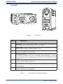
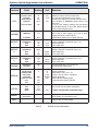
1
Optisure Optical Hygrometer User’s Manual Dewpoint Pressure Water Content °C °C dp Status Duration Process Fault Sensor 0.1 MEASURE 00:14:22 ON OFF CONTROL Dewpoint Dewpoint °C Pressure Pressure Bara Water Content Content Water gm3 °C °C dp 0.1 dp 0.1 Status Status MEASURE MEASURE Duration Duration 00:14:22 00:14:22 Process Process ON ON Fault Fault OFF OFF Sensor Sensor CONTROL CONTROL Kahn Instruments, Inc. 2015 This document is the property of Kahn Instruments and may not, either in part or whole, be copied or otherwise reproduced, communicated in any way to third parties nor stored in any data processing system, without the written authority of Kahn Instruments, Inc. Dewpoint Pressure Water Content °C °C dp Status Duration Process Fault Sensor 0.1 MEASURE 00:14:22 ON OFF CONTROL Optisure Rack-Mount Version For Kahn Instruments' contact information please go to www.kahn.com Optisure Optical Hygrometer User’s Manual Contents Safety............................................................................................................................... viii Electrical Safety.......................................................................................................... viii Pressure Safety........................................................................................................... viii Toxic Materials............................................................................................................ viii Repair and Maintenance.............................................................................................. viii Calibration.................................................................................................................. viii Safety Conformity....................................................................................................... viii Abbreviations.......................................................................................................................ix Warnings.............................................................................................................................ix 1 2 3 INTRODUCTION.................................................................................................1 1.1 Operating Principle.............................................................................................. 2 INSTALLATION...................................................................................................4 2.1 Safety................................................................................................................. 4 2.2 Unpacking the Instrument.................................................................................... 4 2.3 Operating Requirements...................................................................................... 6 2.3.1 Environmental Requirements.......................................................................... 6 2.3.2 Electrical Requirements.................................................................................. 6 2.4 Exterior Layout.................................................................................................... 7 2.5 Rear Panel Connections (All Versions)................................................................. 10 2.5.1 Power Supply Input...................................................................................... 10 2.5.2 Analog Output Connections........................................................................... 11 2.5.3 Alarm Output Connections............................................................................ 12 2.5.4 Remote PRT Probe (Optional) ...................................................................... 14 2.5.5 4-Wire PRT Output....................................................................................... 15 2.5.6 USB Communications Port Connector............................................................. 15 2.5.7 Connection of Gas Supplies........................................................................... 16 2.5.8 Conversion of a Horizontal Version to Rack Mount ......................................... 18 2.5.9 Fitting Rack Mounted Version into Rack......................................................... 19 2.5.10 Fitting the Safety Strap................................................................................. 20 OPERATION.....................................................................................................21 3.1 3.2 3.2.1 3.2.2 3.2.3 3.3 3.3.1 3.3.2 3.4 3.4.1 3.5 3.6 3.6.1 3.6.2 3.6.3 3.6.4 3.7 3.8 3.9 3.10 General Operational Information......................................................................... 21 Function Keys.................................................................................................... 22 Up and Down Arrow Keys ........................................................................... 22 Left and Right Arrow Keys............................................................................ 22 Enter or Select Key....................................................................................... 22 Instrument Display............................................................................................ 23 Operational Data Display.............................................................................. 24 Operational Status Display............................................................................ 25 Menu Structure................................................................................................. 26 Operating Cycle........................................................................................... 28 First Time Operation - Operate Mode.................................................................. 29 Operating Functions.......................................................................................... 30 DCC - Dynamic Calibration Control................................................................ 30 MAXCOOL Function...................................................................................... 32 STANDBY Function....................................................................................... 33 SETUP Menu................................................................................................ 34 Pressure Measurements..................................................................................... 36 Logging Function............................................................................................... 36 FAST - Frost Assurance Technology..................................................................... 37 External PRT..................................................................................................... 38 Kahn Instruments 3 Optisure Optical Hygrometer User’s Manual 4 5 6 7 8 APPLICATION SOFTWARE.................................................................................39 4.1 Installation........................................................................................................ 39 4.2 Establishing Communications............................................................................. 39 4.2.1 USB Communication..................................................................................... 40 4.3 Data Acquisition or Edit Variables Mode............................................................... 41 4.3.1 Data Acquisition........................................................................................... 42 4.3.2 Variable Edit................................................................................................ 44 MAINTENANCE.................................................................................................46 5.1 5.2 5.3 5.4 5.4.1 Safety............................................................................................................... 46 Fuse Replacement ............................................................................................ 46 Fan Filter Cleaning............................................................................................. 47 Sensor Mirror Cleaning....................................................................................... 48 Fitting the Microscope (Optional)................................................................... 49 GOOD MEASUREMENT PRACTICE......................................................................50 6.1 Sampling Hints.................................................................................................. 51 CALIBRATION...................................................................................................54 7.1 Traceability....................................................................................................... 54 PREPARATION FOR SHIPPING...........................................................................55 Tables Table Table Table Table Table Table Table Table Table Table Table Table Table Table Table Table Table Table Table Table Table 1 2 3 4 5 6 7 8 9 10 11 12 13 14 15 16 17 18 19 20 21 Front Panel Controls and Indicators...............................................................8 Rear Panel Controls and Indicators................................................................9 Default Set-Up Parameters.......................................................................... 35 Data Acquisition Control Description............................................................ 42 Graph Control Description........................................................................... 43 Status Bar Description................................................................................ 43 Modbus Holding Register Map..................................................................... 67 Register Configuration A............................................................................. 68 Register Configuration B1............................................................................ 68 Register Configuration B2............................................................................ 68 Register Configuration D Status Word.......................................................... 69 Register Configuration E Units..................................................................... 69 Register Configuration F Display Setting A.................................................... 69 Register Configuration F Display Setting B.................................................... 70 Register Configuration H............................................................................. 70 Register Configuration J.............................................................................. 70 Register Configuration K............................................................................. 70 Register Configuration L.............................................................................. 71 Register Configuration M............................................................................. 71 Register Configuration N............................................................................. 71 Register Configuration P.............................................................................. 73 4 Issue 9.2, January 2014 Optisure Optical Hygrometer User’s Manual Figures Figure Figure Figure Figure Figure Figure Figure Figure Figure Figure Figure Figure Figure Figure Figure Figure Figure Figure Figure Figure Figure Figure Figure Figure Figure Figure Figure Figure Figure Figure Figure Figure Figure Figure Figure Figure Figure Figure Figure Figure Figure Figure Figure Figure Figure Figure Figure Figure 1 2 3 4 5 6 7 8 9 10 11 12 13 14 15 16 17 18 19 20 21 22 23 24 25 26 27 28 29 30 31 32 33 34 35 36 37 38 39 40 41 42 43 44 45 46 47 48 Optisure - Horizontal Model..........................................................................1 Operating Principle......................................................................................3 Optisure Optical Hygrometer Packing............................................................4 Optisure Accessories....................................................................................5 Front Panel.................................................................................................8 Rear Panel..................................................................................................9 Power Supply Input...................................................................................10 Analog Output Connectors.........................................................................11 Alarm Output Connectors...........................................................................13 Remote PRT Connection.............................................................................14 Internal PRT Output..................................................................................15 USB Port Connection..................................................................................15 Gas Connections........................................................................................16 Conversion of Horizontal to Rack Mount......................................................18 Rack Fixing Method...................................................................................19 Removing the Blanking Plug.......................................................................20 Fitting or Removing the Safety Strap...........................................................20 Function Keys............................................................................................22 Typical Front Page Display..........................................................................23 Set-up Display...........................................................................................24 Main Menu................................................................................................26 Menu Structure.........................................................................................27 Typical Operating Cycle..............................................................................28 Main Display.............................................................................................29 Main Menu Display....................................................................................30 DCC ON/OFF.............................................................................................31 Switching MAXCOOL and MEASURE Mode...................................................32 Switching STANDBY and OPERATE Mode.....................................................33 Set-up Menu Selection...............................................................................34 DCC Sub-Menu Selection............................................................................34 Set Parameter Value..................................................................................34 Communications Setup Screen...................................................................39 Windows Device Manager Screen...............................................................40 Options Screen..........................................................................................41 Data Acquisition Screen.............................................................................42 Optisure Series Variables Editor Screen.......................................................45 Power Supply Fuse Replacement................................................................46 Remove and Replace Fan Filter...................................................................47 Mirror and Optics Cleaning.........................................................................48 Fitting the Microscope................................................................................49 Typical Calibration Certificate......................................................................54 Instrument Packing Details.........................................................................55 Select Format............................................................................................60 Set Format Properties................................................................................60 Format Disc..............................................................................................60 Modbus Connection...................................................................................65 Device Manager Screen.............................................................................76 Communications Window...........................................................................77 Kahn Instruments 5 Optisure Optical Hygrometer User’s Manual Appendices Appendix A Appendix B Appendix C Appendix D Appendix E Appendix F Technical Specifications............................................................................... 57 Formatting SD cards .................................................................................. 60 Calculations............................................................................................... 62 C.1 Water Content.............................................................................. 62 C.2 Temperature - Dew Point ............................................................ 62 C.3 °C to °F Calculation ..................................................................... 62 C.4 % RH Calculation......................................................................... 62 C.5 Conversion of bara to psia and kPa ............................................... 63 Modbus RTU Communications..................................................................... 65 D.1 Introduction ................................................................................ 65 D.2 Basic Modbus Operation ............................................................... 65 D.3 Modbus RTU Connections and Protocol........................................... 66 D.4 Register Map ............................................................................... 66 Installation of the Application Software........................................................ 75 EC Declaration of Conformity....................................................................... 79 6 Issue 9.2, January 2014 Optisure Optical Hygrometer User’s Manual Safety The manufacturer has designed this equipment to be safe when operated using the procedures detailed in this manual. The user must not use this equipment for any other purpose than that stated. Do not apply values greater than the maximum value stated. This manual contains operating and safety instructions, which must be followed to insure the safe operation and to maintain the equipment in a safe condition. The safety instructions are either warnings or cautions issued to protect the user and the equipment from injury or damage. Use qualified personnel and good engineering practice for all procedures in this manual. Electrical Safety The instrument is designed to be completely safe when used with options and accessories supplied by the manufacturer for use with the instrument. The input power supply voltage limits are 85 to 264 V AC, 47/63 Hz. Refer to Appendix A - Technical Specifications. Pressure Safety ! Before pressurizing, the user must insure through appropriate protective measures that the system or the device will not be overpressurized. When working with the instrument and pressurized gases safety glasses should be worn. DO NOT permit pressures greater than the safe working pressure to be applied to the instrument. The specified maximum safe working pressure is 14.5 psig (1 barg) for the low pressure version, or 250 psig (17 barg) for the high pressure version. The safety strap MUST be used when operating at pressures above 14.5 psig (1 barg), refer to Section 2.5.10. This instrument is not designed to accept gas pressures higher than the specified maximum working pressure. Application of gas pressures higher than the specified maximum will result in potential damage and may render the instrument unsafe and in a condition of incorrect functionality. Only personnel trained in the safe handling of high pressure gases should be allowed to operate this instrument. Refer to Appendix A - Technical Specifications in this manual. Kahn Instruments 7 Optisure Optical Hygrometer User’s Manual Abbreviations The following abbreviations are used in this manual: DCC FAST MAXCOOL AC atm barg bara °C °F COM dp EU g/Kg g/m3 HMI Hz IEC Nl/min lb mA max min mV N/C N/O No ppmV ppmW PRT psig psia RH RTU scfh SD temp USB V Dynamic Contamination Correction Frost Assurance System Technology Maximum Sensor Cooling alternating current pressure unit (atmosphere) pressure unit (=100 kP or 0.987 atm) gauge pressure unit (absolute) degrees Celsius degrees Fahrenheit common dew point European Union grams per kilogram grams per cubic meter Human Machine Interface Hertz International Electrotechnical Commission normal liters per minute pound milliampere maximum minute(s) millivolt(s) normally closed normally open number parts per million (by volume) parts per million (by weight) Platinum resistance thermometer (typically type Pt100) pound(s) per square inch (gauge) pound(s) per square inch (absolute) relative humidity Remote Terminal Unit standard cubic feet per hour storage device card (memory card for storing datalog files) temperature Universal Serial Bus Volts Warnings The following general warnings listed below are applicable to this instrument. They are repeated in the text in the appropriate locations. ! DANGER Electric Shock Risk Where this hazard warning symbol appears in the following sections, it is used to indicate areas where potentially hazardous operations need to be carried out. Where this symbol appears in the following sections it is used to indicate areas of potential risk of electric shock. 8 Issue 9.2, January 2014 Optisure Optical Hygrometer User’s Manual Page intentionally left blank Kahn Instruments 9 Optisure Optical Hygrometer User’s Manual 1 INTRODUCTION INTRODUCTION The Optisure Optical Hygrometer is a high precision instrument used for the measurement of moisture content in air and other gases. Relative humidity and other calculated parameters based on dew point, pressure and temperature of the sample gas can also be displayed. The Optisure Optical Hygrometer is capable of measuring dew points as low as -60°C (-76°F); it can measure dew points up to (but not including) the point of condensation (maximum +40°C (+104°F)). Four models of the Optisure Optical Hygrometer instrument are available: • • Vertical model • Low Pressure (14.5 psig (1 barg) max) • High Pressure (250 psig (17 barg) max) Horizontal model • Low Pressure (14.5 psig (1 barg) max) • High Pressure (250 psig (17 barg) max) A rack mounted configuration is available which is a derivative of the horizontal model. Any horizontal model may be converted to a rack mounted version by means of a special rack mounting kit, (refer to Section 2.5.8). Dewpoint Pressure Water Content Figure 1 °C °C dp Status Duration Process Fault Sensor 0.1 MEASURE 00:14:22 ON OFF CONTROL Optisure - Horizontal Model Kahn Instruments 1 INTRODUCTION 1.1 Optisure Optical Hygrometer User’s Manual Operating Principle The system operates on the chilled mirror principle, whereby a gas sample is passed into the sensor housing and flows over the surface of the chilled mirror contained within. At a temperature dependent upon the moisture content in the gas, and the operating pressure, the moisture in the gas condenses out on the surface of the mirror. An optical system is used to detect the point at which this occurs, and this information is used to control the mirror temperature and maintain a constant thickness of the condensation layer on the mirror surface. A light emitting diode (1) (see Figure 2) provides a light beam of constant intensity which is focused by a lens system (2) to become the incident beam on the mirror surface (3), flooding it with a pool of light. Before the light beam reaches the mirror (3), a beam splitter (4) directs part of the beam via a lens system (5) onto a sensor (6) which monitors the intensity of the LED light and provides a feedback loop to keep this at a constant level. Two sensors (7 and 8) monitor the light level reflected by the mirror. One of these sensors (7) measures the light level due to the reflected incident beam and the other (8) measures the degree of light scatter due to the formation of water/ice on the mirror surface. Each sensor has its own optical lens system (9) and (10) to concentrate the reflected light onto the sensor. The output from each of these sensors is compared and then used to control the drive to a Peltier heat pump (11). Dependant on the result of this comparison, the control system will cause the heat pump (11) to either heat or cool the mirror (3) in order to maintain the desired condensation film thickness on the mirror surface. At an equilibrium point, where the evaporation rate and condensation rate at the surface of the mirror are equal, the mirror temperature, read by a Pt100 platinum resistance thermometer (12) embedded in the mirror, represents the dew point. 2 Issue 9.2, January 2014 Optisure Optical Hygrometer User’s Manual 4 9 INTRODUCTION 7 1 5 6 2 8 3 10 12 11 Figure 2 Operating Principle Kahn Instruments 3 Optisure Optical Hygrometer User’s Manual INSTALLATION 2 INSTALLATION 2.1 Safety ! 2.2 It is essential that the installation of the electrical and gas supplies to this instrument be undertaken by competent personnel. Unpacking the Instrument Both the horizontal and vertical models are packed in a similar manner. Figure 3 shows the unpacking method. NOTE: The free-standing, horizontal version may be converted to a rack mounted instrument by means of an optional rack mounting kit (refer to Section 2.5.8). 1 2 3 4 5 Figure 3 Optisure Optical Hygrometer Packing 4 Issue 9.2, January 2014 Optisure Optical Hygrometer User’s Manual INSTALLATION Open the box and unpack carefully as follows (see Figure 3) : 1. Remove the accessories box (4). 2. Lift out the instrument (2) together with its end packing pieces (1) and (3). 3. Remove the end packing pieces (1) and (3) set the instrument down at the site of installation. 4. Save all the packing materials for the purpose of returning the instrument for re-calibration or any warranty claims. The accessories box should contain the following items (refer to Figure 4): 1. Traceable calibration certificate 2. SD memory storage card 3. Optics cleaning kit 4. Microscope (optional) 5. USB communications cable 6. Pt100 temperature probe (optional) 7. IEC power cable 8. Application software CD 9. User’s manual 10. Safety strap (supplied with High Pressure versions) If there are any shortages, please notify Kahn Instruments immediately (see www.kahn.com for contact information). Figure 4 Optisure Accessories Kahn Instruments 5 Optisure Optical Hygrometer User’s Manual INSTALLATION 2.3 Operating Requirements 2.3.1 Environmental Requirements The horizontal and vertical Optisure instruments should be placed on a firm and level surface in a standard laboratory environment. Recommended ambient temperature +68 to +77°F (+20 to +25°C) although the instrument will operate, within specification, at elevated ambient temperatures of up to +122°F (+50°C), providing the cooling vents are kept clear and unrestricted. It is essential however that this upper temperature limit (+122°F / +50°C) is not exceeded. A free flow of air around the instrument is required at all times. Rack mounted versions are suitable for mounting in standard 19" racks. The siting of these racks should be in a dry, dust free environment at a recommended ambient temperature of +68 to +77°F (+20 to +25°C). ! 2.3.2 For rack mounted instruments, forced air cooling of the rack should be considered if operating at high ambient temperatures. Electrical Requirements All versions of the instrument require the following electrical supply: • 85 to 264 V AC, 47/63 Hz, 100 VA max • Alarm outputs for all instrument types comprise two sets of changeover relay contacts, one set for a PROCESS alarm and one set for an INSTRUMENT FAULT. Both sets of contacts are rated at 24 V, 1A. NOTE: THIS RATING MUST NOT BE EXCEEDED. 6 Issue 9.2, January 2014 Optisure Optical Hygrometer User’s Manual 2.4 INSTALLATION Exterior Layout The controls and indicators relating to the operator interface are located on the front panel, along with the gas inlet and outlet. The external PRT connection, power IEC socket, analog output connector, remote temperature probe connector, alarm relay connector, and the USB socket are located on the rear panel. Figures 5 and 6 show the layout of these controls for both the rack mount/horizontal and vertical versions of the instrument. Tables 1 and 2 detail the controls and indicators and the function key operations. ! ! The microscope should not be used when the system is operating at pressures above 14.5 psig (1 barg). The safety strap should be installed when the the system is operating at pressures above 14.5 psig (1 barg) (see Section 2.5.10). Kahn Instruments 7 Optisure Optical Hygrometer User’s Manual INSTALLATION Front Panel 1a 2 Dewpoint °C Pressure Water Content °C dp Status Duration Process Fault Sensor 0.1 MEASURE 00:14:22 ON OFF CONTROL Dewpoint Dewpoint 3 °C Pressure Bara Water Content gm3 °C °C 0.1 dp 0.1 Status MEASURE MEASURE Duration 00:14:22 Duration 00:14:22 Process Process ON ON Fault OFF Fault OFF Sensor Sensor CONTROL CONTROL 4 6 5 4 3 2 1 5 Figure 5 Item 6 Front Panel Description 1 Microscope - For viewing mirror surface. The microscope is removable and must not be used at pressures above 14.5 psig (1 barg). 1a Safety Strap - Must be equipped when the system is operating at pressures above 14.5 psig (1 barg). Refer to Section 2.5.10. 2 Exterior housing of the sensor - See Section 5.4 for instructions on how to open the housing and clean the mirror. 3 Instrument display - Partitioned to show three main panes each of which can be configured to display one of the ten available output parameters. A second area of the display shows a stability graph, and other process related data. Refer to Section 3.3. 4 Function keys - Used to control the instrument functions and navigate through the menu system. Refer to Section 2.2. 5 Gas input port - Usually slightly above atmospheric pressure in order to maintain flow rate over the mirror, but can be at elevated pressure depending upon application. 6 Gas output port - Usually vented to atmosphere but can be at elevated pressures depending upon application. Table 1 Front Panel Controls and Indicators 8 Issue 9.2, January 2014 Optisure Optical Hygrometer User’s Manual INSTALLATION Rear Panel 11 12 13 14 11 12 13 14 10 9 10 9 8 7 8 7 Figure 6 Item 7 Rear Panel Description Analog output connector - Three, 2-wire output channels, CH1, CH2 and CH3, each of which may be configured to give either a 0-20 mA or a 4-20 mA current loop output or a 0 to 1000 mV voltage signal representing any one of the measured or calculated output parameters selected. Spans for each signal output are separately configurable. Refer to Section 2.5.2. 8 9 Remote temperature probe (optional) - 6-Pin Lemo socket for connection of remote Pt100 temperature probe. Alarms - Process and Fault alarm outputs. Each alarm has one set of potential free, changeover, relay contacts, common (COM), normally closed (N/C) and normally open (N/O). The Process alarm can be configured to operate at a specified level on any of the measured or calculated parameters. Refer to Section 2.5.3. 10 USB communications port - Used for connection to an external computer system for running application software (optional). 11-13 IEC Power supply input socket and power ON/OFF switch - Universal power input 85 to 264 V AC, 47/63 Hz / Fuse - 2.5 A, Anti-Surge, Glass, 20mm x 5mm (12) / Features integrated power ON/OFF switch (13). 14 4-wire PRT bridge output - Banana sockets for external 4-wire measurement of the internal PRT. Active only when PRT set to External from Display options, and instrument is in the MEASURE phase. In this mode the dew-point display is set to read zero, DCC is set to OFF and manual DCC is also disabled. Table 2 Rear Panel Controls and Indicators Kahn Instruments 9 Optisure Optical Hygrometer User’s Manual INSTALLATION 2.5 Rear Panel Connections (All Versions) ! These tasks should be undertaken only by competent personnel. All the connections to the rear panel are electrical connections. DANGER Electric Shock Risk Exercise due caution, particularly when connecting to external alarm circuits which could be at high potential. Connections to the rear panel of the instrument are explained in the following sections. 2.5.1 Power Supply Input The AC power supply is a push fit into the power input socket as shown in Figure 7. The method of connection is as follows: 1. Insure that both ends of the power cable are potential free i.e. not connected to an AC power supply. 1 2. Check that the ON/OFF switch (1) on the power supply connector is switched to OFF. 3. Push the IEC connector (2) firmly into the power input socket (3). 4. Connect the free end of the power cable to a suitable AC power supply source (voltage range 85 to 264 V AC, 47/63 Hz) and switch on the AC supply. The instrument may then be switched on, as required, using the ON/OFF switch. 3 Figure 7 2 Power Supply Input 10 Issue 9.2, January 2014 Optisure Optical Hygrometer User’s Manual 2.5.2 INSTALLATION Analog Output Connections The three analog outputs can be configured to represent any of the directly measured or calculated output parameters. They are provided as 2-wire signals from a 6-way connector located on the rear panel of the instrument. Each of these outputs can be set up as either a current loop signal (4-20 mA or 0-20 mA) or alternatively, as a 0-1 V voltage signal. The configuration of these outputs, i.e. parameter represented, output type (current loop or voltage) and upper/lower span levels are set up via the SETUP Menu Screen (refer to Section 3.6.4). These signals may be used to control external systems. During a DCC cycle, and for the hold period following a DCC cycle, they are held at the level that they were at immediately prior to the start of the cycle. When the dew-point measurement is stable, or if the maximum hold period has expired, they are released and will track the selected parameter throughout the measurement cycle. The default settings of these analog outputs are: Channel 1: Dew point, -60 to +40ºC Channel 2: ppmV, 0 to 3000 Channel 3: Flow, 0 to 1000 ml/min NOTE: The analog outputs are only active during the MEASURE phase. They will, therefore, be off after switch-on and remain off until the system enters the MEASURE phase. The three analog output ports connections are made via a single, 6-way, push fit connector block as shown in Figure 8. All outputs are 2-wire, positive-going signals referenced to a common 0 V line. To differentiate between the outputs it is recommended that a black lead be used for each of the COM (common) lines and a separate color for each of the positive lines. Figure 8 Analog Output Connectors Kahn Instruments 11 INSTALLATION Optisure Optical Hygrometer User’s Manual For each output: 2.5.3 1. Remove the terminal block equipped into the analog output socket. 2. Strip back the wire for the common (black) connection to the CH1 output, exposing approximately 6mm (0.25"). Insert the wire into the COM1 terminal way and screw into the block. Do not overtighten the screw. 3. Strip back the wire for the signal (e.g. red) connection to the OP1 output, exposing approximately 6mm (0.25"). Insert the wire into the OP1 terminal way and screw into the block. Do not overtighten the screw. 4. Repeat operations 1 and 2 for the other analog outputs, selecting a different color for the OP2 and OP3 outputs. 5. Locate the terminal block over the connector labelled ANALOG OUTPUTS and push the terminal block firmly into the connector. Alarm Output Connections Two alarm outputs are provided from a terminal block (Item 9, Figure 6), located on the rear panel of the instrument as two pairs of potential free, change-over relay contacts. These are designated as a PROCESS alarm and a FAULT alarm. Under the SETUP menu, (refer to Section 3.6.4), the PROCESS alarm can be configured to represent any one of the measured or calculated parameters and set-up to operate when a pre-set parameter threshold level is exceeded. By default, the PROCESS alarm is set to monitor the dew-point parameter. The FAULT alarm is a non-configurable alarm which continuously monitors the degree of contamination of the chilled mirror. During normal operational conditions, this alarm will be off. If the optics or the mirror contamination exceeds 100% of the film thickness, or if a fault exists on the Pt100, the alarm is triggered, and the relay contacts will change state. This fault is also reported to the status area of the display. The two alarm output ports are connected to the instrument via a single 6-way, push-fit connector block as shown in Figure 9. Each output comprises a 3-wire set of potential free, change-over relay contacts. Each contact set is labelled COM (common 0 V), N/O (normally open with respect to COM) and N/C (normally closed with respect to COM). To differentiate between the alarm output channels, it is recommended that a black lead be used for each of the COM (common) lines and a separate color for each of the N/O and N/C lines. 12 Issue 9.2, January 2014 Optisure Optical Hygrometer User’s Manual DANGER Electric Shock Risk INSTALLATION WARNING: Alarm leads MUST be potential free when wiring to connector block. Figure 9 Alarm Output Connectors For each output: 1. Strip back the wire for the common (black) connection to the COM connector way for the FAULT alarm contact set, exposing approximately 6mm (0.25") wire and clamp into the screw block COM terminal way. Do not overtighten the screw. 2. Strip back the wire for the N/O (e.g. green) connection to the N/O connector way for the FAULT alarm contact set, exposing approximately 6mm (0.25") wire and clamp into the screw block N/O terminal way. Do not overtighten the screw. 3. Strip back the wire for the N/C (e.g. blue) connection to the N/C connector way for the FAULT alarm contact set, exposing approximately 6mm (0.25") wire and clamp into the screw block N/C terminal way. Do not overtighten the screw. 4. Repeat operations 1 to 3 for the PROCESS alarm contact set, using appropriate colored wires. 5. Locate the terminal block over the connector labelled ALARMS and push the terminal block firmly into the connector. Kahn Instruments 13 Optisure Optical Hygrometer User’s Manual INSTALLATION 2.5.4 Remote PRT Probe (Optional) 1. Rotate the body of the PRT probe connector until it locates in the socket labeled REMOTE TEMPERATURE (see Figure 10). 2. Push the connector into the socket until it locks. Do not attempt to force it into the socket. If it will not fit in, rotate it until the key locks and it pushes in easily. 3. To remove the connector, slide the connector’s body collar (1) back along its axis, away from the instrument to release the lock and then gently pull the connector body out of the socket. Do not attempt to pull it out with the cable - make sure that the collar is first released. 1 Figure 10 Remote PRT Connection 14 Issue 9.2, January 2014 Optisure Optical Hygrometer User’s Manual 2.5.5 INSTALLATION 4-Wire PRT Output These four terminal binding posts (Items 1 to 4, Figure 11), are provided for calibration and external monitoring purposes. Two pairs of lines are provided, two drive and two sense lines. One black (low) and one red (high) for the drive lines, and one black (low) and one red (high) for the sense lines. Connections to these terminal posts can be made either via 4mm plugs pushed into the ends of the terminal posts or, alternatively, as shown, wires (5) connected round the posts and clamped down by screw action. To set-up the system for PRT output refer to Section 3.10. 2.5.6 1 2 3 Figure 11 4 5 Internal PRT Output USB Communications Port Connector The instrument features a USB port for communication with the Application Software. The appropriate cable will be supplied with the instrument. 1. Check the orientation of the connector and gently push it into the socket labelled USB (see Figure 12). 2. To remove the connector, pull it out of the socket by holding the connector body. Do not attempt to remove it from the socket by pulling on the cable. Figure 12 USB Port Connection Kahn Instruments 15 Optisure Optical Hygrometer User’s Manual INSTALLATION 2.5.7 Connection of Gas Supplies ! POSSIBLE INJURY! The tubing, valves and other apparatus attached to this instrument must be adequate for the maximum pressure which will be applied, otherwise physical injury to the operator or bystander is possible. ! Before connection or disconnection of the instrument to and from the gas line it is essential to vent the system to atmospheric pressure, otherwise severe injury could result. The safety strap should be equipped when the the system is operating at pressures above 14.5 psig (1 barg) (see Section 2.5.10). ! Sample gas connections are made via the GAS IN port (7) and the GAS OUT port (8) located on the front panel of all the models. As the method of connection is the same for all types, only the horizontal version has been illustrated (see Figure 13): 7 Dewpoint °C Pressure °C dp Status Duration Process Fault Sensor Water Content 0.1 MEASURE 00:14:22 ON OFF CONTROL 8 1 2 6 5 4 3 1, 2 6 5 4 3 2 1 Figure 13 Gas Connections 16 Issue 9.2, January 2014 Optisure Optical Hygrometer User’s Manual INSTALLATION Both the input and output gas connections are ¼” NPT Swagelock® couplings. The gas input connection must always be made via ¼” stainless steel piping. The gas output connection for most applications can just be exhausted to atmosphere via 305mm (12") of PTFE tubing (1). The method of connection to the GAS IN port (7) is as follows. NOTE: The following description relates to ¼" tube fixings. The instrument ports are both ¼" NPT female fittings. Two sets of tube fittings (adaptor (6), front (5) and back (4) ferrules and locking nut (3) are supplied in the accessories box. EU and CN versions are supplied with 6mm fittings and NA fittings are ¼". Other fittings (3mm and ⅛") are also available to order. 1. Cut ¼" stainless steel tubing (2) to the correct length and, if necessary, bend to shape to suit the location of the instrument. NOTE: To facilitate ease of connection to the port, at least 3" (75mm) of the tubing coming out of the GAS IN port should be straight. 2. Clean off any burrs or metal shavings adhering to the tubing. 3. Screw the ¼” NPT Swagelok adaptor (6) into the ¼” NPT inlet port of the instrument and tighten. Wrap the ¼” NPT male thread in one layer of PTFE tape to facilitate a gas tight seal. CAUTION: Do not overtighten. 4. Pass the tubing (2) through the locking nut (3). NOTE: Threads towards the gas port. 5. Fit the back ferrule (4) over the tubing (2) with the bevelled end facing the back of the front ferrule (5). 6. Place the front ferrule (5) over the tubing (2), bevelled end towards the adaptor (6). 7. Push the tubing as far as it will go into the fitting and tighten up the locking nut (3) finger tight. 8. Hold the adaptor (6) flats with a wrench and tighten up the locking nut (3). This action compresses the front ferrule (5) and back ferrule (4) onto the tubing to form a gas tight seal. CAUTION: Do not overtighten as this could cause the ferrules to crack and destroy the integrity of the seal. 9. Connect up the GAS OUT port (8) in a similar manner to that described in operations 1 - 8 above using PTFE tubing (1) in place of stainless steel (2). Kahn Instruments 17 Optisure Optical Hygrometer User’s Manual INSTALLATION 2.5.8 Conversion of a Horizontal Version to Rack Mount To convert a Optisure horizontal version to a rack mounted version a rack mounting kit (Optional - Part No. S8K-PKI) is required. This conversion pack comprises two steel wings (3) and eight cap screws (1), each wing bolting to the side of the instrument with four screws as shown in Figure 14. 1 2 3 3 Figure 14 2 1 Conversion of Horizontal to Rack Mount 1. Turn the unit on its left hand end and line up the fixing holes on the right hand side of the instrument with the corresponding holes in the right hand wing (flange facing outwards). 2. Insert the four cap screws (1) and washers (2) through the wing (3) and tighten finger tight. 3. Insure that the front flange (3) is square to the front of the instrument and tighten the cap screws 4. Turn the unit on its right hand end and repeat operations 1 - 3. To remove the rack support wings remove the unit from the rack (if necessary) and follow the directions above, in reverse. 18 Issue 9.2, January 2014 Optisure Optical Hygrometer User’s Manual 2.5.9 INSTALLATION Fitting Rack Mounted Version into Rack Figure 15 illustrates the method for fitting a rack mount instrument into a standard 19” rack. To fit the unit proceed as follows: 4 3 2 1 4 3 2 1 Figure 15 Rack Mounting Method 1. Remove the connector blocks from the alarm and analog output sockets. 2. If necessary, remove any covers from the rack cabinet to gain access to the rear and side. 3. Connect up the analog and alarm output connector blocks to the internal rack wiring (refer to Section 2.5), ensuring that there is sufficient free cable to permit withdrawal of the instrument from the rack. 4. Slide the instrument into the rack and support its weight while the four fixing screws are inserted. 5. Insure that the front panel of the instrument is flush and square with the front of the rack and tighten the fixing screws. 6. Insert the analog and alarm connectors into their respective sockets on the rear of the instrument (refer to Section 2.5) and connect the external PRT probe and USB communications cable and connector as appropriate. 7. Connect the power supply cable and switch the ON/OFF switch to ON. 8. Refit any covers to the rack as necessary. To remove from the rack follow the directions above, in reverse. Kahn Instruments 19 Optisure Optical Hygrometer User’s Manual INSTALLATION 2.5.10 Fitting the Safety Strap WARNING A safety strap must be equipped when the instrument is operating at pressures higher than 14.5 psig (1 barg) ! The purpose of the safety strap is to secure both over-center locking bars in position to prevent them from being unexpectedly disengaged from the sensor housing. If the strap is not installed, the sensor housing could spring open causing damage to the instrument. On both high pressure models, the safety strap is installed as follows (refer to Figures 16 and 17): 1. Insure that the sensor chamber is at atmospheric pressure before pulling out the blanking plug (1) from the sensor housing. 2. Insure that both over-center clamps (2) are vertical (locked) and locate the two eyes (3) in the safety strap, one over each locking bar, and push the plug (4) fully into the microscope fixing hole. 3. Lock the safety bar into position by rotating the locking screw (5) clockwise. Safety strap removal 1. Insure that the sensor chamber is at atmospheric pressure. 2. Rotate the locking screw (5) counter clockwise and lift off the safety strap. 1 1 Figure 16 Removing the Blanking Plug 2 5 3 Figure 17 4 5 Fitting or Removing the Safety Strap 20 Issue 9.2, January 2014 Optisure Optical Hygrometer User’s Manual 3 OPERATION OPERATION As supplied, the Optisure is ready for operation and has been set-up with a set of default parameters. This section describes both the general operation of the instrument and the method of setting it up and changing the default parameters should this become necessary. Before operating the instrument read this section, which describes the operation of the instrument’s controls and explains the display functions in detail. Prior to operation the instrument must have been connected to a sample gas supply as detailed in Section 2.5.7, the correct electrical power supply and the relevant analog and alarm outputs connected to external systems as described in Section 2. On delivery the instrument will have been set-up with a standard set of default parameters defining the operation of the instrument. These parameters can be changed as required by means of the SETUP Menu (refer to Section 3.6.4). 3.1 General Operational Information Operation of the Optisure hygrometer is completely automatic and, once set-up for a measurement cycle, requires little or no operator intervention. While the instrument can physically operate in a flowing gas stream of between 0.6 and 2.1 scfh, (0.3 and 1 Nl/min), Kahn Instruments recommends operating at 1.06 scfh (0.5 Nl/min) which is the flow-rate used during calibration. Operating at an alternative rate could impact the instrument’s response time. For all applications, the sample gas is taken into the instrument via the GAS IN port located on the front panel, from where it passes into a sample chamber. The gas flow rate is then measured on the exhaust side of the sample chamber, prior to being exhausted from the instrument via the GAS OUT port. The sample gas flow rate is not controlled within the instrument. If necessary this must be controlled outside the instrument, typically by means of a needle valve located at the input. Within the sample chamber, the gas is passed over a Peltier chilled, gold-plated mirror. The instrument’s internal control system maintains the drive to the Peltier heat pump to insure, by controlling the mirror temperature, that a level of condensate is maintained on the mirror surface. The temperature of the mirror is then measured as the dew point. After passing over the mirror, the sample gas is then typically exhausted to atmosphere via the GAS OUT port. Using this configuration, dew-point measurements are taken at atmospheric pressure. The sampling chamber is available in two different configurations; low pressure and high pressure. The low pressure version is designed to operate up to 14.5 psig (1 barg) max and the high pressure version up to 250 psig (17 barg) max. When operating in high pressure applications, a relevant gas sample line, representative of the product, would be taken and fed into the instrument. The output port would, in these applications, be connected to a suitable high pressure exhaust line. The gas flow would also need to be regulated externally on the output port of the instrument to maintain it within the instrument’s operational limits. The Optisure is suitable for the measurement of moisture content in a wide variety of clean, non-corrosive gases. It will not contaminate high purity gases and is safe for use in critical semi-conductor and fiber optic manufacturing applications. Kahn Instruments 21 OPERATION Dewpoint 3.2 1 °C °C 0 Function Keys Pressure Optisure Optical Hygrometer User’s Manual 1 0 MIN 1 0.1 dp Bara Status MEASURE Duration 00:14:22 Process ON 3 gm OFF Fault CONTROL Sensorbelow keys, located the Water Content 10.32 The function display on all models, are used to select operations from the MAIN menu level, to enter sub-menu levels and to select and enter parameter variables within those menu levels. Figure 18 1 Function Keys °C The SD card reader, used for 1 data storage 0 0 MIN Pressure data logging operations, is located during 0.1 dp below the functionBara keys. Status MEASURE Water Content 10.32 3.2.1 gm 3 Duration Process Fault Sensor 00:14:14 ON OFF CONTROL Up and Down Arrow Keys Dewpoint 11.46 1 °C °C 0 0 MIN 1 The (up) and (down) 0.1 are used to scroll through menus and adjust values. dp keys Water Content 10.32 Left and Right Arrow Keys Dewpoint 3.2.2 MEASURE 00:14:07 ON OFF CONTROL Status Duration Process Fault Sensor Pressure °C Pressure Bara 10.32 gm 3 °C MIN 1 0.1 MEASURE 00:14:22 ON OFF CONTROL dp Status Duration Process Fault Sensor °C 0 Bara 10.32 0 1 1 Water Content 3 °C 0 Water Content Dewpoint gm 1 1 gm 3 0 0 Pressure MIN 0 1 0.1 MEASURE 00:14:22 ON OFF CONTROL dp Status Duration Process 1 Fault °C Sensor MIN dp Status Duration Process Fault Sensor 1 0.1 MEASURE 00:14:14 ON OFF CONTROL The (left) and (right) keys are used to scroll through alternative parameters within 1 Dewpoint 10.32 °C the FRONT page. °C the highlighted panes on Bara Water Content gm 3 11.46 1 0 °C 0 Pressure Bara 0 MIN dp Status Duration Process Fault 1 Sensor °C 1 0.1 MEASURE 00:14:14 ON OFF CONTROL The (left) key Water Content Dewpoint 10.32 11.46 gm 3 °C 0 0 MIN 1 Water Content Status MEASURE 0.1 dp Water Content 3.2.3 10.32 gm 3 0 MIN 1 0.1 dp is also used to step Status MEASURE Duration 00:13:53 Process ON 3 gm OFF Fault Sensor CONTROL back one menu level. 10.32 00:14:07 ON OFF CONTROL Duration Process Fault Sensor 11.46 or Select Key Enter Dewpoint 1 °C °C 0 Water Content Dewpoint 10.32 11.46 Water Content Dewpoint gm 10.32 11.46 3 °C 0 0 gm 3 MIN 0 1 0.1 MEASURE 00:14:07 ON OFF CONTROL dp Status Duration Process Fault 1 Sensor °C MIN dp Status Duration Process Fault Sensor 1 0.1 MEASURE 00:13:53 ON OFF CONTROL 1 °C °C 1 Dewpoint (enter) key is used The to move from one sub menu down to the next level. 0 0 MIN dp Status Duration Process Fault 1 Sensor °C 1 0.1 MEASURE 00:13:53 ON OFF CONTROL 11.46 The (enter) key is also used to select highlighted options in order to change parameter 0.73 10.32 variables within these options. Water Content Dewpoint Flow 10.32 11.46 Flow 0.73 Water Content Dewpoint gm 3 °C 0 l/min gm3 0 MIN dp Status Duration Process Fault Sensor °C 0 1 0.1 MEASURE 00:13:49 ON OFF CONTROL l/min 1 °C Water 11.46Content °C 10.32 0 Flow 0.73 Water Content 10.32 l/min gm3 0 MIN dp Status Duration Process Fault Sensor 1 0.1 MEASURE 00:13:49 ON OFF CONTROL °C gm3 0 MIN dp Status Duration Process Fault Sensor 1 0.1 MEASURE 00:13:49 ON OFF CONTROL 22 Issue 9.2, January 2014 Optisure Optical Hygrometer User’s Manual 3.3 OPERATION Instrument Display For all models of the instrument the display and the associated function keys form the operator interface. FRONT Page Figure 19 shows a typical FRONT page display while the instrument is running in MEASURE Mode. Flow Figure 19 18.49 0.47 l/min Typical Front Page Display The instrument display is divided into two sections. Operational data (measured, or data calculated from measured parameters) is shown in the three horizontal panes on the left hand side. Operational status information is shown in a separate display area on the right hand side. Kahn Instruments 23 Optisure Optical Hygrometer User’s Manual OPERATION 3.3.1 Operational Data Display Each of the three operational data panes can be configured to display one of the following parameters: 1. Dew point 2. Temperature 3. Water content (ppmV) 4. Water content (ppmW) 5. Water content (g/kg) 6. Water content (g/m3) Front page & status display Dewpoint 11.46 2256.42 0.73 Flow 11.46 2256.42 0.73 8. Flow rate Flow 9. % Relative humidity, %RH 10. Temperature difference Pressure 1. gm 3 0 MIN 1 °C 0 2. 3. 0 Water Content gm 3 dp Status Duration Process Fault Sensor Dewpoint Water Content Dewpoint gm 3 °C 10.32 0 MIN Flow Water Content 10.32 0 MIN dp Status Duration Process l/min Fault Sensor ppmv 1 0.1 MEASURE 00:14:14 ON OFF CONTROL 1 °C °C 0 0 MIN 1 0.1 MEASURE 00:14:14 ON OFF CONTROL dp Status Duration Process l/min Fault Sensor 11.46 1 °C Flow 21.42 0.73 °C 0 Temperature °C l/min 0 MIN dp Status Duration Process Fault Sensor 1 0.1 MEASURE 00:13:53 ON OFF CONTROL Accept selected parameter (Temperature) 1 0.1 MEASURE 00:14:07 ON OFF CONTROL dp Status Duration Process Fault Sensor Dewpoint °C gm 3 0 MIN dp Status Duration Process Fault Sensor 1 0.1 MEASURE 00:13:53 ON OFF CONTROL When the required parameter is displayed, press the key. The display will now show an updated FRONT page. 11.46 0.73 0 °C 0 Dewpoint Dewpoint 1 Water Content °C Select new parameter (Temperature) 1 °C 1 0.1 MEASURE 00:14:22 ON OFF CONTROL 1 °C °C 1 0.1 MEASURE 00:14:14 ON OFF CONTROL Use a combination of the (left) and 11.46 (right) keys to scroll through the list of parameters available for display. 10.32 NOTE: A parameter can only be displayed on screen once. If it is already displayed, it is not available for display 11.46 in a second panel on the same screen. 0 4. MIN Use a combination of the (down) and (up) 10.32 keys to highlight the required pane. Bara MIN ppmv Flow 1 0.1 MEASURE 00:14:22 ON OFF CONTROL dp Status Duration Process Fault Sensor Press the (down) key to highlight the top pane. Pressure 11.46 11.46 2256.42 0.73 Water Content 1 Bara Water Content Dewpoint °C To change one of the displayed parameters follow the instructions below (see Figure 20). 10.32 0 dp Status Duration Process Fault Sensor Select pane The parameters displayed are operator selectable and, by default, are set (from the top of the display) to Dew point, Water Content (ppmV) and Flow. 0 l/min Dewpoint Pressure (see also Section 3.7) °C ppmv Select view 7. 1 °C 0 Water Content Water Content Dewpoint 1 °C 1 °C °C 0 l/min gm3 0 MIN dp Status Duration Process Fault Sensor 11.46 1 °C 0 Temperature Flow 21.42 0.73 °C °C l/min 0 MIN dp Status Duration Process Fault Sensor 1 0.1 MEASURE 00:13:53 ON OFF CONTROL New Front Page 1 0.1 MEASURE 00:13:49 ON OFF CONTROL Figure 20 Set-up Display 24 Issue 9.2, January 2014 Optisure Optical Hygrometer User’s Manual 3.3.2 OPERATION Operational Status Display The Status Display is shown on the right hand side of the screen and details the following: 1. Stability graph - shows measured dew point over a user-optional duration. This time variable (Stability Time), is set-up within the DISPLAY option of the SETUP Menu (refer to Section 3.6.4). 2. ∆ dp value - represents the change in dew point over the stability duration as shown on the graph. 3. Status indicator - reports which operational phase the instrument is currently in. This will be either DCC, HOLD, MEASURE or MAXCOOL. 4. Duration indicator - reports back the time (in Hours:Minutes:Seconds format) remaining in the phase currently being displayed in the Status indicator. 5. Process - this two state ON/OFF notification indicates whether a parameter process alarm is either ON or OFF. A process alarm can be set on any parameter and its set-point. The ON/OFF control is set-up via the SETUP Menu (refer to Section 3.6.4). 6. Fault - used to monitor the optical system and the degree of mirror contamination. During normal operation, when there are no fault conditions, this will read OFF. It will be set to ON if there is either a fault with the optics or dp temperature measurement or if the mirror contamination exceeds 100% of the film thickness, indicating that the mirror needs to be cleaned. Refer to Section 5.4 for mirror cleaning. 7. Sensor - indicates the operational mode of the sensor. This can be either CONTROL, HEATING or COOLING. Kahn Instruments 25 OPERATION 11.46 Dewpoint Dewpoint Pressure 1 °C Water Content Bara 3.4 0 0 gm 3 Structure 1 °C °C 0 1 °C Bara Water Content Water Content gm 3 0 Dewpoint MIN MIN Dewpoint Pressure 0 Water Content gm 3 0 0 l/min MIN MIN Water Content 10.32 0 MIN 1 0.1 MEASURE 00:14:22 ON OFF CONTROL 1 gm 3 0 MIN dp Status Duration Process Fault Sensor 1 Dewpoint 0.1 MEASURE 00:13:53 ON OFF CONTROL 0 1 °C 0 0 MIN dp Status Duration Process Fault Sensor 1 0 0 MIN dp Status Duration Process Pressure 3 gm Fault Sensor Bara 10.32 1 0.1 MEASURE 00:14:14 ON OFF CONTROL Water Content 10.32 Bara 1 0.1 MEASURE 00:14:22 ON OFF CONTROL 0 MIN MAXCOOL / MEASURE gm 3 11.46 Bara 1 °C 0 0 MIN 1 Dewpoint 0.1 dp Bara Status MEASURE Duration 00:14:14 Pressure Process ON 3 gm OFF Fault Sensor CONTROL 1 1 °C °C 0 Bara 0 MIN gm 3 1 0.1 MEASURE 00:14:22 ON OFF CONTROL 1 0.1 MEASURE 00:14:22 ON OFF CONTROL dp Status Duration Process Fault Sensor Figure 21 10.32 Water Content °C 0 °C DCC ON/OFF °C 1 °C °C EXIT dp Status STANDBY / OPERATE Duration Water Content SETUP Process 3 gm Fault Sensor °C Water Content 1 11.46 24 10.32 10.32 Pressure ON/OFF, MAXCOOL/MEASURE, STANDBY/OPERATE and SETUP. 11.46 0 Water Content 1 0.1 MEASURE 00:13:49 ON OFF CONTROL °C Dewpoint dp Status Duration Process Pressure 3 gm Fault Sensor 10.32Pressure °C dp 1 Status 0.1 Duration dp Status MEASURE Process 3 00:14:07 Durationgm Fault Process ON Sensor OFF Fault Sensor CONTROL 0 °C Bara Water Content Menu will pop-up and overwrite the central area of the 10.32 current display, as shown in Figure 10.32 21. Within this pop-up menu, five options are available: EXIT, DCC °C 1 °C 1 1 1 °C Water Content Dewpoint 1 0.1 MEASURE 00:13:53 ON OFF CONTROL 11.46MAIN The 11.46 0.73 Flow Dewpoint 0 dp 1 Status 0.1 Duration dp Process Status MEASURE 3 Fault 00:14:14 Durationgm Process ON Sensor OFF Fault Sensor CONTROL 0 Dewpoint 1 0.1 MEASURE 00:14:07 ON OFF CONTROL MIN The Optisure has a three level 11.46 menu structure, the top level of which (MAIN Menu), is accessed 10.32 10.32 from the FRONT page by pressing the key. Dewpoint Pressure MIN dp Status 1 Duration 0.1 dp Process 3 MEASURE Status gm Fault Duration 00:14:22 Sensor Process ON OFF Fault Sensor CONTROL 0 10.32 10.32 Menu Water Content °C °C 0 Optisure Optical Hygrometer User’s Manual 1 °C 1 Main Menu 1 °C °C 0 0 MIN Dewpoint dp Status Duration Process 3 gm Fault Sensor 1 0.1 MEASURE 00:14:07 ON OFF CONTROL 11.46 1 °C °C 0 These options are selected by means of the (up) and (down) keys. Pressing the 10.32 1 key provides access to the operations associated with that option. 10.32 Dewpoint °C °C 0 Pressure Bara Water Content Dewpoint 1 11.46 Selecting 0.73 °C °C 0 Flow l/min Water Content 10.32 gm3 0 MIN dp Status Duration Process Fault Sensor 1 0.1 MEASURE 00:13:49 ON OFF CONTROL Water Content 1 10.32 gm 3 0 MIN 1 Water Content 0.1 MEASURE 00:14:22 ON OFF CONTROL dp Status Duration Process Fault Sensor 0 MIN 1 1 0.1 dp Status MEASURE Duration 00:14:07 Pressure Process ON OFF Fault Sensor CONTROL gm 3 °C 0 Bara Water Content 10.32 gm 3 0 MIN dp Status Duration Process Fault Sensor 1 0.1 MEASURE 00:14:14 ON OFF CONTROL the EXIT option returns the operator to the FRONT page. Dewpoint 11.46 1 °C °C 0 0 MIN 1 Dewpoint Dewpoint 0.1 dp Status MEASURE Duration Pressure00:13:53 Process ON 3 gm OFF Fault Sensor CONTROL Water Content Water Content 1 11.46 1 1 °C °C 0 0 0 0 °C °C The next three options, DCC (ON/OFF), MAXCOOL/MEASURE and STANDBY/OPERATE 1 10.32 11.46 are two-state, context-sensitive, instrument control commands. These are toggled from 10.32 10.32 one state to another by10.32 means of the key. For example, if DCC is ON, DCC OFF is 10.32 10.32 displayed in the MAIN Menu. Operation of the key will toggle DCC to OFF and the 11.46 menu will display DCC ON. Section 3.6 describes the operations of these functions. Water Content 1 °C 0 Pressure Bara Water Content gm 3 0 MIN dp Status Duration Process Fault Sensor 1 0.1 MEASURE 00:14:14 ON OFF CONTROL Dewpoint 1 1 Dewpoint 1 °C 1 °C °C 0 gm 3 °C 0 0 MIN 1 0.1 MEASURE 00:14:07 ON OFF CONTROL dp Status Duration Process Fault Sensor Pressure Bara Water Content gm 3 0 MIN dp Status Duration Process Fault Sensor 1 0.1 MEASURE 00:14:22 ON OFF CONTROL 1 °C °C 0 Flow MIN MIN 0.1 dp BaraDewpoint 0.1MEASURE dp Status Status 00:14:22 DurationMEASURE Duration Process00:13:53 ON 3 gm Process Fault ONOFF 3 gm Fault CONTROL Sensor OFF Sensor CONTROL Water Content 0.73 0 MIN 1 0.1 dp l/min Dewpoint Status MEASURE Pressure00:13:49 Duration Process ON 3 Flow gm OFF Fault CONTROL Sensor Water Content 1 1 °C 11.46 1 11.46 0.73 10.32 11.46 The MAXCOOL/MEASURE and STANDBY/OPERATE 10.32 options operate in a similar manner, 10.32 displaying the only option available on the MAIN Menu. 10.3210.32 10.32 10.32 Dewpoint 1 °C 0 Water Content Water Content °C gm 3 0 MIN 1 0.1 MEASURE 00:14:07 ON OFF CONTROL dp Status Duration Process Fault Sensor Water Content °C °C 0 0 0 MIN 1 dp MIN0.1 1 BaraDewpoint Status 0.1MEASURE dp l/min 00:14:14 Duration Status MEASURE Process00:13:49 ON 3 Duration gm Fault ONOFF Process gm3 Fault CONTROL Sensor OFF Sensor CONTROL Water Content Dewpoint 0 gm 3 °C °C °C 0 1 1 1 °C 0 MIN dp Status Duration Process Fault Sensor 1 0.1 MEASURE 00:13:53 ON OFF CONTROL 0 Pressure Pressure Bara Water Content Water Content 3 gm °C 0 0 MIN 1 0 MIN When the SETUP option is highlighted, pressing the key provides access to a 11.46 second menu level, the SETUP Menu page. The SETUP Menu page and 11.46 the third level 11.46 VARIABLES pages are presented as full page 10.32 screens.11.46 Dewpoint 1 °C °C 0 Dewpoint 1 °C °C 0 Water Content 10.32 gm 3 0 MIN dp Status Duration Process Fault Sensor 1 Water Content 0.1 MEASURE 00:13:53 ON OFF CONTROL 0 MIN 1 0.1 MEASURE 00:14:07 ON OFF CONTROL dp Dewpoint Status Duration Process 3 gm Fault Flow Sensor 0.73 Water Content 10.32 Dewpoint °C 0 l/min gm3 MIN dp Status Duration Process Fault Sensor 0 1 0.1 MEASURE 00:13:49 ON OFF CONTROL Water Content °C °C Pressure 0 1 1 °C 1 °C Water Content 0 0 MIN 1 0 MIN dp Bara 0.1 dp Status Status MEASURE Duration Duration 00:14:07 Process Process gm ON3 Fault OFF Fault Sensor Sensor CONTROL 10.3210.32 gm 3 Dewpoint 1 °C °C 0 Flow 11.46 0.73 1 °C °C 0 l/min 0 MIN dp Status Duration Process Fault Sensor 1 Water Content 10.32 0.1 MEASURE 00:13:49 ON OFF CONTROL 1 0.1 MEASURE 00:14:14 ON OFF CONTROL The options on the SETUP Menu page are scrolled by means of the (up) and (down) keys. Pressing the key, when an option is highlighted, provides access to the 11.46 associated third level VARIABLES page. 11.46 Dewpoint 1 0.1 MEASURE 00:14:22 ON OFF CONTROL dp 0.1 dp Bara Status Status MEASURE Duration Duration 00:14:14 Process Processgm ON3 Fault OFF Fault Sensor Sensor CONTROL gm 3 0 MIN dp Status Duration Process Fault Sensor 1 0.1 MEASURE 00:13:53 ON OFF CONTROL Dewpoint Dewpoint 11.46 1 1 °C °C °C 0 °C 0 0 MIN 0 1 MIN 1 0.1 MEASURE 00:14:07 ON OFF CONTROL dp 0.1 Status dp Status MEASURE Duration Duration 00:13:53 Process 3 Processgm ON Fault OFF Sensor Fault Sensor CONTROL Within the third level VARIABLES pages, the (up) and (down) keys are used to 10.32 10.32 10.32 scroll through the individual fields. Pressing the key enables editing. The (up) and (down) keys are used to change the parameter values. Operation of the key sets the selected value into the appropriate field. 11.46 Water Content gm3 Dewpoint 1 °C °C l/min dp Status Duration Process Fault Sensor 0 Flow Water Content Water Content 3 gm 0.73 Water Content 0 MIN 1 0.1 MEASURE 00:13:49 ON OFF CONTROL 10.32 In the VARIABLES pages, pressing the (left) key returns to the gm3 Dewpoint 11.4611.46 0.73 SETUP Menu. 10.3210.32 Dewpoint 1 °C °C 0 Flow Water Content l/min Water Content gm3 In the SETUP Menu, selecting the EXIT option followed by operation of the returns to the FRONT page. Dewpoint Flow 0 1 °C °C 0 MIN 1 0 MIN dp 0.1 Status dp Status MEASURE Duration Duration 00:13:49 Process 3 Process gm ON Fault OFF Sensor Fault Sensor CONTROL 11.46 0.73 key, 1 °C °C l/min dp Status Duration Process Fault Sensor 0 0 MIN gm3 1 0.1 MEASURE 00:13:49 ON OFF CONTROL Once the setup parameters have been fixed, only MAIN Menu operations tend to be 10.32 used on a daily basis. Water Content 1 0.1 MEASURE 00:13:53 ON OFF CONTROL Details of the setup parameters and their default values can be found in Section 3.6.4. 26 Issue 9.2, January 2014 Optisure Optical Hygrometer User’s Manual OPERATION FRONT PAGE HIGHLIGHTED PANE TO CHANGE FRONT PAGE AND STATUS INFO Select new Parameter MAIN MENU (POP-UP) EXIT DCC ON / OFF Toggle between commands MAXCOOL / MEASURE STANDBY / OPERATE SETUP Scroll Menu Items SETUP MENU PAGE VARIABLES MENU PAGES DCC PERIOD LOGGING OUTPUT HOLD OUTPUT 1 SETPOINT OUTPUT 2 RESET OPTICS OUTPUT 3 INTERVAL ALARM DISPLAY HOLD DISPLAY CLOCK INTERVAL ABOUT LOGGING EXIT FILENAME Scroll Menu Items Select Variables Menu OP1 TYPE PARAMETER MIN MAX OP2 TYPE PARAMETER MIN MAX OP3 TYPE PARAMETER MIN MAX PARAMETER SETPOINT CONTRAST RESOLUTION PRIMARY UNIT PRESS UNIT LANGUAGE STABILITY TIME FAST PRT DAY MONTH YEAR HOUR MIN ABOUT PAGE EXIT PAGE Scroll Menu Items Figure 22 Set Selected Value Edit Items Menu Structure Kahn Instruments 27 Optisure Optical Hygrometer User’s Manual OPERATION 3.4.1 Operating Cycle The default parameters set-up for the instrument define an operating cycle, see Figure 23. Figure 23 Typical Operating Cycle At initial switch-on, the instrument enters a DCC cycle for 2 minutes. This heats the mirror 36°F (20°C) above the previously measured value - at the time of switch on this will be 36°F / 20°C above the ambient temperature. This Insures that all moisture is driven off the surface of the mirror. The mirror is maintained at this temperature for the DCC duration (default 4 minutes or 2 minutes at switch-on). During the DCC process, Data Hold fixes the analog outputs at the value(s) read before DCC commenced. Data Hold typically lasts 4 minutes from the end of a DCC cycle, or until the instrument is measuring a stable dew point. This procedure is in place to prevent any system which is connected to the outputs from receiving a 'false' reading. After the DCC period has finished, the measurement (MEASURE) period commences, during which the control system decreases the mirror temperature until it reaches the dew point. The sensor will take a short amount of time to settle on the dew point. The length of this stabilization time depends upon the temperature of the dew point. When the measurement is stable the Sensor area of the display will indicate CONTROL. The end of a DCC cycle re-sets the interval counter, meaning that another DCC will start (by default) in 4 hours time. Once the measurement is stable, HOLD will release, and the analog outputs will resume their normal operation. At this point the STATUS area of the display will change to MEASURE. At the end of the measurement (MEASURE) period, another DCC cycle commences and the process repeats. 28 Issue 9.2, January 2014 Optisure Optical Hygrometer User’s Manual 3.5 OPERATION First Time Operation - Operate Mode OPERATE mode is the normal setting of the Optisure for dew-point measurements. To commence operation, proceed as follows: 1. Switch on the instrument by means of the Power ON switch located on the rear panel of the instrument. NOTE: Rack mounted models will be turned on when the rack power supply is switched on. The instrument display will now come on, typically showing the default parameters and units as detailed in Figure 24. 2. Check that the sample flow rate is Figure 24 Main Display within the operational limits (0.5 Nl/1.0 scfh min ±0.2 Nl/ ±0.4 scfh min). If flow rate is not configured as a displayed default parameter, change one of the default panes to show Flow Rate. 3. Adjust the external flow control valves to achieve the required flow rate. 4. Set up the display to show the required parameters as detailed in Section 3.3.1. 5. The instrument is now operational and at the end of a 2 minute initial DCC period, will switch to a MEASURE cycle as described in Section 3.4.1. The instrument will now be operating using the default parameters which are as shown in Table 3. Section 3.6.4 describes the method of changing these set-up parameters. Kahn Instruments 29 Dewpoint 11.46 °C 0 Optisure Optical Hygrometer User’s Manual OPERATION Water Content 10.32 3.6 1 °C gm 3 0 MIN 1 0.1 MEASURE 00:14:07 ON OFF CONTROL dp Status Duration Process Fault Sensor Operating Functions Dewpoint 11.46 1 °C °C This section describes the DCC, MAX COOL, STANDBY and SETUP functions that are initiated through the MAIN Menu. 10.32 Water Content 0 gm 3 The MAIN Menu can be accessed from the FRONT page by pressing the options are accessed by then pressing the (up) and (down) keys. Dewpoint Flow Dewpoint 1 11.46 24 10.32 Figure 25 Main Menu Display Pressure EXIT °C Water Content 10.32 °C 0 DCC ON/OFF 0 MIN dp Status STANDBY / OPERATE Duration Water Content SETUP Process 3 gm Fault Sensor 3.6.1 MAXCOOL / MEASURE Bara 11.46 0.73 0 MIN dp Status Duration Process Fault Sensor 1 0.1 MEASURE 00:13:53 ON OFF CONTROL key. The 1 °C °C l/min dp Status Duration Process Fault Sensor 0 gm3 0 MIN 1 0.1 MEASURE 00:13:49 ON OFF CONTROL 1 0.1 MEASURE 00:14:22 ON OFF CONTROL DCC - Dynamic Calibration Control A manual DCC can be initiated or cancelled by selecting the DCC command from the MAIN menu. The DCC command is context sensitive, i.e. if DCC is ON, the MAIN menu shows DCC OFF as being selectable. Similarly if DCC is OFF, DCC ON is shown. Dynamic Contamination Control (DCC) is a system designed to compensate for the loss of measurement accuracy which results from mirror surface contamination. During the DCC process the mirror is heated to a default temperature of 20°C above the dew point to remove the condensation which has formed during measurement. The surface finish of this mirror, with the contamination which remains, is used by the optics as a reference point for further measurements. This removes the effect of contamination on accuracy. After switch-on, the mirror is assumed to be clean, therefore the instrument will only run a DCC for 2 minutes to quickly establish a clean mirror reference point. By default, every subsequent DCC is 4 minutes in duration and will automatically occur every 4 hours. At certain times it may be desirable to disable the DCC function in order to prevent it from interrupting a measurement cycle, e.g. during a calibration run. Refer to Table 3 for a description of the parameters that can be changed relating to the DCC cycle. 30 Issue 9.2, January 2014 Optisure Optical Hygrometer User’s Manual Figure 26 OPERATION DCC ON/OFF Kahn Instruments 31 Optisure Optical Hygrometer User’s Manual OPERATION 3.6.2 MAXCOOL Function The MAXCOOL function over-rides the dew-point control loop and applies maximum cooling drive to the Peltier heat pump. It can be used: • to determine what temperature the mirror can be driven down to with reference to the sensor body. This temperature is indicated on the display. • to determine whether or not the instrument is controlling at the dew point and whether it is able to reach it. This situation could, for instance, arise when attempting to measure very low dew points where, possibly due to a high ambient temperature, the Peltier heat pump is unable to depress the temperature far enough to reach the dew point. • to determine whether the instrument is controlling - this can be checked by switching MAXCOOL on for a short period and then back to MEASURE. This will depress the mirror temperature briefly and when it is switched back to MEASURE, the control loop should be able to stabilize the mirror temperature at the dew point again. Figure 27 shows the method of switching the MAXCOOL facility ON and OFF. MAXCOOL ON SEQUENCE Dewpoint Pressure 11.46 1 10.32 Water Content MAXCOOL TO MEASURE SEQUENCE Dewpoint 1 °C °C 0 Bara gm 3 0 MIN dp Status Duration Process Fault Sensor 1 0.1 MEASURE 02:03:25 ON OFF CONTROL Pressure 11.46 1 10.32 Water Content 1 °C °C 0 Bara gm 3 0 Select Option (MAXCOOL) Pressure 11.46 24 10.32 EXIT °C 0 DCC OFF MAXCOOL STANDBY Water Content SETUP Bara gm Select Option (MEASURE) Dewpoint 1 °C 3 0 MIN dp Status Duration Process Fault Sensor 1 0.1 MEASURE 02:03:22 ON OFF CONTROL Pressure 11.46 24 10.32 EXIT 1 °C °C 0 DCC OFF MEASURE STANDBY Water Content SETUP Bara gm 3 Pressure 11.46 1 10.32 Water Content Figure 27 Dewpoint 1 °C °C 0 Bara gm 3 0 MIN dp Status Duration Process Fault Sensor 1 0.1 MAXCOOL 02:03:16 ON OFF CONTROL 0 MIN dp Status Duration Process Fault Sensor 1 0.1 MAXCOOL 00:59:19 ON OFF CONTROL Set MEASURE Set MAXCOOL Dewpoint 1 0.1 STANDBY 01:02:02 ON OFF CONTROL Select Main Menu Select Main Menu Dewpoint MIN dp Status Duration Process Fault Sensor Pressure 11.46 1 10.32 Water Content 1 °C °C 0 Bara gm 3 0 MIN dp Status Duration Process Fault Sensor 1 0.1 MEASURE 00:59:03 ON OFF CONTROL Switching MAXCOOL and MEASURE Mode 32 Issue 9.2, January 2014 Optisure Optical Hygrometer User’s Manual 3.6.3 OPERATION STANDBY Function This function is used for applications where the dew point of the sample gas changes very quickly from dry to wet, creating conditions which may cause the sensor to saturate. Alternatively it may be used in applications requiring infrequent manual measurements to be taken, where it is preferable to have the sensor disabled between measurements. In STANDBY mode, drive to the Peltier heat pump is removed, allowing the sensor to settle naturally at the ambient temperature and so eliminate the possibility of sensor saturation. The main use for this feature is during set-up, for instance where flow rates are being adjusted and the analog outputs are being configured, where measurements are not required during this period. This feature is also used to inhibit MEASURE mode while the mirror is being cleaned. Figure 28 shows the method of selecting and cancelling STANDBY mode. NOTE: When switching from STANDBY to OPERATE mode, a DCC cycle will be initiated. OPERATE TO STANDBY SEQUENCE Dewpoint Pressure 11.46 1 10.32 Water Content Dewpoint 1 °C STANDBY TO OPERATE SEQUENCE °C 0 Bara gm3 0 MIN dp Status Duration Process Fault Sensor 1 0.1 MEASURE 02:03:25 ON OFF CONTROL Pressure 11.46 1 10.32 Water Content 1 °C °C 0 Bara gm3 0 Select Option (STANDBY) Pressure 11.46 24 10.32 EXIT °C 0 DCC OFF MAXCOOL STANDBY Water Content SETUP Bara gm Select Option (OPERATE) Dewpoint 1 °C 3 0 MIN dp Status Duration Process Fault Sensor 1 0.1 MEASURE 02:03:22 ON OFF CONTROL Pressure 11.46 24 10.32 EXIT 1 °C °C 0 DCC OFF MEASURE OPERATE Water Content SETUP Bara gm 3 Pressure 11.46 1 10.32 Water Content Figure 28 Dewpoint 1 °C °C 0 Bara gm3 0 MIN dp Status Duration Process Fault Sensor 1 0.1 STANDBY 02:03:16 ON OFF CONTROL 0 MIN dp Status Duration Process Fault Sensor 1 0.1 STANDBY 00:59:19 ON OFF CONTROL Set OPERATE Set STANDBY Dewpoint 1 0.1 STANDBY 01:02:02 ON OFF CONTROL Select Main Menu Select Main Menu Dewpoint MIN dp Status Duration Process Fault Sensor Pressure 11.46 1 10.32 Water Content 1 °C °C 0 Bara gm3 0 MIN dp Status Duration Process Fault Sensor 1 0.1 MEASURE 00:59:03 ON OFF CONTROL Switching STANDBY and OPERATE Mode Kahn Instruments 33 Dewpoint OPERATION 11.46 Water Content 10.32 3.6.4 1 °C Optisure Optical Hygrometer User’s Manual °C 0 0 MIN gm 3 1 0.1 MEASURE 00:14:07 ON OFF CONTROL dp Status Duration Process Fault Sensor SETUP Menu SETUP menu is used for changing system control parameters or activating the built-in Dewpoint data logging. 11.46 Water Content 10.32 1 °C °C 0 0 MIN dp Status Duration Process Fault Sensor gm 3 1 0.1 MEASURE 00:13:53 ON OFF CONTROL Dewpoint 1 The SETUP menu can be accessed from the MAIN menu, 1using the q (down) key, and then pressing the key. Figure 29 shows the key sequence. °C °C 0 Pressure Bara Water Content 10.32 Dewpoint 11.46 0.73 EXIT Flow Dewpoint Dewpoint Pressure Water 1 Content Pressure 10.32 1 °C °C 0 Bara Water Content 10.32 0 MIN °C °C l/min dp Status Duration Process Fault Sensor 0 3 1 24 10.32 0 Bara Water Content MIN 1 1 0.1 ON OFF CONTROL Bara gm 3 0 0 MIN DCC LOGGING OUTPUT 1 OUTPUT 2 OUTPUT 3 ALARM DISPLAY CLOCK ABOUT EXIT dp Status Duration Process Fault Sensor 1 0.1 DCC 00:14:22 ON OFF CONTROL 0 MIN dp Status Duration Process Fault Sensor DURATION OUTPUT HOLD SETPOINT RESET OPTICS Pressure INTERVAL DISPLAY HOLD Water Content 10.32 Set-up Menu Selection Figure 29 1 °C Pressure 0 °C °CMEASURE 00:13:49 gm DCC OFF gm Water Content 3 3 MIN 1 0.1 MEASURE 00:14:22 ON OFF CONTROL 1 0.1 MAXCOOL MEASURE STANDBY 00:14:22 ON OFF SETUP CONTROL dp Status Duration Process Fault Sensor gm 0 dp Status Duration Process Fault Sensor Dewpoint 1 0.1 MEASURE 00:14:14 ON OFF CONTROL 11.46 min 2 20 min 1 20.0 °C °C 0 Yes? 0 MIN 1 04:00 0.1 dp h:m Bara Status MEASURE OFF gm Duration Process Fault Sensor °C °C 3 Scroll 00:14:14 ON OFF CONTROL 1 0 0 MIN 1 0.1 MEASURE 00:14:07 ON OFF CONTROL dp Status Duration Process Fault Sensor Initially,10.32 when the SETUP menu is opened, DCC is highlighted 10.32 and all the data fields relating to DCC are shown, together with their current settings. For first time operation, these will be the default settings relating to DCC. Dewpoint gm 3 11.46 Water Content gm 3 1 °C °C 0 Dewpoint 0 MIN 1 11.46 1 °C °C To select any of the other sub menus use the (up) and (down) keys to scroll through10.32 the list. 10.32 Water Content gm 3 0.1 MEASURE 00:14:07 ON OFF CONTROL dp Status Duration Process Fault Sensor Dewpoint Pressure 1 Water Content 1 °C 0 gm 3 °C 0 Bara 0 MIN Dewpoint 11.46 10.32 1 °C gm 3 0.1 MEASURE 00:14:22 ON OFF CONTROL dp Status Duration Process Fault Sensor MIN 1 0.1 MEASURE 00:13:53 ON OFF CONTROL 1 Any highlighted sub-menu can be accessed by pressing the Water Content 0 dp Status Duration Process Fault Sensor °C key. Dewpoint 1 This highlights the first item of the sub-menu. The (up)11.46 and (down) keys can be 0.73 used to10.32 scroll though the other items in the sub-menu. Water Content 0 gm 3 0 MIN dp Status Duration Process Fault Sensor 1 °C °C l/min dp Status Duration Process Fault Sensor 0 0.1 MEASURE 00:13:53 ON OFF CONTROL Flow Water Content 10.32 1 °C 0 Pressure 0 MIN 1 gm3 0 MIN 1 0.1 MEASURE 00:13:49 ON OFF CONTROL Press the key to edit the value of the selected item. The value will be highlighted to indicate editing is in progress.10.32 Bara Water Content Dewpoint Flow 11.46 0.73 Water Content 10.32 gm 3 dp Status Duration Process Fault Sensor 0.1 MEASURE 00:14:14 ON OFF CONTROL 1 °C °C l/min dp Status Duration Process Fault Sensor 0 gm3 0 MIN 1 0.1 MEASURE 00:13:49 ON OFF CONTROL DCC LOGGING OUTPUT 1 OUTPUT 2 OUTPUT 3 ALARM DISPLAY CLOCK ABOUT EXIT Dewpoint 11.46 1 °C °C DURATION 2 min 0 0 MIN 1 OUTPUT HOLD 20 min 0.1 dp SETPOINT 20.0 °C Status MEASURE Duration 00:14:07 RESET OPTICS Yes? Water Content Process ON Dewpoint gm INTERVAL 04:00 h:m OFF Fault Sensor CONTROL DISPLAY HOLD OFF 10.32 3 Pressure Scroll °C 1 0 Bara Water Content 10.32 Dewpoint 11.46 Figure 30 Water Content 10.32 1 °C °C 0 0 1 °C MIN dp Status Duration Process 3 gm Fault Sensor Pressure gm 3 0 MIN 1 0.1 MEASURE 00:14:22 ON OFF CONTROL dp Status Duration Process Fault Sensor DCC LOGGING OUTPUT 1 OUTPUT 2 OUTPUT 3 ALARM DISPLAY CLOCK ABOUT EXIT DURATION OUTPUT HOLD SETPOINT RESET OPTICS INTERVAL DISPLAY HOLD 2 min 20 min 20.0 °C Yes? 04:00 h:m OFF DCC Sub-Menu Selection 1 0.1 MEASURE 00:13:53 ON OFF CONTROL 1 °C The value can be changed using the (up) and (down) key. To finish editing and accept the new value press the key. 10.32 0 Bara Water Content Dewpoint DCC LOGGING OUTPUT 1 OUTPUT 2 OUTPUT 3 ALARM DISPLAY CLOCK ABOUT EXIT DURATION OUTPUT HOLD SETPOINT RESET OPTICS INTERVAL DISPLAY HOLD 3 min 20 min 20.0 °C Yes? 04:00 h:m OFF Flow 11.46 0.73 Water Content Set Value 10.32 gm 3 0 MIN dp Status Duration Process Fault Sensor 1 0.1 MEASURE 00:14:14 ON OFF CONTROL 1 °C °C 0 DCC 0 MIN 1 0.1 dp LOGGING Status MEASURE OUTPUT 1 00:13:49 Duration Dewpoint 2 ProcessOUTPUT ON °C gm3 Fault OFF OUTPUT 3 Sensor CONTROL l/min DURATION OUTPUT HOLD SETPOINT °C RESET OPTICS 0 0 INTERVAL MIN 1 HOLD 0.1 dp DISPLAY 1 11.46 ALARM DISPLAY CLOCK ABOUT Water Content 10.32 EXIT 3 MEASURE 00:14:07 ON OFF CONTROL Status Duration Process Fault Sensor DCC LOGGING OUTPUT 1 OUTPUT 2 OUTPUT 3 ALARM DISPLAY CLOCK ABOUT EXIT DURATION OUTPUT HOLD SETPOINT RESET OPTICS INTERVAL DISPLAY HOLD 3 min 20 min 20.0 °C Yes? 04:00 h:m OFF Set Parameter Value Figure 31 Dewpoint gm 3 min 20 min 20.0 °C Yes? 04:00 h:m OFF 11.46 1 °C °C 0 0 MIN dp Status Duration Process Fault Sensor 1 0.1 MEASURE 00:13:53 ON OFF CONTROL To return to the SETUP menu, from any part of the sub-menu list, press the (left) 10.32 key (see Figure 31). To return to the MAIN menu from the SETUP menu, press the (left) key, highlight EXIT and press the key Water Content Dewpoint gm 3 11.46 34 Issue 9.2, January 2014 1 °C °C l/min dp Status Duration Process Fault Sensor 0 Flow 0.73 Water Content 10.32 gm3 0 MIN 1 0.1 MEASURE 00:13:49 ON OFF CONTROL Optisure Optical Hygrometer User’s Manual OPERATION Function Field Setting Unit Remarks 4 20 20 Yes? 04:00 min min °C/°F DCC DURATION OUTPUT HOLD SETPOINT RESET OPTICS INTERVAL DISPLAY HOLD NO Duration of the DCC cycle. Maximum output hold time after DCC. No. degrees heated above mirror temp. Resets optics signal level during next DCC cycle. Sets duration of MEASURE period before next DCC cycle If set to YES, display readings are held during DCC & HOLD period. If set to NO, display always tracks measured parameters. INTERVAL LOGGING 5 No FILENAME N/A OUTPUT 1 OP1 TYPE PARAMETER MIN MAX 4-20 DP -60 +40 OUTPUT 2 OP2 TYPE PARAMETER MIN MAX 4-20 ppmV 0 3000 OUTPUT 3 OP3 TYPE PARAMETER MIN MAX 4-20 Flow 0 1000 ALARM PARAMETER SETPOINT DP 0 75 2 DISPLAY CONTRAST RESOLUTION PRIMARY UNIT PRESS UNIT LANGUAGE STABILITY TIME FAST PRT ENG 1 ON INT MONTH DAY YEAR HOUR NOV* 10* 07* 16:45* LOGGING CLOCK ABOUT h:m sec Interval between consecutive log points. Set to YES to start logging, set to NO to finish logging and close current log file. Automatically added when logging started. mA Output signal type (4-20 mA, 0-20 mA or 0-1 V). Output parameter monitored (list of 10). Upper span limit. Lower span limit. °C/°F °C/°F mA ppmV ppmV mA ml/min ml/min Output signal type (4-20 mA, 0-20 mA or 0-1 V). Output parameter monitored (list of 10). Upper span limit. Lower span limit. Output signal type (4-20 mA, 0-20 mA or 0-1 V). Output parameter monitored (list of 10). Upper span limit. Lower span limit. Process parameter to be monitored. Process alarm trigger point. % °C bara English min Contrast level - adjust to suit. Display resolution. Temperature unit (°C or °F). Pressure unit (if sensor equipped). Display language. Time scale for stability graph. Frost Assurance facility ON/OFF. Adjust to local time as required. Set to local time and date at despatch. h:m * Note: Current time (example only) Displays current Instrument and display firmware issue details (for information only) Software issue information Select to quit to main display EXIT Table 3 Default Set-Up Parameters Kahn Instruments 35 Optisure Optical Hygrometer User’s Manual OPERATION 3.7 Pressure Measurements As an option, the Optisure instrument can be equipped with an internal pressure sensor that measures the sample gas pressure. If equipped, this option allows for the on-line measurement and monitoring pressure of the sample gas. The pressure measured by this sensor is then used internally as the basis for compensation for the calculation of all the pressure related parameters, ppmV, ppmW, g/m3 and g/kg. If a pressure transducer is not equipped 101.3 kPa is used as the basis of all these calculations. The internal pressure transducer is ranged 0 to 377 psia (0 to 25 bara). Dewpoint 1 1 °C °C The displayed pressure units can be changed from the Display sub-section of the Setup Menu. The option PRESS UNIT can be set to psia, bara, KPa or MPag. 10.32 Pressure 0 Water Content 0 MIN gm 3 1 0.1 MEASURE 00:14:22 ON OFF CONTROL dp Status Duration Process Fault Sensor Bara Dewpoint Pressure 3.8 Logging Function Pressure Pressure °C 0 10.32 °C °C 0 0 MIN 10.32 1 0.1 MEASURE 00:14:22 ON OFF CONTROL dp Status Duration Process Fault Sensor Bara Water Content MIN gm 3 0 MIN gm 3 1 0.1 MEASURE 00:14:22 ON OFF CONTROL dp Status Duration Process Fault Sensor 1 0.1 MEASURE 00:14:14 ON OFF CONTROL dp Status Duration Process Fault Sensor Bara 1 1 0 °C Bara Water Content 1 °C 0 Dewpoint 1 1 WARNING 10.32 Insure logging is stopped through the Logging Menu before powering off the instrument or all logged data 10.32will be lost. ! Water Content gm 3 1 °C 0 Pressure Water Content Dewpoint °C °C 0 Pressure Bara 0 MIN dp Status Duration Process Fault Sensor Water Content 10.32 1 0.1 MEASURE 00:14:14 ON OFF CONTROL Dewpoint 0 MIN 1 1 0.1 dp MEASURE Status Pressure Duration 00:14:07 Process ON OFF Content Fault Water Sensor CONTROL Dewpoint 1 °C 0 gm 3 1 11.46 gm 3 10.32 0 MIN 1 0.1 MEASURE 00:14:14 ON OFF CONTROL dp Status Duration Process Fault Sensor Bara 1 °C °C 0 Bara gm 3 0 MIN 1 0.1 MEASURE 00:14:22 ON OFF 1 CONTROL °C dp Status Duration Process Fault Sensor °C 11.46 intervals, realThe LOGGING function 1 operator specified 10.32 provides the facility to log, at time values of all the instruments’ parameters and to store these logged results on an 10.32 SD memory card. 10.32 Water Content gm 3 Dewpoint 1 °C 0 Pressure Bara Water Content Dewpoint To set-up this Dewpoint 11.46 facility, Water Content 1. 10.32 proceed as follows: 0 MIN dp Status Duration Process Fault Sensor gm 3 0.1 MEASURE 00:14:07 ON OFF CONTROL MIN 1 0.1 dp Status 1 MEASURE Duration 00:14:22 °C °C Process0 ON gm Fault 0 OFF MIN Sensor dpCONTROL 0.1 Bara 3 Water Content 10.32 Pressure Dewpoint 0 Status Duration Process Fault Sensor gm 3 1 MEASURE 00:13:53 ON OFF CONTROL Pressure 4. 3 Water Content Dewpoint 10.32 11.46 °C °C gm 3 0 gm 3 1 MIN 1 0.1 MEASURE 00:14:14 ON OFF 1 CONTROL °C 0 0 MIN 1 10.32 11.46 MIN gm 3 0 0 MIN key 1 dp Status Duration Process Fault Sensor °C 0.1 MEASURE 00:14:07 ON OFF 1 CONTROL l/min dp Status Duration Process Fault Sensor 10.32 11.46 INTERVAL0.73 duration 0 MIN gm 3 °C 0 1 Flow 0.1 MEASURE 00:14:07 Water Content ON OFF CONTROL Dewpoint dp Status Duration Process Fault Sensor 1 0.1 MEASURE 00:13:53 ON OFF CONTROL °C press the 0.1 dp Status MEASURE Duration 00:13:49 Process ON Water Content OFF Fault Sensor CONTROL Dewpoint 0 dp Status Duration Process Fault Sensor 1 °C 10.32 11.46 gm3 1 °C 0 MIN 1 0.1 MEASURE 00:13:49 ON OFF CONTROL °C 0 Water Content Dewpoint 10.32 11.46 Water Content 1 °C °C 0 0 MIN gm 3 1 °C 0 MIN dp Status Duration Process Fault Sensor 1 0.1 MEASURE 00:13:53 ON OFF CONTROL °C 0 0 MIN gm 3 1 dp Status Duration Process Fault Sensor 1 0.1 MEASURE 00:13:53 ON OFF CONTROL Dewpoint key to 11.46 0.73 If NOTE: 0.1 MEASURE 00:14:07 ON OFF CONTROL dp Status Duration Process Fault Sensor °C 1 °C 0 0 MIN 1 Press the (up) key to select Yes and press the key. an SD 10.32 card has not been installed, it will not be possible to select10.32 Yes and an 11.46 error message CARD NOT Equipped! will be displayed. Water Content gm 3 Flow Water Content Dewpoint 1 °C Flow 0.73 l/min l/min gm3 dp Status Duration Process Fault Sensor 0.1 MEASURE 00:13:49 ON OFF CONTROL °C 0 0 MIN dp Status Duration Process Fault Sensor 1 0.1 MEASURE 00:13:49 ON OFF CONTROL 10.32 allocated and will be A file name, based on time/date is automatically 11.46 written into the File name field as soon as an SD card is inserted. Dewpoint Water Content 1 °C °C 0 Water Content 8. 0 1 0.1 dp Status MEASURE 1 00:14:14 Duration °C °CProcess ON 3 gm Fault 0 0 OFF MIN 1 Sensor CONTROL 0.1 dp l/min Status MEASURE Duration 00:13:49 Process ON gm3 Fault OFF Sensor CONTROL 0 dp Status Duration Process Fault Sensor °C 10.32 11.46 Dewpoint Press the (down) key to highlight LOGGING and press the enter the selection field (which initially will be 10.32 set at NO). 11.46 Dewpoint 7. MIN gm3 1 0 Bara key to display the 0 l/min 3 1 0.1 MEASURE 00:14:07 ON OFF CONTROL Insert a formatted SD card in the slot immediately below the function 11.46 10.32 0.73 keys. Refer to Appendix B for details on formatting an SD card. 10.32 Water Content 6. MIN 1 Bara Dewpoint Water Content Flow 5. gm gm 1 CONTROL Sensor MIN 1 0.1 dp Status MEASURE Duration 00:14:14 Water Content Process ON OFF Fault 1 Sensor CONTROL Dewpoint °C °C Flow Water Content 0 gm 11.46 LOGGING 0.73 and °C 0 MIN 0 dp Status Duration Process Fault Sensor °C 0.1 dp Pressure Status MEASURE Duration 00:13:53 Process ON Water OFF Content Fault 3 0 Bara Use the (up) and (down) keys to set the required 10.32 and press the key. 1 0 Water Content °C Water Content °C Press the (down) key to highlight 11.46 10.32 twice to enter e.g. the INTERVAL field. Dewpoint 0 10.32 1 0.1 MEASURE 00:14:22 ON OFF 1 CONTROL °C 11.46 Water Content 1 1 Water Content MIN °C 0 °C Pressure 3. 3 0 0 dp Status Duration Process Fault Sensor °C 1 °C 0 2. gm Select SETUP from the MAIN menu and press the SETUP menu . 10.32 1 Dewpoint °C 10.32 gm 3 0 MIN dp Status Duration Process Fault Sensor 1 gm3 0.1 MEASURE 00:13:53 ON OFF CONTROL Quit the SETUP menu by using the (left) key, selecting EXIT and pressing the key. Dewpoint Refer to 11.46 0.73 Appendix B Flow Water Content 10.32 1 °C °C 0 0 MIN 1 for information on how to correctly format SD cards. l/min gm3 dp Status Duration Process Fault Sensor 0.1 MEASURE 00:13:49 ON OFF CONTROL 36 Issue 9.2, January 2014 Optisure Optical Hygrometer User’s Manual 3.9 OPERATION FAST - Frost Assurance Technology Theoretically, it is possible for water to exist as a super-cooled dew formation below +32°F (0°C) and, typically, can be encountered at temperatures down to -40°F (-40°C). Since the vapor pressure of a gas in equilibrium with a condensate is higher for water than it is for ice, a chilled mirror hygrometer measuring a super-cooled dew point below +32°F (0°C), but assumed to be at a frost point, will actually show a dew-point temperature which is approximately 10% lower than the actual frost point temperature. When turned on, the Optisure's FAST system identifies that the measured dew point is between -40°F (-40°C) and +32°F (0°C) and automatically decreases the mirror temperature until a pre-determined film thickness of condensate is detected, thereby ensuring a guaranteed frost formation. The mirror temperature is then increased to above the initial measured dew point, but maintained below +32°F (0°C), and the excess condensate driven off the mirror. The system then controls for dew point based on the frost formation. Once ice has formed it will remain as ice until the temperature is raised above +32°F (0°C). This means that the state of the condensate on the mirror must be a frost formation and the dew point of the gas can be measured with increased accuracy and reliability. If required, the instrument’s FAST function can be switched on and off from the Display option in the SETUP menu. Kahn Instruments 37 0 Pressure OPERATION 1 10.32 Water Content Pressure Water Content Pressure 3.10 MIN 1 0.1 dp 1 MEASURE Status 00:14:14 Duration °C 0 Process ON 3 0 MIN 1 gm OFF Fault 0.1 dp Bara Sensor CONTROL 1 MEASURE Status °C 00:14:22 Duration 0 Process ON 3 0 MIN 1 gm OFF Fault 0.1 dp Bara Sensor CONTROL Status MEASURE Duration 00:14:14 Process ON 3 gm OFF Fault 1 Sensor CONTROL °C °C Bara Dewpoint °C Optisure Optical Hygrometer User’s Manual 10.32 External PRT 10.32 Water Content Dewpoint 11.46 Water Content 0 0 MIN 1 0.1 dp 1 MEASURE Status °C 00:14:07 Duration 0 Process ON 3 0 MIN 1 gm OFF Fault 0.1 dp Bara Sensor CONTROL 1 MEASURE Status °C °C Duration 00:14:14 0 Process ON 3 0 MIN 1 gm OFF Fault 0.1 dp CONTROL Sensor Status MEASURE Duration 00:14:07 Process ON 3 gm OFF Fault 1 Sensor CONTROL °C °C Dewpoint Pressure 1 1 °C °C 0 0 MIN 1 10.32 If required either for the calibration process, or for external monitoring, the 11.46 10.32 internal PRT 10.32 can be made available for external connection as follows: Pressure Dewpoint Water Content Water Content 1. Dewpoint 3. 0 Use 0 MIN 3 1 0.1 dp 1 MEASURE Status °C 00:13:53 Duration 0 Process ON 0 MIN 1 OFF Fault 0.1 dp Sensor CONTROL MEASURE Status 1 00:14:07 Duration °C Process ON 0 0 MIN OFF 1 Fault CONTROL Sensor 0.1 dp Status MEASURE Duration 00:13:53 Process ON OFF Fault 1Sensor CONTROL 11.46 the10.32 (down) 11.46 10.32 °C Water Content gm 3 Dewpoint °C Water Content gm 3 instrument’s 1 °C 0 0 MIN 1 key to select DISPLAY from the SETUP menu. Pressure Bara Water Content 10.32 gm 3 dp Status Duration Process Fault Sensor 0.1 MEASURE 00:14:14 ON OFF CONTROL Press the key to enter the DISPLAY option and then use the (down) key to highlight PRT. 10.32 Water Content gm 3 11.46 0.73 11.46 Press the 11.46 key to enter the PRT parameter field and use either the (up) or10.32 (down) key to change the parameter field to EXT. NOTE: The 10.32 11.46 instrument 10.32 must be in a MEASURE phase, not DCC or DATAHOLD. 0.73 °C °C 0 Flow 0 MIN 1 0.1 dp 1 Status MEASURE °C °C Duration 00:13:49 0 Process ON 0 MIN 1 gm3 Fault OFF 0.1 dp Sensor CONTROL MEASURE Status 1 Duration 00:13:53 °C °C Process ON 0 3 gm 0 MIN OFF 1 Fault CONTROL 0.1 dp l/min Sensor Status MEASURE Duration 00:13:49 Process ON gm3 Fault OFF Sensor CONTROL l/min Dewpoint Water Content Dewpoint Water Content Flow 5. gm 0.1 MEASURE 00:14:22 ON OFF CONTROL dp Status Duration Process Fault Sensor 10.32 Dewpoint 4. Water Content 11.46 Select SETUP from the MAIN menu. Dewpoint 2. Bara Water Content Dewpoint 1 °C °C 0 Water Content gm 3 0 MIN 1 0.1 MEASURE 00:14:07 ON OFF CONTROL dp Status Duration Process Fault Sensor 10.32 key to set the PRT to EXT. NOTE: When set to EXT PRT Press the mode, DCC is inhibited, the dew-point temperature display will 11.46 11.46 and the status graph display is not functional. read 0.00, Dewpoint Dewpoint 0.73 Water Content l/min °C 0 °C 0 Flow 1 °C 1 °C 0 MIN dp Status Duration Process Fault Sensor 1 0.1 MEASURE 00:13:49 ON OFF CONTROL Water Content 10.32 gm 3 0 MIN dp Status Duration Process Fault Sensor 1 0.1 MEASURE 00:13:53 ON OFF CONTROL 6. Press (left) key to return to the SETUP menu. Press the (down) key to highlight EXIT, then press the key to quit the SETUP menu. 7. To return the instrument to internal11.46 monitoring, repeat operations 1 to 6 0.73 above, selecting INT at Step 4. 10.32 the gm3 Dewpoint 1 °C °C l/min dp Status Duration Process Fault Sensor 0 Flow Water Content 10.32 gm3 0 MIN 1 0.1 MEASURE 00:13:49 ON OFF CONTROL 38 Issue 9.2, January 2014 Optisure Optical Hygrometer User’s Manual 4 APPLICATION SOFTWARE APPLICATION SOFTWARE The Optisure Optical Hygrometer features a USB interface for communication with the application software. A copy of the application software is supplied on a CD with the instrument. 4.1 Installation To install the application software on a PC, place the CD in the CD drive and run either the 32-bit or 64-bit setup file on the CD depending on your type of PC (i.e. run the 32bit setup file if your PC is 32-bit, or run the 64-bit setup if your PC is 64-bit). If you are uncertain of your PC type, then right-click Computer in the Windows Start Menu. Click Properties in the pop-up menu. Your system type will now be displayed along with other information. After you run either setup file, follow the application setup wizard displayed onscreen. If an authorization code is required during the installation process, please use 7316-KAHN-OPTI Once the setup wizard has finished, restart your PC to complete the installation. 4.2 Establishing Communications When launching the application software, the Communications Setup screen will be displayed. The following sections explain how to establish communication with the Optisure Optical Hygrometer. Figure 32 Communications Setup Screen Kahn Instruments 39 APPLICATION SOFTWARE 4.2.1 Optisure Optical Hygrometer User’s Manual USB Communication 1. Connect the Optisure Optical Hygrometer to the PC using the supplied USB cable. 2. Windows will recognize the instrument and automatically install the relevant drivers. If the driver installation has been successful then the Windows Device Manager Screen will list the following driver (see Figure 33): 3. Kahn Instruments USB to UART Bridge Controller 4. Launch the application software and choose one of the following types of connection: 5. Auto Detect – The application software will attempt to find the correct COM port automatically. 6. Manual – Choose the appropriate COM port from the drop down list, as shown in the Windows Device Manager Screen. 7. Click the OK button to proceed to the next screen. Figure 33 Windows Device Manager Screen 40 Issue 9.2, January 2014 Optisure Optical Hygrometer User’s Manual 4.3 APPLICATION SOFTWARE Data Acquisition or Edit Variables Mode Once communication has been established, the Options Screen is displayed. Figure 34 Options Screen Kahn Instruments 41 Optisure Optical Hygrometer User’s Manual APPLICATION SOFTWARE 4.3.1 Data Acquisition This mode of operation allows all measured instrument parameters to be graphed and logged in real time. Figure 35 Data Acquisition Screen Data Acquisition Control Toolbar Name Description Begin data acquisition and logging A filename must be first be selected to enable data logging Pause Pause data acquisition Stop Stop data acquisition Plot and log interval Time in seconds between graph and log file updates Path and filename of the log file Log filename Click the small folder icon next to this text box to create a new log file Run DCC Initiate a DCC cycle Refer to Section 3.6.1 for detailed information on the DCC function Maxcool Toggle between MAXCOOL and MEASURE mode Refer to Section 3.6.2 for detailed information on the Maxcool function Standby Toggle between STANDBY and MEASURE mode Refer to Section 3.6.3 for detailed information on the Standby function Table 4 Data Acquisition Control Description 42 Issue 9.2, January 2014 Optisure Optical Hygrometer User’s Manual APPLICATION SOFTWARE Instrument Readings and Status This area displays all measured instrument parameters and shows the status of the Fault, Process and Sensor Cooler Alarms. Graph Controls Name Description Plot Automatically advances the graph as new data is acquired Dragging the mouse on the graph scrolls along the time axis Drag to the left to scroll forwards Drag to the right to scroll backwards Dragging the mouse on the graph changes the scale of the time axis Drag to the left to increase the scale size Drag to the right to decrease the scale size Dragging the mouse on the graph scrolls along the Y axis Drag down to scroll up Drag up to scroll down Dragging the mouse on the graph changes the scale of the Y axis Drag up to increase the scale size Drag down to decrease the scale size Zooms in on both axes in the user selected area Select a parameter from the legend on the right hand side of the graph Dragging the mouse along the graph will move the vertical cursor along the time axis The Y value for the selected parameter at the position of the cursor will be displayed above the graph Displays the chart options window Copies the chart to the clipboard as a bitmap file Scroll Time Zoom Time Scroll Y Zoom Y Zoom Box Show time/Y Options Copy Table 5 Graph Control Description Graph Plots the parameters selected by the user in the chart options window. Status Bar Name Description Aquisition state Indicates whether data acquisition is running, paused or stopped, with the messages RUNNING, PAUSED or IDLE Number of readings Next reading countdown Log file Number of readings taken since starting the current acquisition session Countdown timer (in seconds), which indicates when the next reading will be taken Full path of the log file (if specified) Table 6 Status Bar Description Kahn Instruments 43 APPLICATION SOFTWARE 4.3.2 Optisure Optical Hygrometer User’s Manual Variable Edit The variable edit mode allows the instrument configuration to be changed through the application software. On launch, it will automatically read and display the current values of each of the instrument variables. NOTE: The variables are not periodically updated on-screen. To obtain up-todate values, click the Read button. Editing Variables To edit a variable, first click on it to highlight it. If the variable has a fixed list of options, a drop-down arrow will appear in the righthand column. Choose a new value from the drop-down list provided. If the variable does not have a fixed list of options, type the new value into the righthand column text input area. NOTE: The variable background colour will turn pink to indicate it has been changed on-screen and is pending upload to the instrument. Click the Write button to upload changed values to the instrument. NOTE: Variable values and formatting are checked by the application software before they are uploaded to the instrument. A message box will report any errors found. Once a modified value has been written to the instrument, the background colour will return to white. 44 Issue 9.2, January 2014 Optisure Optical Hygrometer User’s Manual Figure 36 APPLICATION SOFTWARE Optisure Series Variables Editor Screen Kahn Instruments 45 Optisure Optical Hygrometer User’s Manual MAINTENANCE 5 MAINTENANCE There are no user-serviceable parts on the Optisure, other than cleaning the mirror in the sensor, the removal and replacement of the fan filter element and the removal and replacement of the AC power supply fuse. 5.1 Safety This equipment operates from power supply voltages that can be lethal and at pressures (depending upon application) that could cause injury. ! Insure that any test installation meets the standards described in Section 2.3 of this manual. Under NO circumstances should the instrument case be removed or the air vents covered or in any way restricted. Maintenance and repair, other than that described in this section, must only be carried out by trained personnel and the instrument should be returned to the manufacturer for this purpose. DANGER Electric Shock Risk 5.2 Fuse Replacement If the instrument fails to operate after it has been connected to an AC power supply (85 V to 264 V, 47/63 Hz) and switched on, proceed as follows: 1. If the power supply cable is equipped with a fused plug, switch off the power supply, remove the plug, check and, if necessary, replace the fuse. If the instrument still fails to operate, after fitting the fuse and switching the power supply on, proceed as follows (see Figure 37). 1 5 4 3 4 2 Figure 37 6 Power Supply Fuse Replacement 46 Issue 9.2, January 2014 Optisure Optical Hygrometer User’s Manual 5.3 MAINTENANCE 2. Switch the instrument’s ON/OFF switch (1) to OFF, isolate the external power supply and remove the IEC power connector (2) from the instrument’s power socket (3). NOTE: If access to the rear of the instrument is restricted, e.g. if the instrument is a rack mounted model, it may be necessary to remove the instrument from the rack (refer to Section 2.5.9). 3. Locate the fuse carrier (4) and pull it out of the connector housing (5). A small screwdriver inserted under the lip may be useful in order to lever it out. 4. Replace the fuse cartridge (6). NOTE: It is essential that a fuse of the correct type and rating is equipped to the instrument (20mm, T-type (2.5A anti-surge). 5. Fit a new fuse cartridge (6) into the fuse carrier (4) and push the fuse carrier (4) back into the power connector housing (5). 6. Push the IEC power connector (2) back into the power socket (3), turn on the external power supply and switch on the instrument (1). Check that the instrument is now operational. If the fuse blows immediately on switch-on either contact the manufacturer or their service agent. DO NOT ATTEMPT ANY FURTHER SERVICING PROCEDURES. Fan Filter Cleaning To maintain adequate cooling, it is essential that the fan filter be checked at periodic intervals and kept clean. The frequency of checking will depend upon the working environment but checking and cleaning at three-monthly intervals is recommended. The fan is located on the rear panel of both vertical and horizontal models. Figure 38 shows the method of removing the fan filter. 1 Figure 38 2 3 Remove and Replace Fan Filter 1. Switch off the instrument. 2. Grip the fan filter casing (3) and pull it away from the fan body. The casing is a push fit. If will not come away easily, there is a small slot located under the fan casing for the insertion of a screwdriver to assist in levering it off. 3. The fan casing (3) comes away with the gauze (2) and the filter element (1). 4. Clean the gauze (2) with a moist, lint-free cloth. Kahn Instruments 47 Optisure Optical Hygrometer User’s Manual MAINTENANCE 5.4 5. Wash the filter element (1) in water containing a mild detergent, rinse and allow to dry. 6. Clean the fan housing. 7. Fit the gauze (2) and the filter element (1) into the filter casing (3), and push the assembly back onto the fan housing until it clips into position. Sensor Mirror Cleaning ! WARNING Before removing the safety strap or opening the sensor housing it is essential to vent the system to atmospheric pressure, otherwise severe injury or damage to the equipment could result. 1 Figure 39 Mirror and Optics Cleaning The cleaning procedure is as follows. 1. Switch the equipment to STANDBY mode (refer to Section 3.6.3), and allow sufficient time for the sensor to rise towards ambient temperature. NOTE: DO NOT clean the mirror while its temperature is below zero otherwise the Q-tip will stick to the surface of the mirror (refer to the display for mirror temperature). 2. Remove the safety strap (see Section 2.5.10). 3. Open the sensor housing to gain access to the mirror. 4. Soak a Q-tip in isopropyl alcohol and gently clean the surface of the mirror. To prevent scratching of the mirror surface, avoid pressing too hard on the Q-tip bud. 5. Allow the isopropyl alcohol solvent to evaporate off. 6. Clean the quartz window in the sensor cover with a fresh Q-tip bud. 7. Check that the O-ring seal (1) in the sensor housing is not damaged. If in doubt, remove and replace it. NOTE: The integrity of the pressure seal between the sensor cover and the casing depends upon this O-ring seal. 8. Close the sensor cover and lock it into position. 9. Cancel STANDBY mode and return the instrument to MEASURE mode. (Refer to Section 3.6.3). 48 Issue 9.2, January 2014 Optisure Optical Hygrometer User’s Manual 5.4.1 MAINTENANCE Fitting the Microscope (Optional) WARNING The microscope must not be equipped when the instrument is operating at pressures higher than 14.5 psig (1 barg). ! To observe the frost formation on the chilled mirror surface, an optional microscope (Part No. S8K-MCI) can be provided. The microscope allows direct viewing of the mirror surface, providing assurance that ice crystals have formed and that supercooled water is not present at temperatures below 32°F (0°C). When the instrument is controlling at a dew point, condensation is seen as small, bright red specks against a dark background. Liquid water is seen as rounded droplets and ice as sharp edged crystals. On both standard models, the microscope is equipped as follows (refer to Figure 40). 1. Pull out the blanking plug (1), or remove safety strap (see Section 2.5.10), from the sensor housing. 2. Initially, screw the microscope unit (2) into the sensor housing until about 6 threads remain showing. 3. If the instrument is not operating, switch it ON and rotate the microscope body until the mirror surface is brought into sharp focus. Two or three extra turns either way are usually sufficient. 4. To prevent stray light effects, always replace the blanking plug or safety strap after removing the microscope (refer to Section 2.5.10). 1 1 2 2 Figure 40 Installing the Microscope Kahn Instruments 49 GOOD MEASUREMENT PRACTICE 6 Optisure Optical Hygrometer User’s Manual GOOD MEASUREMENT PRACTICE The Optisure is designed to operate in a flowing gas stream. The sampling chamber, which enables a small sample of gas to be passed over a Peltier chilled, plated copper mirror, is designed to operate at pressures up to 14.5 psig (1 barg) (low pressure version), and up to 250 psig (17 barg) max (high pressure version). For many applications, the sample chamber operates at atmospheric pressure with the sample gas being exhausted to atmosphere. The sensor is designed for operation with flow rates of 0.6 and 2.1 scfh (0.3 and 1 Nl/ min), although it will operate successfully at flow rates as low as 0.2 scfh (0.1 Nl/min). It is important to insure that the flow rate through the sample line, connecting the source to the Optisure, is high enough to avoid log time lags in response to humidity changes at the sample source. Ideally therefore, the flow rate should be set between 0.6 and 2.1 scfh (0.3 and 0.7 Nl/min), 1.06 scfh (0.5 Nl/min) [±0.4 scfh (±0.2 Nl/min)] being the recommended optimum. For flow regulation purposes, by default, the FRONT page is configured to read FLOW. Should the FRONT page not be showing FLOW, Section 3.3.1 details the method of setting-up the instrument to display this parameter. Flow regulation is not provided within the Optisure instrument. Gas flow must therefore be regulated outside the instrument, typically on the GAS IN side for atmospheric measurements, by means of a precision needle valve. Always use high quality valve gear, coupling connections and pipework. Avoid pressure gradients in the system by placing excessive flow restriction on the GAS OUT side of the system. In applications where the test gas has a very high flow rate, an instrument by-pass arrangement is preferable to a flow restrictor after the sensor. 50 Issue 9.2, January 2014 Optisure Optical Hygrometer User’s Manual 6.1 GOOD MEASUREMENT PRACTICE Sampling Hints Measurement of moisture content is a complex subject, but does not need to be difficult. This section aims to explain the common mistakes made in measurement situations, the causes of the problem, and how to avoid them. Mistakes and bad practices can cause the measurement to vary from the expectation; therefore a good sampling technique is crucial for accurate and reliable results. Transpiration and Sampling Materials - 20 Dew point (ºC) - 30 nylon - 40 - 50 copper - 60 polyethylene - 70 nickel stainless steel 1 2 3 Time (hours) 4 PTFE 5 All materials are permeable to water vapor, as the water molecule is extremely small compared to the structure of solids, even when compared to the crystalline structure of metals. The graph above shows the dew point inside tubing of different materials when purged with very dry gas, where the exterior of the tubing is in the ambient environment. Many materials contain moisture as part of their structure, particularly organic materials (natural or synthetic), salts (or anything which contains them) and anything which has small pores. It is important to insure that the materials used are suitable for the application. If the partial water vapor pressure exerted on the outside of a compressed air line is higher than on the inside, the atmospheric water vapor will naturally push through the porous medium causing water to migrate into the pressurized air line. This effect is called transpiration. Adsorption and Desorption Adsorption is the adhesion of atoms, ions, or molecules from a gas, liquid, or dissolved solid to the surface of a material, creating a film. The rate of adsorption is increased at higher pressures and lower temperatures. Desorption is the release of a substance from or through the surface of a material. In constant environmental conditions, an adsorbed substance will remain on a surface almost indefinitely. However, as the temperature rises, so does the likelihood of desorption occurring. In practical terms, as the temperature of the environment fluctuates, water molecules are adsorbed and desorbed from the internal surfaces of the sample tubing, causing small fluctuations in the measured dew point. Kahn Instruments 51 GOOD MEASUREMENT PRACTICE Optisure Optical Hygrometer User’s Manual Sample Tubing Length The sample point should always be as close to the critical measurement point as possible, in order to obtain a truly representative measurement. The length of the sample line to the sensor or instrument should be as short as possible. Interconnection points and valves trap moisture, so using the simplest sampling arrangement possible will reduce the time it takes for the sample system to dry out when purged with dry gas. Over a long tubing run, water will inevitably migrate into any line, and the effects of adsorption and desorption will become more apparent. It is clear from the graph shown above that the best materials to resist transpiration are stainless steel and PTFE. Trapped Moisture Dead volumes (areas which are not in a direct flow path) in sample lines, hold onto water molecules which are slowly released into the passing gas; this results in increased purge and response times, and wetter than expected readings. Hygroscopic materials in filters, valves (e.g. rubber from pressure regulators) or any other parts of the system can also trap moisture. Sample Conditioning Sample conditioning is often necessary to avoid exposure of sensitive measuring components to liquids and other contaminants which may cause damage or affect the accuracy over time, depending on the measurement technology. Particulate filters are used for removing dirt, rust, scale and any other solids that may be in a sample stream. For protection against liquids, a coalescing filter should be used. The membrane filter is a more expensive but highly effective alternative to a coalescing filter. It provides protection from liquid droplets, and can even stop flow to the analyzer completely when a large slug of liquid is encountered. Condensation and Leaks Dewpoint > T Dewpoint < T Maintaining the temperature of the sample system tubing above the dew point of the sample is vital to prevent condensation. Any condensation invalidates the sampling process as it changes the water vapor content of the gas being measured. Condensed liquid can alter the humidity elsewhere by dripping or running to other locations where it may re-evaporate. The integrity of all connections is also an important consideration, especially when sampling low dew points at an elevated pressure. If a small leak occurs in a high pressure line, gas will leak out but vortices at the leak point and a negative vapor pressure differential will also allow water vapor to contaminate the flow. 52 Issue 9.2, January 2014 Optisure Optical Hygrometer User’s Manual GOOD MEASUREMENT PRACTICE Flow Rates Theoretically flow rate has no direct effect on the measured moisture content, but in practice it can have unanticipated effects on response speed and accuracy. The optimal flow rate varies depending on the measurement technology, and can always be found in the instrument or sensor manual. An inadequate flow rate can: • Accentuate adsorption and desorption effects on the gas passing through the sampling system. • Allow pockets of wet gas to remain undisturbed in a complex sampling system, which will then gradually be released into the sample flow. • Increase the chance of contamination from back diffusion: ambient air that is wetter than the sample can flow from the exhaust back into the system. A longer exhaust (sometimes called a pigtail) can also help alleviate this problem. • Slow the response of the sensor to changes in moisture content. An excessively high flow rate can: • Introduce back pressure, causing slower response times and unpredictable effects on equipment such as humidity generators. • Result in a reduction in depression capabilities in chilled mirror instruments by having a cooling effect on the mirror. This is most apparent with gases that have a high thermal conductivity such as hydrogen and helium. ! POSSIBLE INJURY! The tubing, valves and other apparatus attached to this instrument must be adequate for the maximum pressure which will be applied, otherwise physical injury to the operator or bystander is possible. ! Before disconnecting the Optisure from the gas line it is essential to vent the system to atmospheric pressure, otherwise severe injury could result. Kahn Instruments 53 Optisure Optical Hygrometer User’s Manual CALIBRATION 7 CALIBRATION 7.1 Traceability The calibration of this instrument is traceable to national standards. For this reason the instrument can only be calibrated in an accredited standards laboratory. If these facilities do not exist, the instrument must be returned to the manufacturer, Kahn Instruments. If required for the calibration process, the instrument’s internal PRT can be made available for external connection as described in Section 3.10. The DCC function can be disabled for calibration purposes (Refer to Section 3.6.1). A calibration certificate bearing a three point calibration is issued with each instrument. If required, an option is available to add further specific calibration points. Contact Kahn Instruments for further information (for contact information go to www.kahn.com). CERTIFICATE OF CALIBRATION The under-mentioned item has been calibrated at the following points in the Michell Instruments’ Humidity Calibration Laboratory against Test Equipment traceable to the NATIONAL PHYSICAL LABORATORY, Middlesex, United Kingdom and to the NATIONAL INSTITUTE OF STANDARDS & TECHNOLOGY, Gaithersburg, Maryland, USA. Certificate Number 54321 Ack Number A32123 Test Date 6 Nov 2012 Test Equipment Q0238 Instrument Serial Number 123456 Sensor Serial Number 0 Product Type S8000 Generated Dewpoint ° C Instrument Display Dewpoint° C Instrument Display Correction °C -59.4 -59.3 -30.6 -30.6 0.00 10.1 10.0 +0.10 -0.10 Comments: Calibration PASS. The results are within specification at the measured points. NOTE Traceability to National Physical Laboratory is over the range -90°C to +90°C. Traceability to National Institute of Standards and Technology is over the range -75°C to +20°C Uncertainty of measurement: +/- 0.20 @ +20°C DP increasing linearly to +/- 0.40 @ -60°C DP then rising linearly to +/- 0.63 @ -75°C DP +/- 0.31 between +20°C DP and +82°C DP The uncertainty is based on a standard uncertainty multiplied by a coverage factor k=2, providing a level of confidence of approximately 95 % Approved Signatory 22 Nov 2012 Michell Instruments Ltd. www.michell.com Figure 41 Typical Calibration Certificate 54 Issue 9.2, January 2014 PREPARATION FOR SHIPPING Optisure Optical Hygrometer User’s Manual 8 PREPARATION FOR SHIPPING For shipping purposes, the instrument should be packed into its original carton, the latter providing the recommended degree of protection during transit. To prepare the instrument for shipping, proceed as follows. 1. Switch off the instrument and remove the power supply cable (see Section 2.5.1). If the instrument is rack mounted, first remove it from the rack, and remove the rack mount wings. 2. Remove the (optional) microscope and re-fit the blanking plug. 3. Remove the (optional) remote PRT (see Section 2.5.4). 4. If installed, remove the USB communications cable (see Section 2.5.6). 5. Remove the analog and alarm output connectors (see Section 2.5.2 and Section 2.5.3). 6. Remove any connections to the 4-wire PRT output binding posts (see Section 2.5.5). 7. Remove the connections to the GAS IN and GAS OUT ports (see Section 2.5.7). 8. Pack the instrument in its original case as shown in Figure 42. NOTE: The accessories should be packed in the box (4). Unless returning for repair, it is not necessary to return either the microscope or the analog and alarm connectors. All cables and the remote PRT probe (if supplied) should be returned for checking. 9. Enclose a packing list detailing all equipment contained in the box and seal the box. Ideally, for extra security, the box should be banded. 1 2 3 4 1 2 3 4 5 Side packing Optisure Instrument Side packing Accessories box Carton Figure 42 5 Instrument Packing Details Kahn Instruments 55 APPENDIX A Optisure Optical Hygrometer User’s Manual Appendix A Technical Specifications 56 Issue 9.2, January 2014 Optisure Optical Hygrometer User’s Manual Appendix A APPENDIX A Technical Specifications Dew-Point Sensor Performance Measurement Technology Chilled Mirror Operating Temperature Range -4 to +122°F (-20 to +50°C) -76 to +104°Fdp (-60 to +40°Cdp) Optisure Measurement Range Measurement Range Accuracy ±0.1°C (±0.18°F) Reproducibility ±0.09°F (±0.05°C) Sample Flow Rate Low Pressure Version: 0 to 14.5 psig (0 to 1 barg) High Pressure Version: 0 to 250 psig (0 to 17 barg) 0.2 to 2.1 scfh (0.1 to 1 Nl/min) Detection System Temperature regulated emitter with dual optic detection Operating Pressure Remote PRT Probe (Optional) Temperature Measurement 4 wire Pt100, 1/10 DIN class B Measurement Accuracy ±0.1°C (±0.18°F) Cable Length 6.6ft (2m) (820ft (250m) max) Flow Sensor Measurement Accuracy Typical ±5% uncalibrated Measurement Range 0 to 1000ml/min Integrated Pressure Sensor (Optional) Measurement Range 0 to 377 psia (0 to 25 bara) Measurement Accuracy 0.25% Full Scale Measurement Units psia, bara, KPa or MPag Kahn Instruments 57 Optisure Optical Hygrometer User’s Manual APPENDIX A Monitor Resolution Measurement Units Outputs HMI Data Logging User-selectable to 0.001 dependant on parameter °F and °C for dew point and temperature %RH, g/m3, g/kg, ppmV , ppmW (SF6), for calculated humidities Analog: 3 channels, user selectable 4-20 mA, 0-20 mA or 0-1 V Digital: PC Communications using Modbus RTU over USB Alarm: Two volt free changeover contacts, one process alarm, one fault alarm; 1 A @ 30 V DC High definition, blue LCD User-adjustable contrast Menu navigation via five button keypad SD Card (512Mb supplied) and USB interface SD Card (FAT-16) - 2Gb max. that allows 24 million logs or 560 days, logging at 2 second intervals Environmental Conditions -4 to +122°F (-20 to +50°C) Power Supply 85 to 264 V AC, 47/63 Hz Power Consumption 100 VA EMC - Class A Emissions Complies with EN61236:1997 (+A1/A2/A3) Industrial Location Immunity Mechanical Specifications Vertical: Dimensions Weight 17.5 x 7.9 x 13.8" (445 x 200 x 350mm) h x w x d 415mm (16.3") deep when microscope is mounted Horizontal: 7.3 x 17.3 x 18.8" (185 x 440 x 350mm) h x w x d 415mm (16.3") deep when microscope is mounted Vertical: 23.7lb (10.75kg) Horizontal: 9.9kg (21.8lb) General Storage Temperature -40 to +140°F (-40 to +60°C) Calibration 3-point traceable in-house calibration as standard 58 Issue 9.2, January 2014 Optisure Optical Hygrometer User’s Manual APPENDIX B Appendix B Formatting SD Cards Kahn Instruments 59 Optisure Optical Hygrometer User’s Manual APPENDIX B Appendix B Formatting SD cards Before an SD card can be used for the storage of datalog results it must first be formatted. Initially the card must be connected to a card reader which must, in turn, be connected to the host computer. Most proprietary card readers connect to the host via a USB port. Almost all laptop/notebook PC’s are equipped with an SD card reader slot. The formatting procedure is as follows: 1. Insert the card into the card reader and open Windows Explorer. The card will be reported as Removable storage device. 2. Right click on the card icon and select Format from the pop-up menu (refer to Figure 43). 3. The Format dialog box is now presented as shown in Figure 44, and the disk capacity is reported on the top line (1). This will depend upon the type of disk used (512 MB in this example). 4. In the File system box (2), Figure 44, select FAT. 5. In the Allocation unit size box (3), leave this set to Default allocation size. 6. If required, in the Volume label box (4), enter a volume label e.g. Optisure. 7. The SD card requires a full format so leave the Quick format box (5) unchecked. 8. Click the Start button (6). The message (Figure 45) will now appear. Click OK to proceed. Figure 43 Figure 44 Figure 45 Select Format Set Format Properties Format Disc 60 Issue 9.2, January 2014 Optisure Optical Hygrometer User’s Manual APPENDIX C Appendix C Calculations Kahn Instruments 61 Optisure Optical Hygrometer User’s Manual APPENDIX C Appendix C C.1 Calculations Water Content The accuracy of the humidity calculations was determined by comparing the displayed value to corresponding values calculated from the formulae below, using a PRT simulator to set a dew-point value and the Kahn Humidity Calculator to calculate the water vapor pressure (wvp). ppmV (dry) = (wvp/(101325-wvp) * 106 ppmV (wet) = (wvp/101325) * 106 ppmW SF6 (wet & dry) = ppmV * 0.12334954 g/kg = ppmV * 0.0006212138 g/m3 = (217/(273.15 + Dp)) * (wvp/100) Note: ppmV can be calculated on a dry or wet basis depending upon bit 10 in the units command register, which can be set via the Application software. C.2 Temperature - Dew Point PRT simulators are used to simulate the dew-point and ambient temperature sensors. For each pair of temperature readings the instrument display is read and the actual t-dp readings recorded. Each of these readings is then compared against calculated t-dp, readings using the same input parameters to the Kahn Humidity Calculator. C.3 °C to °F Calculation PRT simulators are used to input simulated temperatures, measured in °C, into both measurement channels. For each measurement channel, the corresponding display is set to read the input temperature in °F. For each channel the temperature reading on the instrument display, corresponding to the series of simulated PRT inputs, is read and recorded. Each of these readings is then compared against a corresponding temperature calculated from the following formula. Conversion formula. °F = ((°C*9)/5) +32 C.4 % RH Calculation PRT simulators are used to input simulated dew-point and ambient temperatures, measured in °C, into both measurement channels. For each pair of inputs, the reading on the instrument’s % RH display is recorded. Each of these readings is then compared against a corresponding % RH value calculated by inputting the same parameters to the Kahn Humidity Calculator. 62 Issue 9.2, January 2014 Optisure Optical Hygrometer User’s Manual C.5 APPENDIX C Conversion of bara to psia and kPa Use a calibrated 4-20 mA source (Q0356) to simulate a range of applied pressures covering the instruments' full pressure measurement span of 0 to 377 psia (0 to 25 bara) (1.56 bar/mA). For each input current, record the display reading for all three units. For each display reading, calculate the corresponding pressure in the relevant units from the following formula. Psia = ((bara-1)*14.5) + 14.7 Kpa = bara*100 Kahn Instruments 63 APPENDIX D Optisure Optical Hygrometer User’s Manual Appendix D Modbus 64 Issue 9.2, January 2014 Optisure Optical Hygrometer User’s Manual Appendix D D.1 APPENDIX D Modbus RTU Communications Introduction Optisure Optical Hygrometer instruments have a Modbus communications interface via the USB port that enables remote access to the instrument’s configuration and data logging facilities. This protocol offers two-way communication between a host (PC), (known as the master unit), and one or more instruments, (known as slave units). Once communication is established by the master unit, reading or writing to holding registers within an addressed slave unit is possible. The master unit can obtain measured values and status information by reading registers and can respond to data contained within these registers by writing back. The tables in this Appendix list these registers, as they apply to the Optisure instrument, and specify the number and data formats that apply to each register. D.2 Basic Modbus Operation There are two possible Modbus transmission modes - ASCII and RTU (Remote Terminal Unit). The Optisure instrument is classed as an RTU. Communication between a host system (e.g. PC) operates on a Query-Response Cycle (see Figure 46), where a specific Modbus function code, embedded in the query message, tells the addressed slave device what actions to perform using the information contained in the data bytes. An error checkfield provides a method for the slave to validate the integrity of the message contents. If the slave makes a normal response, the function code in the response is an echo of the function code in the query and the data bytes will contain data collected by the slave e.g. holding register values or status information. If an error occurs, the function code is incremented by 80H (most significant bit set to 1) to indicate that the response is an error response, and the associated data bytes contain a code to define the error. The error check field, CRC (Cyclic Redundancy Check), allows the master to confirm that the message contents are valid. Figure 46 Modbus Connection Kahn Instruments 65 Optisure Optical Hygrometer User’s Manual APPENDIX D D.3 Modbus RTU Connections and Protocol The physical connection from the master to the Optisure Optical Hygrometer uses a USB connection cable between the host and the instrument’s communications connector. Refer to Section 2.5.6 for details of the connection of this cable. The serial port protocol is as follows: Baud Rate: 9600 Start Bits: 1 Data bits: 8 Parity: None Stop bits: 2 Typically, a Modbus RTU message is structured as follows: Byte 1 Slave Address Value 1-247 Byte 2 Modbus Function Code Value 3 (e.g read register) Byte 3 Start Address (Low byte) Value 0 - 255 Byte 4 Start Address (High byte) Value 0 - 255 Byte 5 No. Registers to read (Low byte) Value 0 - 255 Byte 6 No. Registers to read (Low byte) Value 0 - 255 Byte 7 Error Check Value D.4 Register Map All the data values relating to the Optisure Optical Hygrometer are stored in holding registers. Each of these registers is two bytes (16-bits wide). Some of these registers contain instrument specific values e.g. its own unique system address, emitter drive values etc. and others are used to hold specific real time data e.g. measured dew-point temperature. Each Modbus message has a two part address code, one for the low byte (bits 0 through 7) and one for the high byte (bits 8 through 15). The facility exists for multiple registers, specified by a high and low byte contained in the query message, to be addressed and read by the same message. Table 7 describes the instruments' registers with their respective address locations, together with their relevant register configurations and register map definitions. NOTE: Hexadecimal (Hex) addresses marked with an asterisk in Table 7 denote instrument specific parameters stored in the instrument’s flash memory. The register maps, Tables 9 to 21, define the data allocated to each bit/byte of that specific register. 66 Issue 9.2, January 2014 Optisure Optical Hygrometer User’s Manual Address dec Address hex Function 0 1 2 3 4 5 6 7 8 9 10 11 12 13 14 15 16 17 18 19 20 21 22 23 24 25 26 27 28 29 30 31 32 33 34 35 36 37 38 39 40 41 42 43 44 45 46 47 48 49 50 51 52 53 0000* 0001 0002 0003 0004 0005 0006 0007 0008 0009 000A 000B 000C 000D 000E 000F 0010 0011 0012 0013* 0014* 0015* 0016 0017* 0018 0019* 001A* 001B* 001C* 001D* 001E* 001F* 0020* 0021* 0022* 0023* 0024* 0025 0026 0027 0028 0029* 002A* 002B 002C 002D 002E 002F 0030* 0031* 0032* 0033* 0034* 0035* Instrument Address Dew point Value – Hi Word Dew point Value – Lo Word Ambient Temperature – Hi Word Ambient Temperature – Lo Word RH Pressure Value PpmV – Hi Word PpmV – Lo Word PpmW(sf6) – Hi Word PpmW(sf6) – Lo Word g/m3 - Hi Word g/m3 - Lo Word g/kg – Hi Word g/Kg – Lo Word Flow Value Mirror Condition Heat Pump Drive Status DCC duration + Hold Time Duration minutes Measurement Time Hours + Minutes Phase Time Hours Phase Time Minutes + Phase Time Seconds Film thickness setting Live film thickness value Analog 1 output maximum value Analog 1 output minimum value Analog 2 output maximum value Analog 2 output minimum value Analog 3 output maximum value Analog 3 output minimum Analog output configuration 1 Analog output configuration 2 Logging Interval Units/ Command Mirror Temp Set-Point during DCC Emitter Drive Stability Time RTC Year(val1) + Month (val2) RTC Date (val1) + Hours(val2) RTC Mins(val1) + Secs (val2) Display Setting 1 Display Setting 2 N/A N/A N/A Filename DDMM or MMDD Filename HHMM Firmware Version Number N/A N/A N/A Process Alarm Configuration / Display Contrast Process Alarm Set Point APPENDIX D Read/ Write Table 7 R/W R R R R R R R R R R R R R R R R R R R/W R/W R R R/W R R/W R/W R/W R/W R/W R/W R/W R/W R/W R/W R/W R/W R/W R/W R/W R/W R/W R/W Default Value Hex 0001H Register Config. Register Map Definition H N N N N A J N N N N N N N N H J H D K K H K A A M M M M M M B1 B2 H E M H H K K K F F INSTID HUMIDITY_HI HUMIDITY_LO AMBTEMP_HI AMBTEMP_LO RH PRESSURE PPMV_HI PPMV_LO PPMWSF_HI PPMWSF_LO GM3_HI GM3_LO GKG_HI GKG_LO FLOW_RATE MIRROR_COND HP_DRIVE STATUS DCC_HOLD_TIME MEASURE_TIME PHASE_TIME_HRS PHASE_TIME_MIN_SEC FILM_THICKNESS LIVE_FILM_THICKNESS MAX_MA1 MIN_MA1 MAX_MA2 MIN_MA2 MAX_MA3 MIN_MA3 OP_SELECTION1 OP_SELECTION2 LOG_INTERVAL UNITSCOMMAND MIRROR_TEMP_SETP EMITTERDRIVE STABILITY_TIME YEARMONTH DATEHRS MINSSECS DISPLAY_SETTING1 DISPLAY_SETTING2 R R R L L A FILENAME_DDMM FILENAME_HHMM FIRM_VER R/W R/W P M ALARMCONFIG_DISPCONT PROCESSALARM_SP_HI Modbus Holding Register Map Kahn Instruments 67 Optisure Optical Hygrometer User’s Manual APPENDIX D Table 8 Register Configuration A Table 9 Register Configuration B1 Table 10 Register Configuration B2 68 Issue 9.2, January 2014 Optisure Optical Hygrometer User’s Manual Table 11 Table 12 Table 13 APPENDIX D Register Configuration D Status Word Register Configuration E Units Register Configuration F Display Setting A Kahn Instruments 69 Optisure Optical Hygrometer User’s Manual APPENDIX D Table 14 Register Configuration F Display Setting B Table 15 Register Configuration H Table 16 Register Configuration J Table 17 Register Configuration K 70 Issue 9.2, January 2014 Optisure Optical Hygrometer User’s Manual Table 18 Register Configuration L Table 19 Register Configuration M APPENDIX D The humidity values for sensors 1 & 2 are represented in IEEE-754 single precision floating point format, in order to cater for the wide range in the value of ppmV. This format is ‘Big Ended’ which means that the high byte is at a lower address in memory than the Lo byte, and is represented as such in the register memory map. The IEEE-754 format is shown below. Table 20 Register Configuration N Kahn Instruments 71 Optisure Optical Hygrometer User’s Manual APPENDIX D Register Configuration N - Floating Point Representation Examples of floating point to HEX are shown below: Example 1 +10.3 Sign bit = 0 Exponent = 3, therefore exponent field = 127 + 3 = 130, & bits 30 to 23 =10000010 The mantissa = 1.2875 which in binary representation = 1.01001001 1001 1001 1001 101 Adjusting the mantissa for the exponent moves the decimal point to the right if positive and to the left if negative As the exponent is = 3 then the mantissa becomes = 1010.0100 1100 1100 1100 1101, therefore:1010 = (1x23 + (0x22) + (1x21) + (0x20) = 10 and 0100 1100 1100 1100 1101 = (0x2-1) +(1x2-2) +....+ (1x2-20) = 0.3 Therefore the word value = 0100 0001 0010 0100 1100 1100 1100 1101 = 4124CCCD Consequently for sensor 1, register 0001 = 4124 and register 0002 = CCCD Example 2 0.0000045 Sign bit = 1 Exponent = -18, therefore exponent field = 127 + (-18) = 109, and bits 30 to 23 = 01101101 The mantissa = 1.179648 which in binary representation = 1.00101101111111010110101 i.e. (1x2-18) +(1x2-21) + (1x2-23) etc = 0.0000045 Therefore the word value = 1011 0110 1001 0110 1111 1110 1011 0101 = B696FEB5 Consequently for sensor 1 register 0001 = B696 and register 0002 = FEB5 72 Issue 9.2, January 2014 Optisure Optical Hygrometer User’s Manual Table 21 APPENDIX D Register Configuration P Kahn Instruments 73 APPENDIX E Optisure Optical Hygrometer User’s Manual Appendix E Application Software Installation 74 Issue 9.2, January 2014 Optisure Optical Hygrometer User’s Manual Appendix E APPENDIX E Installation of the Application Software Optisure Optical Hygrometer instruments have a Modbus communications interface via the USB port that enables remote access to the instrument's configuration and data logging facilities. This protocol offers two-way communication between a host (PC) (known as the master unit), to one or more instruments (termed slave units). Once communication is established by the master unit, reading or writing to holding registers within an addressed slave unit is possible. The master unit can obtain measured values and status information by reading registers and can respond to data contained within these registers by writing back. The following tables list these registers, as they apply to the Optisure instrument and specify the number and data formats that apply to each register. A copy of the application software can be found on the CD delivered with the instrument or downloaded from http://www.kahn.com/uk/support/sware-downloads.htm 1. Double click the zip file to open the Optisure application software and launch the Optisure.exe file. Follow the set-up procedure. 2. Select the language to be used during the installation. 3. Exit all other Windows programs before running the Setup program. 4. Accept the licensing agreement. 5. The System information window will specify whether or not the PC meets or exceeds the minimum requirement for Optisure application software. 6. Enter the following authorization code: 7316-MIL1-8000. 7. Amend the destination directory if desired. The default directory is C:\ Program Files\Optisure Application Software. 8. Select the program folder. The default program folder is Kahn Instruments\ Optisure Application Software. 9. Launch the installation from the installation summary window. 10. Restart the computer to finalize the installation. If the software installation has been successful, Windows should recognize the Optisure USB connection and automatically load the relevant drivers. This can be checked in Windows Device Manager, and if successful, is listed under the Ports (COM & LPT) category and should look similar to that illustrated in Figure 47. To select the Device Manager, click Start and select Control Panel. Double click on the System icon and select the Hardware tab. Select Device Manager. Failing this a prompt will show to load these drivers which can be installed from the CD supplied. Kahn Instruments 75 Optisure Optical Hygrometer User’s Manual APPENDIX E Figure 47 Device Manager Screen 76 Issue 9.2, January 2014 Optisure Optical Hygrometer User’s Manual APPENDIX E To communicate with the Optisure, the software needs to know which communications (USB) port the Optisure is connected to. On first launch, the software will ask for the communications port number, which can be either automatically detected or manually selected. A screen shot of the communications window is shown below: Figure 48 Communications Window Clicking Auto-detect will prompt the software to search for the USB driver in Windows Device Manager. From that, it will determine which USB port the Optisure is connected to and establish a connection automatically. Manual selection of a communications port is provided in the unlikely event that the software cannot auto-detect it. NOTE: Upon successfully establishing communication, record the port number and, in future, skip this window by ticking the 'Use this port & Skip this screen every time' option. Once communications have been established, click the OK button to go to the Options window. The latter provides two choices; Data acquisition and Edit variables. Choose either Data acquisition if continuous charting, display and logging of instrument readings is required or Edit variables if only the editing of instrument variables (configuration) is required. Kahn Instruments 77 APPENDIX F Optisure Optical Hygrometer User’s Manual Appendix F EC Declaration of Conformity 78 Issue 9.2, January 2014 Optisure Optical Hygrometer User’s Manual Appendix F APPENDIX F EC Declaration of Conformity Kahn Instruments 79