1
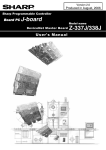
Version 1.2
Produced in Oct. 2005
Sharp Programmable Controller
Board PC J-board
Z-300 series
Model name
Communication Board : Z-331J/332J/333J
User's Manual
Sharp Programmable Controller
Board PC J-board
Model name
CPU Board 1:Z-511J
CPU board with communication function
User's Manual / Hardware version
We thank you for your purchase of SHARP Programmable Controller "J-board: Z-300 Series." This book,
Z-331J/332J/333J User’s Manual, mainly describes hardware contents such as specifications and system
configuration of the communication board.
Before using the communication board, we ask you to carefully read "JW-21CM User’s Manual." and "JW23LM User’s manual" together with this manual.
See the "J-board Z-300 series Z-311J/312J, Z-321J User's Manual: Hardware version" covering the installation methods and basic use of this board.
Models covered by this manual
Model
Details
name
Z-331J Communication board 1: Data link function (CM) + I/O link master station function (LM)
Z-332J Communication board 2: Data link function (CM)
Z-333J Communication board 3: I/O link master station function (LM)
Note
- Should you have any questions or inquires, please feel free to contact one of our dealers, or our
service department.
- Copying this manual in part of in total is prohibited.
- The contents of this manual may be revised without notice.
Safety Precautions
Read this user's manual and attached documents carefully before installation, operation, maintenance and
checking in order to use the board correctly. Understand all of the board knowledge, safety information, and
cautions before starting to use. In this user's manual, safety precautions are ranked into "Danger" and
"Caution" as follows.
Danger
: Wrong handling may possibly lead to death or heavy injury.
Caution
: Wrong handling may possibly lead to medium, light injury, or loss on properties.
Caution , a serious result may be experienced depending on the circumstances.
Even in the case of
Anyway, important points are mentioned. Be sure to observe them strictly.
The picture signs of prohibit and compel are explained below.
:It means a don’t. For example, prohibition of disassembly is indicated as (
:It means a must. For example, obligation of grounding is indicated as (
).
).
1) Installation
Caution
• Use in the environments specified in the catalog and user's manual.
Electric shock, fire or malfunction may be caused when used in the environments of high
temperature, high humidity, dusty or corrosive atmosphere, vibration or impact.
• Install according to the instruction manual and user's manual.
Wrong installation may cause drop, trouble or malfunction.
• Never admit wire chips or foreign matter.
Or fire, trouble or malfunction may be caused.
2) Wiring
Compel
• Be sure to ground.
Unless grounded, electric shock or malfunction may be caused.
Caution
• Wiring should be done by a qualified electrician.
Wrong wiring may lead to fire, trouble or electric shock.
3) Use
Danger
• Assemble the emergency stop circuit and interlock circuit outside of the J-board and integrate the
J-board's halt output. Otherwise the machine breakdown or accident may be caused by the
trouble of the programmable controller.
• Turn OFF the power source before detaching or attaching the module.
Or electric shock, malfunction or trouble may be caused.
Caution
• Manipulation for program change, forced output, RUN or STOP during operation should be done
with particular care by confirming safety. Misoperation may lead to machine trouble or accident.
• Follow the power input order specified. Otherwise, the J-board malfunctions and damages
machines or cause an accident.
4) Maintenance
Prohibit
• Don’t disassemble or modify.
Or fire, trouble or malfunction may be caused.
Caution
• Make sure to turn OFF the power before removing /installing the board, installing the connectors,
or changing the switch settings.
Table of contents
Page
Chapter 1: Outline ...................................................................................................................................... 1
Chapter 2: Precautions for use ................................................................................................................ 1
Chapter 3: Product design ...................................................................................................................... 2
Chapter 4: System configuration
4-1. Basic configuration / limitation for installation ................................................................. 3
4-2. DL1 data link system ........................................................................................................... 4
4-3. DL9 data link system ........................................................................................................... 5
4-4. M-net system ......................................................................................................................... 6
4-5. Computer link system ......................................................................................................... 7
4-6. I/O link system ...................................................................................................................... 8
Chapter 5: Specifications
5-1. General specifications (common specifications) ............................................................. 9
5-2. Data link function (CM section) ...........................................................................................9
5-3. I/O link master station function (LM section) ................................................................... 10
Chapter 6: Name and description of each part
6-1. Z-331J: Communication board 1 ....................................................................................... 11
6-2. Z-332J: Communication board 2 ...................................................................................... 12
6-3. Z-333J: Communication board 3 ...................................................................................... 13
Chapter 7: Board size ............................................................................................................................. 14
Chapter 8: Wiring communication lines ............................................................................................... 15
Chapter 9: I/O relay allocation ................................................................................................................ 16
Chapter 10: Setting switch and parameter settings
10-1. Working with a DL1 data link ........................................................................................... 18
10-2. Working with a DL9 data link ........................................................................................... 19
10-3. Working with M-net ........................................................................................................... 20
10-4. Working with a Computer link ..........................................................................................22
10-5. Working with an I/O link master station (LM) ................................................................. 23
Chapter 11: Indicator lamps ....................................................................................................................24
1. Outline
The Z-331J/332J/333J are communication boards for the J-board programmable controller: Z-300 series (hereafter simply referred to as "the J-board").
You can use these modules to construct various communication systems such as a "data link between
PLCs," a "computer link between host computers," or an "I/O link." Also, these boards let you use the Jboard in a system that combines the Sharp JW series and ZW series PLCs.
2. Precautions for use
Precautions for installation
Never install J-board in the following locations.
· Where proximate to any heat generating object, or ambient temperature exceeding 0 to 55˚C range
(at storage -20 to 70˚C).
· Where temperature rapidly changes and gives dew condensation.
· Where there is corrosive or flammable gas.
· Where it directly receives vibration or shocks.
· Where exposed to dust, iron powder, or salty atmosphere.
(In conditions where the printed circuit boards of the J-board may be directly affected by these
causes, make sure to provide an appropriate external case to cover the J-board.)
· Where it is proximate to high voltage equipment, driving power tools, large open/close surge generating devices, and their wirings.
Precautions at use
· Construct an emergency stop circuit externally to prevent damage to machines and personnel and
connect with a halt output of the J-board.
· As the J-board is board structure and it’s electronic parts are exposed, be careful when handling.
1 Before you touch the board directly, be sure to eliminate static electricity in your body.
2 Do not touch directly with dirty hands such as stacked oil etc.
3 Do not put the board alone directly on conductive objects such as metallic boards.
4 Be careful not to apply excessive force to each switch, connector, terminal block of the J-board.
· Make sure to turn OFF the power to all of the modules before connecting the board, installing or
removing the connectors, or changing the settings on the switches.
Precautions for grounding
Provide class-3 grounding independently for FG terminal of the J-board (on a terminal block of the
CPU board). Do not use with a high voltage ground line in common.
Precautions for wiring work
· Be sure to follow our recommendation for communication cables. (Use of cables other than the
recommended cables may cause improper communication in certain conditions.)
· Do not run communication cables parallel to or close to power lines, high voltage lines, or I/O cables.
· Never connect multiple communication cables from a single point.
· Make sure to turn ON the termination resistance switch on the last station in a circuit.
[Example of incorrect wiring]
[Example of good wiring]
End station
End station
Relay terminals
Turn ON the termination
resistance switch
-1-
Turn ON the termination
resistance switch
3. Product design
Z-331J: Communication board 1
16.6mm
Data link section
(CM)
L1
L2
SHIELD
FG
Accessories
Standoff used to attach the PC board to the fixing bracket
Standoff
(15 mm + 6 mm protrusion): 4 pieces
I/O link master station
section
(LM)
Screw (Semuth M3 x 6 mm): 4 pieces
L1
L2
SHIELD
FG
Screw
Z-332J: Communication board 2
Data link section
(CM)
L1
L2
SHIELD
FG
16.6mm
Accessories
Standoff used to attach the PC board to the fixing bracket
Standoff
(15 mm + 6 mm protrusion): 4 pieces
Screw (Semuth M3 x 6 mm): 4 pieces
Screw
Z-333J: Communication board 3
16.6mm
Accessories
Standoff used to attach the PC board to the fixing bracket
Standoff
(15 mm + 6 mm protrusion): 4 pieces
Screw (Semuth M3 x 6 mm): 4 pieces
Screw
I/O link master station
section
(LM)
L1
L2
SHIELD
FG
-2-
4. System configuration
4-1. Basic configuration / limitation for installation
Stacking structure
(Connectable up to four I/O boards
or communication boards)
Personal computer,
NC liquid crystal
terminal or similar
devices.
Communication board
Communication board
Support
tool
I/O board
I/O board
CPU board
CN (15P)
CN(9P)
Up to two communication
boards can be installed.
Terminal block
(7P)
Proprietary cable
(JW-22KC/24KC)
Upper stream communication
port (RS-232C) 1 : 1
Upper stream communication port
(RS-422A) N : 1
* Either RS-232C or 422A
standards can be used
24 VDC in
for communication with
FG
a host controller.
(Simultaneous use of
both standards is not
possible.)
PG port
Limitations when installing a communication board
1. Up to two sets of communication board can be installed. (When I/O boards are included, up to 4 sets
can be installed.)
2. Only one communication board with an LM section (I/O link master station function) can be installed.
<Acceptable combinations when using two communication boards>
Z-331J: Communication board 1 (LM + CM)
+
Z-332J: Communication board 2 (CM)
Z-332J: Communication board 2 (CM)
+
Z-332J: Communication board 2 (CM)
Z-332J: Communication board 2 (CM)
+
Z-333J: Communication board 3 (LM)
* For I/O assignment details, see section 9, "I/O relay allocation," in this manual.
-3-
4-2. DL1 data link system
* The Z-331J and Z-332J can be used for this system.
Number of stations that can be connected: Maximum of 16 modules.
Total extension distance: 1 km.
Data transfer speed: 153.6 kbps.
Number of link points: Maximum 64 bytes
* If JW21CM or J-board is used as master module, the number of link points per station is limited by
the number of stations connected.
J-board
JW20, JW20H
JW30H
J-board
Communication
board
I/O board
CPU board
Communication
board
JW50/70/100
JW50H/70H/100H
I/O board
CPU board
JW-21CM
JW-10CM
[Communication method for DL1 data link]
The DL1 data link uses a communication method to send data between the master module and a slave
module, and between slave modules, as shown below.
Master station
(00 station)
Slave station 01
Own station
sending data
Slave station 02
Slave station 03
Receiving data
from master station
Receiving data
from master station
Receiving data
from master station
Receiving data from
slave station 01
Own station
sending data
Receiving data from
slave station 01
Receiving data from
slave station 01
Receiving data from
slave station 02
Receiving data from
slave station 02
Own station
sending data
Receiving data from
slave station 02
Receiving data from
slave station 03
Receiving data from
slave station 03
Receiving data from
slave station 03
Own station
sending data
-4-
4-3. DL9 data link system
* The Z-331J and Z-332J can be used for this system.
Number of stations that can be connected: Maximum of 16 modules.
Total extension distance: 1 km.
Data transfer speed: 153.6 kbps.
Number of link points: Maximum 512 bytes
* If JW21CM or J-board is used as master module, the number of link points per station is
limited by the number of stations connected.
J-board
JW20, JW20H
JW30H
J-board
Communication
board
I/O board
CPU board
Communication
board
JW50/70/100
JW50H/70H/100H
I/O board
CPU board
JW-21CM
JW-10CM
[Communication method for a DL9 data link]
The DL9 data link uses a communication method for sending and receiving data between a master and a
slave station.
* This method cannot be used for direct communication between slave stations.
Master station (00 station)
Slave station 01
Sending data to
slave station 01
Receiving data
from master station
Receiving data from
slave station 01
Sending data to
master station
Slave station 02
Sending data to
slave station 02
Receiving data
from master station
Receiving data from
slave station 02
Sending data to
master station
Slave station 03
Sending data to
slave station 03
Receiving data
from master station
Receiving data from
slave station 03
Sending data to
master station
-5-
4-4. M-net system
* The Z-331J and Z-332J can be used for this system.
Number of stations that can be connected: Maximum of 8 modules.
Total extension distance: 1 km.
Data transfer speed: 19.2 kbps/ 38.4kbps.
Number of link points: Maximum 64 bytes
J-board
Communication
board I/O board
CPU board
J-board
Communication
board I/O board
CPU board
JW20,
JW20H JW50/70/100
JW30H JW50H/70H/100H
Others, Mnet specification
equipment
JW-21CM
JW-10CM
[Communication method for M-net ]
The M-net uses a communication method for sending and receiving data between a master and a slave
station.
* This method cannot be used for direct communication between slave stations.
Master station (00 station)
Slave station 01
Sending data to
slave station 01
Receiving data
from master station
Receiving data from
slave station 01
Sending data to
master station
Slave station 02
Sending data to
slave station 02
Receiving data
from master station
Receiving data from
slave station 02
Sending data to
master station
Slave station 03
Sending data to
slave station 03
Receiving data
from master station
Receiving data from
slave station 03
Sending data to
master station
* M-net is a communication system used to create a data link between a programmable controller and other
equipment. It is a communication conform to the "Standard for the interface between modules."
-6-
4-5. Computer link system
* The Z-331J and Z-332J can be used for this system.
No. of connected stations: Max. 32 stations
Total extension length: 1 km
Transfer rate: 300 to 19200 bps
Host device
Personal computer,
monitor,etc
J-board
J-board
Communication
board
I/O board
CPU board
Communication
board
JW20, JW20H
JW30H
JW50/70/100
JW50H/70H/100H
I/O board
CPU board
JW-21CM
JW-10CM
[Computer link communication system]
The computer link is a communication method in which the J-board responds to commands from a host
personal computer and display unit, as shown in the figure below.
Host
J-board or JW-PLC (station No. 01)
Command
Personal computer,
monitor, etc.
Response
J-board or JW-PLC (station No. 02)
Command
Response
J-board or JW-PLC (station No. 03)
Command
Response
-7-
4-6. I/O link system
* The Z-331J and Z-333J can be used for this system.
Number of stations that can be connected: Maximum of 32 modules.
Total extension distance: 1 km.
Data transfer speed: 172.8kbps.
Number of I /O link points: Maximum 504 points
Communication
board I/O board
CPU board
I/O link
slave module
I/O link
slave module
I/O link
slave module
Others.
valve unit etc.
[I/O link communication system]
The I/O link is a communication method in which the master station communicates with slave stations as
remote I/Os.
Master station
コ0100
*Status
コ0101
Slave station 01
(when 8-point input is used)
Slave station 02
(when 8-point output is used)
コ0102
Slave station 03
(when 16-point input is used)
コ0103
コ0104
Slave station 05
(when 16-point output is used)
コ0105
コ0106
コ0107
*"Status" is an area to store communication information such as error codes.
-8-
5. Specifications
5-1. General specifications (common specifications)
Item
Specifications
Ambient operating temperature /
0 to 55oC / 35 to 90%RH (non condensing)
humidity
Ambient storage temperature /
-20 to 70oC / 35 to 90%RH (non condensing)
humidity
Equivalent to JISC-0911, Vibration width 0.15 mm (10 to 58 Hz) , 1G
Vibration
(55 to 150 Hz) , 2 hours each on the X,Y and Z axes.
Shock
Equivalent to JISC-0912, 10G , 3 times each on the X, Y and Z axes
1000 Vp-p , 1 µs (using a noise simulator: Charge placed on the
Noise immunity
power line)
Installation
Any orientation
Grounding
Class 3 ground
Z-331J
170 mA (approximately 180 g)
5V current
consumption
Z-332J
100 mA (approximately 180 g)
(weight)
Z-333J
80 mA (approximately 180 g)
5-2. Data link function (CM section)
* For the Z-331J and Z-332J
DL1
data
link
Item
Communication
standard
Data transfer speed
Specifications
EIA RS-485 or equivalent
153.6 kbps
Equivalent to JIX X-5104 High Level Data Link Control procedure
SW0=2 Data transfer format (HDLC) frame structure. Error detection method: CRC
Communication
Shielded twisted pair cables. Total cable extension length: Maximum 1
circuit
km ( party line connection)
Number of stations
Maximum of 16 (1 master and 15 slave stations)
supported
Maximum of 64 bytes
*If the master station is a JW-21CM, Z-331J, or Z-332J, the following
limitations apply: If the
Number of link bytes Number of slave stations is 1: 32 bytes per station
Number of slave stations is 2 to 3: 16 bytes per station
Number of slave station is 4 to 7: 8 bytes per station
Number of slave station is 8 to 15 : 4 bytes per station
Link area
Specified on SW8 (module number switch.)
DL9
Communication
EIA RS-485 or equivalent
standard
SW0=3 Data transfer speed 153.6 kBPS
Equivalent to JIX X-5104 High Level Data Link Control procedure
Data transfer format
(HDLC) frame structure. Error detection method: CRC
Communication
Shielded twisted pair cables. Total cable extension length: Maximum 1
circuit
km (party line connection)
Number of stations
Maximum of 16 (1 master and 15 slave stations)
supported
Maximum of 512 bytes
*If master station is JW-21CM, Z-331J, or Z-332J, the following
limitations apply : If the
Number of link bytes Number of slave stations is 1 to 2: 128 bytes per station
Number of slave stations is 3 to 4: 64 bytes per station
Number of slave station is 5 to 8: 32 bytes per station
Number of slave station is 9 to 15 : 16 bytes per station
Link area
Specified with SW8 (module number switch)
-9-
M-net
Communication
standard
SW0=7 Data transfer speed
Data transfer format
Computer
link
Communication
circuit
Number of stations
supported
Number of link bytes
Link area
Communication
standard
Data transfer speed
SW0=4 Data transfer format
Communication
circuit
Number of stations
supported
EIA RS-485 or equivalent
19.2 kBPS/38.4 kBPS
Same as M net (interface between modules). Start (1) + data (7) + Even
parity (1) +Stop (1)
Shielded twisted pair cables. Total cable extension length: Maximum 1
km (party line connection)
Maximum of 8 (1 master and 7 slave stations)
Maximum of 64 bytes
Specified as a parameter (specify the parameter address using SW8)
EIA RS-485 or equivalent
300, 600, 1200, 2400, 4800, 9600, 19200 BPS
Start-stop synchronization. Start (1) + data (7) + parity (1) + stop (2).
Characters used: ASCII letters and numbers
Shielded twisted pair cables. Total cable extension length: Maximum 1
km (party line connection)
*Wiring method : 2-line system (4-line system is not available)
Maximum of 32 (1 master and 31 slave stations)
5-3. I/O link master station function (LM section)
* For the Z-331J and Z-333J
Item
I/O link Communication standard
master Data transfer speed
station
Transfer format
Specifications
EIA RS-485 or equivalent
172.8 kbps
Start-stop synchronization. Error detection method: Parity and
transfer verification
Shielded twisted pair cables. Total cable extension length:
Communication circuit
Maximum 1 km (party line connection)
Number of stations supported Maximum of 32
Number of link points
Maximum of 504
I/O ink area
コ 0100 to 0177 (Flag area: コ1570 to 1571)
-10-
6. Name and description of each part
6-1. Z-331J: Communication board 1
SWA
2 1
ON
I/O bus connector
SWA
SW4 SW0
CN1
SW3 4
3
2
1
SW8
CM section
SW1
SW2
ON
SW7
- When installing one communication
board, use the unit with this switch set
to the default (all ON).
- When installing two communication
boards, set SWA-1 of the 2nd
communication board OFF.
Assignment of CM section LEDs
CM (Green)
SD (Green)
RD (Green)
RS (Green)
T (Green)
ER (Red)
FT (Red)
L1
L2
S
*
FG
LM section
SW3
ON
SW4
T2
L1
L2
Communication data
Shielded terminal (* Connected to
the FG terminal internally)
Ground terminal
Assignment of LM section LEDs
CM (Green)
SY (Green)
HL (Green)
CH (Green)
MS (Green)
ER (Red)
FT (Red)
SE (Red)
ME (Red)
Communication data
S
SW2
*
Shielded terminal (* Connected to
the FG terminal internally)
FG
Ground terminal
1 2 4 10 20 40 SY T
Switches on the CM section
SW
No.
SW details
Default
DL1 data link
DL9 data link
M net
computer link
SW0
0
2
3
7
4
SW1
0
Station No. (lower digit) Station No. (lower digit) Station No. (lower digit) Station No. (lower digit)
SW2
0
Station No. (upper digit) Station No. (upper digit) Station No. (upper digit) Station No. (upper digit)
1 OFF
OFF (not used)
OFF (not used)
OFF (not used)
OFF (not used)
OFF (only 2-wire
2 OFF
OFF
OFF
system is usable)
Total number of link
SW3
Communication
mode
3 OFF
OFF
bytes (when only used
OFF
when an error occurs
as master station)
Parity
4 OFF
OFF
OFF
(Even: OFF, Odd: ON)
SW4
0
SW7
SW8
OFF
0
Number of slave
Number of slave
stations (when only
stations (when only
used as master station) used as master station)
Termination resistance Termination resistance
Module No. SW
Module No. SW
Data transfer speed
Data transfer speed
Termination resistance
Module No. SW
Termination resistance
Module No. SW
Switches on the LM section
Switch No. Default setting
Switch details
SW2
All OFF
Number of bytes in the I/O link
SW3
1
Mode change switch (select the communication mode)
SW4
OFF
Termination resistance
-11-
SW2
1 2 4 10 20 40 SY T
6-2. Z-332J: Communication board 2
SWA
2 1
ON
I/O bus connector
SWA
SW4 SW0
CN1
SW3 4
3
2
1
CM section
Assignment of CM section LEDs
SW8
SW1
SW2
ON
SW7
T1
L1
L2
S
*
- When installing one communication
board, use the unit with this switch
set to the default (all ON).
- When installing two communication
boards, set SWA-1 of the 2nd
communication board to OFF.
CM (Green)
SD (Green)
RD (Green)
RS (Green)
T (Green)
ER (Red)
FT (Red)
Communication data
Shielded terminal (* Connected
to the FG terminal internally)
FG
Ground terminal
Switches on the CM
SW No.
SW details
Default
DL1 data link
DL9 data link
M net
computer link
SW0
0
2
3
7
4
SW1
0
Station No. (lower digit) Station No. (lower digit) Station No. (lower digit) Station No. (lower digit)
SW2
0
Station No. (upper digit) Station No. (upper digit) Station No. (upper digit) Station No. (upper digit)
1 OFF
OFF (not used)
OFF (not used)
OFF (not used)
OFF (not used)
OFF
(only 2-wire
2 OFF
OFF
OFF
system is usable)
Total number of link
SW3
mode
3 OFF
OFF
bytes (when only used Communication
OFF
when
an
error
occurs
as master station)
Parity
4 OFF
OFF
OFF
(Even: OFF, Odd: ON)
SW4
0
SW7
SW8
OFF
0
Number of slave
Number of slave
stations (when only
stations (when only
Data transfer speed
used as master station) used as master station)
Termination resistance Termination resistance Termination resistance
Module No. SW
Module No. SW
Module No. SW
-12-
Data transfer speed
Termination resistance
Module No. SW
6-3. Z-333J: Communication board 3
SWA
2 1
ON
I/O bus connector
SWA
- When installing one communication
board, use the unit with this switch
set to the default (all ON).
- When installing two communication
boards, set SWA-1 of the 2nd
communication board to OFF.
CN1
LM section
SW3
ON
SW4
T2
L1
L2
S
SW2
*
FG
1 2 4 10 20 40 SY T
Switches of the LM section
Switch No. Default setting
Switch details
SW2
All OFF
Number of bytes in the I/O link
Mode change switch (select the
SW3
1
communication mode)
SW4
OFF
Termination resistance
-13-
Assignment of LM section LEDs
CM (Green)
SY (Green)
HL (Green)
CH (Green)
MS (Green)
ER (Red)
FT (Red)
SE (Red)
ME (Red)
Communication data
Shielded terminal (* Connected
to the FG terminal internally)
Ground terminal
SW2
1 2 4 10 20 40 SY T
7. Board size
5 mm
100 mm
25 mm
* 5 mm
D2
D
170 mm
CPU board *
D2
Standoff hole
4-f4
W
I/O board or
communication
board
D2
Board size
D2
15 mm
In case of fixing bracket A
5 mm
* CPU board should be installed on the top.
H
Board size (bracket sizes are not included)
Board type
H
Z-331J: Communication board 1
Z-332J: Communication board 2
Z-333J: Communication board 3
117.5 mm
117.5 mm
117.5 mm
W
D
Weight
180 mm
180 mm
180 mm
16.6 mm (D2)
16.6 mm (D2)
16.6 mm (D2)
Approx.180 g
Approx.180 g
Approx.180 g
* The weight includes the standoff and screws.
For building up of J-board, assemble the boards using the attached standoffs and screws as shown
below.
[Assembly drawing]
Screw (Semuth M3 X 6 mm)
Attached to each of board.
1
CN
CPU board
Standoff: 15 mm/20 mm
Attached to I/O board,
communication board
N1
C
I/O board
(Communication board)
Standoff: 15 mm/20 mm
Attached to I/O board,
communication board
1
CN
I/O board
(Communication board)
Standoff: 10 mm
Attached to CPU board
Fixing bracket A
Screw (Semuth M3 X 6 mm)
Attached to each of board.
Notes For connecting between the boards, match position of each connection connector (CN1)
and secure their inserts. For removal, be careful not to forcibly pull them in incorrect direction.
[Required tools for building up]
- Phillips screw driver
- Box (hex.) driver: for 5.5 mm
-14-
Standoff shape
5.5 mm
8. Wiring communication lines
When wiring the communication cables, use crimped terminals that meet the following conditions.
Applicable crimping
terminal size
Communication
board
6 mm
a
b
a
b
a = 6 mm or less
b = 3 mm or less
M3 self-up screw
Only use shielded twisted pair cables recommended by us for communication cables.
L1
L1
L1
L2
L2
L2
SHIELD
SHIELD
SHIELD
FG
FG
FG
Communication
cable
Recommended cables
Hitachi Cable, Ltd.: S-IREV-SW2*0.5
Fujikura Ltd.: RG-22B/U
-15-
9. I/O relay allocation
8 bytes are occupied by the units for assignment as I/O relays for the communication boards.
I/O relays are assigned as dummies on the communication boards and are not functional. However,
please note that these assignments can affect the I/O relay addresses on other I/O boards.
[I/O address assignment for each communication board]
* An example using the 1st communication board (SWA-1 = ON, SWA-2 = ON)
Z-332J:
Z-333J:
Z-331J:
Communication board 2
Communication board 3
Communication board 1
Assignment I/O relay
address
コ 0000
LM section
コ 0001
コ 0002
CM section
コ 0003
コ 0004
Dummy
(vacant)
コ 0005
コ 0006
Dummy
(vacant)
コ 0007
Installed
address
R = 0, S = 0
R = 0, S = 1
R = 0, S = 2
R = 0, S = 3
Assignment I/O relay
address
コ 0000
Dummy
(vacant)
コ 0001
コ 0002
CM section
コ 0003
コ 0004
Dummy
(vacant)
コ 0005
コ 0006
Dummy
(vacant)
コ 0007
Installed
address
R = 0, S = 0
R = 0, S = 1
R = 0, S = 2
R = 0, S = 3
I/O relay
Assignment address
コ 0000
LM section
コ 0001
コ 0002
Dummy
(vacant)
コ 0003
コ 0004
Dummy
(vacant)
コ 0005
コ 0006
Dummy
(vacant)
コ 0007
Installed
address
R = 0, S = 0
R = 0, S = 1
R = 0, S = 2
R = 0, S = 3
[I/O relay assignment when using two communication boards]
Possible combinations when using two communication boards
1st
I/O
communication relay
board
address
コ 0000
SWA-1 = ON
コ 0001
SWA-2 = ON
コ 0002
コ 0003
コ 0004
2 1
コ 0005
ON
コ 0006
コ 0007
2nd
I/O relay
communication
address
board
コ 0010
SWA-1 = OFF
コ 0011
SWA-2 = ON
コ 0012
コ 0013
コ 0014
2 1
ON
コ 0015
コ 0016
コ 0017
Installed
address
Z-331J
Z-332J
Z-332J
R = 0, S = 0
LM section
Dummy
(vacant)
Dummy
(vacant)
R = 0, S = 1
CM section
CM section
CM section
R = 0, S = 2
Dummy
(vacant)
Dummy
(vacant)
Dummy
(vacant)
R = 0, S = 3
Dummy
(vacant)
Dummy
(vacant)
Dummy
(vacant)
Installed
address
Z-332J
Z-332J
Z-333J
R = 0, S = 4
Dummy
(vacant)
Dummy
(vacant)
LM section
R = 0, S = 5
CM section
CM section
Dummy
(vacant)
R = 0, S = 6
Dummy
(vacant)
Dummy
(vacant)
Dummy
(vacant)
R = 0, S = 7
Dummy
(vacant)
Dummy
(vacant)
Dummy
(vacant)
Notes
1. When using a communication board, set SW1 (module No.) on the I/O board starting at "1."
If the SW1 (module No.) on an I/O board is set to "0," an "I/O verification error: Error code 60" will occur.
2. Up to two communication boards can be connected. Be careful that depending on the type of communication board, there are some limitations to the working combinations.
3. When one communication board is used, use the setting for the1st board (set all of the SWA switches
ON). If this board is set up as the 2nd board, an "I/O verify error: Error code 60" will occur.
-16-
[Setting example]
ON
OFF
SWA
2 1
I/O relay address
コ0010 to 0017
Communication board
Communication board
2 1
SW1(RACK NO.)
コ0000 to 0007
64 points I/O board
1 2 3
64 points I/O board
1 2 3
コ0030 to 0037
コ0020 to 0027
CPU board
ON
OFF
When using a communication board, set SW1 (module No.) on the I/O board starting at "1."
If the SW1 (module No.) on an I/O board is set to "0," an "I/O verification error: Error code 60" will occur.
When set up as described above, the relationship between the I/O relay addresses and the installed addresses are as follows.
SW1(Module no.)
I/O board 1
SWA/SW2
SW2
1 2 3
2 1
SW2
I/O board 2
1 2 3
2 1
SWA
2 1
Communication
board 3
SWA
Communication
board 4
2 1
-17-
I/O relay address Installed address
R = 1, S = 0
コ 0020, 21
R = 1, S = 1
コ 0022, 23
0024,
25
R
= 1, S = 2
コ
R = 1, S = 3
コ 0026, 27
0030,
31
R
= 2, S = 0
コ
0032,
33
R
= 2, S = 1
コ
R = 2, S = 2
コ 0034, 35
R = 2, S = 3
コ 0036, 37
0000,
01
R
= 0, S = 0
コ
0002,
03
R
= 0, S = 1
コ
R = 0, S = 2
コ 0004, 05
R = 0, S = 3
コ 0006, 07
0010,
11
R
= 0, S = 4
コ
0012,
13
R
= 0, S = 5
コ
R = 0, S = 6
コ 0014, 15
R = 0, S = 7
コ 0016, 17
10. Switch and parameter settings
10-1. Working with a DL1 data link
* Z-331J and Z-332J should be used.
SW NO.
Setting details
SWA-1 When using more than one board.
Set SWA-1 on the 2nd communication board OFF (SWA-2 is always ON)
SW0
Set the function to "2."
SW1
Set the station number (lower digit) Specify the station number (00 to 17) in octal.
Ex.: Master station -> 00
SW2
Set the station number (upper digit)
Slave station 6 -> 06
SW3
Set all to OFF.
1 OFF (Not used)
2 OFF
3 OFF
4 OFF
SW4
Specify the number of slave stations connected ( the number of link bytes will be
Only set determined, accordingly)
when
Number of
Number of
Number of
Number of
Setting slave
the
stations link bytes
Setting slave stations link bytes per
board is
connected
per station
connected
station
a
0
8
8
master
1
1
32 bytes
9
9
station
2
2
A
10
16 bytes
3
3
B
11
4 bytes
4
4
C
12
5
5
D
13
8 bytes
6
6
E
14
7
7
F
15
* If a JW-10CM is used for the master station, the number of link bytes
per station can be freely assigned, up to 128 bytes.
* When "0" is specified, a setting error will occur.
(For details, see the JW-10CM user's manual)
SW8
Specify a data link area and a flag area
(Module
Setting
Data link area
Communication flag area
No.
0
15000 to 15017
switch)
コ 1000 to 1077
1
15100 to 15117
コ 1100 to 1177
2
15200 to 15217
コ 1200 to 1277
3
15300 to 15317
コ 1300 to 1377
4
15400 to 15417
コ 1400 to 1477
5
89000 to 89077
15500 to 15517
*Setting switch 6 to 9 will cause a setting error.
SW7
Enabling the termination resistance
Set this switch on last station to ON (provides termination resistance). Set this
switch on stations in between to OFF (no termination resistance).
Assignment of communication flags (numbers in the table are the station numbers of the PLCs)
コ 15*0
7
07
17
6
06
16
5
05
15
4
04
14
3
03
13
2
02
12
1
01
11
0
00
10
"*" will be determined by setting SW8.
* For details about the DL1 data link, see the "JW-21CM User's Manual."
-18-
Bit address
Setting
10-2. Working with a DL9 data link
* Only set when the board
is a master station
* Only set when the board is a master
station
* Z-331J and Z-332J should be used.
Sw
Setting details
Setting
No.
SWA-1 When using more than one board.
Set SWA-1 on the 2nd communication board OFF (SWA-2 is always ON)
SW0
Set the function to "3."
SW1
Set the station number (lower digit) Specify the station number (00 to 17) in octal.
Ex.: Master station -> 00
SW2
Set the station number (upper digit)
Slave station 6 -> 06
SW3
Specify the total number of link bytes
Number of slave
Setting
stations
No.
to
Link area on the
of
1
2 34to 58to 915
master station
bytes
1
2
3
4
Number of link bytes per
station
コ
コ 1100-, コ 1200-,
OFF OFF OFF -> 64
32 16 8
4
2 1000-,
コ1300-,コ 1400-, 89000コ
コ 1100-, コ 1200-,
Not OFF OFF ON -> 128 64 32 16 8
4 1000-,
コ1300-, 89000used
OFF ON OFF -> 256 128 64 32 16 8 コ1000-,コ 1100-, 89000OFF ON ON -> 512 128 128 64 32 16 Limited to 89000* The number of link bytes per station is each number of bytes for sending (master
to slave) and receiving (slave to master) data.
* If a JW-10CM is used for the master station, the number of link bytes per station
can be freely assigned, zup to 128 bytes. (For details, see the JW-10CM user's
manual)
SW4
Specify the number of slave stations connected (the number of link bytes will be
determined, accordingly)
of boards
of boards
of boards
Setting No.
Setting No.
Setting No.
connected
connected
connected
0
6
6
C
12
1
1
7
7
D
13
2
2
8
8
E
14
3
3
9
9
F
15
4
4
A
10
5
5
B
11
(Module
No. switch)
SW8
Specify a data link area and a flag area
Setting Data link
CommuniInitial sequence Link operation
area
cation monitor flag complete flag
flag (master
(slave station)
(master station)
station)
0
15000
15001
15003
コ 1000 to
1
15100
15101
15103
コ 1100 to
2
15200
15201
15203
コ 1200 to
3
15300
15301
15303
コ 1300 to
4
15400
15401
15403
コ 1400 to
5
89000
15500
15501
15503
Monitor flag
(master station)
15020 to 15077
15120 to 15177
15220 to 15277
15320 to 15377
15420 to 15477
15520 to 15577
*Setting switch 6 to 9 will cause a setting error.
Enabling the termination resistance
Set this switch on last station to ON (provides termination resistance). Set this switch
on stations in between to OFF (no termination resistance).
Assignment of communication flags (numbers in the table are the station numbers of the PLCs)
7 6 5 4 3 2
1 0
<-Bit address
"*" will be deter07 06 05 04 03 02 01 コ 15*2
Communication monitor flag
15*3
17
16
15
14
13
12
11
10
コ
mined by setting
07 06 05 04 03 02 01 コ 15*4
PLC operation status monitor flag [I] SW8.
17 16 15 14 13 12 11 10
コ 15*5
コ 15*6
07 06 05 04 03 02 01 PLC operation status monitor flag [II]
コ15*7
17 16 15 14 13 12 11 10
* For details about the DL9 data link, see the "JW-21CM User's Manual."
-19SW7
10-3. Working with M-net
* Z-331J and Z-332J should be used.
SW NO.
Setting details
SWA-1 When using more than one board.
Set SWA-1 on the 2nd communication board OFF (SWA-2 is always ON)
SW0
Set the function to "7."
SW1
Set the station number (lower digit) Specify the station number (00 to 17) in octal.
Ex.: Master station -> 00
SW2
Set the station number (upper digit)
Slave station 6 -> 06
SW3
Specify communication mode
Only set
1 OFF (Not used)
when
2 OFF
the
board is
3 Operation mode when a communication error occurs. OFF: Stop operation.
a master
ON: Continues communication with other normal stations.
station
4 OFF
Setting
SW4
Setting data transfer speed
Setting Data transfer speed
0
19.2 kBPS
7
38.4 kBPS
* Setting this switch to other than "0" or "7" will cause a setting error.
* The data transfer speed must be the same on all of the station
SW8
Specify a data link area, parameter storage area, communication selection register,
(Module and a flag area.
No.
Communication
Error flag
Data
Parameter storage
switch)
selection
register
*Only when
Setting link
area (parameter for
*Only when used as a used as a
area
CPU option)
master station
master station
0
O-SW0:000 to 017
15010
コ1000コ 1500
1
O-SW1:000 to 017
15110
コ1100コ 1510
2
O-SW2:000 to 017
15210
コ1200コ 1520
3
O-SW3:000 to 017
15310
コ 1530
コ13004
O-SW4:000 to 017
15410
コ 1540
コ14005
89000O-SW5:000 to 017
15510
コ 1550
*Setting switch 6 to 9 will cause a setting error.
SW7
Enabling the termination resistance
Set this switch on last station to ON (provides termination resistance). Set this
switch on stations in between to OFF (no termination resistance).
Assignment of the communication selection register (the numbers in the table are the slave station
numbers)
Bit address
7
6
5
4
3
2
1
0
コ 15 *0
07
06
05
04
03
02
01 Start relay
Start relay ON: Start communication
OFF: Stop communication
Communication selection relay
ON: Does not communicate with this slave station
OFF: Communicates with this slave station
Assignment of error flags (the numbers in the table are the slave station numbers)
7
6
5
4
3
2
1
0
Bit address
コ15 *1
07
06
05
04
03
02
01
00
"*" is determined by the setting on SW8.
* For details about the M-net, see the "Maintenance Manual for Interface Modules."
-20-
M-net parameter settings
Master station parameter settings
Parameter
address*
000
001
002
003
004
005
006
007
010
011
012
013
014
015
016
017
Setting details
Setting
value
Number of data bytes to transfer from the master station to slave station 01 (decimal)
Number of data bytes to transfer from slave station 01 to the master station (decimal)
Number of data bytes to transfer from the master station to slave station 02 (decimal)
Number of data bytes to transfer from slave station 02 to the master station (decimal)
Number of data bytes to transfer from the master station to slave station 03 (decimal)
Number of data bytes to transfer from slave station 03 to the master station (decimal)
Number of data bytes to transfer from the master station to slave station 04 (decimal)
Number of data bytes to transfer from slave station 04 to the master station (decimal)
Number of data bytes to transfer from the master station to slave station 05 (decimal)
Number of data bytes to transfer from slave station 05 to the master station (decimal)
Number of data bytes to transfer from the master station to slave station 06 (decimal)
Number of data bytes to transfer from slave station 06 to the master station (decimal)
Number of data bytes to transfer from the master station to slave station 07 (decimal)
Number of data bytes to transfer from slave station 07 to the master station (decimal)
Number of slave stations connected (decimal) Note
Always set to 00
Slave station parameter settings
Slave
Parameter
Setting
Setting details
station no. address*
value
000
Number of data bytes to transfer from the master station to slave station 01 (decimal)
Slave
Number of data bytes to transfer from slave station 01 to the master station (decimal)
station 01
001
000
Number of data bytes to transfer from the master station to slave station 02 (decimal)
Slave
Number of data bytes to transfer from slave station 02 to the master station (decimal)
station 02
001
000
Number of data bytes to transfer from the master station to slave station 03 (decimal)
Slave
Number of data bytes to transfer from slave station 03 to the master station (decimal)
station 03
001
000
Number
of data bytes to transfer from the master station to slave station 04 (decimal)
Slave
Number of data bytes to transfer from slave station 04 to the master station (decimal)
station 04
001
Slave
station 05
Slave
station 06
Slave
station 07
000
001
000
001
000
001
Number of data bytes to transfer from the master station to slave station 05 (decimal)
Number of data bytes to transfer from slave station 05 to the master station (decimal)
Number of data bytes to transfer from the master station to slave station 06 (decimal)
Number of data bytes to transfer from slave station 06 to the master station (decimal)
Number of data bytes to transfer from the master station to slave station 07 (decimal)
Number of data bytes to transfer from slave station 07 to the master station (decimal)
* Specify the parameters in memory on the CPU board using a support tool.
The offset address ( -SW*) for the parameters is determined by the SW8 setting.
Note Specify the number of slave stations connected, regardless of the settings in the communication relay
selection (ON/OFF).
-21-
10-4. Working with a computer link
SW NO.
SWA-1
SW0
SW1
SW2
SW3
SW4
SW8
(Module
No.
switch)
Setting details
Z-331J and Z-332J should be used.
Setting
When using more than one board.
Set SWA-1 on the 2nd communication board OFF (SWA-2 is always ON)
Set the function to "4."
Set the station number (lower digit) Specify the station number (01 to 37) in octal.
Ex.: Station No. 01 -> 01
Set the station number (upper digit)
Station No. 17 -> 17
Specify communication mode
1 Always set to OFF.
2 Always set to OFF* Used only with a 2-wire system.
3 Always set to OFF.
4 Select parity check OFF: Odd ON: Even
Setting data transfer speed
Setting
Data transfer speed
0
19200 BPS
1
9600 BPS
2
4800 BPS
3
2400 BPS
4
1200 BPS
5
600 BPS
6
300 BPS
* Setting this switch to other than "7" to "F" will cause a setting error.
* The data transfer speed must be the same on all of the station
Specify a flag area
Setting
Global address
command complete flag
0
15000
1
15001
2
15002
3
15003
4
15004
5
15005
6
15006
*Setting switch 7 to 9 will cause a setting error.
SW7
Enabling the termination resistance
Set this switch on last station to ON (provides termination resistance). Set this
switch on stations in between to OFF (no termination resistance).
* For details about computer links, see the "JW-21CM User's Manual."
-22-
10-5. Working with an I/O link master station (LM)
* Z-331J and Z-333J should be used.
SW No.
Setting details
SWA-1 When using more than one board.
Set SWA-1 on the 2nd communication board OFF (SWA-2 is always ON)
SW2
Number of I/O link bytes
1
2
4 Specify the total number of bytes occupied by all of the
10 slave station modules. (Enter as an octal number)
20
40
SY Select asynchronous or synchronous calculation of the
communication cycle and J-board ON: Synchronous
T Always set to OFF.
[An example setting 11 modules with 16 points as slave stations]
Total number of bytes = 2 bytes (16 points) x 11 modules = 22 bytes (decimal) ->
26 (octal)
1
2
4
10
20
40
SY
T
Setting
ON
SW3
Mode select switch (select a communication mode)
Communication mode 1
In
the normal case, the board checks the connection once per 100
1 cycles.
If there is a slave station that does not respond, the board will
repeat the connection check.
Communication mode 2
In the normal case, the board checks the connection once per 100
2 cycles. If there is a slave station that does not respond, the board will
assume this is a disconnected station and continue with the other,
normal slave stations.
Communication mode 3
The board checks the connection when power is first applied or the
3 CHECK relay is ON. If there is a slave station that does not respond,
the board will assume this is a disconnected station and continue with
the other, normal slave stations.
* Setting this switch to other than "1" or "2" or "3" will cause a setting error.
SW4
Enabling the termination resistance
Set this switch on last station to ON (provides termination resistance). Set this
switch on stations in between to OFF (no termination resistance).
I/O link area (コ100 to 177)
コ 0100
コ 0101
コ 0102
コ 0103
Status (input)
Slave station data (Slave station address 01)
Slave station data (Slave station address 02)
Slave station data (Slave station address 03)
コ 0176 Slave station data (Slave station address 76)
コ 0177 Slave station data (Slave station address 77)
Error flag assignment (the numbers in the table are the slave station numbers)
15707
15706
15705 15704 15703 15702
15701 15700
Read relay Operation relay
HALT CHECK Output
15717
15716
15715
15714
15713
15712
15711
Error data
15710
Input
Note There is no module no. switch for the LM section. (It is set to "0" internally.)
* For details about the I/O link, see the "JW-23LM User's Manual."
-23-
11. Indicator lamps
CM section
1 For DL1 data links, DL9 data links, and computer links
LED name
CM (green)
SD (green)
RD (green)
RS (green)
T (green)
Display condition
Goes ON during link operations (while communicating)
Goes ON while sending data
Goes ON while receiving data
Goes ON during link operations (request to send)
Goes ON while testing (used for factory inspections by the
manufacturer)
ER (red)
Goes ON when a switch setting error occurs.
FT (red)
Goes ON when the WDT times out.
Recovery
Check the switch setting.
Replace the board.
Replace the board.
2 In case of M net
LED name
CM (green)
SD (green)
RD (green)
RS (green)
T (green)
ER (red)
FT (red)
Display condition
Recovery
Goes ON during link operations (while communicating)
Goes ON while sending data
Goes ON while receiving data
Goes ON during link operations (request to send)
Goes ON while testing (used for factory inspections by the
manufacturer)
Goes ON when a switch setting error occurs.
Check the switch setting.
Check the parameter setting.
Check for a disconnection in
the communication cable.
Replace the board.
Goes ON when the WDT times out.
Replace the board.
Note There are no LEDs to display the error code. Check the error status by monitoring system memory
(#170 and up).
LM section
LED name
Display condition
Recovery
CM (green) Goes ON during link operations (while communicating)
SY (green) Goes ON when "synchronous" is selected as communication cycle
type.
HL (green) Goes ON when the internal relay (HALT) is ON.
CH (green) Goes ON when the internal relay (CHECK) is on in communication
mode 3.
MS (green) Goes ON when a communication error occurs.
See the "JW-23LM
User's Manual."
ER (red)
Goes ON when a switch setting error occurs on the master station.
Goes ON when a switch setting error occurs.
FT (red)
Goes ON when an error occurs in the master station.(Goes ON when
the WDT times out.)
ME (red)
Goes ON when a circuit error occurs in the master station.
Goes ON when a switch setting error occurs in the master station.
Goes ON when a communication error occurs.
SE (red)
Goes ON when a communication error occurs.
Note There are no LEDs to display the error code. Check the error status by monitoring the status register
(コ1571).
* For details about errors and troubleshooting, see the "JW-21CM User's Manual," "Maintenance Manual for
Interface Modules," and the "JW-23LM User's Manual".
-24-
SHARP MANUFACTURING SYSTEMS CORPORATION
♦ Information about Sharp image sensor camera and programmable controller
is available at our internet homepage
http://sharp-world.com/sms/
1.2v
10.2005
(0.1I.M.S)