1
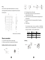
Contents LED Matrix light manual Blinder Matrix, 5x5 LED warm, Beam 6dgr, DMX3 Safety information ........................................................................................2 Dimensions...................................................................................................3 Power connection.........................................................................................4 Installation ....................................................................................................6 Control panel ................................................................................................8 Common operations.....................................................................................8 Stand alone operation ...........................................................................8 Master and slave operation ..................................................................8 DMX mode ............................................................................................9 DMX protocol..............................................................................................10 Menu...........................................................................................................12 Technical specifications..............................................................................14 STL-025 Please read the manual before installing and using this lighting Keep it for future reference 1 Thank you for purchasing our product!Upon receiving the lighting,please carefully check that there has been no damage caused in transportation. If the lighting has been damage, do not use the lighting and contact your Ensure that the air flow through fans and vents is free and unobstructed. dealer or manufacturer. Keep all combustible materials (for example fabric, wood, paper) at least 0.3 meter away from the light. Keep flammable materials well away from the fixture. This product complies with the following standards: IEC60598-1:2003 Avoid looking directly into the light source (especially those who suffer from epileptic fits) IEC60598-2-17:1984+A2:1990 When it is thunderstorm, don’t use the light and disconnect the power supply, high voltage will destroy light. Safety information The max. ambient temperature is 40 °C. When suspending the fixture above ground level, verify that the structure can hold at least 10 times the weight of all installed devices. Important Verify that all external covers and rigging hardware are securely fastened and use an approved means of secondary attachment such All operation and maintenance must be carried out in accordance with this user manual Manufacturer will not with responsibility for those operations not according as a safety cable. Verify that all screws are tightly fastened. Don’t move the cord directly. It’s only allowed with the handle to this Instruction: Verify that the voltage matches the rated voltage. Always disconnect the power before attempting to open the equipment Dimensions housing or carrying out any maintenance. Do not connect power cable of other electric products with this unit. Make sure power socket is connected with earth cable well. The earth cable of this unit is Yellow/Green one. Do not expose the fixture to rain or moisture. Verify that the feed cables are undamaged and rated for the current requirements of all connected devices before use. Never attempt to bypass the thermostatic switch or fuses. Always replace defective fuses with ones of the specified type and rating. 2 3 Note: User can order the optional handles separately from our company according application (the handles are not supplied with the product), like the below picture: Put bushing and chuck onto the cable. Prepare cable as shown above. The power cable must is a three-conductor 2.5mm2 cable. Insert the wire into the terminals and fasten the clamping device by a flat screw driver. Push insert and chuck into housing (pay attention to the guiding keyway.) Fasten bushing. the color-coding schemes and some possible pin identification schemes; if pins are not clearly identified , or if you have any doubts about proper installation , consult a qualified electrician All dimensions are in millimeter Power connection Verify that the voltage matches the rated voltage. Make sure power socket is connected with earth cable well. Wire color Conductor Symbol Brown Live L Blue Neutral N Yellow/green ground Handling Installing a Neutrik connector on a power cable 4 5 Relaying power to other devices The lightings can be linked in a chain by power cables which installed a blue and a light-gray connectors on the two ends. The light-gray connector connects to the power out socket of the first lighting, and the blue connector connects to the power in socket of the subsequent lighting, and so on. Warning! Install the safety cable to the structure and anchor the cable to 2 The power cable must is a three-conductor 2.5mm cable. the dedicated attachment point on Do not connect more than 8 lightings in total to AC mains power in one the base. The attachment point is interconnected daisy chain designed to fit a carabiner clamp. Installation Stacking the lightings vertically and horizontally by the locks on the side 6 7 Slave setting method: Control panel Press the menu to A001 position (with actually stored address). Button functions ESC UP DOWN ENTER Call the main menu, or escape the current menu(i.e. return to the upper menu and give up the selected item or parameter) Browse the menu item forward or increase the parameter Browse the menu item backward or decrease the parameter Confirm the selected item or parameter(i.e. enter the next menu, or escape the current menu and save the selected item or parameter) DMX mode In DMX mode,the lighting can controlled by controller. 1. Connect controller to DMX IN of the first lighting , connect DMX OUT of the first lighting to DMX IN of the second lighting , then connect DMX OUT of the second lighting to DMX IN of the third lighting , and so on . Insert a termination plug in the output of the last fixture on the link. (The termination plug, which is a male XLR plug with a 120 ohm, 0.25 Common operations watt resistor soldered between pins 2 and 3, “soaks up” the control signal so it does not reflect and cause interference.) Stand alone operation Press ESC button until the lighting shows SET , then press ENTER to enter the SET menu , and use UP or DOWN buttons to browse to MAAL , then press enter to enter and browse to ALON , and then press ENTER to 2. Press the menu to A001 position(with actually stored address) ,the lighting enter DMX mode . 3. Set DMX address While the lighting shows A001(with actually stored address) , press confirm , the lighting enter Stand alone mode . enter , it shows DMX , press ENTER again and use UP or DOWN Master and slave operation buttons to browse to ADDR , then press ENTER to enter and use UP 1. Connect DMX OUT of the first lighting to DMX IN of the second lighting and DOWN to adjust the DMX address and press ENTER to save it . with DMX signal cable, and then connect DMX OUT of the second In DMX mode, a fixture requiring one or more channels for control lighting to DMX IN of the third lighting, and so on. begins to read the data on the channel indicated by the start address. 2. Set one lighting to master-device,others to slave-device,then all For example, a fixture that uses 3 DMX channels and was addressed lightings run synchronously flow the master-device. to start on DMX channel 1, would read data from channels: 1, 2, 3. Master setting method : Choose start addresses so that the channels used do not overlap, and Press ESC button until the lighting shows SET, then press ENTER to note the start address selected for future reference. Note that assign enter the SET menu, and use UP or DOWN buttons to browse to the same address to the different lightings, they will receive the same MAAL, then press enter to enter and browse to MAST, and then press signal. ENTER to confirm. 8 9 185-189 190-204 205-255 DMX protocol This lighting has 3 channel modes : 25 channels mode , 5 channels mode , shutter open strobe8:random burst pulse (fast to slow) shutter open CH3 30 channels mode The default mode is 25 Channels Mode. If you want to alter it, enter DMX menu. programs 000-009 No effect 010-155 Built-in programs 156-255 No effect CH4 25 channels mode 000-255 Channel DMX value Function CH1~CH25 000-255 Individual LEDs dimmer(dark to bright) CH5 Built-in scenes 000-255 Program speed 000 Normal 001-255 Fast to slow 30 channels mode 5 channels mode Channel DMX value Function CH1 000 - 255 Global Dimmer(dark to bright) CH2 Strobe 000-005 006-064 065-069 070-084 085-089 090-104 105-109 110-124 125-129 130-144 145-149 150-164 165-169 170-184 scenes shutter open strobe1(fast to slow) shutter open strobe2:opening pulse(fast to slow) shutter open strobe3: closing pulse (fast to slow) shutter open strobe4:random strobe(fast to slow) shutter open strobe5:random opening pulse(fast to slow) shutter open strobe6: random closing pulse (fast to slow) shutter open strobe7:burst pulse(fast to slow) 10 Channel DMX value Function CH1 000 - 255 Global Dimmer(dark to bright) CH2 Strobe 000-005 006-064 065-069 070-084 085-089 090-104 105-109 110-124 125-129 130-144 145-149 150-164 165-169 170-184 shutter open strobe1(fast to slow) shutter open strobe2:opening pulse(fast to slow) shutter open strobe3: closing pulse (fast to slow) shutter open strobe4:random strobe(fast to slow) shutter open strobe5:random opening pulse(fast to slow) shutter open strobe6: random closing pulse (fast to slow) shutter open strobe7:burst pulse(fast to slow) 11 185-189 190-204 205-255 shutter open strobe8:random burst pulse (fast to slow) shutter open CH3 programs ├MAAL ; Master/stand-alone setting │ ├MAST ; Master mode No effect │ └ALON ; Stand-alone mode 010-155 Built-in programs 156-255 No effect ├TCSU ; Temperature control, it will reduce the output scenes 000-255 CH6~CH30 │ └OFF 000-009 CH4 CH5 │ ├ON Built-in scenes 000-255 Program speed │ ├TMSH after over temperature │ │ ├ON ; Enable the switch(default) │ │ └OFF ; Disable the switch 000 Normal │ └TEMP 001-255 Fast to slow │ ├CAPT ; Capture the current temperature 000-255 Individual LEDs dimmer(dark to bright) │ └TSET ; Set the value of the TC switch ├FAN │ ├FULL │ └AUTO Menu └SOFT (password protected) ; Fan speed control ; Full speed ; Auto ; Soft information 2. DMX Menu Menu Navigation SET Menu←ESC←A001→ENT→DMX Menu UP↑↓DN SET Menu←ESC←ADJ→ENT→Adjustment menu UP↑↓DN SET Menu←ESC←SCEN→ENT→Scenes menu DMX ├ADDR │ └ A001 └ CHS ├ CH25 ├ CH05 └ CH30 DMX address ; Channel mode selection ; 25-channel mode (default) ; 5-channel mode ; 30-channel mode UP↑↓DN SET Menu←ESC←PROG→ENT→Built-in program menu ADJ ├GDIM │ └000-255 └STOB └ 000-255 UP↑↓DN 1. SET Menu SET ├RELD 3. Adjustment menu ; Global dimmer ; Strobe(0=no stobe,1~255=fast to slow) ; Reload default 12 13 4. Scenes Menu SCEN ├NOM : │ └0-027 ├DIM │ └000-255 └STOB └000-255 ; ; Select scenes ; Dimmer ; Strobe(0=no stobe,1~255=fast to slow) 5. Built-in program menu PROG ├PNU │ └001-020 ├SPED │ └0-255 └GDIM └000-255 ; Built-in programs ; Select built-in program ; ; Program speed ; Global dimmer Technical specifications Voltage:100-240V, 50/60Hz Power:330W light source:25 pcs 10W white LEDs Control mode:DMX Mode、Master/slave mode Channel QTY: 5 /25 /30selected by menu IP rating: IP 20 Working temperature : -20℃~ +40℃ Dimensions: 575*575*90mm(whithout handle) Net weight: 9.6kg 14