1
Power Hawk Series 600
Closely-Coupled Programming Guide
Title was formerly “Closely-Coupled Programming Guide”
0891081-020
June 2001
Copyright 2001 by Concurrent Computer Corporation. All rights reserved. This publication or any part thereof is
intended for use with Concurrent Computer Corporation products by Concurrent Computer Corporation personnel,
customers, and end–users. It may not be reproduced in any form without the written permission of the publisher.
The information contained in this document is believed to be correct at the time of publication. It is subject to change
without notice. Concurrent Computer Corporation makes no warranties, expressed or implied, concerning the
information contained in this document.
To report an error or comment on a specific portion of the manual, photocopy the page in question and mark the
correction or comment on the copy. Mail the copy (and any additional comments) to Concurrent Computer Corporation, 2881 Gateway Drive Pompano Beach, FL 33069. Mark the envelope “Attention: Publications Department.”
This publication may not be reproduced for any other reason in any form without written permission of the publisher.
UNIX is a registered trademark of The Open Group.
Ethernet is a trademark of Xerox Corporation.
PowerMAX OS is a registered trademark of Concurrent Computer Corporation.
Power Hawk and PowerStack are trademarks of Concurrent Computer Corporation.
Other products mentioned in this document are trademarks, registered trademarks, or trade names of the
manufactures or marketers of the product with which the marks or names are associated.
Printed in U. S. A.
Revision History:
Level:
Effective With:
Original Issue
- August 1999
000
PowerMAX OS Release 4.3
Previous Issue
- March 2000
010
PowerMAX OS Release 4.3, P2
Current Issue
- June 2001
020
PowerMAX OS Release 5.1
Preface
Scope of Manual
This manual is intended for programmers that are writing applications which are distributed across multiple single board computers (SBCs) which either share the same VMEbus
or which are connected via a Real-time Clock and Interrupt Module (RCIM). Programming interfaces which allow communication between processes resident on separate single board computers in such a configuration are discussed. For information on configuring and administering these configurations, see the Power Hawk Series 600 Diskless
Systems Administrator’s Guide.
Structure of Manual
This manual consists of a title page, this preface, a master table of contents, four chapters,
local tables of contents for the chapters, one appendix, glossary of terms, and an index.
• Chapter 1, Introduction, contains an overview of closely-coupled systems
(CCS) and the programming interfaces that are unique to closely-coupled
single board computer (SBC) configurations.
• Chapter 2, Reading and Writing Remote SBC Memory, explains how to use
shared memory to read and write remote SBC memory in a cluster configuration.
• Chapter 3, Shared Memory, explains how SBCs within the same cluster
can be configured to share memory with each other.
• Chapter 4, Inter-SBC Interrupt Generation and Notification, describes how
program interfaces are available via ioctl(2) commands to interrupt
SBCs within the same cluster in an CCS system.
• Appendix A, Master MMAP Type 1 Shared Memory, describe how to map
a single region of memory on one other board into its physical address
space.
• Glossary explains the abbreviations, acronyms, and terms used throughout
the manual.
The index contains an alphabetical list of all paragraph formats, character formats, cross
reference formats, table formats, and variables.
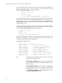
Syntax Notation
The following notation is used throughout this guide:
iii
Power Hawk Series 600 Closely-Coupled Programming Guide
italic
Books, reference cards, and items that the user must specify
appear in italic type. Special terms may also appear in italic.
list bold
User input appears in list bold type and must be entered
exactly as shown. Names of directories, files, commands, options
and man page references also appear in list bold type.
list
Operating system and program output such as prompts and messages and listings of files and programs appears in list type.
[]
Brackets enclose command options and arguments that are
optional. You do not type the brackets if you choose to specify
such option or arguments
Referenced Publications
Concurrent Computer Corporation Manuals:
0890429
0890430
0891058-reln
0890466
0890479
0891080
0891082
0890425
System Administration Manual (Volume 1)
System Administration Manual (Volume 2)
Power Hawk Series 600 Version x.x PowerMAX OS
Release Notes
(reln = release number)
PowerMAX OS Real-Time Guide
PowerMAX OS Guide to Real-Time Services
Power Hawk Series 600 Diskless System Administrator’s Guide
Real-Time Clock & Interrupt Module (RCIM)
User’s Guide
Device Driver Programming Manual
VME SBC Motorola Manuals (See Note below):
V2600A/IH1
MVME2600 Series Single Board Computer Installation and Use
Manual
V4600A/IH1
MVME4600 Series Single Board Computer Installation and Use
Manual
PPCUGA1/UM
PPCBug Firmware Package User’s Manual (Parts 1)
PPCUGA2/UM
PPCBug Firmware Package User’s Manual (Part 2)
PPCDIAA/UM
PPC1Bug Diagnostics Manual
Note: The Motorola documents are available on the following web site at:
PDF Library -
iv
http://www.mcg.mot.com/literature
Contents
Contents
Chapter 1 Introduction
Overview . . . . . . . . . . . . . . . . . . . . . . . . . . . . . . . . . . . . . . . . . . . . . . . . . . . . . . . . . .
1-1
Chapter 2 Reading and Writing Remote SBC Memory
Overview . . . . . . . . . . . . . . . . . . . . . . . . . . . . . . . . . . . . . . . . . . . . . . . . . . . . . . . . . .
User Interface . . . . . . . . . . . . . . . . . . . . . . . . . . . . . . . . . . . . . . . . . . . . . . . . . . . . . .
Device Files . . . . . . . . . . . . . . . . . . . . . . . . . . . . . . . . . . . . . . . . . . . . . . . . . . . .
Using lseek, read and write Calls . . . . . . . . . . . . . . . . . . . . . . . . . . . . . . . . . . . .
Using ioctl Commands . . . . . . . . . . . . . . . . . . . . . . . . . . . . . . . . . . . . . . . . . . . .
Reserving Memory . . . . . . . . . . . . . . . . . . . . . . . . . . . . . . . . . . . . . . . . . . . . . . . . . .
Sample Application Code . . . . . . . . . . . . . . . . . . . . . . . . . . . . . . . . . . . . . . . . . . . . .
2-1
2-1
2-1
2-2
2-3
2-7
2-7
Chapter 3 Shared Memory
Overview . . . . . . . . . . . . . . . . . . . . . . . . . . . . . . . . . . . . . . . . . . . . . . . . . . . . . . . . . .
Slave MMAP Shared Memory Overview . . . . . . . . . . . . . . . . . . . . . . . . . . . . . . . . .
Master MMAP Shared Memory Overview . . . . . . . . . . . . . . . . . . . . . . . . . . . . . . . .
Accessing Shared SBC Memory . . . . . . . . . . . . . . . . . . . . . . . . . . . . . . . . . . . . . . . .
Using read(2) and write(2) to Access Shared SBC Memory . . . . . . . . . . . . . . .
Using mmap(2) To Access Shared SBC Memory . . . . . . . . . . . . . . . . . . . . . . .
Using shmbind(2) To Access Shared SBC Memory . . . . . . . . . . . . . . . . . . . . .
Closely-Coupled Shared Memory Limitations . . . . . . . . . . . . . . . . . . . . . . . . . . . . .
Slave Shared Memory (SMAP) . . . . . . . . . . . . . . . . . . . . . . . . . . . . . . . . . . . . . . . . .
SMAP User Interface . . . . . . . . . . . . . . . . . . . . . . . . . . . . . . . . . . . . . . . . . . . . .
SMAP mmap(2) system call interface . . . . . . . . . . . . . . . . . . . . . . . . . . . .
SMAP shmbind(2) system call interface. . . . . . . . . . . . . . . . . . . . . . . . . . .
SMAP Limitations and Considerations . . . . . . . . . . . . . . . . . . . . . . . . . . . . . . .
SMAP Kernel Configuration . . . . . . . . . . . . . . . . . . . . . . . . . . . . . . . . . . . . . . .
SMAP Kernel Tunables. . . . . . . . . . . . . . . . . . . . . . . . . . . . . . . . . . . . . . . .
SMAP /dev/host and /dev/target[n] device files . . . . . . . . . . . . . . . . . . . . .
Master MMAP Shared Memory (MMAP) . . . . . . . . . . . . . . . . . . . . . . . . . . . . . . . .
MMAP User Interface . . . . . . . . . . . . . . . . . . . . . . . . . . . . . . . . . . . . . . . . . . . .
MMAP mmap(2) system call interface . . . . . . . . . . . . . . . . . . . . . . . . . . . .
MMAP shmbind(2) system call interface . . . . . . . . . . . . . . . . . . . . . . . . . .
MMAP Limitations and Considerations. . . . . . . . . . . . . . . . . . . . . . . . . . . . . . .
MMAP Kernel Configuration. . . . . . . . . . . . . . . . . . . . . . . . . . . . . . . . . . . . . . .
Configuring MMAP Kernel Tunables. . . . . . . . . . . . . . . . . . . . . . . . . . . . .
3-1
3-1
3-2
3-3
3-3
3-3
3-3
3-4
3-5
3-5
3-5
3-5
3-6
3-6
3-6
3-9
3-10
3-10
3-10
3-10
3-10
3-11
3-11
Chapter 4 Inter-SBC Synchronization and Coordination
Overview . . . . . . . . . . . . . . . . . . . . . . . . . . . . . . . . . . . . . . . . . . . . . . . . . . . . . . . . . .
Inter-SBC Interrupt Generation and Notification . . . . . . . . . . . . . . . . . . . . . . . . . . .
Calling Syntax . . . . . . . . . . . . . . . . . . . . . . . . . . . . . . . . . . . . . . . . . . . . . . . . . .
4-1
4-1
4-2
v
Power Hawk Series 600 Closely-Coupled Programming Guide
Remote Message Queues and Remote Semaphores . . . . . . . . . . . . . . . . . . . . . . . . .
Coupled Frequency-Based Schedulers. . . . . . . . . . . . . . . . . . . . . . . . . . . . . . . . . . . .
Closely Coupled Timing Devices . . . . . . . . . . . . . . . . . . . . . . . . . . . . . . . . . . . .
RCIM Coupled Timing Devices . . . . . . . . . . . . . . . . . . . . . . . . . . . . . . . . . . . . .
4-7
4-8
4-8
4-9
Appendix A Master MMAP Type 1 Shared Memory
Master MMAP Type 1 Shared Memory Overview . . . . . . . . . . . . . . . . . . . . . . . . . .
Accessing Shared SBC Memory . . . . . . . . . . . . . . . . . . . . . . . . . . . . . . . . . . . . . . . .
Using read(2) and write(2) to Access Shared SBC Memory . . . . . . . . . . . . . . .
Using mmap(2) To Access Shared SBC Memory . . . . . . . . . . . . . . . . . . . . . . .
Using shmbind(2) To Access Shared SBC Memory. . . . . . . . . . . . . . . . . . . . . .
Closely-coupled Shared Memory Limitations . . . . . . . . . . . . . . . . . . . . . . . . . . . . . .
Master MMAP Type 1 (MMAP/1) . . . . . . . . . . . . . . . . . . . . . . . . . . . . . . . . . . . . . .
MMAP/1 User Interface . . . . . . . . . . . . . . . . . . . . . . . . . . . . . . . . . . . . . . . . . . .
MMAP/1 mmap(2) system call interface . . . . . . . . . . . . . . . . . . . . . . . . . .
MMAP/1 shmbind(2) system call interface. . . . . . . . . . . . . . . . . . . . . . . . .
MMAP/1 Limitations and Considerations. . . . . . . . . . . . . . . . . . . . . . . . . .
MMAP/1 Kernel Configuration. . . . . . . . . . . . . . . . . . . . . . . . . . . . . . . . . .
Sample Application Code . . . . . . . . . . . . . . . . . . . . . . . . . . . . . . . . . . . . . . . . . .
A-1
A-2
A-2
A-2
A-2
A-2
A-2
A-3
A-3
A-3
A-4
A-4
A-8
Table 3-1. SMAP Kernel Tunables . . . . . . . . . . . . . . . . . . . . . . . . . . . . . . . . . . . . . .
Table 3-2. MMAP Tunable Default Values. . . . . . . . . . . . . . . . . . . . . . . . . . . . . . . .
3-6
3-11
Tables
vi
1
Chapter 1Introduction
1
1
1
Overview
1
This manual is a guide to the programming interfaces that are unique to closely-coupled
single board computer (SBC) configurations. A closely-coupled configuration is one
where there are multiple SBCs in the same VME backplane. The programming interfaces
described in this book allow inter-process communication between processes that are resident on separate SBCs in a closely-coupled configuration. Many of these interfaces are
designed to be compatible with the interfaces available for interprocess communication on
a symmetric multi-processor. The Diskless Systems Administrator’s Guide is a companion to this manual and contains information on configuring, booting and administering
closely-coupled configurations as well as other diskless configurations.
The types of inter-process, inter-board communication mechanisms supported for transferring data include:
Shared memory
A shared memory region is resident in the physical memory of
one SBC in the VMEbus. Other SBCs access that physical memory through configured VME master or VME slave windows.
Once configured, access to shared memory is accomplished
through either the shmat(2) family of system calls or via the
mmap(2) system call in the same manner as access to shared
memory regions which are strictly local to one SBC.
Posix message queues
These interfaces can be used to pass data between processes that
are resident on separate SBCs on the same VMEbus. VME messages are used to pass data to and from a message queue. Storage
space for the messages in the message queue is user-defined to be
resident on one SBC in the VME cluster.
VMEnet sockets
Standard network protocols can be configured to operate on the
VME backplane. The VMEbus is then utilized like any other network fabric. The standard socket(3) interfaces can be used to
establish VMEnet connections between processes that are running
on separate SBCs in the same VMEbus.
1-1
Power Hawk Series 600 Closely-Coupled Programming Guide
DMA to reserved memory on another board
Data can be DMAd directly into the memory of another board that
shares the same VMEbus. Physical memory must be reserved on
an SBC to use the DMA capability. Data can then be transferred
directly to and from this reserved memory via read/write calls to
/dev/targetn.
The types of inter-process, inter-board communication mechanisms supported for synchronization and notification include:
Signals
It is possible to send a signal to a process on another SBC. The
interface is not the standard signal interface, but rather an
ioctl(2) to /dev/targetn. This system call causes a mailbox interrupt to be generated on another processor which results
in a signal being delivered to the process that has registered for
notification of the arrival of that interrupt.
Posix semaphores
These interfaces can be used to synchronize access to shared
memory data structures or to asynchronously notify a processes
on another board in the same VMEbus. The semaphore is userdefined to be resident on a particular SBC. VME messages are
passed to that SBC and local test and set operations guarantee that
only one process can lock the semaphore at any given point in
time.
VME interrupt generation
Using an ioctl(2) to /dev/targetn it is possible to generate a VME interrupt. This interrupt can be caught on another processor using a user-level interrupt connection to the VME vector.
Mailbox interrupt generation
A mailbox interrupt is one that is generated by writing to a control
register on a Motorola SBC. These control registers can be
directly accessed from a separate processor that shares the same
VMEbus. Mailbox interrupts are generated and caught via an
ioctl(2) to /dev/targetn. Notification of the arrival of a
mailbox interrupt can be either via a user-level interrupt or a signal.
RCIM interrupt generation
The RCIM is a Concurrent-developed PMC board, which provides additional connectivity between SBCs. It is possible to generate an interrupt on another SBC when both boards share an
RCIM connection. The advantage of RCIM connected boards is
that there is no latency in sending an interrupt, because there is no
need to gain access to the VME bus.
1-2
Introduction
Frequency-based scheduling
A frequency-based scheduler (hereinafter also referred to as FBS)
is a task synchronization mechanism that enables you to run processes at fixed frequencies in a cyclical pattern. Processes are
awakened and scheduled for execution based on the elapsed time
as measured by a real-time clock, or when an external interrupt
becomes active (used for synchronization with an external
device).
While the standard FBS support may be used to schedule processes within a single SBC, there are also Coupled FBS extensions to the FBS support which may be used to provide clusterwide synchronization of processes by using frequency-based
schedulers that are running off of the same Coupled FBS timing
device. In this case, each SBC in the cluster may have its own
local scheduler attached to the same Coupled FBS timing device
that other schedulers residing on other SBCs within the same cluster are also using. It should also be mentioned that there are two
types of Coupled FBS timings devices: Closely Coupled and
RCIM Coupled timing devices. While Closely Coupled timing
devices may be used by each SBC in within the same cluster,
RCIM Coupled timing devices may be used by any mix of stand
lone SBCs, netbooted SBCs, and SBCs within a closely-coupled
cluster, as long as certain configuration requirements are met. See
the PowerMAX OS Guide to Real-Time Service manual for more
information about using these two types of Coupled FBS timing
devices.
Both the standard and the Coupled FBS timing devices allow for
the use of the integral real-time clocks and the RCIM real-time
clocks and edge-triggered interrupts as the timing devices for FBS
schedulers.
Except for RCIM-based operations, these communication mechanisms all utilize the
VMEbus for communicating between processes that are running on separate SBCs.
Because of the need to arbitrate for the VMEbus and because of the indeterminism of
gaining this access in the presence of block VME transfers, these operations can be significantly slower than similar inter-process operations on a symmetric multiprocessor. For
this reason, care must be taken in deciding processor assignments for the tasks that comprise a distributed application on a closely-coupled system.
The most efficient means of transferring large amounts of data between SBCs is to use the
DMA capability for transferring data directly into the memory of another SBC. This technique requires only a single arbitration of the VMEbus for transferring a block of data.
VMEnet sockets are efficient in terms of their access to the VMEbus (that is, they use the
DMA engine in the same way as described above), but there is additional overhead in
transferring data because of the network protocols used in this style of communication.
For some applications, sockets would be the communication mechanism of choice
because 1) a TCP/IP connection provides a reliable connection between the two processes
and 2) sockets across VME have exactly the same user interface as sockets across any
other network fabric and are thus a more portable interface.
1-3
Power Hawk Series 600 Closely-Coupled Programming Guide
1-4
2
Chapter 2Reading and Writing Remote SBC Memory
2
2
2
Overview
2
In addition to using shared memory to read and write remote SBC memory in a cluster, the
read(2) and write(2) system services calls are available to examine or modify
another SBC’s local DRAM memory. Read and write act on an SBC’s physical memory.
While the read(2) and write(2) system calls require the caller to enter the kernel in
order to access the remote memory, this method is still more efficient than the shared
memory method for transferring larger amounts of data between SBCs. This is because
read and write use DMA transfers which make more efficient use of the VME bus than the
single word transfers performed when using shared memory. Unlike the shared memory
method, the read and write method places no restrictions on the number of other SBCs
that may be accessed from one SBC, and also, requires less kernel configuration setup.
Note that the read/write interface is only available between SBC’s in the same cluster (i.e.,
SBC’s residing in same VME chassis and therefore, sharing the same VMEbus). In this
chapter, the term “remote SBC” refers to another SBC and/or its memory in the same
cluster as the SBC (sometimes referred to as the “local SBC”) doing the read/write
operation.
User Interface
2
Device Files
2
Reading and writing to or from a remote SBC’s memory is accomplished by opening the
appropriate /dev/host or /dev/target[n] file, followed by the desired
lseek(2), read(2), readv(2), write(2), writev(2) and close(2) calls.
The host SBC’s device file is the /dev/host file, where the host SBC always has a
board id of 0. The other SBCs in the cluster have target device file names, where a SBC
with a board id of 2, for example, would correspond to the device file /dev/target2.
2-1
Power Hawk Series 600 Closely-Coupled Programming Guide
Note
On Power Hawk 620/640 Closely-Coupled systems, there is also
an additional set of host and target[n] device files that are
located in the /dev/vmebus directory. Note that these
/dev/vmebus device files are identical in functionality to the
host and target[n] device files that are located in the /dev
directory.
However, on Power Hawk Series 700 Closely-Coupled systems,
there are two I/O buses that are used for inter-SBC
communications (the VMEBus and the PCI-to-PCI (P0) bus). On
these Series 700 CCS systems, the default I/O bus is the P0Bus,
and therefore, the host and target[n] device files that are
located in the /dev directory on these Series 700 systems
correspond to use of the P0Bus, while the device files in the
/dev/vmebus directory correspond to use of the VMEBus.
Th e r ef o r e , u s er s a r e e n co u r ag e d to u se t h e host a nd
target[n] device files that are located in the /dev directory
for their applications, since these device files correspond to the
default (and preferred) I/O bus for that CCS platform type.
Using lseek, read and write Calls
2
The read and write data transfers are accomplished through use of an on-board DMA
controller for transferring the data to and from a remote SBC’s DRAM memory across the
VMEbus.
More than one process may open a SBC’s device file at the same time; the coordination
between use of these device files is entirely up to the user.
It is not possible to read or write the physical memory on the local SBC; either
shmbind(2) or mmap(2) of /dev/mem or the user accessible slave shared memory
(SMAP) may be used to access locally reserved physical memory.
Usually lseek(2) is used first to set the starting physical address location on the remote
SBC. The physical address offsets specified on lseek(2) calls should be as though the
memory was being accessed locally on that SBC, starting with physical address 0. No
checking of the specified offset is made during the lseek(2) call; if the offset specified
is past the end of the remote SBC’s memory, then any error notification will not occur
until the subsequent read(2) or write(2) call is issued.
CAUTION
The read/write interface allows writing data to any memory
location on every other SBC in the same cluster. Writing to an
incorrect address can have severe effects on the remote SBC;
crashes and data corruption may occur.
2-2
Reading and Writing Remote SBC Memory
Following the lseek(2) call, the read(2) or write(2) commands may be used
to read or write the data from or to the remote SBC physical memory locations. When
successful, the read(2) or write(2) call will return the number of bytes read or
written. When the current offset to read or write is beyond the end of the remote SBC
memory, zero will be returned as the byte count. When the entire number of bytes cannot be read or written due to reaching the end of remote SBC memory, then as many
bytes as possible will be read or written, and this amount will be returned to the caller
as the byte count.
Although any source and target address alignments and any size byte counts may be
used to read and write the remote memory locations, for best performance, doubleword aligned source and target addresses should be used, along with double-word multiple byte counts. Follow these restrictions allows the 64 bit DMA transfer mode to be
used instead of the slower 32 bit transfer mode.
When the byte count of a read(2) or write(2) call is greater than the tunable
DMAC_DIRECT_BC, then the user’s data will be directly DMA’d into or out of the
user’s buffer. In this case, the user must have the P_PLOCK privilege. To further
improve performance, the application writer may want to also lock down the pages
where the buffer resides before making the subsequent read(2) and write(2)
calls, in order to lower the amount of page locking processing done by the kernel during the read(2) or write(2) calls, although this is not required.
When the byte count is less than or equal to DMAC_DIRECT_BC, the user’s data is
copied in or out of a kernel buffer, where the kernel buffer becomes the source or target
of the DMA operation.
The system administrator may use the config(1M) utility to examine or modify the
DMAC_DIRECT_BC tunable. Note that in order to modify or examine this tunable
for a SBC other than the host SBC, the -r option must be used to specify the virtual
root directory of the client SBC.
Using ioctl Commands
2
There are also several ioctl(2) commands that may be helpful for supplementing
the application’s read(2) and write(2) system service calls. Applications that use
read(2) and write(2) can determine their own board id with the
SBCIOC_GET_BOARDID ioctl(2) command:
#include <sys/sbc.h>
int fd, board_id;
ioctl(fd, SBCIOC_GET_BOARDID,& board_id);
where the local SBC’s board id is returned at the location board_id, and the value in
board_id will contain a value from 0 to n.
Since, presumably, the local board id is not known at the time that this ioctl(2) call
is made, the ‘fd’ would normally be the file descriptor of an open(2) call that was
made by opening the /dev/host device file, since the /dev/host file will always
be present on all SBCs in a cluster configuration.
2-3
Power Hawk Series 600 Closely-Coupled Programming Guide
Once the local SBC board id is known, it may also be useful to know what other SBCs are
p r e s e n t w i t h i n t h e c l u s t e r. T h i s i n f o r m a t i o n m a y b e o b t a i n e d w i t h t h e
SBCIOC_GET_REMOTE_MASK ioctl(2) command:
#include <sys/sbc.h>
int fd;
u_int board_mask;
ioctl(fd, SBCIOC_GET_REMOTE_MASK, & board_mask};
Upon return from this call, a bit mask of all the remote SBC board ids that are present in
the cluster will be returned at the location board_mask (SBC0 is the least significant bit).
T h e f d f i l e d e s c r i p t o r m a y b e o b t a i n e d b y o p e n i n g a n y /d ev/hos t o r
/dev/target[-n] file, as long as that device file corresponds to a SBC that is actually
present within the cluster.
To transfer data from local memory to (or from) a remote SBC’s slave shared memory
segment, information about a given SBC’s slave shared memory area may be obtained
with the SBCIOC_GET_SWIN_INFO ioctl(2) command:
#include <sys/sbc.h>
int fd;
swinfo_t si;
ioctl(fd, SBCIOC_GET_SWIN_INFO, &si);
Upon return from this call, information on the remote client’s slave shared memory area is
returned in the swinfo_t structure. The swinfo_t structure contains various
information about the slave window configuration.
The swinfo_t data structure
typedef struct sbc_swin_info {
ulong_t flags;
/* flags defined below */
ulong_t vme_size;
/* size of the vme slave window */
paddr_t vme_base;
/* vme address where window exists */
ulong_t dmap_size;
/* size of the DMAP area */
paddr_t dmap_addr;
/* physical address of DMAP area */
ulong_t mmap_size;
/* size of the MMAP area */
paddr_t mmap_addr;
/* physical address of MMAP area */
paddr_t dmac_addr;
/* lseek(2) offset for DMA read/write */
paddr_t bind_addr;
/* shmbind(2) address for mmap area */
} swinfo_t;
flags
This field describes information about the window. The following flag bits are currently defined:
SWIN_DYNAMIC_MEMORY indicates that the slave DRAM used
by the local SBC was dynamically allocated during the system initialization process.
SWIN_RESERVED_MEMORY indicates that the slave DRAM used
by the local SBC uses system reserved memory as defined by the
res_sects[] array in the MM device driver
(../pack.d/io/mm/space.c) and the SBC device driver’s
SBC_SLAVE_DMAP_START tunable.
2-4
Reading and Writing Remote SBC Memory
SWIN_P0_BUS indicates that this Slave Mmap shared memory
will be remotely accessed fromn across the P0Bus. This flag will
never be set on Power Hawk Series 600 systems. (Only the Power
Hawk Series 700 closely coupled systems access the Slave Mmap
shared memory area from across the P0Bus.)
SWIN_VME_BUS indicates that this Slave Mmap shared memory
area will be remotely accessed from across the VME Bus. This
flag will always be set on Power Hawk Series 600 systems.
vme_size
This field reports the effective VME slave window size, in bytes,
used by each SBC in the cluster. The size was determined by multiplying the VME_SLV_WINDOW_SIZE tunable by 64k (65536).
vme_size = VME_SLV_WINDOW_SIZE * 65536
vme_base
This field reports the base VMEbus A32 address which defines
the start of the cluster’s slave window array. The base address was
determined on the client by multiplying the
VME_SLV_WINDOW_BASE tunable by 64k (65536) and adding
the product of the board number and vme_size.
vme_base = (VME_SLV_WINDOW_BASE * 65536) +
(BOARD_ID_X VME_SIZE)
dmap_size
This field reports the size, in bytes, of the kernel portion of the
Slave Window. closely-coupled system drivers use this area to
report information about each other (such as the swinfo_t
data), as well as for passing messages between SBCs.
dmap_addr
This field reports the local processor relative physical address
used to access the DMAP portion of the slave shared memory
area. This area is reserved for kernel use.
mmap_size*
This field reports the actual size of the user accessible slave
shared memory area. If this value is zero, then the remote SBC
has not been configured with a slave shared memory area.
mmap_addr
This field reports the local processor relative physical address
used to access the user accessible MMAP portion of the slave
shared memory area.
dmac_addr*
The field reports the offset into the remote SBC’s memory used to
access the slave shared memory area. Using si.dmac_addr in
the lseek(2) “offset” argument (assuming the “whence” field
is set to SEEK_SET) points to the first byte of user accessible
slave shared memory (SMAP) area. If this value is zero, then the
read(2) and write(2) interface cannot be used to perform a
data transfer.
bind_addr*
The field reports the address to be used in shmbind(2) shared
memory accesses. If this value is zero, then shmbind(2) cannot
be used to access the slave shared memory area.
2-5
Power Hawk Series 600 Closely-Coupled Programming Guide
*NOTE
User level processes which need to access slave shared memory
will normally only need to reference “mmap_size” to see if the
client has defined a shared memory area, “dmac_addr” if the
application is going to use the read(2)/write(2) interface,
a n d “ bind_addr” i f t h e a p p l i c a t i o n i s g o i n g t o u s e
shmbind(2) to access shared memory.
In addition to the ioctl(2) commands that return information about SBC board ids and
slave shared memory information, there is another ioctl(2) command that can be used
to send a VME interrupt to another SBC within the cluster. This ioctl(2) could be
used, for example, to notify a remote SBC that new data has been placed into its memory.
The interface to this command is:
#include <sys/sbc.h>
int fd;
u_short irq_vector;
ioctl(fd, SBCIOC_GEN_VME_INTR, irq_vector};
Where ‘fd’ is a file descriptor of a SBC device file that corresponds to any SBC that is
present in the cluster and irq_vector contains the VME interrupt request level (irq)
in the most significant byte and the VME vector number in the least significant byte.
This command will broadcast a VME interrupt on the VME backplane at the interrupt
request level specified. The SBC that receives this VME interrupt will process the
interrupt using the interrupt vector routine that corresponds to the VME vector number
that was specified in irq_vector.
The VME interrupt request level in irq_vector should be in the range of 1 to 7, and the
VME vector number in irq_vector should be in the range of 0 to 255. This vector
number must be a vector that the receiving SBC is specifically set up to process, either
with a kernel interrupt handling routine, or a user-level interrupt routine (see below).
There are several configuration requirements and restrictions to be followed in order to
properly use this ioctl(2) to send an interrupt to another SBC in the cluster.
The sending SBC (the SBC making the ioctl(2) call) must not be enabled to receive
the VME level interrupt specified in irq_vector. The kernel may be disabled for
r ec e i v i n g t h i s V M E l e v e l b y u s i n g c o n f i g ( 1 M ) t o s e t t h e a p p r o p r i a t e
VME_IRQ[1-7]_ENABLE tunable to 0. Note that in order to modify or examine the
VME_IRQ[1-7]_ENABLE tunable for a SBC other than the host SBC, the -r option
must be used to specify the virtual root directory of the client SBC.
The SBC that is to receive the VME interrupt should have its kernel enabled for receiving
the VME level interrupt. The config(1M) utility should be used to set the appropriate
VME_IRQ[1-7]_ENABLE tunable to 1. Only one SBC kernel in the cluster should be
enabled to receive the VME interrupt. Note that in order to modify or examine the
VME_IRQ[1-7]_ENABLE tunable for a SBC other than the host SBC, the -r option
must be used to specify the virtual root directory of the client SBC.
The SBC that is to receive the VME interrupt should also have either a kernel or user-level
interrupt handler for processing the VME interrupt vector. On the receiving SBC, a
specific interrupt vector should usually be be allocated by using the iconnect(3c)
2-6
Reading and Writing Remote SBC Memory
ICON_IVEC command, with the II_ALLOCATE and II_VECSPEC ii_flags specified
in the icon_ivec structure. By allocating a specific interrupt vector, the sending SBC
will know which interrupt vector to use in its irq_vector parameter.
Refer to the Device Driver Programming manual for details on writing a kernel interrupt
routine and refer to the “User-Level Interrupt Routines” chapter in the PowerMAX OS
Real-Time Guide for details on how to allocate an interrupt vector and how to set up a
user-level interrupt routine.
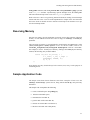
Reserving Memory
2
Note that it is entirely up to the application to properly reserve those portions of physical
memory on each SBC that will be the source or target of read(2) or write(2)
operations.
The reservation of memory is accomplished by modifying the res_sects[] array in the
/e tc /co nf /p ack .d /m m/ spa ce .c f i l e f o r t h e h o s t S B C , a n d / o r t h e
<virtual_rootpath>/etc/conf/pack.d/mm/space.c file for a client SBC.
For example, to reserve 16384 bytes of memory, starting at the 24MB physical memory
location, the following entry would be added:
struct res_sect res_sects[] = {
/* r_start, r_len, r_flags */
{0x1800000, 0x4000, 0};
{0, 0, 0}
};
Note that the last entry should always be the NULL (zero) entry, for the purpose of
terminating the list.
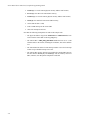
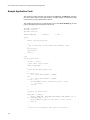
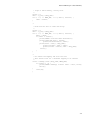
Sample Application Code
2
The sample code shown below illustrates some basic examples of how to use the
read(2) and write(2) system services, along with the ioctl(2) calls previously
mentioned.
This sample code accomplishes the following:
• creates a I/O buffer space using mmap(2),
• locks down the buffer space,
• determines the local SBC id,
• gets the mask of all remote SBC ids,
• chooses one remote SBC to read/write to,
• fills the write buffer with a data pattern,
2-7
Power Hawk Series 600 Closely-Coupled Programming Guide
• lseek(2)s to set the remote physical memory address start location,
• write(2)s the data to the remote SBC memory,
• lseeks(2)s to reset the remote physical memory address start location,
• read(2)s the data back from remote SBC memory,
• verifies that the data is valid,
• sends a VME interrupt to the remote SBC
• closes file descriptors and exits.
Note that the following assumptions are made in this sample code:
2-8
-
The physical address range from 0x1800000 to 0x1803fff has been
reserved on the remote SBC in the res_sect[] array.
-
The remote SBC’s VME_IRQ3_ENABLE tunable has been set to 1, and
all other SBCs in the cluster, including the local SBC, has set this tunable
to 0.
-
The remote SBC has either a kernel interrupt routine or user-level interrupt
routine set up to handle interrupt vector 252.
-
The remote SBC memory has not been modified by another SBC between
the time that the write(2) and read(2) calls are made by this local
SBC; otherwise, the data pattern comparison would fail.
Reading and Writing Remote SBC Memory
Begin Sample Application Code --------------------------------------------------------------------------------------------------------------------------------------------#include
#include
#include
#include
#include
#include
#include
#include
<sys/types.h>
<sys/param.h>
<sys/mman.h>
<sys/sbc.h>
<unistd.h>
<stdio.h>
<fcntl.h>
<errno.h>
/*
* File descriptors.
*/
int local_fd;
int remote_fd;
/* The local SBC */
/* The remote SBC */
/*
* File name buffer.
*/
char filename[MAXPATHLEN];
/*
* Physical address range starts at 24mb for 4 pages.
*/
#define PHYS_START_ADDR
0x1800000
#define BUFFER_SIZE
0x4000
/*
* Starting value for the write buffer.
*/
#define PATTERN_SEED
0x10203040
/*
* The VME level and vector for sending a VME interrupt to the remote SBC.
*/
#define INT_VECTOR
252 /* interrupt vector (0xfc) */
#define VME_LEVEL
3
/* VME level 3 */
/*
* Construct the irq_vector parameter for the SBCIOC_GEN_VME_INTR ioctl(2).
*/
u_short irq_vector = ((VME_LEVEL << 8) | INT_VECTOR);
main(argc, argv)
int argc;
char **argv;
{
int i, status, value, fd;
int local_board_id;
/*
int *bufferp;
/*
int *bp;
/*
int remote_board_id;
/*
u_int remote_board_id_mask;
/*
local SBC id */
mmap(2)ed buffer */
pointer to walk through the buffer */
remote SBC id to read/write */
mask of all remote SBCs in the cluster */
2-9
Power Hawk Series 600 Closely-Coupled Programming Guide
/*
* mmap(2) a zero-filled buffer into the address space.
*/
fd = open(“/dev/zero”, O_RDWR);
if (fd == -1) {
printf(“ERROR: open(2) of /dev/zero failed, errno %d\n”,
errno);
exit(1);
}
bufferp = (int *)mmap((void *)NULL, (size_t)BUFFER_SIZE,
PROT_READ|PROT_WRITE|PROT_EXEC, MAP_PRIVATE, fd, 0);
if (bufferp == (int *)-1) {
printf(“ERROR: mmap(2) failed, errno %d\n”, errno);
exit(1);
}
close(fd);
/*
* Lock down I/O buffer to improve performance.
*/
status = memcntl((caddr_t)bufferp, (size_t)BUFFER_SIZE,
MC_LOCK, 0, 0, 0);
if (status == -1) {
printf(“ERROR: memcntl(2) failed, errno = %d\n”, errno);
exit(1);
}
/*
* Open(2) the host device file, since it is known to exist.
*/
fd = open(“/dev/host”, O_RDWR);
if (fd == -1) {
printf(“ERROR: open(2) of /dev/host failed, errno %d\n”,
errno);
exit(1);
}
/*
* Get our local SBC board id.
*/
status = ioctl(fd, SBCIOC_GET_BOARDID, &local_board_id);
if (status == -1) {
printf(“ERROR: SBCIOC_GET_BOARDID ioctl(2) failed, errno %d\n”,
errno);
exit(1);
}
/*
* Open our local SBC board id.
*/
if (local_board_id) {
close(fd);
sprintf(filename, “/dev/target%d”, local_board_id);
local_fd = open(filename, O_RDWR);
if (local_fd == -1) {
printf(“ERROR: open(2) of %s failed, errno %d\n”,
filename, errno);
2-10
Reading and Writing Remote SBC Memory
exit(1);
}
}
else {
/*
* Local SBC is host, just use existing fd.
*/
local_fd = fd;
}
/*
* Get the mask of remote SBC board ids.
*/
status = ioctl(local_fd, SBCIOC_GET_REMOTE_MASK, &remote_board_id_mask);
if (status == -1) {
printf( “ERROR: SBCIOC_GET_REMOTE_MASK ioctl(2) failed, errno %d\n”,
errno);
exit(1);
}
if (!remote_board_id_mask) {
printf(“ERROR: no remote SBCs found.\n”);
exit(1);
}
/*
* Use the first remote SBC id in the returned id mask.
*/
for (i = 0; remote_board_id_mask; i++) {
if (remote_board_id_mask & 1)
break;
remote_board_id_mask >>= 1;
}
remote_board_id = i;
/*
* Open(2) the remote SBC device file.
*/
if (remote_board_id)
sprintf(filename, “/dev/target%d”, remote_board_id);
else
strcpy(filename, “/dev/host”);
remote_fd = open(filename, O_RDWR);
if (remote_fd == -1) {
printf(“ERROR: remote open(2) of %s failure, errno = %d\n”,
filename, errno);
exit(1);
}
/*
* Fill the write buffer with some known pattern.
*/
for (value = PATTERN_SEED, i = 0, bp = bufferp;
i < (BUFFER_SIZE/4); i += 4, value += 1, bp++)
{
*bp = value;
}
/*
2-11
Power Hawk Series 600 Closely-Coupled Programming Guide
* Seek up to the specified starting location.
*/
status = lseek(remote_fd, PHYS_START_ADDR, SEEK_SET);
if (status == -1) {
printf(“ERROR: lseek() for write failure, errno = %d\n”,
errno);
exit(1);
}
/*
* Write the data to the remote SBC’s memory.
*/
status = write(remote_fd, bufferp, BUFFER_SIZE);
if (status == -1) {
printf(“ERROR: write(2) failure, errno = %d\n”, errno);
exit(1);
}
if (status == 0) {
printf(“ERROR: write(2) returned EOF.\n”);
exit(1);
}
if (status < BUFFER_SIZE) {
printf(“ERROR: write returned only %d bytes\n”, status);
exit(1);
}
/*
* Set the file position back to where we started.
*/
status = lseek(remote_fd, PHYS_START_ADDR, SEEK_SET);
if (status == -1) {
printf(“ERROR: lseek() for read failure, errno = %d\n”, errno);
exit(1);
}
/*
* Now read the data that we just wrote to see that it matches.
*/
status = read(remote_fd, bufferp, BUFFER_SIZE);
if (status == -1) {
printf(“ERROR: read(2) failure, errno = %d\n”, errno);
exit(1);
}
if (status == 0) {
printf(“ERROR: read(2) returned EOF.\n”);
exit(1);
}
if (status < BUFFER_SIZE) {
printf(“ERROR: read returned only %d bytes\n”, status);
exit(1);
}
/*
* Check the data in the read buffer against the values expected.
*/
for (value = PATTERN_SEED, i = 0, bp = (int *)bufferp;
i < (BUFFER_SIZE/4); i += 4, value += 1, bp++)
{
if (*bp != value) {
2-12
Reading and Writing Remote SBC Memory
printf(“ERROR: data mismatch at offset 0x%x.\n”, i);
printf(“
Expected 0x%x, read 0x%x\n”,
value, *bp);
exit(1);
}
}
/*
* Send an interrupt to the remote SBC to let
* it know that new data is available.
*/
status = ioctl(local_fd, SBCIOC_GEN_VME_INTR, irq_vector);
if (status == -1) {
printf(“ERROR: SBCIOC_GEN_VME_INTR ioctl(2) failed, errno %d\n”,
errno);
exit(1);
}
/*
* All done. Close the files.
*/
close(local_fd);
close(remote_fd);
}
-------------------------------------------------------------------------------------
End Sample Application Code.
2-13
Power Hawk Series 600 Closely-Coupled Programming Guide
2-14
3
Chapter 3Shared Memory
3
3
3
Overview
3
SBCs within the same cluster can be configured to share memory with each other. There
are two methods for configuring and accessing shared memory in a closely-coupled system (CCS):
• Slave MMAP
• Master MMAP (See Note)
Both the Slave MMAP method and the Master MMAP method for accessing shared memory may be used on the same system.
These methods of memory access provide the fastest and most efficient method of reading
and writing small amounts of data between two SBCs.
Note
An alternative shared memory access method, Master MMAP
Type 1 (MMAP/1), is described in Appendix A.
Slave MMAP Shared Memory Overview
3
The Slave MMAP interface allows simultaneous access to physical memory (DRAM) on
every SBC in a cluster. The local processor defines a shared memory segment which is
slave mapped into a well known VME A32 address range.
Implementation:
-
The SBC driver is responsible for opening a VME A32 window at a
“well known” VME A32 address into which it maps its shared
DRAM memory.
-
Uses the “VMEbus Slave Image 3” registers in the Tundra Universe
PCI bus to VMEbus bridge.
-
Remote SBCs access this mapped DRAM through this VME slave
window.
3-1
Power Hawk Series 600 Closely-Coupled Programming Guide
Advantages:
-
Simultaneous access to all other SBCs which define a Slave MMAP
memory region.
-
No need to know the physical DRAM address of any of the remote
memory regions in order to access them.
-
No need to reconfigure existing clients when adding additional SBCs
to an existing configuration.
-
Supports both mmap(2) and shmbind(2) shared memory
interfaces.
-
Shared memory may be either dynamically allocated or statically
allocated (by defining a res_sects[] in the MM driver's space.c).
Disadvantages:
-
Only one contiguous shared memory region is configurable per SBC.
-
May consume more VME A32 space than is actually required.
The amount of physical memory that can be mapped on any one SBC
is limited to 8384512 bytes (8MB minus 4KB).
Master MMAP Shared Memory Overview
3
The Slave shared memory method is designed to access portions of remote SBC DRAM.
This means that access to this type of remote memory is only possible if the SBC defining
the shared memory area was found to be present in the system.
The Master MMAP method need not be tied to SBC DRAM. This interface defines a static
mapping that is performed during system initialization which maps the desired local processor bus address range into any VME A32 address space, which the mapping processor
has not already mapped with a VME slave window, DRAM map window, or ISA Register
window.
Implementation:
-
Uses the “PCI Slave Image 0” registers in the Tundra Universe PCI
bus to VMEbus bridge. This allows for the local processor to
generate “master” mode accesses on the VMEbus.
-
Static mapping performed at system initialization.
Advantages:
3-2
-
Supports both mmap(2) and shmbind(2) shared memory
interfaces.
-
Supports largest shared memory segments (over 1GB).
Shared Memory
-
Shared memory does not have to reside on a SBC. It could be on a
VMEbus memory module, et al.
-
Programmable VMEbus A32 address translation capability.
Mapping is established during system initialization.
Disadvantages:
-
Only one contiguous shared memory region configurable per
SBC. However, each SBC may map to a different VME memory
range.
-
Local memory cannot be accessed through this interface.
Accessing Shared SBC Memory
3
Using read(2) and write(2) to Access Shared SBC Memory
3
The read(2) and write(2) system service calls are available to examine and modify another SBC's local DRAM memory. A highly efficient VME A32/D64 block mode
transfer mode is used when buffers are properly aligned on 64 bit boundaries.
Using mmap(2) To Access Shared SBC Memory
3
The mmap(2) system service call can be used to access all types of closely-coupled
shared memory. The mmap(2) interface allows processes to directly map both local
and remote closely-coupled shared memory into it's own address space for normal load
and store operations.
Using shmbind(2) To Access Shared SBC Memory
3
The shmbind(2) system service can be used to access both types of closely-coupled
Slave MMAP and Master MMAP shared memory.
Shmbind(2) may always be used to access a remote SBC's Slave MMap shared
memory, regardless of whether that remote shared memory area was dynamically or
statically allocated. However, when an application is accessing the local SBC's Slave
MMap shared memory area, the shared memory area MUST be statically allocated and
reserved.
3-3
Power Hawk Series 600 Closely-Coupled Programming Guide
Closely-Coupled Shared Memory Limitations
The following limitations exist for all closely-coupled shared memory methods:
• The test and set type of instructions are not supported on remote shared
memory through either the mmap(2) or shmbind(2) memory. (However, any such mapping to a processor’s local memory may use the
following system calls.) The following features make use of test and
set functionality and therefore, cannot be used in remote SBC memory:
•
_Test_and_Set(3C) - the test and set intrinsic
• sem_init(3) - the family of POSIX counting semaphore
primitives
• synch(3synch) - the families of Threads Library synchronization
primitives including _spin_init, mutex_init,
rmutex_init,
rwlock_init,
sema_init,
barrier_init and cond_init
• spin_init(2) - the family of spin lock macros
• Remote master access requests coming in from the VMEbus into SBC
DRAM memory are made possible by proper setup of one of the VMEbus
Slave Image registers. When a reset is issued to an SBC, the VMEbus
Slave Image registers performing the mapping are disabled and are not reenabled until some time later. When using the Master MMAP shared memory, the slave register mapping DRAM to the VMEbus is not enabled until
the PPCbug code can initialize it. When using Slave MMAP shared memory, the slave register mapping the physical shared memory is initialized by
PowerMAX OS, and is thus not available until a new kernel is downloaded
and started on the board which was reset.
During this time interval, memory accesses from applications (local
processes) accessing remote mmap(2) memory (or remote shmbind(2)
accesses to Slave MMAP memory) cannot be resolved.
The IGNORE_BUS_TIMEOUTS tunable (enabled by default in closelycoupled configurations) should be kept enabled in order to prevent a
machine check panic or a system fault panic from occurring on the system
that is issuing the remote memory request.
With the IGNORE_BUS_TIMEOUTS tunable enabled, the application
will not receive any notification that these reads and/or writes are not
completing successfully. However, writes to the remote DRAM memory
will not actually take place, and the reads from the remote DRAM memory
will return values of all ones. For example, word reads will return values of
0xFFFFFFFF. Once the remote SBC environment has been re-initialized
by PPCBUG, the remote DRAM memory reads and writes will once again
operate normally.
If the IGNORE_BUS_TIMEOUTS tunable is not enabled, a system panic
will then occur. Therefore, it is recommended that the tunable
IGNORE_BUS_TIMEOUTS be enabled; otherwise, applications that are
3-4
3
Shared Memory
known to be actively accessing the memory on a remote SBC should be
stopped before that remote SBC is reset, or rebooted via sbcboot(1M).
Slave Shared Memory (SMAP)
3
The slave shared memory interface (SMAP) provides an interface which supports
simultaneous access to physical memory (DRAM) on every SBC in a cluster.
The SMAP interface provides shared access to local DRAM by mapping it's DRAM
addresses into a pre-configured VME A32 address range. Other SBCs in the cluster access
such memory by attaching to the VME A32 addresses using either the mmap(2) or
shmbind(2) system call interfaces.
SMAP User Interface
3
SMAP mmap(2) system call interface
3
Access to SMAP shared memory is obtained by opening the /dev/host and/or
/dev/target[n] device files, followed by an mmap(2) call, using the file descriptor
that was returned from the open(2) call.
When accessing SMAP shared memory, opening the device file associated with the local
SBC results in mmap(2) access to local DRAM. If the device file opened and
subsequently mmap'ed refers to a remote SBC, then access to the remote SBC's DRAM
will be performed over the VMEbus. For example, if SBC1 opens /dev/target1, and
mmaps memory using the /dev/target1 file descriptor, the mapped memory directly
accesses local DRAM. This DRAM is visible to any other SBC in the cluster when they
open /dev/target1. The only difference is that the remote SBC accesses to this
DRAM will be made over the VMEbus.
If SBC1 now opens /dev/host, SBC1 will be able to access memory on SBC0 (the
host) over the VMEbus. Additionally, SBC1 could also open /dev/target2 and gain
access to SBC2's shared memory area.
All three memory area's in this example can be accessed at the same time.
When issuing a mmap(2) system call, the “off” parameter that is specified is relative to
the starting physical address that is mapped by the local or remote client.
SMAP shmbind(2) system call interface
3
The shmbind(2) system call interface can be used to access all remote SBCs slave
shared memory. However, if it becomes necessary to shmbind(2) to on-board DRAM,
you must allocate the slave shared memory using the res_sects[] array (memory
cannot be dynamically allocated). Furthermore, when shmbind(2)ing to this memory,
the DRAM address must be used (as defined in res_sects[]). Do not attempt to
3-5
Power Hawk Series 600 Closely-Coupled Programming Guide
shmbind(2) to local memory through the VME window address. This may result in a
system bus and/or VMEbus hang.
SMAP Limitations and Considerations
3
• The SMAP shared memory is mapped into VME A32 space by the SBC
driver module during system initialization. This means that this memory
area should only be accessed while the remote SBC is up.
• The maximum amount of SMAP shared memory that can be mapped is
8384512 bytes (8MB minus 4KB).
SMAP Kernel Configuration
3
SMAP Kernel Tunables
3
The slave shared memory interface is implemented using the “VMEbus Slave Image 3”
(VSI3) registers on the Tundra Universe chip (the SBC's VMEbus bridge). The VSI3
provides VMEbus to PCI bus translation. The system software understands this and
performs the proper PCI bus to Processor bus offset conversions based on the Slave
Shared Memory tunables.
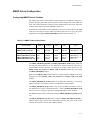
The slave shared memory area is configured using the vmebootconfig(1M) utility.
The tunables VME_SLV_WINDOW_BASE and VME_SLV_WINDOW_SIZE are
configurable via entries in the /etc/dtables/clusters.vmeboot table. This table
Table 3-1. SMAP Kernel Tunables
Kernel Tunable
Module
Default
Min.
Max.
Unit
PH620_VME_A32_START
PH620_VME_A32_END
vme
vme
0xC000
0xFAFF
0xA000
0xA000
0xF000
0xFCAF
VME Address>>16
VME Address>>16
VME_SLV_WINDOW_BASE
VME_SLV_WINDOW_SIZE
vme
vme
0xF000
1
0xA000
1
0xFAFE
128
VME Address>>16
in 64KB units
SBC_SLAVE_MMAP_SIZE
SBC_SLAVE_DMAP_START
sbc
sbc
0
0
0
0
2047
0x3FFF
in 4KB units
Local Addr>>16
is processed by the vmebootconfig(1M) utility. The other tunables listed in
Table 3-1 above may be set using the config(1M) utility and specifying the clients
virtual root directory using the -r option.
VME_SLV_WINDOW_BASE specifies the upper 16 bits of the start of the VME A32
space where single board computers (SBC) enable a slave window which allow other
SBCs to access a region of this computer’s memory (DRAM). This window is shared
between kernel dedicated functions and the user accessible Slave MMAP area. The slave
3-6
Shared Memory
map area on the VMEbus must be configured in the VME A32 master window (as defined
by the tunables PH620_VME_A32_START and PH620_VME_A32_END).
VME_SLV_WINDOW_SIZE specified the maximum amount of DRAM which can be
mapped by each SBC in a cluster. The kernel reserves the first 4096 bytes for it's own use.
This 4KB area is referred to as the DMAP area. The remaining bytes can be used as a
slave mappable area. This user accessible portion is referred to as the SMAP area.
The window size is specified in units of 64KB. For example, a value of 2 indicates that the
maximum window size per SBC is 128KB (2*64KB).
NOTE
VME_SLV_WINDOW_SIZE is a maximum value; not all
SBCs actually have to dedicate DRAM to this entire region. The
actual amount of DRAM mapped onto the VMEbus is defined by
the tunable SBC_SLAVE_MMAP_SIZE. However, all SBCs in
a cluster must define the same value for
VME_SLV_WINDOW_SIZE.
The actual VMEbus address range mapped is based on the computer's board identification
and can be calculated as follows:
ulong_t sw_base; /* the effective VME address of base */
ulong_t sw_size; /* the maximum number of bytes to map */
ulong_t sw_addr; /* the vme address of this SBC's window */
sw_base = VME_SLV_WINDOW_BASE << 16;
sw_size = VME_SLV_WINDOW_SIZE * 64*1024;
sw_addr = sw_base + (board_id * sw_size)
Conceptually, an array of “sw_size” size windows are defined in VME A32 space. The
start of the array is “sw_base”. The board number [0,1,..,20] is used as an index into the
array to find the specified board's slave window area. The “sw_addr” is the actual VME
A32 address mapped by the SBC. Since the entire slave window array resides within VME
A32 address es acces si ble via t he s tandard mast er map (as defined by the
PH620_VME_A32_START and PH620_VME_A32_END tunables), all slave window
memory is accessible simultaneously by any process on any board.
F o r a n i n d i v i d u a l b o a r d t o c o n f i g u r e S M A P s h a r e d m e m o r y, t h e
SBC_SLAVE_MMAP_SIZE must be non-zero. A value of zero means that, for this
SBC, no user accessible shared memory is to be mapped (although the 4KB kernel window is still mapped, no additional DRAM will be allocated or used for the user shared
memory region).
The SBC_SLAVE_DMAP_START tunable is used to specify if the physical DRAM
used in the slave window mapping is dynamically allocated, or uses reserved system
memory (as defined in the res_sects[] array in <virtual_rootpath>
/etc/conf/pack.d/mm/space.c).
If SBC_SLAVE_DMAP_START is zero, then slave window DRAM is dynamically
allocated during system initialization. This is the preferred configuration unless the
3-7
Power Hawk Series 600 Closely-Coupled Programming Guide
particular application requires shmbind(2) support for accessing this Slave area from
the local SBC.
If SBC_SLAVE_DMAP_START is non-zero, then the SBC driver will attempt to use
reserved memory that must also be defined in the res_sects[] array. In order for
reserved memory to be used, the SBC driver will search the res_sects[] array and try
to locate an entry that starts at the address specified by SBC_SLAVE_DMAP_START
multiplied by 64KB.
For example, if SBC_SLAVE_DMAP_START is set to 0x0100, then a res_sects[]
entry must be defined to reserve 4KB of memory starting at 0x01000000 in physical
DRAM for the area required by the kernel. The res_sect[] entry for this example
would look like the following:
res_sect res_sects[] = {
/* r_start,
r_len, r_flags */
{ 0x01000000, 0x1000, 0 }, /*kernel required area */
{ 0, 0, 0} /* this must be the last line */
}
Note that the above example will only succeed if SBC_SLAVE_MMAP_SIZE was
configured to zero (i.e. no user slave shared memory segment defined).
To configure a reserved memory section with user accessible slave shared memory
support, an ADDITIONAL res_sect[] array entry must be made that starts
immediately AFTER the 4KB kernel definition and has a length (r_len) that is AT
LEAST the size defined by SBC_SLAVE_MMAP_SIZE. For example, assume that in
the previous example, the user wants to add a 256KB shared memory area. The
res_sects[] array would look like:
res_sect res_sects[] = {
/* r_start,
r_len, r_flags */
{ 0x01000000, 0x1000, 0 }, /* kernel required area */
{ 0x01001000, 0x40000, 0 }, /* user accessible area */
{ 0, 0, 0} /* this must be the last line */
}
In the example above, assume that this represents the largest SMAP shared memory
region that will be defined in the system (i.e. all SBC's in the cluster will be configured to
have 256KB of user accessible SMAP slave shared memory OR LESS).
For this SBC, define a user accessible slave shared memory area of 262144 (0x40000)
bytes. Since the kernel also requires a 4KB area, the total amount of DRAM which needs
to be mapped to the VMEbus is 266240 (0x41000) bytes. VME_SLV_WINDOW_SIZE
needs to be defined in multiples of 64KB, so the total DRAM size needs to be rounded up
to a 64KB boundary in order to calculate the VME_SLV_WINDOW_SIZE tunable
value. Rounding 0x41000 up to a 64KB boundary yields a slave window size of 0x50000.
VME_SLV_WINDOW_SIZE is defined to be a number of 64KB segments. It is
necessary to divide the byte count by 64KB (0x10000) to arrive at the
VME_SLV_WINDOW_SIZE tunable value 5 (i.e. 0x50000 / 0x10000).
3-8
Shared Memory
NOTE
W h e n c o n f i g u r i n g V M E _ S LV _ W I N D O W _ B A S E a n d
VME_SLV_WINDOW_SIZE, assure that the range of VME
addresses defined by these tunables lay within the VME addresses
d e f i n e d b y t h e P H 6 2 0 _ V M E _ A 3 2 _ S TA RT a n d
PH620_VME_A32_END tunables.
It is necessary to let VME_SLV_WINDOW_BASE default to 0xF000 which equates to
VME A32 address 0xF0000000. Each SBC in the system will map at least a 4KB area at
some offset from this base address.
The VME_SLV_WINDOW_SIZE is set to 5, which defines a window size of 327680
(0x50000) bytes (5*64*1024). This means that SBC0 will map it's slave window at
0xF0000000, SBC1 at 0xF0050000, SBC2 at 0xF00A0000, and so on. This will be the
case on all SBC's, regardless of the amount of slave shared memory that is actually
mapped. For example, SBC2 may define SBC_SLAVE_MMAP_SIZE to be zero.
NOTE
Even though a SBC may not map or even access the SMAP
shared memory area, all SBC in the cluster must be configured
w i t h t h e s a m e V M E _ S LV _ W I N D O W _ B A S E a n d
VME_SLV_WINDOW_SIZE values. VMEbus networking will
not work if these values differ between SBC's in the same cluster
and may result in a cluster hang during system initialization.
To complete the reserved memory configuration:
VME_SLV_WINDOW_BASE
0xF000
/* base address starts at 0xF0000000 */
VME_SLV_WINDOW_SIZE
5
/* 5*(64*1024) = 0x50000 bytes */
SBC_SLAVE_MMAP_SIZE
64
/* 64*(4*1024) = 0x40000 bytes */
SBC_SLAVE_DMAP_START
0x0100
/* r_start = 0x01000000 */
As stated earlier, VME_SLV_WINDOW_BASE and VME_SLV_WINDOW_SIZE
m u s t b e d e f in e d to b e t h e s a m e v a lu e s a c r o s s a ll S BC ' s in a c lu s te r. T h e
SBC_SLAVE_MMAP_SIZE and SBC_SLAVE_DMAP_START values may differ
between SBC's as long as SBC_SLAVE_MMAP_SIZE does not define an area larger
that can be accommodated by VME_SLV_WINDOW_SIZE.
SMAP /dev/host and /dev/target[n] device files
3
The /dev/host and /dev/target[n] device files are an integral component to a
closely-coupled system. These files should exist for each SBC in the system.
In the event that any of these devices have not been created, they can be manually created
by issuing the following to create the device files:
3-9
Power Hawk Series 600 Closely-Coupled Programming Guide
/etc/conf/bin/idmknod [-o <virtual_rootpath>/dev]
[-r <virtual_root>/etc/conf] -M sbc
Master MMAP Shared Memory (MMAP)
\
3
The Master MMAP (MMAP) interface allows access to “any” single, contiguous VME
A32 address range that is not already mapped as a VME A32 slave on the current board.
SBCs contain a Tundra Universe Bridge that implements a “PCI Slave Image 0” (LSI0)
register set which may be configured by the system administrator to map in the remote
DRAM memory of another SBC that is located in the same VME chassis using the
PH620_SBCMMAP tunables.
Both the mmap(2) and shmbind(2) methods for accessing shared memory regions are
supported.
MMAP User Interface
3
MMAP mmap(2) system call interface
3
The remote mapping is created by opening the /dev/sbcmem0 device file, followed by
an mmap(2) call, using the file descriptor that was returned from the open(2) call.
The /dev/sbcmem0 device is auto-configured during system initialization to allow
mmap(2) access to the MMAP shared memory region.
The “off” parameter that is specified on an mmap(2) call is relative to the starting
physical address attribute that is associated with the /dev/sbcmem0 file. For example, a
value of zero for the mmap(2) “off” parameter will map in the first page of the VME A32
address range that has been configured.
MMAP shmbind(2) system call interface
3
The Tundra Universe LSI0 registers are fully initialized during system initialization.
Therefore, the shmbind(2) method for accessing shared memory is supported.
MMAP Limitations and Considerations
• The /dev/host and /dev/target[1-20] device files must not be
used to mmap(2) Master MMAP shared memory as these devices are used
to access the Slave MMAP type of closely-coupled shared memory. The
/dev/sbcmem0 device file must be used for this purpose.
• Other /dev/sbcmem[1..n] files are not configured and should not be
used.
3-10
3
Shared Memory
MMAP Kernel Configuration
3
Configuring MMAP Kernel Tunables
3
The Tundra Universe's PCI Slave Image 0 (LSI0) registers are configured by the sbc kernel driver during system initialization to provide a master window into remote VME A32
space. This window should not overlap any of the VMEbus Slave (VSI0, VSI1, and VSI3)
windows which map local processor DRAM to VME A32.
By default, this VME window is not configured for use by the sbc kernel driver. The VME
window for accessing the remote VME A32 address space can be set up by the system
administrator by modifying PH620_SBCMMAP tunables defined in Table 3-2.
Table 3-2. MMAP Tunable Default Values
Kernel Tunable
Module
Default
Min.
Max.
Unit
PH620_VME_A32_START
PH620_VME_A32_END
vme
vme
0xC000
0xFAFF
0xA000
0xA000
0xF000
0xFCAF
VME Address>>16
VME Address>>16
PH620_SBCMMAP_TYPE
PH620_SBCMMAP_START
PH620_SBCMMAP_END
PH620_SBCMMAP_XLATE
vme
vme
vme
vme
0
0xFB00
0xFCAF
0x0000
0
0xA000
0xA000
0x0000
2
0xFCAF
0xFCAF
0xFFFF
Must set to 2
VME Address>>16
VME Address>>16
Offset>>16
The PH620_SBCMMAP_START and PH620_SBCMMAP_END tunables define the
starting and ending addresses of the VME space window and must fall between
0xA0000000 and 0xFCAFFFFF. In addition, the VME window defined by the
PH620_VME_A32_START and PH620_VME_A32_END tunables must not overlap
the PH620_SBCMMAP window.
Space from the PH620_VME_A32 window may be taken for Master MMAP use by modifying that window's PH620_VME_A32_START and/or PH620_VME_A32_END
tunables.
The PH620_SBCMMAP_START tunable is in 64KB units (0x10000), so a starting
address of 0xC012, for example, represents a VME address of 0xC0120000.
The PH620_SBCMMAP_END tunable is also in units of 64KB, but with the lower 16
bits implicitly set to a value of 0xFFFF. Therefore, a value for PH620_SBCMMAP_END
such as 0xC112, for example, represents an ending VME address of 0xC112FFFF.
The MMAP VME window is enabled by setting the PH620_SBCMMAP_TYPE tunable
to 2.
The PH620_SBCMMAP_XLATE value is added to PH620_SBCMMAP_START to
form the effective upper 16 bits of the VME address generated. The lower 16 bits on the
local bus drive the lower 16 bits of the VMEbus address.
3-11
Power Hawk Series 600 Closely-Coupled Programming Guide
When setting up and enabling the MMAP window, be certain that this window does not
overlap with the other VME A32 window that is used for normal A32 VME I/O device
related accesses.
Configuring /dev/sbcmem0 File
3
The /dev/sbcmem0 file needs to be created. This is accomplished by un-commenting
sbcmem0
or
adding
the
appropriate
line
in
the
file
<virtual_rootpath>/etc/conf/node.d/sbc. After the line has been added or
uncommented, the system administrator can issue the following to create the device file:
/etc/conf/bin/idmknod [-o <virtual_rootpath>/dev]
[-r <virtual_rootpath>/etc/conf] -M sbc
As an example, the following lines would appear in the /etc/conf/node.d/sbc file:
#Devic
e
#Drive
r
sbc
#sbc
#sbc
#sbc
Node
Node
Name
Type
sb c me m
c
0
c
sb c me m
c
1
c
sb c me m
2
sb c me m
3
Minor
Number
100
101
102
103
User
ID
0
0
0
0
Group
ID
3
3
3
3
Perms
640
640
640
640
Security
Level
1
1
1
1
Note that /dev/sbcmem[1..n] are commented out since they are not used with
MMAP memory mapping.
3-12
4
Chapter 4Inter-SBC Synchronization and Coordination
4
4
4
Overview
4
Several mechanisms exist for processes on different SBCs to synchronize and coordinate
their activities. This chapter will discuss four:
• Interrupt generation and notification. This method would primarily be
used by a process to “signal” a process on a specific SBC.
• Remote message queues. Used to transfer data between processes located
on any SBC within the cluster. The full functionality of POSIX message
queues is provided.
• Remote semaphores. Used to synchronize the activities of processes
located on any SBC within the cluster. The full functionality of POSIX
semaphores is provided.
• CCS_FBS. Provides cluster-wide synchronization for all FBS schedulers
that are attached to the same Closely Coupled timing device.
• RCIM Coupled FBS. While not specific to closely-coupled systems,
RCIM Coupled FBS timing devices may used by SBCs within a single
cluster for achieving cluster-wide synchronization for all FBS schedulers
that are attached to the same RCIM Coupled timing device. Additionally,
RCIM Coupled timing devices may also be attached to by FBS schedulers
on SBCs where one or more of those SBCs may reside outside of the
cluster.
Inter-SBC Interrupt Generation and Notification
4
Program interfaces are available via ioctl(2) commands to interrupt SBCs within the
same cluster in a closely-coupled system (CCS).
Processes with the appropriate privilege (P_USERINT) may interrupt an arbitrary SBC
and/or receive a notification when an interrupt is received. (For information on privileges,
refer to the intro(2) and privilege(5) system manual pages, and the “Administering Privilege” Chapter in the System Administration (Volume 1) manual).
Associated with each inter-SBC interrupt is a “virtual interrupt” id, which ranges from 0 to
127. The effect is that there are 128 virtual interrupts available to these ioctl commands.
4-1
Power Hawk Series 600 Closely-Coupled Programming Guide
The ioctl commands are applied to the SBC device files, i.e. /dev/host or
/dev/targetn (where n = 1 to 20).
Interrupt generation is done by specifying an SBC that will receive the interrupt in
addition to a virtual interrupt id. The SBC that will receive the interrupt must be within the
same cluster as the sending SBC. An interrupt may also be sent to the local SBC.
Interrupt notification is done by specifying the virtual interrupt id as well as the
notification type. Notification will occur whenever the indicated virtual interrupt is
received on the local SBC (regardless of originating SBC).
Interrupt notification may be done by either signal or user-level interrupt. The signal
number or interrupt vector number must be specified. The caller is responsible for establishing the disposition of the signal handler or user-level interrupt routine.
Interrupt notification may be either permanent or temporary. A permanent notification
remains until explicitly removed. A temporary notification is removed when a virtual
interrupt (indicated id) is received.
Only one notification type is allowed per virtual interrupt.
Calling Syntax
4
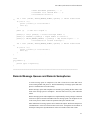
The calling syntaxes for interrupt generation, signal notification and interrupt notification
are shown below.
Interrupt Generation
#include <sys/sbc.h>
ioctl(fildes, SBCIOC_MBINTR_GEN, parms);
int fildes, command, *parms;
struct parms {
int
virtual_interrupt_id;
};
Generates a virtual interrupt on the SBC specified by fildes. fildes is a file descriptor
obtained by having previously opened /dev/host or /dev/targetn. fildes determines which SBC a generated interrupt will be directed to. The receiving SBC must be
within the same cluster as the sending SBC. The virtual interrupt number is specified by
virtual_interrupt_id.
virtual_interrupt_id is a number between 0-127.
Returns:
0
4-2
: successful
ENXIO: sbc module not configured.
ENODEV: sbc device not present or not CCS system.
EINVAL: virtual_interrupt_id is out of range (0-127).
EHOSTDOWN: specified sbc is not available.
ENOLINK: communication failure.
Inter-SBC Synchronization and Coordination
EPERM: caller does not have P_USERINT privilege.
EFAULT: illegal address for parmsSignal Notification
#include <sys/sbc.h>
ioctl(fildes, SBCIOC_MBINTR_SIGNAL, parms);
int fildes, command, *parms;
struct parms {
int
virtual_interrupt_id;
int
signo;
int
op;
};
Attaches (or detaches) signal notification for the calling process when a virtual interrupt
with the specified id is delivered to local SBC.
fildes is a file descriptor obtained by opening /dev/host or /dev/targetn. The specific SBC associated with this file descriptor is not significant as notification is always
delivered to the calling process.
virtual_interrupt_id is a number between 0-127. signo is the signal number to be used for
process notification.
op is one of:
SBCIOC_MBINTR_ATTACH
-orSBCIOC_MBINTR_DETACH
plus the following flag may also be Or’d in:
SBCIOC_MBINTR_PERM
The operation SBCIOC_MBINTR_ATTACH attaches signal notification to the specified
virtual_ interrupt_ id. If the flag SBCIOC_MBINTR_PERM is set, then the attachment is
permanent and is only removed by an explicit SBCIOC_MBINTR_DETACH. If the flag
SBCIOC_MBINTR_PERM is NOT set, then the attachment is temporary and is removed
when a virtual interrupt at this id occurs (or is explicitly detached).
The operation SBCIOC_MBINTR_DETACH removes a signal notification.
Returns:
0
: successful
ENXIO: sbc module not configured.
ENODEV: sbc device not present or not CCS system.
EINVAL: virtual_interrupt_id is out of range (0-127).
EINVAL: illegal signal number.
EPERM: caller does not have P_USERINT privilege.
EBUSY: interrupt notification already present for this virtual interrupt
(SBCIOC_MBINTR_ATTACH)
ESRCH: no interrupt notification for this virtual interrupt
(SBCIOC_MBINTR_DETACH).
EFAULT: illegal address for parms.
4-3
Power Hawk Series 600 Closely-Coupled Programming Guide
Interrupt Notification
#include <sys/sbc.h>
ioctl(fildes, SBCIOC_MBINTR_UI, parms);
int fildes, command, *parms;
struct parms {
int
virtual_interrupt_id;
int
vector;
int
op;
};
Attaches (or detaches) user-level interrupt notification when a virtual interrupt with the
specified id is delivered to local SBC.
fildes is a file descriptor obtained by opening /dev/host or /dev/targetn. The specific SBC associated with this file descriptor is not significant as notification is always
delivered to the SBC on which the calling process is executing.
virtual_interrupt_id is a number between 0-127. vector is the interrupt vector number of
the user-level interrupt to invoke.
op is one of:
SBCIOC_MBINTR_ATTACH
-orSBCIOC_MBINTR_DETACH
plus the following flag may also be Or’d in:
SBCIOC_MBINTR_PERM
The operation SBCIOC_MBINTR_ATTACH attaches user-level interrupt notification to
the specified virtual_interrupt_id. If the flag SBCIOC_MBINTR_PERM is set, then the
attachment is permanent and is only removed by an explicit.
SBCIOC_MBINTR_DETACH. If the flag SBCIOC_MBINTR_PERM is NOT set, then
the attachment is temporary and is removed when a virtual interrupt at this id occurs (or is
explicitly detached).
The standard initialization required for user-level interrupts (i.e. iconnect(3C) and
ienable(3C)), must still be done.
Note that the calling process may not necessarily be the same process that will receive the
user-level interrupt. The user-level interrupt is delivered to the process which is connected
to the interrupt vector.
For more information on user-level interrupts, refer to the “User-Level Interrupt Routines”
Chapter in the PowerMAX OS Real-Time Guide.
The operation SBCIOC_MBINTR_DETACH removes a user-level interrupt notification.
Returns:
0
4-4
: successful
ENXIO: sbc module not configured.
Inter-SBC Synchronization and Coordination
ENODEV: sbc device not present or not CCS system.
EINVAL: virtual_interrupt_id is out of range (0-127).
EPERM: caller does not have P_USERINT privilege.
EBUSY: interrupt notification already present for this virtual interrupt
(SBCIOC_MBINTR_ATTACH)
ESRCH: no interrupt notification for this virtual interrupt
(SBCIOC_MBINTR_DETACH).
EFAULT: illegal address for parms.
Example Send/Receive Inter-SBC interrupts Programs:
The following are two simple programs that demonstrate how to send and receive interSBC interrupts.
The first program sends the interrupt:
#include
#include
#include
#include
#include
#include
#include
<stdio.h>
<sys/types.h>
<sys/iconnect.h>
<sys/mman.h>
<sys/sbc.h>
<sys/stat.h>
<fcntl.h>
/*
** send virtual interrupt to an SBC
*/
main()
{
int ret;
/* return values */
charfname[100];/* device file name */
int fileds;
/* device file descriptor */
int vid;
/* virtual interrupt number */
int sbcid;
/* SBC number */
printf (“sbc id:”);/* ask operator for SBC number */
scanf (“%d”, &sbcid);/* read in SBC number */
sprintf (fname, “/dev/target%1d”, sbcid); /* build device file name ... */
/* format: /dev/targetn, n = SBC id */
printf (“vid: “);/* ask operator for virtual interrupt ... */
/* number. vids are between 0..127 */
scanf (“%d”, &vid);/* read in virtual interrupt number */
fileds = open (fname, O_RDWR);/* open device file of SBC to direct ... */
/* virtual interrupt to */
if (fileds == -1) {
perror (“open”);/* open failed */
exit (1);
}
4-5
Power Hawk Series 600 Closely-Coupled Programming Guide
ret = ioctl (fileds, SBCIOC_MBINTR_GEN, &vid);
/* send virtual interrupt
*/
if (ret == -1) {
perror (“ioctl”);/* ioctl failed */
exit (1);
}
}
-------------------------------------------------------------------------The second program receives the interrupt:
#include
#include
#include
#include
#include
#include
#include
#include
<stdio.h>
<sys/types.h>
<sys/iconnect.h>
<sys/mman.h>
<sys/sbc.h>
<sys/stat.h>
<signal.h>
<fcntl.h>
/*
** attach signal notification to virtual interrupt
*/
main()
{
int ret;
/* return values */
charfname[100];/* device file name */
int fileds;
/* device file descriptor */
int vid;
/* virtual interrupt number */
int parms[3];/* parameter list */
externvoid sig_handler();
sprintf (fname, “/dev/host”);/* build device file name ... */
/* can use any SBC device file: */
/* /dev/host or /dev/targetn */
printf (“vid: “);/* ask operator for virtual interrupt ... */
/* number. vids are between 0..127 */
scanf (“%d”, &vid);/* read in virtual interrupt number */
fileds = open (fname, O_RDWR);/* open device file */
if (fileds == -1) {
perror (“open”);/* open failed */
exit (1);
}
signal (SIGUSR1, sig_handler);/* establish signal handler */
parms[0] = vid;/* parms[0] = virtual interrupt number */
parms[1] = SIGUSR1;/* parms[1] = signal number to receive */
parms[2] = SBCIOC_MBINTR_ATTACH; /* parms[2] = cmd, attach signal ... */
/* notification to virtual interrupt */
parms[2] |= SBCIOC_MBINTR_PERM;/* parms[2] or-in additional flag ... */
4-6
Inter-SBC Synchronization and Coordination
/* make attachment permanent, ... */
/* otherwise it is removed when ... */
/* notification arrives */
ret = ioctl (fileds, SBCIOC_MBINTR_SIGNAL, &parms); /* attach notification
*/
if (ret == -1) {
perror (“ioctl”);/* ioctl failed */
exit (1);
}
pause ();
/* wait for a signal */
parms[0] = vid;/* parms[0] = virtual interrupt number */
parms[1] = SIGUSR1;/* parms[1] = signal number to receive */
parms[2] = SBCIOC_MBINTR_DETACH; /* parms[2] = cmd, detach signal ... */
/* notification to virtual interrupt */
ret = ioctl (fileds, SBCIOC_MBINTR_SIGNAL, &parms); /* detach notification
*/
if (ret == -1) {
perror (“ioctl”);/* ioctl failed */
exit (1);
}
}
void
sig_handler ()
{
printf (“got a signal\n”);
}
===========================================================================
Remote Message Queues and Remote Semaphores
4
A remote message queue or semaphore is one that is located on a remote SBC and is
accessed using an RPC-like protocol. The full functionality of message queues and semaphores is available when accessed remotely.
Remote message queues and semaphores are named by pre-pending the host name to the
name of the message queue or semaphore. The host name can be any SBC within the
cluster.
Remote message queues and semaphores are implemented by having a unique connection
with a server process located on the SBC where the message queue is at. Requests are sent
to the server process which executes the operation and replies with the result.
More information on message queues can be found in the chapter “Real-Time Interprocess
Communication” in the PowerMAX OS Real-Time Guide. Semaphores are described in
the chapter “Interprocess Synchronization” in the PowerMAX OS Real-Time Guide.
4-7
Power Hawk Series 600 Closely-Coupled Programming Guide
The daemon sbc_msgd(3) is responsible for performing remote server operations.
While this daemon will automatically start on the server SBC without any system
configuration changes, this daemon must be configured to be automatically started on
each client SBC within a closely-coupled cluster by enabling the CCS_IPC subsystem.
Refer to the sbc_msgd(3) man page for more information on sbc_msgd, and see the
vmebootconfig(1M) man page for more information on enabling the CCS_IPC
subsystem.
Coupled Frequency-Based Schedulers
4
The Coupled Frequency Based Scheduler (FBS) support provides two types of timing
devices: Closely Coupled and RCIM Coupled timing devices. Both of these timing
devices may be used to provide cluster-wide synchronization for all FBS schedulers that
are attached to the same Coupled FBS timing device. In addition, RCIM Coupled timing
devices may be used to coupled together FBS schedulers on SBCS that may reside both
within and outside a given closely-coupled cluster.
A Coupled FBS timing device may be attached to a scheduler by making use of the same
library function calls or rtcp commands that are used to attach other types of timing
devices. However, a Coupled FBS timing device must first be "registered" as a Coupled
FBS timing device on the host/SBC where the device interrupt originates, before it may be
attached to FBS schedulers on the local and/or remote hosts/SBCs. Note that only one
FBS scheduler on each host/SBC may be attached to the same Coupled FBS timing
device.
More information about the Coupled FBS support can be found in the PowerMAX OS
Guide to Real-Time Services manual.
In order to make configuration of client SBCs easier, the CCS_FBS subsystem support
may be used to properly configure SBC clients so that they may make use of Closely Coupled timing devices. Additionally, the RCFBS subsystem support may be used to properly
configure SBC clients with support for RCIM Coupled timing devices.
For more information on this topic, see the "Subsystem Support" section in the "VME
Boot System Administration" chapter of the Diskless Systems Administrator's Guide.
Closely Coupled Timing Devices
4
A requirement and restriction for Closely Coupled timing devices is that all SBCs must be
located within the same cluster of a closely-coupled system. This is due to the fact that
SBC messaging is relied upon for the inter-host/SBC message passing mechanism.
For some Closely Coupled timing devices such as the integral real-time clocks, the SBC
message mechanism is also used to propagate the timing device interrupts to all attached
schedulers on the various SBCs within the cluster. However, the Real-Time Clocks and
Interrupts Module (RCIM) devices may also be used as Closely Coupled timing devices;
and in this case, the device interrupts may be distributed by hardware through the RCIM
cable directly to each receiving SBC, for faster and more deterministic interrupt response
times than the VMEbus SBC messaging mechanism can provide.
4-8
Inter-SBC Synchronization and Coordination
RCIM Coupled Timing Devices
4
When a RCIM Coupled timing device is used to coupled together FBS schedulers residing
on different SBCs, then any set of standalone SBCs, SBCs within a closely-coupled cluster, and/or netbooted SBCs may be used, as long as the RCIM Coupled configuration
requirements are met.
The requirements for making use of a RCIM Coupled timing device are:
-
the device must be a real-time clock or edge-triggered RCIM device that is
configured to distribute its interrupts through the RCIM cable,
-
all hosts/SBCs making use of the RCIM Coupled timing device must be
connected to the same RCIM cable,
-
all remote hosts must be configured to receive this specific RCIM interrupt
through the RCIM cable, and
-
all hosts that make use of this RCIM Coupled timing device must be able to
communicate between each other using TCP/IP sockets as the method of
inter-host communication.
In all cases, the distributed device interrupt that is sent through the RCIM cable is used to
directly interrupt each host/SBC that has a FBS scheduler attached to the RCIM Coupled
timing device.
Note that due to the above networking requirement, embedded clients in a closely-coupled
cluster may not make use of RCIM Coupled timing devices; however, embedded clients
may make use of Closely Coupled timing devices.
4-9
Power Hawk Series 600 Closely-Coupled Programming Guide
4-10
A
Appendix AMaster MMAP Type 1 Shared Memory
1
1
1
Master MMAP Type 1 Shared Memory Overview
1
A SBC can map a single region of memory on one other board into its physical address
space.
Implementation:
-
Uses the “PCI Slave Image 0” registers in the Tundra Universe PCI
bus to VMEbus bridge. This allows for the local processor to
generate “master” mode accesses on the VMEbus.
-
Multiple master window mappings are defined in a user configured
structure that should point to reserved memory locations on a remote
processor.
-
Remote SBCs access this remote DRAM through this VME master
window.
Advantages:
-
Supports mmap(2) interface to remote shared memory areas, and
mmap(2) and shmbind(2) interfaces for local memory access.
-
Supports larger shared memory segments (up to 256MB) than the
Slave MMAP method of shared memory access.
-
Supports multiple shared memory areas per SBC (although only one
area can be mapped at a time).
-
Efficient use of VME A32 address resources.
Disadvantages:
-
shmbind(2) cannot be used to access remote shared memory.
-
All memory must be reserved using the res_sects[] memory
reservation of the MM kernel driver module. Dynamic memory
allocation is not supported.
-
When adding a new shared memory area, any SBC which needs to
access that area must have it's kernel recompiled and linked to “be
aware” of the new shared memory area.
Only one shared memory area on other SBCs can be mapped at any
given time on each SBC.
A-1
Power Hawk Series 600 Closely-Coupled Programming Guide
-
Cannot be configured on the same SBC when Master MMAP (formerly Type 2), is configured.
Accessing Shared SBC Memory
1
Using read(2) and write(2) to Access Shared SBC Memory
1
The read(2) and write(2) system service calls are available to examine and modify
another SBC's local DRAM memory. A highly efficient VME A32/D64 block mode
transfer mode is used when buffers are properly aligned on 64 bit boundaries. This
interface is explained further in Chapter 2, Reading and Writing Remote SBC Memory.
Using mmap(2) To Access Shared SBC Memory
1
The mmap(2) system service call can be used to access all types of closely-coupled
shared memory. The mmap(2) interface allows processes to directly map both local and
remote closely-coupled shared memory into it's own address space for normal load and
store operations.
Using shmbind(2) To Access Shared SBC Memory
1
The shmbind(2) interface can be used when accessing Type 1 Master MMAP “local”
memory. The shmbind(2) interface is NOT supported for Type 1 Master MMAP
remote accesses (i.e. shmbind(2) to another SBC's memory using Type 1 Master
MMAP is not permitted).
Closely-coupled Shared Memory Limitations
1
The same shared memory limitations that exist for Slave MMAP and Master MMAP (formerly Type 2), also apply to Master MMAP Type 1. See “Closely-Coupled Shared Memory Limitations” on page 3-4 for more information.
Master MMAP Type 1 (MMAP/1)
1
Using the Master MMAP Type 1 (MMAP/1) method of sharing memory, a given SBC
board can map a single region of memory on one other board into its physical address
space. This feature is available on both the client systems and host system, and is not lim-
A-2
Master MMAP Type 1 Shared Memory
ited by a given client configuration. This means that if an application requires a single global shared memory region, the host and all clients in the system must be configured to map
the same region of physical memory, which will exist locally on only one of the SBC
boards in the cluster.
The Motorola MVME2600/4600 SBCs contains a Tundra Universe Bridge that
implements a “PCI Slave Image 0” (LSI0) register set which may be configured by the
system administrator to map in the remote DRAM memory of another SBC board that is
located in the same VME chassis using the PH620_SBCMMAP tunables.
Once this remote DRAM mapping is properly configured, user applications may
mmap(2) this remote DRAM memory into their address space and read and write this
memory using standard load and store instructions.
MMAP/1 User Interface
1
MMAP/1 mmap(2) system call interface
1
The remote mapping is created by opening a /dev/sbcmem[n] device file, followed by
an mmap(2) call, using the file descriptor that was returned from the open(2) call.
The /dev/sbcmem[n] device files must be configured by the system administrator.
These files are configured to have an SBC board identification and physical memory
address range attributes associated with them. When an application open(2)s and
mmap(2)s a /dev/sbcmem[n] device file, it is accessing the SBC and physical
memory attributes that are associated with that device file.
The “off” parameter that is specified on an mmap(2) call is relative to the starting
physical address attribute that is associated with the /dev/sbcmem[n] file. For
example, a value of zero for the mmap(2) “off” parameter will map in the first page of
the physical memory range attribute that is associated with the /dev/sbcmem[n] file.
Note that the SBC board identification attribute associated with a /dev/sbcmem[n]
device file may belong to the local SBC. In this case, it is still possible to open(2) and
mmap(2) the device file; the memory mapped into the application in this case will reside
on the local SBC. It is also possible to use the shmbind(2) and shmat(2) method for
accessing the physical memory when it resides on the local SBC.
MMAP/1 shmbind(2) system call interface
1
The shmbind(2) system call interface cannot be used to access remote MMAP/1 shared
memory segments. The LSI0 registers are programmed dynamically according to the
/dev/sbcmem[n] device currently opened. In fact, when no remote /dev/
sbcmem[n] devices are opened (i.e. all are closed), the LSI0 registers are disabled.
The shmbind(2) interface does not perform any open(2) of a /dev/sbcmem[n]
device. This means that binding to a specific remote MMAP/1 memory segment cannot be
assured and therefore cannot be used.
Local MMAP/1 memory segments which are defined in reserved physical memory
through the res_sects[] array, may be safely binded to using shmbind(2) (and
A-3
Power Hawk Series 600 Closely-Coupled Programming Guide
other shared memory interfaces, shmget(2), etc) since such memory accesses are not
performed over the VMEbus.
MMAP/1 Limitations and Considerations
1
• The /dev/host and /dev/target[1-20] device files must not be
used to mmap(2) MMAP/1 shared memory as these devices are used to
access the Slave MMAP type of closely-coupled shared memory. The
/dev/sbcmem[n] device files must be used for this purpose.
• Only one /dev/sbcmem[n] file that corresponds to remote SBC
memory may be open(2)ed and mmap(2)ed at any point in time. Multiple opens of the /dev/sbcmem[n] file associated with the local SBC are
allowed. For example, one or more /dev/sbcmem[n] files whose SBC
board identification equals the local SBC's board identification may be
open(2)ed and mmap(2)ed, along with one /dev/sbcmem[n] file
whose SBC board identification attribute belongs to a remote SBC.
• More than one process on the same SBC may open(2) and mmap(2) a
remote SBC's memory, as long as the same /dev/sbcmem[n] device
file is used.
• Once all mappings to a remote SBC's memory have been removed on the
local SBC, it is possible to open a different /dev/sbcmem[n] file and
map in a different SBC's remote memory. Note that in order to remove a
mapping to a remote SBC's memory, not only must the /dev/
sbcmem[n] file descriptor be close(2)ed, but the corresponding
address space range must be removed from the process. This removal is
accomplished with exit(2), exec(2), munmap(2), or by an
mmap(2) MAP_FIXED call over the exact same range of address space.
MMAP/1 Kernel Configuration
1
Configuring MMAP/1 Kernel Tunables
1
In order to provide access to a remote SBC's DRAM memory, the Tundra Universe's PCI
Slave Image 0 registers are configured by the sbc kernel driver to provide a VME space
window that maps to the remote DRAM memory. By default, this VME window is not
configured for use by the sbc kernel driver. The VME window for accessing remote
A-4
Master MMAP Type 1 Shared Memory
D RA M m e mo ry m us t b e set up b y the s yste m a dm inistr a tor b y mo dif ying
PH620_SBCMMAP tunables defined in Table A-1.
Table A-1. MMAP/1 Tunable Default Values
Kernel Tunable
Module
Default
Min.
Max.
Unit
PH620_VME_A32_START
PH620_VME_A32_END
vme
vme
0xC000
0xFAFF
0xA000
0xA000
0xF000
0xFCAF
VME Address>>16
VME Address>>16
PH620_SBCMMAP_TYPE
PH620_SBCMMAP_START
PH620_SBCMMAP_END
PH620_SBCMMAP_XLATE
vme
vme
vme
vme
0
0xFB00
0xFCAF
0x0000
0
0xA000
0xA000
0x0000
2
0xFCAF
0xFCAF
0xFFFF
Must set to 1
VME Address>>16
VME Address>>16
Not used MMAP/1
The PH620_SBCMMAP_START and PH620_SBCMMAP_END tunables define the
starting and ending addresses of the VME window and must fall between 0xA0000000
a n d 0 x F C A F F F F F. I n a d d i t i o n , t h e V M E w i n d o w d e f i n e d b y t h e
PH620_VME_A32_START and PH620_VME_A32_END tunables must not overlap
the PH620_SBCMMAP window.
Space from the PH620_VME_A32 window may be taken for MMAP/1 use by modifying
that window's PH620_VME_A32_START and/or PH620_VME_A32_END tunables.
The PH620_SBCMMAP_START tunable is in 64KB units (0x10000), so a starting
address of 0xC012, for example, represents a VME address of 0xC0120000.
The PH620_SBCMMAP_END tunable is also in units of 64KB, but with the lower 16
bits implicitly set to a value of 0xFFFF. Therefore, a value for PH620_SBCMMAP_END
such as 0xC112, for example, represents an ending VME address of 0xC112FFFF.
The size of the MMAP/1 VME window should be large enough to accommodate the
largest entry defined in the sbc_mmap_array[] (described below) that corresponds to
a remote shared SBC DRAM area.
The MMAP/1 VME window is enabled by setting the PH620_SBCMMAP_TYPE
tunable to 1.
The PH620_SBCMMAP_XLATE tunable is not used for MMAP/1 mapping.
When setting up and enabling the MMAP/1 window, be certain that this window does not
overlap with the other VME A32 window that is used for normal A32 VME I/O device
related accesses.
Configuring /dev/sbcmem[n] Files
1
There must be a /dev/sbcmem[n] device file configured for each range of physical
memory that is to be remotely mapped. There are several steps that must be taken to configure a /dev/sbcmem[n] file:
1. In <virtual_rootpath>/etc/conf/pack.d/sbc/space.c, add
entries to the sbc_mmap_array[]. There should be an entry for each
remote SBC's memory that is to be accessed from this SBC. The entries in
this array consist of an SBC board identification, the physical memory
A-5
Power Hawk Series 600 Closely-Coupled Programming Guide
starting address and the ending physical memory address + 1. The memory
addresses are silently rounded down to physical page boundaries by the sbc
kernel driver.
There may be more than one entry in this file for a given SBC, and entries
containing the local SBC's board identification are also allowed.
The first entry in the sbc_mmap_array[] corresponds to the /dev/
sbcmem0 device file, and so on.
An example below contains four entries in the sbc_mmap_array[]:
struct sbc_mmap_sect sbc_mmap_array[] = {
/*
/*
SBC
board_id
Starting
Ending
*/
Address
Address+1
*/
2,
0x1000000,
0x1100000, /* /dev/sbcmem0 */
0,
0x1005000,
0x1105000, /* /dev/sbcmem1 */
1,
0x4801000,
0x4fab000, /* /dev/sbcmem2 */
0,
0x2315000,
0x2316000, /* /dev/sbcmem3 */
-1,
0,
0
/* last entry - do not remove
*/
};
The first two entries above each define a 1MB range of physical memory
that may be remotely mapped by other SBCs. The last entry defines just
one page (4KB) of physical memory for mapping.
2. Entries that are found to be invalid by the sbc kernel driver's initialization
code will be marked as unavailable for use. An appropriate warning
message will be sent to the console terminal for every invalid entry found.
Note that although more than one entry per SBC board identification may
be added to the sbc_mmap_array[], the restriction still exists that there
may be only one /dev/sbcmem[n] file that corresponds to a remote
SBC memory open(2) for mmap(2)ing at any one point in time per
SBC.
3. For each range of physical memory on this SBC that will accessed from a
remote SBC, an entry must be added to the res_sects[] array in
<virtual_rootpath>/etc/conf/pack.d/mm/space.c. Note
that a res_sects[] entry must always be added if the memory is to be
remotely accessed, regardless of whether the sbc_mmap_array[] on
the local SBC contains an entry for that range of memory.
For example, if the above sbc_mmap_array[] was setup on the host
SBC (/dev/host), which has a SBC board identification of zero, then the
following entries would be added to the res_sects[] array for the host
SBC's kernel:
struct res_sect res_sects[] = {
/* r_start, r_len,
r_flags */
{ 0x1005000, 0x100000,
0 },
{ 0x2315000, 0x001000,
0 },
{ 0, 0, 0 } /* this must be the last line */
};
A-6
Master MMAP Type 1 Shared Memory
NOTE
Physical memory which is to be reserved using the
res_sects[] array must not be placed in the low memory,
where the PowerMAX OS kernel resides. For closely-coupled client devices, high memory must not be allocated because the
“memfs cpio” disk image is located at the very top of memory.
The size of the unix kernel and “memfs cpio” image can be
determined by using size(1) and ls(1) respectively on each
of the files. Size values should be rounded up to a 64KB boundary. The files “unix” and “memfs.cpio” reside in the directory
<virtual_rootpath>/etc/conf/cf.d.
4. The /dev/sbcmem[n] files need to be created. This is accomplished by
uncommenting or adding the appropriate sbcmem[n] lines in the file
<virtual_rootpath>/etc/conf/node.d/sbc. After the lines
have been added or uncommented, the system administrator can issue the
following to create the device files:
/etc/conf/bin/idmknod [-o <virtual_rootpath>/dev]
[-r <virtual_rootpath>/etc/conf] -M sbc
As an example, the following lines would appear in the /etc/conf/
node.d/sbc file if the previous sbc_mmap_array[] example were
used.
#D e vi c
e
#D r iv e
r
Node
Name
Node
Type
Minor
Number
User
ID
Group
ID
sbc
sbc
sbc
sbc
sb c me m
0
sb c me m
1
sb c me m
2
sb c me m
3
c
c
c
c
100
101
102
103
0
0
0
0
3
3
3
3
Perms
640
640
640
640
Security
Level
1
1
1
1
Additional entries may be added by incrementing the Node Name and the Minor Number
fields. There should be a /dev/sbcmem[n] device file for each entry that exists in the
local SBC's sbc_mmap_array[].
A-7
Power Hawk Series 600 Closely-Coupled Programming Guide
Sample Application Code
1
The following example attempts to demonstrate the open(2) and mmap(2) interfaces
that can be used to map in remote SBC memory. A simple example of writing and reading
to that memory, in long word amounts is shown.
The example also shows how to open and map to a second /dev/sbcmem[n] file after
properly unmapping and closing the first device file.
#include <sys/mman.h>
#include <fcntl.h>
#include <errno.h>
#define MMAP_LEN
0x100000
/* 1mb */
main()
{
extern void use_entry(int);
/*
* Map in and access two different /dev/sbcmem[n] files.
*/
use_entry(0);
use_entry(1);
exit(0);
}
void
use_entry(int which)
{
int fd, i, status;
u_long *wbuf, wvalue, wdata;
vaddr_t mmap_addr;
/*
* Open the sbc memory mmap file.
*/
if (which == 0)
fd = open(“/dev/sbcmem0”, O_RDWR);
else
fd = open(“/dev/sbcmem1”, O_RDWR);
if (fd == -1) {
printf(“ERROR: open() returned %d, errno = %d\n",
fd, errno);
exit(1);
}
/*
* mmap(2) the entire area.
*/
mmap_addr = (vaddr_t)
mmap(0, MMAP_LEN, PROT_READ|PROT_WRITE, MAP_SHARED, fd, 0);
if ((int)mmap_addr == -1) {
printf(“ERROR: mmap(2) failed, errno = %d\n”, errno);
exit(1);
}
/*
* Write out an incremental data value to the entire
A-8
Master MMAP Type 1 Shared Memory
* range of remote memory, word by word.
*/
wvalue = 0;
wbuf = (u_long *)mmap_addr;
for (i = 0; i < MMAP_LEN; i += 4, wbuf++, wvalue++) {
*wbuf = wvalue;
}
/*
* Read back the data as words and verify.
*/
wvalue = 0;
wbuf = (u_long *)mmap_addr;
for (i = 0; i < MMAP_LEN; i += 4, wbuf++, wvalue++) {
wdata = *wbuf;
if (wdata != wvalue) {
printf(“ERROR: word read data mismatch\n”);
printf(“expected 0x%x,", wvalue);
printf(“received 0x%x\n”, wdata);
printf(“base = 0x%x,”, mmap_addr);
printf(“current = 0x%x,”, wbuf);
printf(“offset = 0x%x\n”, wbuf - mmap_addr);
exit(1);
}
}
/*
* Now remove the mapping and close the file.
* This should allow for a different mapping to be created.
*/
status = munmap((void *)mmap_addr, MMAP_LEN);
if (status == -1) {
printf(“ERROR: munmap() failure. errno = %d\n”, errno);
exit(1);
}
close(fd);
}
A-9
Power Hawk Series 600 Closely-Coupled Programming Guide
A-10
Glossary
1
Abbreviations, Acronyms, and Terms to Know
10base-T
See twisted-pair Ethernet (10base-T).
100base-T
See twisted-pair Ethernet (100base-T).
ARP
Address Resolution Protocol as defined in RFC 826. ARP software maintains a table of
translation between IP addresses and Ethernet addresses.
AUI
Attachment Unit Interface (available as special order only)
asynchronous
An event occurring in an unpredictable fashion. A signal is an example of an asynchronous event. A signal can occur when something in the system fails, but it is not known
when the failure will occur.
asynchronous I/O operation
An I/O operation that does not of itself cause the caller to be blocked from further use of
the CPU. This implies that the caller and the I/O operation may be running concurrently.
asynchronous I/O completion
An asynchronous read or write operation is completed when a corresponding synchronous
read or write would have completed and any associated status fields have been updated.
block data transfer
The method of transferring data in units (blocks) between a block device such as a magnetic tape drive or disk drive and a user program.
block device
A device, such as a magnetic tape drive or disk drive, that conveys data in blocks through
the buffer management code. Compare character device.
Glossary-1
Power Hawk Series 600 Closely-Coupled Programming Guide
block driver
A device driver, such as for a magnetic tape device or disk drive, that conveys data in
blocks through the buffer management code (for example, the buf structure). One driver
is written for each major number employed by block devices.
block I/O
A data transfer method used by drivers for block access devices. Block I/O uses the system buffer cache as an intermediate data storage area between user memory and the
device.
block
The basic unit of data for I/O access. A block is measured in bytes. The size of a block differs between computers, file system sizes, or devices.
boot
The process of starting the operating system. The boot process consists of self-configuration and system initialization.
boot device
The device that stores the self-configuration and system initialization code and necessary
file systems to start the operating system.
boot image file
A file that can be downloaded to and executed on a client SBC. Usually contains an
operating system and root filesystem contents, plus all bootstrap code necessary to start it.
boot server
A system which provides a boot image for other client systems.
bootstrap
The process of bringing up the operating system by its own action. The first few instructions load the rest of the operating system into the computer.
bootp
A network protocol that allows a diskless client machine to determine it’s own IP address,
the address of the server host and the name of a file to be loaded into memory and
executed.
buffer
A staging area for input-output (I/O) processes where arbitrary-length transactions are collected into convenient units for system operations. A buffer consists of two parts: a memory array that contains data from the disk and a buffer header that identifies the buffer.
Glossary-2
Glossary
cache
A section of computer memory where the most recently used buffers, i-nodes, pages, and
so on are stored for quick access.
character device
A device, such as a terminal or printer, that conveys data character by character.
character driver
The driver that conveys data character by character between the device and the user program. Character drivers are usually written for use with terminals, printers, and network
devices, although block devices, such as tapes and disks, also support character access.
character I/O
The process of reading and writing to/from a terminal.
client
A SBC board, usually without a disk, running a stripped down version of PowerMAX OS
and dedicated to running a single set of applications. Called a client since if the client
maintains an Ethernet connection to its server, it may use that server as a kind of remote
disk device, utilizing it to fetch applications, data, and to swap unused pages to.
controller
The circuit board that connects a device, such as a terminal or disk drive, to a computer. A
controller converts software commands from a driver into hardware commands that the
device understands. For example, on a disk drive, the controller accepts a request to read a
file and converts the request into hardware commands to have the reading apparatus move
to the precise location and send the information until a delimiter is reached.
cyclic redundandancy check (CRC)
A way to check the transfer of information over a channel. When the message is received,
the computer calculates the remainder and checks it against the transmitted remainder.
datagram
Transmission unit at the IP level.
data structure
The memory storage area that holds data types, such as integers and strings, or an array of
integers. The data structures associated with drivers are used as buffers for holding data
being moved between user data space and the device, as flags for indicating error device
status, as pointers to link buffers together, and so on.
Glossary-3
Power Hawk Series 600 Closely-Coupled Programming Guide
data terminal ready (DTR)
The signal that a terminal device sends to a host computer to indicate that a terminal is
ready to receive data.
data transfer
The phase in connection and connection-less modes that supports the transfer of data
between two DLS users.
DEC (dec)
Internal DEC Ethernet Controller (DEC 21040 Ethernet chip) located on SBC.
device number
The value used by the operating system to name a device. The device number contains the
major number and the minor number.
diagnostic
A software routine for testing, identifying, and isolating a hardware error. A message is
generated to notify the tester of the results.
DLM
Dynamically Loadable Modules.
DRAM
Dynamic Random Access Memory.
driver entry points
Driver routines that provide an interface between the kernel and the device driver.
driver
The set of routines and data structures installed in the kernel that provide an interface
between the kernel and a device.
embedded
The host system provides a boot image for the client system. The boot image contains a
UNIX kernel and a file system image which is configured with one or more embedded
applications. The embedded applications execute at the end of the boot sequence.
ENV - Set Environment
ENV commands allows the user to view and/or configure interactively all PPCBug operational parameters that are kept in Non-Volatile RAM (NVRAM).
Glossary-4
Glossary
error correction code (ECC)
A generic term applied to coding schemes that allow for the correction of errors in one or
more bits of a word of data.
FDDI
Fiber Distributed Data Interface.
flash autobooting
The process of booting a target from an image in its Flash memory rather than from an
image downloaded from a host. Flash booting makes it possible to design targets that can
be separated from their hosts when moved from a development to a production environment. On SBC boards, Flash autobooting is configured with the ‘ROM Enable’ series of
questions of the PPCBug ENV command.
flash booting
See definition for flash autobooting.
flash burning
The process of writing a boot or other image into a Flash memory device. On SBC
boards, this is usually accomplished with the PFLASH PPCBug command.
flash memory
A memory device capable of being occasionally rewritten in its entirety, usually by a special programming sequence. Like ROM, Flash memories do not lose their contents upon
powerdown. SBC boards have two Flash memories: one (Flash B) to hold PPCBug itself,
and another (Flash A) available for users to utilize as they see fit.
FTP (ftp)
The File Transfer Protocol is used for interactive file transfer.
File Server
The File Server has special significance in that it is the only system with a physically
attached disk(s) that contain file systems and directories essential to running the PowerMAX OS. The File Server boots from a locally attached SCSI disk and provides disk storage space for configuration and system files for all clients. All clients depend on the File
Server since all the boot images and the system files are stored on the File Server’s disk.
function
A kernel utility used in a driver. The term function is used interchangeably with the term
kernel function. The use of functions in a driver is analogous to the use of system calls and
library routines in a user-level program.
Glossary-5
Power Hawk Series 600 Closely-Coupled Programming Guide
GEV (Global Environment Variables)
A region of an SBC boards NVRAM reserved to hold user and system data in environment variable format, identical to the environment variable format available in all Unixderived operating systems. They may be accessed from PPCBug with the GEV command,
from the Unix shell using the gev(1) command, and from Unix applications using
nvram(2) system calls, and from UNIX kernel drivers using nvram(2D) kernel
services. Data saved in GEVs will be preserved across system reboots, and thus provides
a mechanism for one boot of a target to pass information to the next boot of the same target.
host
A SBC running a full fledged PowerMAX OS system containing disks, networking, and
the netboot development environment. Called a server since it serves clients with boot
images, filesystems, or whatever else they need when they are running.
host board
The single board computer of the file server.
host name
A name that is assigned to any device that has an IP address.
host system
A term used for the file server or boot server. It refers to the prerequisite Power Hawk
system.
interprocess communication (IPC)
A set of software-supported facilities that enable independent processes, running at the
same time, to share information through messages, semaphores, or shared memory.
interrupt level
Driver interrupt routines that are started when an interrupt is received from a hardware
device. The system accesses the interrupt vector table, determines the major number of the
device, and passes control to the appropriate interrupt routine.
interrupt vector
Interrupts from a device are sent to the device's interrupt vector, activating the interrupt
entry point for the device.
ICMP
Internet Control Message Protocol, an integral part of IP as defined in RFC 792. This protocol is part of the Internet Layer and uses the IP datagram delivery facility to send its
messages.
Glossary-6
Glossary
IP
The Internet Protocol, RFC 791, is the heart of the TCP/IP. IP provides the basic packet
delivery service on which TCP/IP networks are built.
ISO
International Organization for Standardization
kernel buffer cache
A set of buffers used to minimize the number of times a block-type device must be
accessed.
kdb
Kernel debugger.
loadable module
A kernel module (such as a device driver) that can be added to a running system without
rebooting the system or rebuilding the kernel.
MTU
Maximum Transmission Units - the largest packet that a network can transfer.
memory file system image
A cpio archive containing the files which will exist in the root file system of a client system. This file system is memory resident. It is implemented via the existing memfs file
system kernel module. The kernel unpacks the cpio archive at boot time and populates the
root memory file system with the files supplied in the archive.
memory management
The memory management scheme of the UNIX operating system imposes certain restrictions on drivers that transfer data between devices.
modem
A contraction of modulator-demodulator. A modulator converts digital signals from the
computer into tones that can be transmitted across phone lines. A demodulator converts
the tones received from the phone lines into digital signals so that the computer can process the data.
NBH
A variant of the PPCBug NBO command that downloads a boot image without subsequently executing it. This allows the PPCBug operator to perform other operations on the
image (for example, burning it into (Flash) before executing it.
Glossary-7
Power Hawk Series 600 Closely-Coupled Programming Guide
netboot
The process of a target loading into its own memory a boot image file fetched from a host,
via the standard BOOTP and TFTP network protocols, and then executing that image. On
SBC boards, netbooting is set up with the PPCBug NIOT command, and then invoked
either with the PPCBug NBO command or set up to subsequently autoload and boot with
the PPCBug ENV command.
netload
The process of a target loading a boot image as discussed under netboot, but without
subsequently executing it. On SBC boards, netloading is invoked with the PPCBug NBH
command.
network boot
See definition for netboot.
network load
See definition for netload.
netstat
The netstat command displays the contents of various network-related data structures
in various formats, depending on the options selected.
NFS
Network File System. This protocol allows files to be shared by various hosts on the network.
NFS client
In a NFS client configuration, the host system provides UNIX file systems for the client
system. A client system operates as a diskless NFS client of a host system.
NIS
Network Information Service (formerly called yellow pages or yp). NIS is an administrative system. It provides central control and automatic dissemination of important administrative files.
NVRAM
Non-Volatile Random Access Memory. This type of memory retains its state even after
power is removed.
panic
The state where an unrecoverable error has occurred. Usually, when a panic occurs, a message is displayed on the console to indicate the cause of the problem.
Glossary-8
Glossary
PDU
Protocol Data Unit
PowerPC 604TM
The third implementation of the PowerPC family of microprocessors currently under
development. PowerPC 604 is used by Motorola Inc. under license by IBM.
PowerPC Debugger
(PPCBug)
A debugging tool for the Motorola PowerPC microcomputer. Facilities are available for
loading and executing user programs under complete operator control for system evaluation.
PPP
Point-to-Point protocol is a method for transmitting datagrams over point-to-point serial
links
prefix
A character name that uniquely identifies a driver's routines to the kernel. The prefix name
starts each routine in a driver. For example, a RAM disk might be given the ramd prefix.
If it is a block driver, the routines are ramdopen, ramdclose, ramdsize, ramdstrategy, and ramdprint.
protocol
Rules as they pertain to data communications.
RFS
Remote File Sharing.
random I/O
I/O operations to the same file that specify absolute file offsets.
raw I/O
Movement of data directly between user address spaces and the device. Raw I/O is used
primarily for administrative functions where the speed of a specific operation is more
important than overall system performance.
raw mode
The method of transmitting data from a terminal to a user without processing. This mode
is defined in the line discipline modules.
Glossary-9
Power Hawk Series 600 Closely-Coupled Programming Guide
rcp
Remote copy allows files to be copied from or to remote systems. rcp is often compared to
ftp.
read queue
The half of a STREAMS module or driver that passes messages upstream.
rlogin
Remote login provides interactive access to remote hosts. Its function is similar to telnet.
routines
A set of instructions that perform a specific task for a program. Driver code consists of
entry-point routines and subordinate routines. Subordinate routines are called by driver
entry-point routines. The entry-point routines are accessed through system tables.
rsh
Remote shell passes a command to a remote host for execution.
SBC
Single Board Computer
SCSI driver interface (SDI)
A collection of machine-independent input/output controls, functions, and data structures,
that provide a standard interface for writing Small Computer System Interface (SCSI)
drivers.
sequential I/O
I/O operations to the same file descriptor that specify that the I/O should begin at the “current” file offset.
SLIP
Serial Line IP. The SLIP protocol defines a simple mechanism for “framing” datagrams
for transmission across serial line.
server
See definition for host.
SMTP
The Simple Mail Transfer Protocol, delivers electronic mail.
Glossary-10
Glossary
small computer system interface (SCSI)
The American National Standards Institute (ANSI) approved interface for supporting specific peripheral devices.
SNMP
Simple Network Management Protocol
Source Code Control System (SCCS)
A utility for tracking, maintaining, and controlling access to source code files.
special device file
The file that identifies the device's access type (block or character), the external major and
minor numbers of the device, the device name used by user-level programs, and security
control (owner, group, and access permissions) for the device.
synchronous data link interface (SDLI)
A UN-type circuit board that works subordinately to the input/output accelerator (IOA).
The SDLI provides up to eight ports for full-duplex synchronous data communication.
system
A single board computer running its own copy of the operating system, including all
resources directly controlled by the operating system (for example, I/O boards, SCSI
devices).
system disk
The PowerMAX OS requires a number of “system” directories to be available in order for
the operation system to function properly. In a closely-coupled cluster, these directories
include: /etc, /sbin, /dev, /usr and /var.
system initialization
The routines from the driver code and the information from the configuration files that initialize the system (including device drivers).
System Run Level
A netboot system is not fully functional until the files residing on the file server are accessible. init(1M) ‘init state 3’ is the initdefault and the only run level supported for netboot systems. In init state 3, remote file sharing processes and daemons are started. Setting initdefault to any other state or changing the run level after the system is up and
running, is not supported.
Glossary-11
Power Hawk Series 600 Closely-Coupled Programming Guide
swap space
Swap reservation space, referred to as ‘virtual swap’ space, is made up of the number of
real memory pages that may be used for user space translations, plus the amount of
secondary storage (disk) swap space available.
target
See definition for client.
TELNET
The Network Terminal Protocol, provides remote login over the network.
TCP
Transmission Control Protocol, provides reliable data delivery service with end-to-end
error detection and correction.
Trivial File Transfer
Protocol(TFTP)
Internet standard protocol for file transfer with minimal capability and minimal overhead.
TFTP depends on the connection-less datagram delivery service (UDP).
twisted-pair Ethernet (10base-T)
An Ethernet implementation in which the physical medium is an unshielded pair of
entwined wires capable of carrying data at 10 Mbps for a maximum distance of 185
meters.
twisted-pair Ethernet (100base-T)
An Ethernet implementation in which the physical medium is an unshielded pair of
entwined wires capable of carrying data at 100 Mbps for a maximum distance of 185
meters.
UDP
User Datagram Protocol, provides low-overhead, connection-less datagram delivery service.
unbuffered I/O
I/O that bypasses the file system cache for the purpose of increasing I/O performance for
some applications.
upstream
The direction of STREAMS messages flowing through a read queue from the driver to the
user process.
Glossary-12
Glossary
user space
The part of the operating system where programs that do not have direct access to the kernel structures and services execute. The UNIX operating system is divided into two major
areas: the user programs and the kernel. Drivers execute in the kernel, and the user programs that interact with drivers execute in the user program area. This space is also
referred to as user data area.
yellow pages
See definition for NIS (Network Information Services).
Glossary-13
Power Hawk Series 600 Closely-Coupled Programming Guide
Glossary-14
Index
Numerics
100base-T Glossary-1
10base-T Glossary-1
D
Device Driver Programming 2-7
device switch table Glossary-4
DMA to reserved memory 1-2
Driver routines Glossary-4
A
Access Shared SBC Memory 3-3, A-2
ARP Glossary-1
E
ENV
Set Environment Command Glossary-4
B
Block
device Glossary-1
driver Glossary-1
Boot
device Glossary-2
boot server Glossary-2
Bootable object file Glossary-2
bootp Glossary-2
C
Cache Glossary-2
calling syntax 4-2
Calls
lseek 2-2
read 2-2
write 2-2
Character
driver Glossary-3
I/O schemes Glossary-3
client Glossary-3
Closely Coupled Timing Devices 4-8
Coupled Frequency-Based Schedulers 4-8
Critical code Glossary-3
F
File Server Glossary-5
flash autobooting Glossary-5
flash booting Glossary-5
flash burning Glossary-5
flash memory Glossary-5
Frequency-based scheduling 1-3
Functions Glossary-5
G
GEV Glossary-6
Global Environment Variables Glossary-6
H
host Glossary-6
I
Integrated
Disk File Controller (IDFC) Glossary-6
interrupt generation 4-2
Index-1
Power Hawk Series 600 Closely-Coupled Programming Guide
Interrupt level Glossary-6
interrupt notification 4-2
Interrupt priority level (IPL) Glossary-6
inter-SBC interrupt 4-1
intro(2) 4-1
ioctl commands 2-3
ioctl(2) iii, 4-1
K
Kernel buffer cache Glossary-7
L
R
random I/O Glossary-9
Raw I/O Glossary-9
RCIM Coupled Timing Devices 4-9
RCIM interrupt generation 1-2
rcp Glossary-10
read calls 2-2
read queue Glossary-10
Reading
Remote SBC Memory 2-1
Remote
File Sharing Glossary-9
Reserving
Memory 2-7
RFS Glossary-9
rlogin Glossary-10
rsh Glossary-10
lseek calls 2-2
S
M
Mailbox interrupt generation 1-2
Motorola Books (PDF)
www.mcg.mot.com/literature/PDFLibrary iv
N
netboot Glossary-8
netload Glossary-8
network boot Glossary-8
Network Information Services Glossary-13
network load Glossary-8
P
P_USERINT 4-1
Point-to-Point protocol Glossary-9
Portable device interface (PDI) Glossary-9
Posix message queues 1-1
Posix semaphores 1-2
Power Hawk Series 600 PowerMAX OS Release Notes
iv
PPP Glossary-9
privilege(5) 4-1
Index-2
SBC
Memory Shared 3-3, A-2
SCSI
driver interface (SDI) Glossary-10
sequential I/O Glossary-10
server Glossary-10
Shared
SBC Memory 3-3, A-2
Shared memory 1-1
Signal Notification 4-3
Signals 1-2
SLIP Glossary-10
Small Computer System Interface (SCSI) Glossary-10
SMTP Glossary-10
SNMP Glossary-11
Source Code Control System (SCCS) Glossary-11
swap space Glossary-12
Synchronization and Coordination
Inter-SBC 4-1
System initialization Glossary-11
System Run Level Glossary-11
T
target Glossary-12
target system Glossary-12
TCP Glossary-12
TELNET Glossary-12
TFTP Glossary-12
Trivial File Transfer Protocol Glossary-12
Index
U
UDP Glossary-12
Upstream Glossary-12
V
virtual interrupt id 4-2
virtual_rootpath 3-7
VME interrupt generation 1-2
VMEnet sockets 1-1
W
write calls 2-2
Writing
Remote SBC Memory 2-1
Y
yellow pages Glossary-13
Index-3
Power Hawk Series 600 Closely-Coupled Programming Guide
Index-4
Spine for 1/2” Binder
Volume Number (if any):
Helvetica, 24 pt, Bold
PowerMAX OS
Product Name: 0.5" from
top of spine, Helvetica,
36 pt, Bold
Volume Name (if any):
Helvetica, 18 pt, Bold
Manual Title(s):
Helvetica, 10 pt, Bold,
centered vertically
within space above bar,
double space between
each title
Bar: 1" x 1/8" beginning
1/4" in from either side
Progr
Power Hawk
Series 600
CloselyCoupled
Programming
Guide
Part Number: Helvetica,
6 pt, centered, 1/8" up
0891081