1
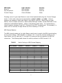
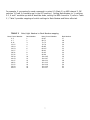
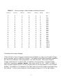
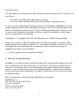
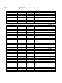
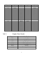
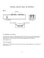
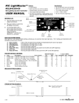
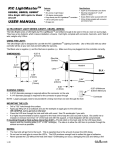
Light Master
LM-4
User Manual
Firmware release 3.01, Document version 1
Light Master User Manual
Section
Section
Section
Section
Section
Section
1
2
3
4
5
6
– Introduction
- Packing List
– Setup and Operation
- Light Master Control
- Warranty and Replacement
– MediaMation, Inc. Information
1. Introduction
Welcome to the Light Master MIDI-controlled dimmer. With this product, you have leaped into
the world of MIDI light control without losing your wallet. The Light Master is a fully functional
dimmer pack that does not require a high priced proprietary master controller. The only
required equipment is a sequencer, MIDI program controller, computer with MIDI software, or
any other MIDI source.
2. Packing List
Your package should contain the following:
1.
2.
3.
4.
The Light Master
Power Cord
This User Manual
Warranty/Registration Card
Please fill out the warranty card and return it today. By registering, you will receive valuable
information about product updates and new products, as well as activate your warranty.
3. Setup and Operation
The Light Master has MIDI IN and OUT/THRU ports, four power outlets, one power inlet, a fuse
access hole, and 2 sets of 8 DIP switches.
Connections
Power Inlet
Please use the enclosed 15 Amp power cord only! Most other cords have lower ratings.
Simply insert the appropriate end of the cord into the Light Master power inlet and the
2
standard end into a suitable AC electrical outlet.
MIDI Connectors
Connect a standard 5-pin MIDI cable to the MIDI IN port on the Light Master. Connect the
other end to the MIDI OUT of your control device. For daisy chaining additional Light Masters
or other MIDI devices, connect another MIDI cable from the MIDI OUT of the Light Master to
the MIDI IN of the next device in the chain.
Power Outlets
Connect the AC power plugs of your lights to the Light Master's power outlets. Only 600
watts (5 amps) per outlet and a maximum of 1800 watts (15 amps) per Light Master (this is
very important for your safety and product longevity.)
Setup
There are two groups of configuration switch modules (DIP switches) located at one end of
the Light Master (see figure.) SWITCH FUNCTIONS ARE DISABLED WHEN IN THE DOWN
POSITION!! In other words, a function is enabled when switches are off/up. Light Masters are
shipped with all functions enabled (all switches up.) Switch functions:
Module (Group) 1:
Switch 1 (1-1) -Reserved for future function
Switch 2 (1-2) -Power Up Fade On (DOWN to Disable)
Switch 3 (1-3) -Program Change (DOWN to Disable)
Switch 4 (1-4) -Control Change (DOWN to Disable)
Switch 5 (1-5) -Poly-Aftertouch (DOWN to Disable)
Switch 6 (1-6) -Note On (DOWN to Disable)
Switch 7 (1-7) -Note Off (DOWN to Disable)
Switch 8 (1-8) -Used to set the Bank number, which identifies the
set of lights is to be controlled
Module (Group) 2:
Switches 1-4 (2-1 through 2-4) -Also used to set the Bank Number.
These switches represent binary numbers; thus, the right most switch (4) is the least
significant bit. Value can be 0-31. *
Module (Group) 2:
Switches 5-8 (2-5 through 2-8) -Used to set MIDI channels.
These switches also represent binary numbers; thus, the right most switch (8) is the least
significant bit. Value can be 0-15.
3
Notes
* Bank number is explained further in the 'Light Master Control' section of this manual. Tables
which illustrate switch settings can be found in the appropriate sections as well.
All modes are enabled unless their appropriate DIP (disable) switch is set into the down
position. This will disable that particular mode of operation. For example, if one were to
switch number 4 down on the left module, the Light Master will ignore Control Change
commands yet still respond to all other commands. If switch 5 was set down as well, the unit
would ignore both Control Change and Poly Aftertouch commands but still respond to the rest
of the commands.
Upon power up, the Light Master fades the lights on to full intensity, unless Module 1 Switch 2
(1-2) is down (disabled.) "All Notes Off" (Control Change 120) is enabled, and when
received, the Light Master will turn all lights off. The Light Master auto-senses input power
frequency, so it can handle 60 Hz (North America) or 50 Hz (international.)
4. Light Master Control
The Light Master is a MIDI device that responds to 4 types of commands: Program Change,
Control Change, Note On/Off, and Poly Aftertouch (Switches 1-3 through 1-7.) All commands
may be active simultaneously, but disabling unnecessary commands is recommended. For
example, a 'Note On' command allows setting the intensity of the light, or dimming, while
'Program Change' has some dimming capabilities and several chase options for a versatile light
show.
Dimming
Dimming is accomplished through the use of three MIDI commands: 'Note On', 'Poly
Aftertouch,' and 'Control Change'. A typical Light Master configuration would have the
Note On, Note Off, and Control Change modes enabled. Each mode has its benefits for
particular situations. For example, Control Change may facilitate the use of sliders, whereas
Note On/Off may provide ease when operating quick hits on keyboard keys or controller
buttons. The instructions provided are written using Control Change references, but Poly
Aftertouch and Note On modes may be substituted. MIDI command parameter interpretation
is in the following table:
4
MIDI Mode:
Note On
Poly Aftertouch
Control Change
Light Number:
Note Number
Note Number
Control Number
Intensity:
Velocity
Pressure
Value
Dimming control in your Light Master is most often implemented using the 'Control Change'
mode. In this mode, there are two parameters: control number and value. Control
numbers are mapped to lights and value to each light's intensity. When using the Light
Master, Control number converts to bank number and light number, as described later in the
subsection entitled Bank Number. Value is how dimming takes place. It is expressed as a
step of intensity between 0 and 127 (0 being off and 127 the maximum.) For example, if a
value of 96 is received, the light will be set to an intensity of 75% on.
MIDI Channel Number
The MIDI channel number on the Light Master must be set to match the MIDI channel setting
on the control device. MIDI channel is a number 1-16. To set the channel number on the
Light Master, use DIP switches 2-5 through 2-8 located at the end opposite the MIDI Din
connectors. The following table shows the switch positions for MIDI channels 1-16.
TABLE 1
MIDI Channel
1
2
3
4
5
6
7
8
9
10
11
12
13
14
15
16
Switch Setting to MIDI Channel Mapping
Switch 5
U
U
U
U
U
U
U
U
D
D
D
D
D
D
D
D
Switch 6
Switch 7
U
U
U
U
D
D
D
D
U
U
U
U
D
D
D
D
U
U
D
D
U
U
D
D
U
U
D
D
U
U
D
D
5
Switch 8
U
D
U
D
U
D
U
D
U
D
U
D
U
D
U
D
Just a review of the previous DIP switch function listing:
Module 1 Switches
1-1
1-2
1-3
1-4
Reserved
Auto Fade Up Switch
Program Change disable
Control Change disable
1-5
1-6
1-7
1-8
PolyAftertouch disable
Note On disable
Note Off disable
Bank Number
Module 2 Switches
2-1
2-2
2-3
2-4
Bank
Bank
Bank
Bank
Number
Number
Number
Number
2-5
2-6
2-7
2-8
MIDI
MIDI
MIDI
MIDI
Channel
Channel
Channel
Channel
Description of Module Switches
Module 1:
1
Not used
2
Disables Auto fade Up feature enabled at unit power up
3
Disables LM-4 “pre-sets” which allow multiple light control by a single command
4
Disables execution of control change commands when in the on (down) position
5
Disables the execution of PolyAftertouch commands when in the on position
6
Disables the execution of Note On commands when in the on position
7
Disables the execution of Note Off commands when in the on position
8
Executes commands to groups of lights based on their location (bank)
Module 2:
2-1 – 2-4 Execute commands to groups of lights based on their location (bank)
2-5 – 2-8 Determine the MIDI channel on which the Light Master will operate
Bank Number
A bank number represents a group of 4 lights of a possible 128 . In other words, there are 32
banks of 4 lights each PER MIDI CHANNEL. Lights 1-4 are bank number one; lights 5-8 are
bank number two, etc. The next table (Table 2) shows the relation between Note/Light
number and Bank number. This applies only if you are using dimming (Note On, Control, or
Poly Aftertouch.) If you are using the Program Change mode, bank numbers do not apply.
6
For example, if you wanted to send commands to notes 0-3 (Bank 1) on MIDI channel 2, DIP
switches 1-8 and 2-4 would be up (in the OFF position.) Setting Bank Number to 1, switches
2-5, 6 and 7 would be up while 8 would be down, setting the MIDI channel to 2 (refer to Table
1.) Table 3 provides mappings of switch settings to Bank Number and Notes affected.
TABLE 2
Note/Light Number to Bank Number mapping
Note/Control Number
0-3
4-7
8-11
12-15
16-19
20-23
24-27
28-31
32-35
36-39
40-43
44-47
48-51
52-55
56-59
60-63
Bank Number
1
2
3
4
5
6
7
8
9
10
11
12
13
14
15
16
Note/Control Number
64-67
68-71
72-75
76-79
80-83
84~87
88-91
92-95
96-99
100-103
104-107
108-111
112-115
116-119
120-123
124-127
7
Bank Number
17
18
19
20
21
22
23
24
25
26
27
28
29
30
31
32
TABLE 3
Switch 8
U
U
U
U
U
U
U
U
U
U
U
U
U
U
U
U
D
D
D
D
D
D
D
D
D
D
D
D
D
D
D
D
Switch settings to Bank Number and Notes Affected
Switch 1
U
U
U
U
U
U
U
U
D
D
D
D
D
D
D
D
U
U
U
U
U
U
U
U
D
D
D
D
D
D
D
D
Switch 2
U
U
U
U
D
D
D
D
U
U
U
U
D
D
D
D
U
U
U
U
D
D
D
D
U
U
U
U
D
D
D
D
Switch 3
U
U
D
D
U
U
D
D
U
U
D
D
U
U
D
D
U
U
D
D
U
U
D
D
U
U
D
D
U
U
D
D
Switch 4
U
D
U
D
U
D
U
D
U
D
U
D
U
D
U
D
U
D
U
D
U
D
U
D
U
D
U
D
U
D
U
D
Bank #
Note #
1
2
3
4
5
6
7
8
9
10
11
12
13
14
15
16
17
18
19
20
21
22
23
24
25
26
27
28
29
30
31
32
0-3
4-7
8-11
12-15
16-19
20-23
24-27
28-31
32-35
36-39
40-43
44 47
48-51
52-55
56-59
60-63
64-67
68-71
72-75
76-79
80-83
84-87
88-91
92-95
96-99
100-103
104-107
108-111
112-115
116-119
120-123
124-127
Controlling Via Program Changes
If Note On/Off or Control Change commands are unavailable, you may use a Program Change
mode controller, such as a MIDI foot stomper. This mode provides limited dimming capabilities
but allows for 8 different chasing algorithms, each with 8 speeds. When using Program
Change mode, Switch 1-3 must be OFF, or enabled (in the up position.) Program Change
mode has 1 parameter, program number, with values from 0 to 127. Table 5 on Page 11
maps out what happens to each of the four-light banks on the Light Master for each Program
Number. This allows for 16 channels of four lights each (a total of 64 lights controlled) using
this method. To turn a chase mode off, send a program change of 0 to the Light Master.
8
System Exclusive
The Light Master has incorporated the MIDI system exclusive command as well. Currently, you
can find out:
- The version of firmware your Light Master is running;
- The current switch settings (MIDI channel, Bank Number, configuration stuff.)
To do this, send the MIDI system exclusive command: FOh followed by MediaMation's system
exclusive address: 00h 01h 08h, a MediaMation product code: 01h for the Light Master, and
finally, the command you wish to send. The only command implemented at this point is 00h
for version and configuration information. When you send this command to a Light Master,
what you will get back is the following:
LightMaster 3.0 - Copyright 1996-99 Topaz Enterprises, Inc. CONFIG: 0Xhex#1hex#2
Where X is a number 0-3 decimal representation of the binary settings of switches 1 and 2,
hex#1 represents the settings of switches 3-6, and hex#2 the settings of switches 6-10 We
will expand upon the system exclusive command set in future versions and accept all
suggestions and ideas for enhancements.
** 'h' after a number denotes hexadecimal notation
5. Warranty and Replacement
MediaMation, Inc. warrants the enclosed Light Master MIDI controlled light dimmer pack to be
free of material and manufacturing defects for a period of 1 year after the original date of
purchase. This warranty does not include damage to the product resulting from accidents,
misuse, or use of the product for other than intended purposes. If the product is defective
within the warranty period, MediaMation will repair or replace the unit (at our option) without
an additional charge.
Return transportation fee will be paid by MediaMation if returned to:
MediaMation, Inc.
2461 W. 205th Street, Suite B-100
Torrance, CA 90501
Phone: (310) 320-0696
Fax: (310) 320-0699
9
LightMaster Factory Pre-sets
TABLE 4
Program #
Light 1
Light 2
Light 3
0
1
Turn
Turn Off
Chasing
Off
2
Turn Off
3
4
Turn Off
5
Turn Off
6
7
Turn Off
Turn Off
Turn Off
Turn Off
Turn Off
Turn Off
Turn Off
Turn Off
8
9
10
11
Turn Off
Turn Off
Turn Off
Turn Off
14
15
Turn Off
Turn Off
Turn Off
Turn Off
Turn Off
Turn Off
12
13
Light 4
Turn Off
Turn Off
Turn Off
Turn Off
Turn Off
Turn Off
Turn Off
Turn Off
Turn Off
Turn Off
16
17
50% On
18
19
20
50% On
21
50% On
50% On
22
23
50% On
50% On
50% On
50% On
50% On
50% On
50% On
50% On
24
50% On
25
26
50% On
27
50% On
28
29
50% On
30
31
32
50% On
33
34
75% On
35
75% On
36
37
75% On
38
50% On
50% On
50% On
50% On
50% On
50% On
50% On
50% On
50% On
50% On
50% On
50% On
50% On
50% On
50% On
75% On
75% On
75% On
75% On
75% On
10
75% On
Program #
Light 1
Light 2
Light 3
39
40
41
42
43
44
45
46
47
48
49
50
51
52
53
54
55
56
57
58
59
60
61
62
63
75% On
75% On
75% On
TABLE 5
75% On
75% On
75% On
75% On
75% On
75% On
75% On
75% On
75% On
75% On
75% On
75% On
Light 4
75% On
75% On
75% On
75% On
75% On
75% On
75% On
75% On
100% On
100% On
100% On
100% On
100% On
100% On
100% On
100% On
100% On
100% On
100% On
100% On
100% On
100% On
100% On
100% On
100% On
100% On
100% On
100% On
100% On
100% On
100% On
100% On
Program Chase Pre-sets
Program #s
Chase Function
64-71
Left to Right
72-79
Left to Right Sweep
80-87
Right to Left
88-95
Right to Left Sweep
96-103
Pong Left-Right-Left
104-111
In to Out
112-119
Lights 1 & 3 to Lights 2 & 4
120-127
Flash
11
100% On
100% On
100% On
100% On
100% On
100% On
100% On
100% On
Previously mentioned figures and illustrations
LM-4
4
Outlets
3
2
1
Fuse Holder
MIDI Jacks
Switch Module 1
Switch Module 2
6. MediaMation Information
For information, to drop us a line telling us you're out there, or let us know interesting facts,
references, 'Did you know,' or anything else that's on your mind, please write to us at the
above address, visit our web site at: http://www.mediamat.com, or E-mail us at
[email protected]
Technical Support
Please call: (310) 320-0696, visit our web site at http://www.mediamat.com, or E-mail us at
[email protected]
12