1
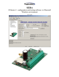
SERA
GTGPS v1 configuration and testing software in Microsoft Windows environment
User‟s guide
Content
1.
2.
3.
4.
5.
Installation of SERA software ................................................................................................................ 2
USB drivers installation.......................................................................................................................... 4
Selection of COM port ......................................................................................................................... 10
Connection of the module to your PC .................................................................................................. 12
Work with the software SERA ............................................................................................................. 12
5.1. Content of the module configuration ............................................................................................ 14
5.2. Main Window of the software SERA (System options) ............................................................... 15
5.3. Window [GSM communication options] ...................................................................................... 18
5.4. Remote Control by Dialling (Remote Control by Dialling) .......................................................... 19
5.5. Window [Outputs] ......................................................................................................................... 20
5.6. Window [Inputs] ........................................................................................................................... 22
5.7. Window “Service text summary” ................................................................................................. 28
5.8. Window [Text summary] .............................................................................................................. 29
5.9. Window [Testing and Diagnostic window] ................................................................................. 30
6. Saving of GTGPS module configuration into PC ................................................................................ 32
7. Installing of saved configuration into the module GTGPS .................................................................. 32
8. Updating of GTGPS software version .................................................................................................. 33
1. Installation of SERA software
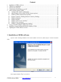
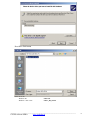
Open the folder containing installation of the software SERA. Click the file „SERA setup.exe“ from the mentioned
folder.
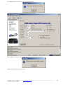
Fig. 1
In the displayed Window
Fig. 1 press [Next>].
__________________________________________________________________________
GTGPS software SERA
www.topkodas.lt
2
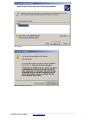
Fig. 2
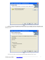
Installation directory will be displayed in the Window Fig. 2 (fig.2). If installation directory of the software is OK,
press [Next]. If you would like to install the software in the other directory press [Change], specify other installation directory
and then press Next>.
Fig. 3
Check if the correct data are entered and press Install in the displayed Window ( Fig. 3) (Fig.3).
__________________________________________________________________________
GTGPS software SERA
www.topkodas.lt
3
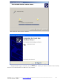
Fig. 4
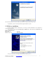
After successful installation of the software SERA, press [Finish] in the displayed Window Fig.
4 (fig. 4).
Congratulations, you have successfully installed the application SERA in your PC.
2. USB drivers installation
In order to configure GTGPS via USB interface, it is necessary to install USB DRIVER . Drive configuration is
available in the file usbser.inf
After connection of USB cable (the module must be supplied with + 12V) to the PC via USB interface, OS
Windows will find USB driver.
Driver configuration:
Windows XP
usbser.inf .
Windows 7 x86 or x64
usbser_x86_x64.inf
Fig. 5
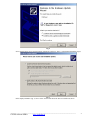
Select [„No, not this time“] in the displayed Window (Fig.5) and press [„Next>“].
__________________________________________________________________________
GTGPS software SERA
www.topkodas.lt
4
Fig. 6
Select „Install from a list or specific location (Advanced)“ and press „Next>“ in the displayed Window (Fig.6).
Fig. 7
In the displayed Window (fig. 7) select : Don„t search I will choose the driver to install. Press Next>
__________________________________________________________________________
GTGPS software SERA
www.topkodas.lt
5
Press Have Disk button
Select driver file:
Windows XP
Windows 7 x86 or x64
usbser.inf .
usbser_x86_x64.inf
__________________________________________________________________________
GTGPS software SERA
www.topkodas.lt
6
Press Next
Press Continue Anyway
__________________________________________________________________________
GTGPS software SERA
www.topkodas.lt
7
Wait while the driver will be installed
Fig. 8
Displayed Window (fig.8) means that your PC has found file necessary for driver's installation and successfully
installed it. Press Finish Installation of USB Serial Config is finished.
__________________________________________________________________________
GTGPS software SERA
www.topkodas.lt
8
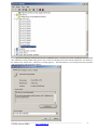
Open Device Manager window and in the row (COM&LPT) press + in order to see all PC COM ports. The row should
show USB Serial Config (COMx). Drag mouse cursor on this row and right click on the menu item Properties. You should see
the window below with the note: „This device is working properly“ . This means that PC is successfully prepared for operation
with configuration-testing application „SERA“.
__________________________________________________________________________
GTGPS software SERA
www.topkodas.lt
9
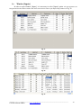
3. Selection of COM port
After installing drivers you should check what COM port number has been assigned to the USB module. To perform
this task in Windows environment follow the instructions mentioned below.
Attention! The module should be connected to +12V (connection leads: black (-), red (+)) and to a PC via USB interface.
DO NOT power the module from PC power supply unit, because absence of common grounding between two PC power
supply units may damage the module.
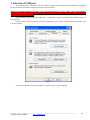
Open the Window [System Properties] (path: Start > Control Panel > System). [System Properties] Window (Fig. 9) is
being displayed.
From the Window [System properties] select the tab [Hardware]. After selection of the tab [Hardware] Window (Fig.
9) will be displayed.
Fig. 9
Select [Device Manager] from the tab [Hardware]. Window (Fig. 10) will be displayed.
__________________________________________________________________________
GTGPS software SERA
www.topkodas.lt
10
Fig. 10
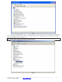
In [Device Manager] Window click „+“ symbol near [Ports (COM & LPT)] in order to scroll [Ports (COM & LPT)]
menu. If the module is powered with +12V and it is connected to the PC via USB port, thus upon scrolling Ports (COM &
LPT), Window (Fig. 11) will be displayed.
Attention! If the module GTGPS is not powered with +12V and it is not connected to the PC via USB interface, menu
[Ports (COM & LPT)] item [USB Serial Port] will not be visible.
Fig. 11
__________________________________________________________________________
GTGPS software SERA
www.topkodas.lt
11
From the displayed Window (Fig. 11) you must check what COM port is assigned to USB interface. [USB Serial Port
(COM3)] is displayed in the example. This means that USB will be assigned to the third COM port. Remember this COM
port number and proceed with the clause Work with the software SERA
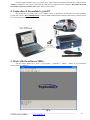
4. Connection of the module to your PC
The module must be powered with (+12V >500mA) voltage, it should have inserted SIM card (with replenished
account and removed PIN CODE REQUEST), connected GSM and GPS antennas and the module must be connected to the
PC via programming cable.
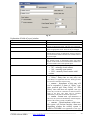
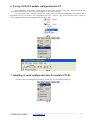
5. Work with the software SERA
Start the software SERA. Go to „Start“ > „All programs“ > „Topkodas“ > „SERA“ > „SERA“ or go to installation
directory and click „SERA.exe“.
Fig. 12
__________________________________________________________________________
GTGPS software SERA
www.topkodas.lt
12
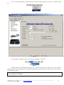
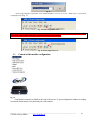
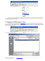
If you are sure that the module is fully connected to PC and power supply, please go to Devices > GTGPS v1. ( Fig.
13)
Fig. 13
After you make a selection, configuration window (System Options) will be opened (Fig. 14)
Fig. 14
Set the COM port to initialize GTGPS. Go to [Setup] > [Serial Port...] ( Fig.
15).
Fig. 15
Window [Serial Port Setup] should be displayed (Fig. 16). Scroll the list and select COM port, you saw in [Device
Manager] window. In the example the port USB Serial Config (COM3) was assigned to the module. Therefore select from the
list COM3 and press OK. .
Attention! If you do not know the COM port you have connected the module, please open Device Manager and read the
chapter: Selection of COM port
__________________________________________________________________________
GTGPS software SERA
www.topkodas.lt
13
Fig. 16
Upon setting COM port, information of the module should be read out. Go to File > Read Device or press Read
Configuration icon (Fig. 17)
Fig. 17 Read Configuration icon
Attention! Each time after configuring the module press [File] > [Write Device] or press Send Configuration icon (Fig.
18) thus the software SERA will include configuration changes into the module!
Fig. 18 Send Configuration icon.
5.1.
Content of the module configuration
Fig. 19
Configuration content is available at the side of the screen. To open configuration window according
to selected content menu, click preferred part of the content.
__________________________________________________________________________
GTGPS software SERA
www.topkodas.lt
14
5.2.
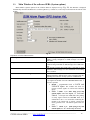
Main Window of the software SERA (System options)
Main Window (System Option) of the software SERA is displayed in Fig. ( Fig. 20) This Window is displayed
automatically when the GTGPS device is selected ([Devices] > GTGPS v1). It also may be selected from the content of the
module.
Fig. 20
Explanation of fields of Main Window:
Installer password
User password
Test time
Reset test counter after ARMing
Lock/Unlock
It is installer password comprised of 6 symbols, when the
module is being configured via SMS messages. See INST
codes table.
It is installer password comprised of 6 symbols, each time the
module is being controlled via SMS messages. See USER code
table.
Time period to inform how much time it will take to send
informative SMS message to a user. Discretion of test setting
time is one hour.
If a check box nearby this note will be checked, time of
sending informative SMS message will be calculated from the
beginning each time after security system is in ARM mode.
When connecting the module to the central lock, it is necessary
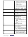
to set signals the module will enter ARM/DISARM modes. 5
versions is possible:
Disable – programmable block of LOCK and
UNLOCK inputs. The module will show no
reaction towards signals in LOCK and UNLOCK
inputs.
Mode 1 (Mode 1 (V+ Pulse using Lock and
Unlock inputs) uses two inputs, i.e. Lock and
Unlock. Lock input sets ARM mode after pulsing
or steady signal. Unlock sets DISARM mode. It is
comfortable to use 1 or 2 mode when connecting the
module to the central lock of vehicle. Central lock
mostly generates lock and unlock signals with two
wires.
Mode 2 (Mode 2 (V- Pulse using Lock and
Unlock inputs) as in 1 mode only inverted.
__________________________________________________________________________
GTGPS software SERA
www.topkodas.lt
15
Mode 3 (Mode 3 (V+ Level using Lock input)
uses only one Lock input. Unlock input is not
used. These modes are comfortable to use when
activating/deactivating the system by using switch or
other access control device.
Mode 4 (Mode 4 (V- Level using Lock input) as
in 3 mode only inverted.
Entry Delay
Entry Delay
Siren Time
Indication
Mode 5 (Mode 5 (V+ >500ms Pulse Lock input))
used only one Lock input. Unlock input is not used.
The module ARM/DISARM state may be changed via
voltage pulse longer than 500ms. It is possible to use a
button or other control device, which will generate
voltage pulse.
Mode 6 Mode 6 (V+ >500ms Pulse Lock input))
similar as 5 mode only inverted.
Input time in seconds. The system starts calculating this
time period after Delay type zone breaking. If during
that time the security system will not be disarmed, The module
will activate alarm state, i.e siren will be switch on and SMS
will be send about alarmed zones.
It is insensibility time (seconds) of the module into
Delay and Interior type inputs before the module
enters to ARM mode. This means that during calculation
of this time period, the module will not activate alarm even if
inputs will be activated.
This time value specifies how long the Siren of security system
will be active after occurrence of alarm. Time period should be
set in seconds from 1 sec to 999 sec.
on/off (energy saving) – if this box is checked it means
that setting is On. If the box is not checked the
setting is in off (energy saving).
On mode – all LEDs available on the module
are active and indicate activity of the
module.
Off (energy saving) mode - lights only red
LED, operation of GSM modem is being
indicated.
*red „control“ LED is on bus leads are always on
not depending on Indication mode.
Siren Signal on ARM/DISARM
Auto re-ARM
Temperature
Hardware details
When the function is active and the security system is turned
into ARM state, siren will beep once, when turning into
DISARM state - it will beep twice.
Automated activation of the system, if a door has nor been
closed after DISARMing the system.
It is temperature scale. Two scale types are possible, one of
which may be selected after scrolling menu near the note
“Temperature”:
Celsius – temperature indications according to Celsius
scale.
Fahrenheit – temperature indications according to
Fahrenheit scale.
This is info about „GTGPS“ module:
HW – hardware version of the module.
Boot – start up program version (BOOT) This
part of the program is able to update Firmware SW.
SW – Firmware version of the module.
__________________________________________________________________________
GTGPS software SERA
www.topkodas.lt
16
Button [Reset Module] will reset the module as programmed. This function operates similarly as actual built-in RESET module.
If this function will not operate, in the event USB Serial Port is not open or FW program of the module is not functioning
properly.
__________________________________________________________________________
GTGPS software SERA
www.topkodas.lt
17
5.3.
Window [GSM communication options]
In order to open Window [GSM SMS and DIAL communication options] it is necessary to select „GSM
Communication“ clause Fig. 19 from the left side. The Window Fig. 21 including user table whom GSM SMS messages are
being sent and calls are being made. User number up to 16 Double click on the selected line will show selected user window
Fig. 22to set what events should be sent to the specified number.
User numbers should be entered with international code. Near the telephone number of each user, check boxes which
events will be sent to that user.
Fig. 21
Fig. 22
Explanation of fields of [GSM communication options] Window:
ID
User Phone SMS and DIAL
Sending SMS (Alarm/Restore)
Dialling to USER (Alarm/Restore)
SMS error limit
Limit of dialling
ID of the user to whom send SMS and make a call.
This column includes user numbers to whom GSM SMS
messages will be sent and short calls will be made. User
number should be entered with international code.
The events with check boxes will be send to selected
users via SMS
A user will be notified about these events (the check bow
should be checked) by making him a short call
SMS repetition limit in a case of failure to send SMS.
It is a figure, which specifies how many times to call to a
user‟s telephone number, in the event of alarm or if a user
does not cancel call of the module. If a user after 15 sec
will reject a call, the module will stop making calls till
another event.
__________________________________________________________________________
GTGPS software SERA
www.topkodas.lt
Fig. 2
Fig. 2
18
5.4. Remote Control by Dialling (Remote Control by Dialling)
To open Window [Remote Control by Dialling], it is necessary to select [GSM Remote Control]. A
window Fig. 23 will be displayed including users table. These users would be able to control the module by dialling. The
module will identify caller ID and if this ID will be available in the table, the module will perform selected action. It is possible
to select few actions for one number, however some of these actions may disturb each other, e.g. if MIC and GPS are selected.
In such case the microphone will not be able to be turned on, because when sending SMS with GPS parameters, the module
will automatically reject the call.
User number up to 400
Fig. 23
Explanation of fields of [Remote Control by Dialling]:
ID
Remote User Phone
OUT1, OUT2,OUT3,OUT4
ARM/DISARM command.
MIC
GPS
ID number of a user who is able to control the module by
dialling up to 400.
Telephone numbers of users who will be able to control
the module by dialling should be entered in this column.
User number should be entered with international code.
Where the check boxes are checked, these inputs will be
switched, if a user will call from this number. Preferred
input may be assigned to each user„s number. Thus
different users are able to control different objects.
If this check box is checked, a user will be able to
ARM/DISARM the security system by dialling.
If this check box is checked, a user will be able to activate
microphone and to switch on voice listening.
If this check box is checked, when dialling to the
module, the module will send SMS with GPS coordinates
to the number from which the call has been made.
__________________________________________________________________________
GTGPS software SERA
www.topkodas.lt
19
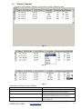
5.5. Window [Outputs]
In order to open Window [Outputs], it is necessary to select [Outputs] option.
Fig. 24
Fig. 25
Fig. 26
Explanation of fields of [Outputs] Window:
ID
Name
Out ON text
Out OFF text
Out definition
Output ID number
Output name
It is a text, which will be sent to a user after activation of
output by the module. This text may be changed.
It is a text, which will be sent to a user after deactivation
of output by the module. This text may be changed.
Output activity algorithm may be selected from scrolled
menu, seeFig. 25:
__________________________________________________________________________
GTGPS software SERA
www.topkodas.lt
20
CTRL/SMS/DIAL – output will be
possible to control via SMS message,
short call or commutation via selected
input. This algorithm may be used for ignition
blocking, for gate control or for remoter starting
of a car etc.
SIREN – output used for connection of
siren. Used for generating of voice
signal in the event of alarm.
BUZER – sound signalling device. Upon
alarm of the zone beeps continuously. When
security system starts calculating Exit time “Exit
Delay”, the user is able to hear short voice
signals. When 10 seconds are left till the
activation, signals are being repeated each 0.5
seconds. If after expiry of delay time all zones
remains unalarmed, the system turns into ARM
state along with conformation beep.
ARM State – state of alarm system
ARM/DISARM. For light indication may be
used. When the output is set for operation in
pulsating mode, this feature may be used to close
car windows or roof ventilation. Impulse time
should be set 20-30 seconds. When the security
system will be turn on, the output will generate
signal to close windows.
Inputs OK - if any of zones is disturbed,
the output will be alarmed. This feature is
usually used for indication whether all zones are
in order.
Light Flash – used for connection of
light signal. Upon alarm of the security system
the light starts blinking. Lights will also blink
when activating/deactivating the security system.
This feature may be applied to connect car
direction signals.
Out pulse time
It is time in seconds, which indicates duration of
impulse, when Pulse type is being selected in the
column [State Mode]
Invert
Option to invert the output. If the check box is to be
checked, the output will work as inverted.
Output commutation type, see Fig. 26.
Pulse – the output will work in single
State mode
pulse mode. Pulse time (seconds) should
be set in [Out pulse time] column.
Steady – output will work on the steady
level till the next commutation.
__________________________________________________________________________
GTGPS software SERA
www.topkodas.lt
21
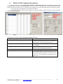
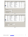
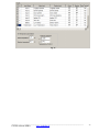
5.6. Window [Inputs]
In order to open Window [Inputs], it is necessary to select [Inputs] option. All input parameters are
being described in this window. Double click on the selected line in order to open input settings window see Fig. 30
Fig. 27
Fig. 28
Fig. 29
__________________________________________________________________________
GTGPS software SERA
www.topkodas.lt
22
Fig. 30
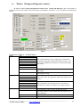
Explanation of fields of [Inputs] window:
In
Input Name
Alarm text
Restore text
Alarm
Restore
Input Name
Input number
Input name
It is the text, which will be received by a user after alarm
response of appropriate sensor. This text may be changed.
It is the text, which will be received by a user after
restore of appropriate sensor. This text may be changed.
If the box is checked it means that the module will react
towards alarm response of appropriate sensor. If the box
is not checked the module will not react towards alarm of
the present input.
If the check box is checked, it means that the module will
react towards restore of appropriate sensor after alarm
response. If the check box is not checked the module will
not react towards restore of the present input.
Input type you may select after scrolling menu:
NC – normally closed contact;
NO – normally open contact;
EOL - normally closed contact with 1
resistor
Input Def.
Input operation type you may select after scrolling menu:
Delay – Entry zone. Set "Entry delay" and
"Exit Delay" are applied for this zone. Such type zones
are used for connection of door sensor.
Interior – disturbance of this zone will
not be responded, if alarm of “Delay” type
zone occurred and “Entry Delay” or “Exit
Delay” time still have not expired. Such type
zones may be used for connection of motion sensor in
front of the door. The input will be activated
immediately if the door has not been open before.
Instant – Instant zone. Upon disturbance of
this zone, the system will immediately activate burglary
alarm. If the security system was ARM‟ed.
24 hours - Upon disturbance of this zone,
the system will activate burglary alarm not
depending whether the security system is
ARM or DISARM. The applications of this type
__________________________________________________________________________
GTGPS software SERA
www.topkodas.lt
23
zones are safes, storehouses, tampers of the sensors.
Silent - silent zone is always active not
depending on whether the security system is
ARM or DISARM. Upon disturbance of this zone,
SMS messages are being generated but the siren will
not be activated. These zones may be applied for
voltage, temperature control, AC mains failure control
and for alarm of silent panic.
Fire - this zone is always active not
depending on whether the security system is
ARM or DISARM. The zone generates a special
siren signal with interruptions. The zone is applied for
smoke sensors and for fire alarm.
It is the time in milliseconds, which indicates the shortest
signal for reaction of the module. If signal is shorter than
indicated, the module will ignore it.
The time period in seconds, during this time repeatable
zone events are ignored.
Additional input function. Lock/Unlock blockage
conditions. The following settings are possible:
Disable- additional function off
Unlock Blocking condition
Lock Blocking condition
Lock/Unlock Blocking condition
Input reaction speed
If check box is checked, this is to inform that upon input
alarm, activation of the module will be blocked.
In7 forced ARMing (special function)
Disable - additional function off
Unlock Blocking condition
Lock Blocking condition
Lock/Unlock Blocking condition
Force Arming – if the module is in
Input speed
Repeat time
Input 4 (Fig.
31)
Input 5 (Fig.
32)
Input 6 (Fig.
33)
Battery (Fig.
DISARM state, thus after selecting this
function, the module will go to ARM
mode after alarm response of Input7
(siren) zone.
Min siren time - it is time in seconds,
indicating the time period the siren
should be active in order to trigger that
zone.
Input reaction speed
In8 Low Battery parameters
Alarm voltage – voltage the module is
connected to; when this voltage is reached, the 8
zone will be alarmed.
Restore voltage – voltage the module is
34)
connected to; when this voltage is
reached, the 8 zone will be restored.
Temperature (Fig.
35)
Calibration – coefficient, if changed voltage
indications might be calibrated.
In9 Temperature parameters
Alarm temperature – when this temperature
will be reached 9 zone will be alarmed.
Restore temperature - when this temperature
__________________________________________________________________________
GTGPS software SERA
www.topkodas.lt
24
will be reached 9 zone will be restored.
Additional Calibration – by changing X and Y
coefficients, which influence temperature
calculation formula, it is possible to calibrate
temperature showings.
Attention! In order to change temperature scale (C/F)
go to "Main Window", select preferred temperature
scale ("Temperature") and after this change send
configuration into the module (“Write Device”).
Fig. 31
Fig. 32
__________________________________________________________________________
GTGPS software SERA
www.topkodas.lt
25
Fig. 33
Fig. 34
__________________________________________________________________________
GTGPS software SERA
www.topkodas.lt
26
Fig. 35
__________________________________________________________________________
GTGPS software SERA
www.topkodas.lt
27
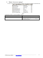
5.7. Window “Service text summary”
In order to open [Service text summary] Window select [Service text summary] from the left section.
Fig. 36
Explanation of fields of “Service text summary” Window:
Name of Status Event
Event Text
Send
Event name
Event test, which may be changed
If the check box is checked, the message about a certain
event will be sent to a user, if it is configured in
[Communications] window.
__________________________________________________________________________
GTGPS software SERA
www.topkodas.lt
28
5.8.
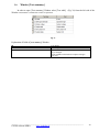
Window [Text summary]
In order to open [Text summary] Window select [Text table] (Fig. 36) from the left side of the
Window. This Window is intended for creation of equivalents.
Fig. 37
Explanation of fields of [Text summary] Window:
ID
Text name
Text
Text number
Text in English
Equivalent of the text available in „Text name“, which
may be changed.
Words available in this field will comprise messages
being sent.
__________________________________________________________________________
GTGPS software SERA
www.topkodas.lt
29
5.9.
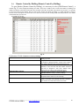
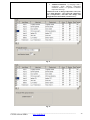
Window [Testing and Diagnostic window]
In order to open [Testing and Diagnostic window] select [Testing and Diagnostic] option. This Window is
intended for testing of the module, for operation analysis and diagnostics. This feature is very convenient when installing the
module.
Fig. 38
Explanation of fields of “Testing Window”:
Inputs
IN1
IN2
IN3
IN4
IN5
IN6
IN7
IN8
Lock
Unlock
Outputs states
GSM info
Out1
Out2
Out3
Out4
Button Out1 On/Off
Button Out2 On/Off
Button Out3 On/Off
Button Out4 On/Off
IMEI
SIM card
Signal level
Registration
This is alarm indication of each of eight inputs. Checked check
box nearby the appropriate input means that the said input – zone
was activated. Number near each input is a coefficient indicating
input voltage.
Lock Input indication. Number nearby is a coefficient indicating
input voltage.
Unlock Input indication. Number nearby is a coefficient
indicating input voltage.
Checked box nearby the appropriate output means that this output
is active.
By pressing buttons (on/off) output states are controlled. It is
convenient to use when it is necessary to test outputs operation.
IMEI number of GSM modem available in the module.
If note READY is visible, it means that SIM card is fully
functioning. Otherwise, check whether PIN code request is off or
replace SIM card.
Signal strength of GSM communication.
State of GSM modem registration to GSM network.
__________________________________________________________________________
GTGPS software SERA
www.topkodas.lt
30
SMS centre number. This number should be checked if it correct.
If this number is incorrect. SMS messaging may be impossible.
This number may be changed after inserting SIM card into any
mobile phone.
power supply voltage the module is connected to. Nearby number is value of ADC voltage. When
multiplying this number by the coefficient available in IN8 window Fig. 33, voltage value (V)
will be achieved.
Temperature of temperature sensor. The number nearby is temperature ADC value used to
calculate temperature according to the formula: Temperature=X*ADC+Y. X and Y coefficients
may be changed in temperature window in order to additionally calibrate temperature measuring.
These coefficients see Fig. 34. After performing additional calibration, it is possible to achieve
precise temperature measurement.
Indication that at the moment the module is in ARM
ARM
SMS Service Centre
Address
System voltage
Temperature
System State
DISARM
WAITING ARM
Latitude
Longitude
Altitude
Test time
Speed
PDOP/VDOP/HDOP
GSM info
Fix Quality
GPS Mode
Sat Used
Sat in View
Geofence Dist.
Switch on
testing mode
Switch on
testing mode
mode.
Indication that at the moment the module is in DISARM
mode.
Module mode when Exit Delay time is being calculated.
Showings of geographic latitude defined by GPS receiver
Showings of geographic longitude defined by GPS receiver
Showings of geographic altitude defined by GPS receiver
Showings of height above sea level defined by GPS receiver
Speed of GPS receiver movement
PDOP [Position dilution of precision] - the term to specify the
satellite layout on GPS precision in real time. This is the
coefficient, which is shown on the receiver's screen thus
providing information on accuracy of carried out works. If the
coefficient is small, work conditions are ideal and measurement
bias is minimal, and if the coefficient is big - it is recommended
to wait for the better satellite layout . If registered PDOP is too
big, the receiver will simply not to allow performing necessary
jobs. When measuring under 1-3 PDOP coefficient value,
measuring bias will be minimal.
Accordingly:
VDOP - vertical accuracy
HDOP - horizontal accuracy
GPS receiver's state whether communication is available. The
following conditions are possible:
Not Fixed - No communication
Fixed-GPS - communication fixed
Dgps Fixed - GGPS communication is fixed
Unknown Status - status unknown
GPS communication type:
Not Fixed - No communication
2D
3D
Number of satellites used to calculate GPS coordinates setting
General number of visible satellites
Showings of measured distance from geofence zone till the centre
of the module
Pressing this button starts testing of the module.
Pressing this button stops testing of the module.
__________________________________________________________________________
GTGPS software SERA
www.topkodas.lt
31
6. Saving of GTGPS module configuration into PC
After configuration of the module, all settings may be saved at PC. It enables to save time, when next time the same
configuration will be used – it will not be necessary again to set the same parameters.
If you want to save that is already recorded by the module, firstly you must read configuration of the module. [File >
Read Device] see Fig. 39 In order to save configuration go to [ File > Save As... [Fig. 40 or press icon [Save] icon Fig. 41.
Enter configuration parameter in the displayed table and press „OK“.
Fig. 39
Fig. 40
Fig. 41
7. Installing of saved configuration into the module GTGPS
In order to start saved configuration go to [File] > [Open] Fig. 42 or press [Open] iconFig. 43
Fig. 42
__________________________________________________________________________
GTGPS software SERA
www.topkodas.lt
32
Fig. 43
Fig. 44
Click the file of saved configuration or press “Open” in displayed Window. Now all parameters of saved configuration
have been loaded into application SERA. If no any other changes are necessary, press [File] > [Write Device] Fig. 44 in order
to send this configuration into the module.
8. Updating of GTGPS software version
The latest software version may be found www.topkodas.lt . If a version of your module is older, please update it (to
find out the version of your GTGPS software version (SW) send Test SMS from your module). For this purpose press [Update]
in the menu list or [Update module] icon, Fig. 45. Specify the file of the newest software version and press [Open]. Follow
further instructions of the program.
Fig. 45
Select Firmware file of the module:
__________________________________________________________________________
GTGPS software SERA
www.topkodas.lt
33
Press RESET button once and click “OK” in the displayed table.
You will see the following progress bar at the bottom of the window:
When updating of firmware will be finished, the system will displayed the table below:
Then press RESET button. Then press OK.
__________________________________________________________________________
GTGPS software SERA
www.topkodas.lt
34
Read configuration of the module [File->Read Device].
Go to Main Window. Check whether the firmware has been updated. SW: xxxxxxxxx
Programme version is also visible below:
__________________________________________________________________________
GTGPS software SERA
www.topkodas.lt
35