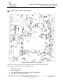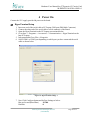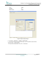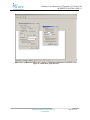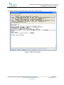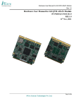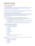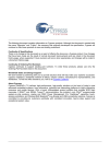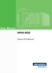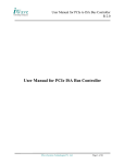
1
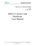
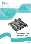
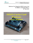
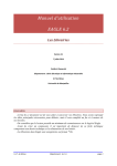
Hardware User Manual for G7D generic Q7 Carrier Card iW-PRDVD-UM-01-R1.0-REL1.0 Hardware User Manual for G7D generic Q7 Carrier Card iW-PRDVD-UM-01-R1.0-REL1.0 2nd ,Nov, 2011 iWave Systems Technologies Pvt. Ltd. (Confidential) Page 1 of 33 Hardware User Manual for G7D generic Q7 Carrier Card iW-PRDVD-UM-01-R1.0-REL1.0 Author’s RG APPROVAL Name Mr. Immanuel Distribution Function Associate Director Organization iWave Systems Date Signature iWave Systems Technologies Pvt. Ltd. CONTACT INFO Name iWave Systems Technologies Pvt. Ltd. No. 7/B, 29th Main, BTM Layout 2nd Stage, Bangalore - 560 076. INDIA. Telephone +91-80-26786245, +91-80-26683700 e-mail [email protected] DOCUMENT IDENTIFICATION Project Name Document Name Document Home Release No Status Audience iW-RAINBOW-G7 iW-PRDVD-UM-01-R1.0-REL1.0- Rainbow G7D HW Usermanual file://server/prdvd/svn/trunk/iW-PRDVD-PF01-R1.0/iW-PRDVD-HF-01-R1.0/iWPRDVD-UM-01-R1.0 REL 1.0 Release iWave Systems Technologies Pvt. Ltd. (Confidential) Page 2 of 33 Hardware User Manual for G7D generic Q7 Carrier Card iW-PRDVD-UM-01-R1.0-REL1.0 DOCUMENT REVISION HISTORY Revision 1.0 2 nd Date Nov 2011 Change Description Initial Draft Release Updated By Raghavendra Reviewed By PROPRIETARY NOTICE: This document contains proprietary material for the sole use of the intended recipient(s). Do not read this document further if you are not the intended recipient. Any review, use, distribution or disclosure by others is strictly prohibited. If you are not the intended recipient (or authorized to receive for the recipient), you are hereby notified that any disclosure, copy or distribution or use of any of the information contained within this document is STRICTLY PROHIBITED. Thank you. “iWave Systems Tech. Pvt. Ltd.”s iWave Systems Technologies Pvt. Ltd. (Confidential) Page 3 of 33 Hardware User Manual for G7D generic Q7 Carrier Card iW-PRDVD-UM-01-R1.0-REL1.0 TABLE OF CONTENTS 1 INTRODUCTION .................................................................................................................. 7 1.1 1.2 1.3 2 PURPOSE ............................................................................................................................. 7 SCOPE ................................................................................................................................. 7 GLOSSARY .......................................................................................................................... 7 HARDWARE DETAILS ....................................................................................................... 8 2.1 GENERIC Q7 CARRIER CARD CONNECTOR DETAILS ........................................................... 8 2.2 BOARD CONFIGURATIONS AND DEFAULT FEATURES .......................................................... 9 2.3 HARDWARE SETUP DETAILS ............................................................................................. 11 1.1.1 Power Supply Connection Procedure ....................................................................... 11 1.1.2 Serial Cable Connection Procedure ......................................................................... 12 1.1.3 USB OTG Connection Procedure ............................................................................. 13 1.1.4 SD/MMC Connection Procedure .............................................................................. 14 1.1.5 Audio In Cable Connection Procedure ..................................................................... 15 1.1.6 Audio Out Cable Connection Procedure .................................................................. 16 1.1.7 VGA Cable Connection Procedure ........................................................................... 17 1.1.8 Ethernet Cable Connection Procedure ..................................................................... 18 1.1.9 USB Host 0 Connection Procedure .......................................................................... 19 1.1.10 USB Host 2 Connection Procedure .......................................................................... 20 1.1.11 USB Host 4 Connection Procedure .......................................................................... 21 1.1.12 CAN Connection Procedure ..................................................................................... 22 1.1.13 SATA Connection Procedure .................................................................................... 23 1.1.14 HDMI Connection Procedure ................................................................................... 24 3 GENERIC Q7 CARRIER CARD CONNECTOR PIN ASSIGNMENTS ...................... 25 3.1 3.2 4 POWER ON .......................................................................................................................... 29 4.1 5 GENERIC Q7 CARRIER CARD TOP ..................................................................................... 25 GENERIC Q7 CARRIER CARD BOTTOM ............................................................................. 27 HYPERTERMINAL SETUP .................................................................................................. 29 TECHNICAL SUPPORT .................................................................................................... 33 iWave Systems Technologies Pvt. Ltd. (Confidential) Page 4 of 33 Hardware User Manual for G7D generic Q7 Carrier Card iW-PRDVD-UM-01-R1.0-REL1.0 LIST OF FIGURES FIGURE 1: GENERIC Q7CARRIER CARD CONNECTOR DETAILS-1 ........................................................ 8 FIGURE 2: GENERIC Q7CARRIER CARD CONNECTOR DETAILS-2 ........................................................ 8 FIGURE 3: GENERIC Q7 CARRIER CARD CONNECTOR DETAILS-3 ....................................................... 9 FIGURE 4: GENERIC Q7 CARRIER CARD POWER CONNECTION ......................................................... 11 FIGURE 5: SERIAL PORT CONNECTION .............................................................................................. 12 FIGURE 6: USB DEVICE CONNECTION .............................................................................................. 13 FIGURE 7: SD CONNECTION .............................................................................................................. 14 FIGURE 8: AUDIO IN CONNECTION .................................................................................................... 15 FIGURE 9: AUDIO OUT CONNECTION ................................................................................................ 16 FIGURE 10: VGA CABLE CONNECTION ............................................................................................. 17 FIGURE 11: ETHERNET CONNECTION ................................................................................................ 18 FIGURE 12: USB HOST 0 CONNECTION ............................................................................................. 19 FIGURE 13: USB HOST 2 CONNECTION ............................................................................................. 20 FIGURE 14: USB HOST 4 CONNECTION ............................................................................................. 21 FIGURE 15: CAN CONNECTION......................................................................................................... 22 FIGURE 16: SATA CONNECTION....................................................................................................... 23 FIGURE 17: GENERIC Q7 CARRIER CARD TOP .................................................................................. 25 FIGURE 18: GENERIC Q7 CARRIER CARD BOTTOM ........................................................................... 27 FIGURE 19: HYPERTERMINAL SETTINGS-1 ........................................................................................ 29 FIGURE 20: HYPERTERMINAL SETTINGS-2 ........................................................................................ 30 FIGURE 21: ENABLE ECHO TYPED CHARACTERS ............................................................................... 31 FIGURE 22: UART CONSOLE WINDOW............................................................................................. 32 iWave Systems Technologies Pvt. Ltd. (Confidential) Page 5 of 33 Hardware User Manual for G7D generic Q7 Carrier Card iW-PRDVD-UM-01-R1.0-REL1.0 List of Tables TABLE 1: GLOSSARY .............................................................................................................................. 7 TABLE 2: BOARD CONFIGURATIONS ...................................................................................................... 9 TABLE 3: RS232 PORT PIN ASSIGNMENT .............................................................................................. 13 TABLE 4: USB OTG CONNECTOR PIN ASSIGNMENT ............................................................................. 13 TABLE 5: CAN PORT PIN ASSIGNMENT ................................................................................................. 22 iWave Systems Technologies Pvt. Ltd. (Confidential) Page 6 of 33 Hardware User Manual for G7D generic Q7 Carrier Card iW-PRDVD-UM-01-R1.0-REL1.0 1 Introduction Purpose The purpose of this document is to explain the procedure about the user interface, Power ON procedure for Generic Q7 Carrier Card. Scope This document describes the Hardware details, Power-on procedure and setting up Serial communication with PC/Laptop. Glossary Table 1: Glossary Acronyms ATK CAN LCD DDR FAQ HT MMC PC RS232 SATA SD UART USB VGA Description. Advanced Tool Kit Controller Area Network Liquid Crystal Display Double Data Rate Frequently Asked Question Hyper Terminal Multi Media Card Personal computer Recommended Standard 232 Serial Advanced Technology Attachment Secure Digital Universal Asynchronous Receiver Transmitter Universal Serial Bus Video graphic Array iWave Systems Technologies Pvt. Ltd. (Confidential) Page 7 of 33 Hardware User Manual for G7D generic Q7 Carrier Card iW-PRDVD-UM-01-R1.0-REL1.0 2 Hardware Details Generic Q7 Carrier Card Connector details Figure 1: Generic Q7Carrier Card Connector Details-1 Figure 2: Generic Q7Carrier Card Connector Details-2 iWave Systems Technologies Pvt. Ltd. (Confidential) Page 8 of 33 Hardware User Manual for G7D generic Q7 Carrier Card iW-PRDVD-UM-01-R1.0-REL1.0 Figure 3: Generic Q7 Carrier Card Connector Details-3 Board Configurations and Default Features Table 2: Board Configurations Board Configuration Feature Debug UART (DB9 Connector) Default Configuration YES Optional Configurations YES Ethernet Connector YES YES (2) YES YES HDMI Connector YES YES Mini AB USB OTG Connector YES YES 3.5mm Mic Connector YES YES 3.5mm Audio out Connector YES YES 80Pin Expansion Conn1 YES YES 80Pin Expansion Conn 2 YES YES USB Host Conn x 2 (Dual) YES YES USB Host Conn x 1 NO YES 8 bit MMC Slot iWave Systems Technologies Pvt. Ltd. (Confidential) Page 9 of 33 Hardware User Manual for G7D generic Q7 Carrier Card iW-PRDVD-UM-01-R1.0-REL1.0 LVDS1 Connector with Back light Interface(3) 40pin LCD Conn RGB(3) 18BPP YES YES YES YES 50pin LCD Conn RGB(3) 24BPP With Capacitive Touch LVDS2 Connector with Back light Interface 22pin SATA2 Conn NO YES NO YES NO YES 7pin SATA1 Conn NO YES PCIe x1 Slot NO YES Mini PCIe/3G module Conn YES YES RTC Connector YES YES CAN1 Interface with Transceiver NO (DB9) CAN2 Interface with NO Transceiver(header) (1) YES VGA Connector(1) YES TV IN Connector(1) NO YES TV OUT Connector(1) NO YES Resistive Touch Conn(1) YES YES Camera Connector(1) YES YES TAIYO Wifi Module Connector(2) SIM Holder NO YES NO YES Reset Switch YES YES Power ON button YES YES YES YES Note (1): All these features are coming from 80pin expansion connectors & may not be accessible during fallowing situations. 1. 80 pin expansion connectors are not populated 2. Module does not support these features 3. Module does not have the option of 80pin expansion connector (other than iWave Q7 Modules) Note (2): Both SD/MMC & WiFi interfaces are not accessible simultaneously. Both interfaces are sharing same SDIO lines. Note (3): LVDS1 & RBG LCD interfaces are connected to same Display LVDS1 signals with LVDS receiver. iWave Systems Technologies Pvt. Ltd. (Confidential) Page 10 of 33 Hardware User Manual for G7D generic Q7 Carrier Card iW-PRDVD-UM-01-R1.0-REL1.0 Hardware Setup Details 1.1.1 Power Supply Connection Procedure Insert the power plug of the power supply provided into the power jack of the Generic Q7 Carrier Card as shown below. Power Rating: 12V input with 2A. Figure 4: Generic Q7 Carrier Card Power Connection iWave Systems Technologies Pvt. Ltd. (Confidential) Page 11 of 33 Hardware User Manual for G7D generic Q7 Carrier Card iW-PRDVD-UM-01-R1.0-REL1.0 1.1.2 Serial Cable Connection Procedure 1. Serial cable provided has DB9 connector (Female type) at both end. 2. Insert DB9 of the serial cable to PC/Laptop COM port. 3. Connect other end of the serial cable to Generic Q7 carrier board serial port connector (Bottom) as shown below. Figure 5: Serial Port Connection The RS232 port pin outs are as in below table. iWave Systems Technologies Pvt. Ltd. (Confidential) Page 12 of 33 Hardware User Manual for G7D generic Q7 Carrier Card iW-PRDVD-UM-01-R1.0-REL1.0 Table 3: RS232 port pin assignment Signal Name RXD TXD GND NC Pin No 2 3 5 1,4,6,7,8,9 Description Receive Data(Input) Transmit Data (Output) Ground No connection 1.1.3 USB OTG Connection Procedure Insert the USB Device Mini B cable to the USB OTG connector as shown below & other end to HOST PC/Laptop. Figure 6: USB Device Connection The USB OTG connector pin outs are as in below table. Table 4: USB OTG connector pin assignment Pin No Signal Name Description iWave Systems Technologies Pvt. Ltd. (Confidential) Page 13 of 33 Hardware User Manual for G7D generic Q7 Carrier Card iW-PRDVD-UM-01-R1.0-REL1.0 1 VBUS_OTG 2 USB_OTG_DATA- 3 USB_OTG_DATA+ 4 USB_ID 5 GND VBUS Supply Data pair (IO) USB ID pin Float to act as a Device GND to act as a Host Ground 1.1.4 SD/MMC Connection Procedure Insert the SD Memory card in the 4/8 bit SD slot as shown below. Figure 7: SD Connection iWave Systems Technologies Pvt. Ltd. (Confidential) Page 14 of 33 Hardware User Manual for G7D generic Q7 Carrier Card iW-PRDVD-UM-01-R1.0-REL1.0 1.1.5 Audio In Cable Connection Procedure Insert the Audio IN jack into the Audio in connector as shown below. Note: Here the RED color cable is used to denote the audio input. Figure 8: Audio In Connection iWave Systems Technologies Pvt. Ltd. (Confidential) Page 15 of 33 Hardware User Manual for G7D generic Q7 Carrier Card iW-PRDVD-UM-01-R1.0-REL1.0 1.1.6 Audio Out Cable Connection Procedure Insert the Audio OUT jack into the Audio out connector as shown below. Note: Here the Black color cable is used to denote the audio output. Figure 9: Audio Out Connection iWave Systems Technologies Pvt. Ltd. (Confidential) Page 16 of 33 Hardware User Manual for G7D generic Q7 Carrier Card iW-PRDVD-UM-01-R1.0-REL1.0 1.1.7 VGA Cable Connection Procedure Insert the VGA cable into the into the VGA (DB15) connector. Figure 10: VGA Cable Connection iWave Systems Technologies Pvt. Ltd. (Confidential) Page 17 of 33 Hardware User Manual for G7D generic Q7 Carrier Card iW-PRDVD-UM-01-R1.0-REL1.0 1.1.8 Ethernet Cable Connection Procedure Insert the Ethernet cable into the RJ-45 Magjack connector as shown below. Figure 11: Ethernet Connection iWave Systems Technologies Pvt. Ltd. (Confidential) Page 18 of 33 Hardware User Manual for G7D generic Q7 Carrier Card iW-PRDVD-UM-01-R1.0-REL1.0 1.1.9 USB Host 0 Connection Procedure Insert the USB device (ex: USB Pen drive) to the USB Host0 connector (Standard Type A) as shown below. Figure 12: USB Host 0 Connection iWave Systems Technologies Pvt. Ltd. (Confidential) Page 19 of 33 Hardware User Manual for G7D generic Q7 Carrier Card iW-PRDVD-UM-01-R1.0-REL1.0 1.1.10 USB Host 2 Connection Procedure Insert the USB device (ex: USB Pen drive) to the USB Host 2 connector (Standard Type A) as shown below. Figure 13: USB Host 2 Connection iWave Systems Technologies Pvt. Ltd. (Confidential) Page 20 of 33 Hardware User Manual for G7D generic Q7 Carrier Card iW-PRDVD-UM-01-R1.0-REL1.0 1.1.11 USB Host 4 Connection Procedure Insert the USB device (ex: USB Pen drive) the USB Host 4 connector (Standard Type A) as shown below. Figure 14: USB Host 4 Connection iWave Systems Technologies Pvt. Ltd. (Confidential) Page 21 of 33 Hardware User Manual for G7D generic Q7 Carrier Card iW-PRDVD-UM-01-R1.0-REL1.0 1.1.12 CAN Connection Procedure CAN Devices can be connected to the CAN port (TOP) provided as shown below. Figure 15: CAN Connection The connector pin outs are shown in below table. Table 5: CAN port pin assignment Pin No 2 7 3,6 9 5 1,4, ,8, Signal Name CAN1L CAN1H GND VCC_12V EARTH NC iWave Systems Technologies Pvt. Ltd. (Confidential) Description Dominant High Dominant Low Ground Power with Option Shield Ground with Option No connection Page 22 of 33 Hardware User Manual for G7D generic Q7 Carrier Card iW-PRDVD-UM-01-R1.0-REL1.0 1.1.13 SATA Connection Procedure Insert the 2.5” SATA HDD to the 22 pin SATA connector as shown below. Figure 16: SATA Connection iWave Systems Technologies Pvt. Ltd. (Confidential) Page 23 of 33 Hardware User Manual for G7D generic Q7 Carrier Card iW-PRDVD-UM-01-R1.0-REL1.0 1.1.14 HDMI Connection Procedure Insert the HDMI cable into the HDMI connector as shown below. iWave Systems Technologies Pvt. Ltd. (Confidential) Page 24 of 33 Hardware User Manual for G7D generic Q7 Carrier Card iW-PRDVD-UM-01-R1.0-REL1.0 3 Generic Q7 Carrier Card Connector Pin Assignments Generic Q7 Carrier Card Top Figure 17: Generic Q7 Carrier Card Top Above Figure Shows the Carrier card connector reference numbers on top side. Following are the list of Connectors on Top side iWave Systems Technologies Pvt. Ltd. (Confidential) Page 25 of 33 Hardware User Manual for G7D generic Q7 Carrier Card iW-PRDVD-UM-01-R1.0-REL1.0 VGA Connector(J4) RCA Jack for Video In(J2) RCA Jack for Video Out(J1) Power Jack(J3) SD Connector(J5) PCIe x1 slot (J8) LVDS1 Connector-1(J7) 230 Pin MXM Connector(J13) 80 pin Expansion Connector 1(J15) 80 pin Expansion Connector 2(J10) CAN1 - Dual DB9 Connector (J27-Top) 22 Pin SATA1 Connector(J18) Audio In Jack(J24) Audio Out Jack(J25) RJ45/MagJack(J26) UART- Dual DB9 Connector(J27-Bottom) HDMI Connector(J28) USB0 & USB2- Dual USB Type A Connector(J26) USB1 OTG Mini AB Connector(J29) USB4 Type A Connector (J17) LCD Connector RGB 50pin (J11) 2pin_50mil Through hole Header for Speaker Out Left(J20) 2pin_50mil Through hole Header for Speaker Out Right(J21) MIC Connector(J23) 120pin Expansion Connector (J12) iWave Systems Technologies Pvt. Ltd. (Confidential) Page 26 of 33 Hardware User Manual for G7D generic Q7 Carrier Card iW-PRDVD-UM-01-R1.0-REL1.0 Generic Q7 Carrier Card Bottom Figure 18: Generic Q7 Carrier Card Bottom Above Figure Shows the Carrier card connector reference numbers on bottom side. Following are the list of Connectors on Bottom side. . SIM Connector(J32) JTAG Header( J31) 5pin_50mil Through hole Header for UART interface(J42) 2 Pin Header for RTC Battery(J38) iWave Systems Technologies Pvt. Ltd. (Confidential) Page 27 of 33 Hardware User Manual for G7D generic Q7 Carrier Card iW-PRDVD-UM-01-R1.0-REL1.0 8pin_50mil Through hole Header for SPI interface(J30) Camera Connector(J46 & 45 ) WIFI Module Connector(J50) LCD Connector RGB 40pin (J39) Mini PCIe Connector(J49) CAN2 Header (J37) 4pin_50mil Through hole Header for USB5 interface (J59) LVDS2 Connector-1(J51) Touch Connector(J48) LVDS1 Backlight connector (J33) 7-Pin SATA2 Connector(J58) 10pin_50mil Through hole Header for Keypad (4x4) interface(J40) 12pin_50mil Through hole Header for LPC interface(J35) iWave Systems Technologies Pvt. Ltd. (Confidential) Page 28 of 33 Hardware User Manual for G7D generic Q7 Carrier Card iW-PRDVD-UM-01-R1.0-REL1.0 4 Power On Connect the 12V supply provided & power on the board. HyperTerminal Setup 1. 2. 3. 4. Insert one end of the serial cable to PC/Laptop COM port (DB9 Male Connector.) Connect the other end of the serial cable to serial connector of the Board. Open the HyperTerminal on the PC/Laptop as mentioned below Go to Start -> Programs -> Accessories -> Communication -> HyperTerminal on the host PC/Laptop. 5. In hyperterminal,Go to Files ->Properties 6. Select COM1 or COM2 port depending on which port you have connected the serial cable as shown below. Figure 19: Hyperterminal settings-1 7. Now Click Configure button and do Port Settings as below.. Bits per Second (Baud Rate) :115200 Data bits :8 iWave Systems Technologies Pvt. Ltd. (Confidential) Page 29 of 33 Hardware User Manual for G7D generic Q7 Carrier Card iW-PRDVD-UM-01-R1.0-REL1.0 Parity Stop Bits Flow Control :None :1 :None Figure 20: Hyperterminal settings-2 8. Go to File -> Properties -> Settings ->ASCII Setup. 9. Now Select „Echo typed characters locally‟ has to be enabled as shown below 10. Go to Call -> Call to connect. 11. If you want to disconnect, Go to Call -> Disconnect. iWave Systems Technologies Pvt. Ltd. (Confidential) Page 30 of 33 Hardware User Manual for G7D generic Q7 Carrier Card iW-PRDVD-UM-01-R1.0-REL1.0 Figure 21: Enable Echo typed characters iWave Systems Technologies Pvt. Ltd. (Confidential) Page 31 of 33 Hardware User Manual for G7D generic Q7 Carrier Card iW-PRDVD-UM-01-R1.0-REL1.0 The UART console messages will appear on the HT as shown below. Figure 22: UART Console Window iWave Systems Technologies Pvt. Ltd. (Confidential) Page 32 of 33 Hardware User Manual for G7D generic Q7 Carrier Card iW-PRDVD-UM-01-R1.0-REL1.0 5 TECHNICAL SUPPORT iWave Systems Technologies Pvt. Ltd. # 7/B, 29th Main, BTM Layout 2nd Stage, Bengaluru – 560 076 Phone : +91-80-26683700, 26786245 Fax : +91-80-26685200 Email : [email protected] iWave Systems Technologies Pvt. Ltd. (Confidential) Page 33 of 33