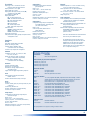
1
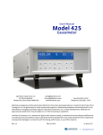
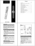
www.lakeshore.com Model 475 DSP Gaussmeter The First Gaussmeter with DSP Technology Model 475 DSP Gaussmeter The First Gaussmeter with DSP Technology Full scale ranges from 35 mG to 350 kG DC measurement resolution to 0.02 mG Basic DC accuracy of ±0.05% DC to 50 kHz frequency range (probe dependent) The First DSP Gaussmeter… Lake Shore combined the technical advantages of digital signal processing with over a decade of experience in precision magnetic field measurements to produce the first commercial digital signal processor (DSP) based Hall effect gaussmeter, the Model 475. DSP technology creates a solid foundation for accurate, stable, and repeatable field measurement while simultaneously enabling the gaussmeter to offer an unequaled set of useful measurement features. The Model 475 is intended for the most demanding DC and AC applications. In many cases it provides the functionality of two or more instruments in a field measurement system. The power of DSP technology is demonstrated in the superior performance of the Model 475 in DC, RMS, and Peak measurement modes. 15 band-pass and 3 low-pass AC filters Peak capture to 20 µs pulse widths Data buffer sampling rates to 1000 readings/s Computer interface sampling rates to 100 new readings/s Integrated electromagnet field control algorithm Standard and custom probes available DC Measurement Mode Static or slowly changing fields are measured in DC mode, where the accuracy, resolution, and stability of the Model 475 are most evident. In this mode, the gaussmeter takes advantage of the internal auto zero function and probe linearity compensation to provide its best accuracy. Measurement resolution is enhanced by advanced signal processing capability, allowing users the choice of high reading rates to 100 readings per second or high resolution to 5¾ digits. The Model 475 also features front-end amplification specifically designed to complement DSP data acquisition, providing high stability and repeatability. That, along with probe temperature compensation, makes the Model 475 the most stable gaussmeter ever produced by Lake Shore, suiting it perfectly for demanding DC measurement applications such as field mapping and field control. 2 www.lakeshore.com Lake Shore Cryotronics, Inc. (614) 891-2244 fax: (614) 818-1600 e-mail: [email protected] RMS Measurement Mode Periodic, AC fields are measured in RMS mode, which highlights the uniquely flexible filter functions of the Model 475. An overall frequency range of 1 Hz to 50 kHz is offered by the gaussmeter. Selectable band-pass and lowpass filters allow users to reject unwanted signals and improve measurement performance. The exclusive Lake Shore Digital Signal Processing algorithms also free the Model 475 from the limitations of conventional RMS conversion hardware and provide better dynamic range, resolution, and frequency response than ever before. These improvements permit meaningful RMS field measurements with broad frequency content or in noisy environments. Peak Measurement Mode Pulsed fields are measured in Peak mode, which is a natural extension of the high-speed data acquisition necessary for DSP operation. Fast instrument sample rates permit capture of positive and negative field pulses as narrow as 20 µs in width, which can be held for an unlimited length of time with no sag. This is ideal for most magnetizers and other fast pulse applications. For more moderate field changes, the Model 475 can process the captured data to create other features. The gaussmeter can be configured to follow the peak of a periodic waveform for evaluation of crest factor. The Model 475 can also be used to sample field changes at 1000 readings per second that can later be read over the interface to illustrate the shape of pulses or other waveforms. The Probe Connection The Model 475 is only half of the magnetic field measurement equation. For the complete solution, Lake Shore offers a full complement of standard and custom Hall effect probes in a variety of sizes and sensitivities – see page 6. Advanced Features The Model 475 combines hardware and firmware elements to create advanced features that facilitate automation and materials analysis. Field Control A built-in PI control algorithm turns the Model 475 into an essential building block for magnetic field control in electromagnet systems. It, along with a voltage-programmable magnet power supply, is all that is needed to control stable magnetic fields in an electromagnet at the user specified setpoint. One of the builtin analog voltage outputs drives the program input of the power supply for either bipolar or unipolar operation. High Speed Data Transfer The IEEE-488 interface can be set to send readings in binary format rather than the more common ASCII format. This reduces interface overhead, enabling real time reading rates up to 100 new readings per second. Temperature compensation is not available at the highest interface rate. Data Buffer Internal memory provides storage for 1024 field readings in a data buffer. The buffer can be filled at high speed, up to 1000 readings per second, which is as much as ten times faster than the computer interface. Stored readings can then be retrieved over interface at slower speed and processed off-line. A trigger input can be used to initiate the data log sequence. Slower sample rates can be programmed if desired. Trigger In and Trigger Out A TTL-level hardware trigger into the instrument can be used to initiate the data log sequence. A TTL-level hardware trigger out indicates when the instrument completes a reading, and can be used to synchronize other instruments in the system. An IEEE488 software-based trigger can be used like the hardware trigger in. 3 www.lakeshore.com Lake Shore Cryotronics, Inc. (614) 891-2244 fax: (614) 818-1600 e-mail: [email protected] Measurement Features The Model 475 offers a variety of features to enhance the usability and convenience of the gaussmeter. Auto Range: In addition to manual range selection, the instrument automatically chooses an appropriate range for the measured field. Auto range works in DC and AC measurement modes. Auto Probe Zero: Allows the user to zero all ranges for the selected measurement mode with the push of a key. Display Units: Field magnitude can be displayed in units of G, T, Oe, and A/m. Max/Min Hold: The instrument stores the fully processed maximum and minimum DC or RMS field value. This differs from the faster peak capture feature that operates on broadband, unprocessed field reading information. Relative Reading: Relative feature calculates the difference between a live reading and the relative setpoint to highlight deviation from a known field point. This feature can be used in DC, RMS, or Peak measurement mode. Instrument Calibration: Lake Shore recommends an annual recalibration schedule for all precision gaussmeters. Recalibrations are always available from the factory, but the Model 475 allows users to field calibrate the instrument if necessary. Recalibration requires a computer interface and precision low resistance standards of known value. Instrument Probe Features The Model 475 has several capabilities that allow the best possible measurements with Lake Shore probes. These firmwarebased features work in tandem with the probe’s calibration and programming to ensure accurate, repeatable measurements and ease of setup. Many of the features require probe characteristics that are stored in the probe connector’s nonvolatile memory. Probe Field Compensation: The Hall effect devices used in gaussmeter probes produce a near linear response in the presence of magnetic field. The small non-linearities present in each individual device can be measured and subtracted from the field reading. Model 475 probes are calibrated in this way to provide the most accurate DC readings. Probe Temperature Compensation: Hall effect devices show a slight change in sensitivity and offset with temperature. Probe sensitivity temperature effects can be measured and subtracted out of field readings. A temperature sensor in the probe tip relays real time temperature to the gaussmeter, enabling compensation. Although temperature effects contribute only a small fraction of the overall probe measurement accuracy, temperature compensation will often improve measurement and control stability. Probe Temperature Display: The gaussmeter can display the probe’s temperature in °C along with a field reading when using a probe that includes a temperature sensor. Frequency Display: When operating in RMS mode, the gaussmeter can display the frequency of the measured AC field along with a field reading (up to 20 kHz). Probe Information: The gaussmeter reads the probe information on power up or any time the probe is changed to allow hot swapping of probes. Critical probe information can be viewed on the front panel and read over the computer interface to ensure proper system configuration. Extension Cables: The complex nature of Hall effect measurements make it necessary to match extension cables to the probe when longer cables are necessary. Keeping probes and their extensions from getting mixed up can become a problem when more than one probe is in use. The Model 475 alleviates most of the hassle by allowing users to match probes to extensions in the field. Stored information can be viewed on the front panel and read over the computer interface to ensure proper mating. Hall Effect Generators (Magnetic Field Sensor): The Model 475 will operate with a discrete Hall effect generator when a suitable probe is not available. Users can program nominal sensitivity and serial number into an optional MCBL-6 blank connector to provide all gaussmeter functions except field and temperature compensation. If no sensitivity information is available, the Model 475 reverts to resistance measurement. 4 www.lakeshore.com Lake Shore Cryotronics, Inc. (614) 891-2244 fax: (614) 818-1600 e-mail: [email protected] Display and Interface Features Display The Model 475 has a two line by 20character vacuum fluorescent display. During normal operation, the display is used to report field readings and give results of other features such as max/ min or relative. The display can also be configured to show probe temperature or frequency. When setting instrument parameters, the display gives the operator meaningful prompts and feedback to simplify operation. The operator can also control display brightness. Following are four examples of the various display configurations: The display configured to show the RMS field value and frequency, and the probe temperature The display configured to show both the Maximum and Minimum DC field values Keypad The instrument has a 22-position keypad with individual keys assigned to frequently used features. Menus are reserved for less frequently used setup operations. The keypad can be locked out to prevent unintended changes of instrument setup. Alarm and Relay High and low alarms are included in the instrument. Alarm actuators include display annunciator, audible beeper, and two relays. The relays can also be controlled manually for other system needs. Voltage Output 1 The first voltage output gives access to amplified voltage signal directly from the probe. This voltage is corrected for the nominal sensitivity of the probe and provides the widest bandwidth of the three voltage outputs. In wideband AC mode, the signal can be viewed on an oscilloscope to observe the shape of AC fields. In peak mode, the output can be used to view a pulse shape or other characteristic of a momentary signal. Output 1 serves only as a diagnostic tool in DC and narrow band AC modes because modulation of the probe signal prevents a clear view of the field response. The display configured to simultaneously show the positive and negative Peak readings Line Input Assembly Serial I/O (DTE) Probe Input The display configured to show the field control setpoint and current field value, when field control is active Auxiliary I/O Voltage Output 2 The second voltage output provides a voltage proportional to measured field with the benefits of some signal processing. The output is produced by the DSP through a fast D/A converter. The output signal is updated at 40 kHz, giving good response for low to mid frequency fields. Signal quality degrades at high frequency because of the sampling rate. This voltage can be corrected for probe offset and for the nominal sensitivity of the probe. Voltage Output 3 The third voltage output provides a voltage proportional to measured field with the most signal processing of the three outputs. All probe compensation available to the display readings, including temperature compensation, can be performed on this output. The output is produced by the microprocessor through a high-resolution, 16-bit, D/A converter updated at 30 readings per second. This output can also be used for field control. Computer Interface Two computer interfaces are included with the Model 475, serial RS-232C and parallel IEEE-488. Both allow setup of all instrument parameters and read-back of measured values. The reading rate over the interface is nominally 30 readings per second but ranges from 10 to 100 readings per second are available. LabVIEW™ drivers are provided to instrument users – consult Lake Shore for availability. IEEE-488 Interface 5 www.lakeshore.com Lake Shore Cryotronics, Inc. (614) 891-2244 fax: (614) 818-1600 e-mail: [email protected] Choosing a Hall Effect Probe Proper selection of a Hall probe is probably the most difficult, and important, decision to make after choosing the Model 475. Using the improper probe could lead to less than optimal accuracy or, even worse, costly damage. The next four pages are provided to help you make an informed probe choice. If you have additional questions, contact Lake Shore and our experts can guide you through the selection process. Field measurement application is the controlling factor in probe selection. Probe characteristics, along with the parameters described below, should be considered when selecting a probe. Magnitude Typical Hall effect probes cover an operating range of 4 to 5 orders of magnitude. Operation beyond this field range requires some compromise in performance, often including higher noise or loss of resolution. Choosing the correct probe type ensures optimal performance in the desired measurement range. High Stability (HST-1 and HST-2): With a high field range of up to 350 kG (35 T), high stability probes are used when fields exceed the limit of other probe types. Their low field performance is slightly degraded with a minimum sensitivity of 50 mG (5 µT). HST probes are also inherently more temperature stable than other probes, and should be used when large temperature fluctuations are expected. They are offered in a variety of stem geometries. High Sensitivity (HSE): High sensitivity probes are the most common for generalpurpose field measurement. They operate effectively in fields up to 35 kG (3.5 T) with excellent sensitivity. At low fields, their sensitivity can be as low as 5 mG (0.5 µT). Convenient for many applications because of their relatively small active area, HSE probes are offered in the same geometries as HST probes. Ultra High Sensitivity (UHS): Low magnitude, large volume fields are most effectively measured with ultra high sensitivity probes, which have unbeatable low field resolution to 0.02 mG (2 nT). UHS probes, or gamma probes, are ideal for measuring fringe fields or variations in the earth’s field. They should never be used in fields over 30 G. UHS probes are larger than other probes and have a very large active area, making them impractical for small volume fields or tight spaces. Getting to the field is part of the challenge in selecting a probe. Field orientation dictates the most basic probe geometry choice of transverse verses axial. Other variations are also available for less common, more challenging applications. Listed below are the standard configurations for HSE and HST probes; UHS probes require special packaging that is not described here. Transverse: Transverse probes, most often rectangular in shape, measure fields normal to their stem width. They are useful for most general-purpose field measurements and are essential for work in magnet gaps. Several stem lengths and thicknesses are available as standard probes. Axial: Axial probes, usually round, measure fields normal to their end. They can also be used for general-purpose measurements, but are most commonly used to measure fields produced by solenoids. Several stem lengths and diameters are available as standard probes. Flexible: Flexible probes have a flexible portion in the middle of their stem, while the active area at the tip remains rigid and somewhat exposed. This unique feature makes them significantly more fragile than other transverse probes. Flexible probes should only be selected for narrow-gap measurement applications. Tangential: Tangential probes are transverse probes designed to measure fields parallel to and near a surface. The active area is very close to the stem tip. These probes are intended for this specific application and should not be selected for general transverse measurements. Orientation Usable Field Ranges HST-1 HST-2 35 G 35 G 350 G 350 G 3.5 kG 3.5 kG 35 kG 35 kG 350 kG HSE 3.5 G 35 G 350 G 3.5 kG 35 kG UHS 35 mG 350 mG 3.5 G 35 G 6 www.lakeshore.com Lake Shore Cryotronics, Inc. (614) 891-2244 fax: (614) 818-1600 e-mail: [email protected] Frequency Hall effect gaussmeters, like the Model 475, are equally well suited for measuring either static, DC fields or periodic, AC fields, but proper probe selection is required to achieve optimal performance. Metal Stem: Metal stem probes are the best choice for DC and low frequency AC measurements. Non-ferrous metals are used for probe stems because they provide the best protection for the delicate Hall effect sensor. Aluminum is the most common metal stem material, but brass can also be used. Metal stems do have one drawback: eddy currents are formed in them when they are placed in AC fields. These eddy currents oppose the field and cause measurement error. The error magnitude is proportional to frequency, and is most noticeable above 800 Hz. Non-metal Stem: Non-metal stems are required for higher frequency AC fields and for measuring pulse fields. Fiberglass/epoxy is a common non-metal stem material, or the Hall effect sensor can be left exposed on its ceramic substrate. This provides less protection for the sensor. Eddy currents do not limit the frequency range of these non-conductive materials, but other factors may. Please note: Neither of these probe types are suitable for direct exposure to high voltage. Gradient Probe selection would be easier if all fields were large and uniform, but most fields are limited in volume and contain gradients (changes in magnitude). Hall effect probes measure an average magnitude over their active area, making it necessary to understand the relationship between active area and field gradients. Nominal Active Area: HSE and HST probes have a nominal active area on the order of 1 mm diameter, which is useful for all but the most stringent applications. The measured field is the average of the active area, but without severe gradients, the measured value accurately represents the true field. Field mapping with standard probes is also practical if a mapping resolution of 1 mm or greater is acceptable. Small Active Area: HSE and HST probes with a smaller active area are also available from Lake Shore for measurements in severe gradients, or for high resolution mapping applications. UHS Probes: UHS probes have a very large active length, up to 3.5 in (8.9 cm). They are designed to measure very small, ambient fields with little gradient. Probe Durability All Hall effect probes are fragile. The sensor, normally located at the tip of the probe stem, must not be bent, physically shocked, or abraded. It may be tempting to choose a probe with the thinnest transverse stem or smallest diameter axial stem; however, it is always best to choose the most robust probe that fits the immediate application. For example, the HMMT-6J04-VR (aluminum stem) is less prone to damage than the HMFT-3E03-VR (flexible stem), and the HMMA-2502-VR (1/4 in diameter aluminum) is more durable than the HMNA1904-VR (3/16 in diameter fiberglass) with its exposed Hall sensor. Note: never fasten a probe stem to another object. If a probe is to be clamped, always apply the clamp to the handle. Severe field gradients are always experienced as the active sense element is moved away from a permanent magnet pole, making it important to know the distance between the active area and probe tip. The distance between probe tip and active area is specified for axial probes, but is less easily defined for transverse probes. 7 www.lakeshore.com Lake Shore Cryotronics, Inc. (614) 891-2244 fax: (614) 818-1600 e-mail: [email protected] Hall Probe Selection Guide Listed below with specifications are the commonly used probes for the Model 475 gaussmeter. Other standard probes are available. Lake Shore prides itself on making every attempt to satisfy customer requests for special probes. If you need a custom probe, contact Lake Shore for availability. All probes shown contain temperature sensors. Axial Probes L D A Active StemFrequency Probe type Corrected Operating TemperatureTemperature area material range accuracy temperaturecoefficient coefficient (% of reading) range (maximum) (maximum) zero calibration HMMA-2502-VR 2 in ±0.063 in 0.25 in dia 0.015 in Aluminum DC to 10 kHz HSE ±0.005 in HMNA-1904-VR 4 in ±0.125 in 0.187 in dia ±0.005 in 0.005 in ±0.003 in HMMA-2502-VF 2 in ±0.063 in 0.015 in Aluminum DC to 400 Hz HST-2 ±0.005 in ±0.006 in 0.25 in dia ±0.006 in HMNA-1904-VF 4 in ±0.125 in 0.187 in dia ±0.005 in 0.030 in dia (approx) 0.005 in ±0.003 in ±0.20% to 30 kG Fiberglass DC to 20 kHz epoxy Fiberglass epoxy ±0.09 G/°C ±0.015%/°C ±0.13 G/°C –0.005%/°C 0 °C to +75 °C ±0.10% to 30 kG DC to 800 Hz Transverse Probes L T W A ActiveStemFrequency Probe type Corrected Operating TemperatureTemperature area material range accuracy temperature coefficient coefficient (% of reading) range (maximum) (maximum) zero calibration HMMT-6J04-VR 4 in ±0.125 in 0.061 in max 0.180 in Aluminum DC to 800 Hz HSE ±0.005 in HMNT-4E04-VR 4 in ±0.125 in 0.045 in max 0.150 in 0.150 0.040 in dia ±0.005 in ±0.005 in (approx) HMMT-6J04-VF 4 in ±0.125 in 0.061 in max 0.180 in Aluminum DC to 400 Hz HST-2 ±0.005 in HMNT-4E04-VF 4 in ±0.125 in 0.045 in max 0.150 in ±0.005 in ±0.20% to 30 kG Fiberglass DC to 20 kHz epoxy Fiberglass epoxy ±0.09 G/°C ±0.015%/°C ±0.13 G/°C –0.005%/°C 0 °C to +75 °C ±0.10% to 30 kG DC to 800 Hz 8 www.lakeshore.com Lake Shore Cryotronics, Inc. (614) 891-2244 fax: (614) 818-1600 e-mail: [email protected] Flexible Transverse Probes W T A L S ActiveStem Frequency Probe type Corrected Operating TemperatureTemperature area material rangeaccuracy temperature coefficient coefficient (% of reading) range (maximum) (maximum) zero calibration HMFT-3E03-VR 0.135 in 0.025 in 0.125 in 3 in 0.375 in 0.040 in Flexible DC to 20 kHz HSE ±0.20% to 0 °C to max max ±0.005 in dia tubing 30 kG +75 °C HMFT-3E03-VF (approx) DC to 800 Hz HST-2 ±0.10% to 30 kG ±0.09 G/°C ±0.015%/°C ±0.13 G/°C –0.005%/°C Gamma Probes W T A LFrequency Probe type Corrected Operating TemperatureTemperature range accuracy temperature coefficient coefficient (% of reading) range (maximum) (maximum) zero calibration HMLA-5006-HJ 0.25 in ±0.03 in 0.5 in 2.2 in 5.7 in DC to 400 Hz UHS Small variations in, or low values of large volume magnetic fields (such as that of the earth or fringe fields, around large solenoids) can be measured with these ultra high sensitivity probes. Resolutions of several gammas (10-5 G) to tens of gammas are available. ±0.5% to 2 G 0 °C to +75 °C Application is optimum when fields are homogeneous over lengths greater than 1 ft. The active sensing length of the gamma probe is approximately 3.125 in. 1 mG/°C ±0.02%/°C When ordering a gamma probe, a 4065 zero gauss chamber is suggested. The standard 4060 zero gauss chamber is too small for the gamma probe. 9 www.lakeshore.com Lake Shore Cryotronics, Inc. (614) 891-2244 fax: (614) 818-1600 e-mail: [email protected] Instrument Specifications AC RMS Measurement Probe Type4¾-digit RangesResolution General Measurement (Does not include probe error, unless otherwise specified) Input type: Single Hall effect sensor Probe features: Linearity Compensation, Temperature Compensation, Auto Probe Zero, and Hot Swap Measurement features: Auto Range, Max/Min Hold, Relative Mode, and Frequency Connector: 15-pin D style DC Measurement Probe Type5¾-digit 4¾-digit 3¾-digit RangesResolutionResolutionResolution HST Probe 350 kG 35 kG 3.5 kG 350 G 35 G 000.001 kG 00.0001 kG 0.00001 kG 000.003 G 00.0030 G 000.01 kG 00.001 kG 0.0001 kG 000.02 G 00.015 G 000.1 kG 00.01 kG 0.001 kG 000.1 G 00.04 G HSE Probe 35 kG 3.5 kG 350 G 35 G 3.5 G 00.0001 kG 0.00001 kG 000.001 G 00.0003 G 0.00030 G 00.001 kG 0.0001 kG 000.01 G 00.002 G 0.0015 G 00.01 kG 0.001 kG 000.1 G 00.01 G 0.004 G UHS Probe 35 G 3.5 G 350 mG 35 mG 00.0001 G 0.00001 G 000.003 mG 00.0030 mG 00.001 G 0.0001 G 000.02 mG 00.015 mG 00.01 G 0.001 G 000.1 mG 00.04 mG Measurement resolution (RMS noise floor): Indicated by value in above table for shorted input (probe effects not included); value measured as peak-to-peak divided by 6.6 Display resolution: Indicated by number of digits in above table 3 dB bandwidth: Time constant: Maximum reading rate: 5¾-digit4¾-digit3¾-digit ResolutionResolutionResolution 1 Hz 10 Hz 100 Hz 1 s 0.1 s 0.01 s 10 rdg/s 30 rdg/s 100 to 1000 rdg/s* *Limited feature set, interface dependent DC accuracy: ±0.05% of reading ±0.005% of range DC temperature coefficient: ±0.01% of reading ±0.003% of range/°C HST Probe 350 kG 35 kG 3.5 kG 350 G 35 G 000.01 kG 00.001 kG 0.0002 kG 000.02 G 00.020 G HSE Probe 35 kG 3.5 kG 350 G 35 G 3.5 G 00.001 kG 0.0001 kG 000.02 G 00.002 G 0.0020 G UHS Probe 35 G 3.5 G 350 mG 35 mG 00.001 G 0.0002 G 000.02 mG 00.020 mG Measurement resolution (RMS noise floor): Indicated by value in above table for shorted input Display resolution: Indicated by number of digits in above table Max reading rate: 30 rdgs/s (100 to 1000 rdgs/s; limited feature set, interface dependent) AC accuracy: ±1% of reading AC frequency range: 1 Hz to 1000 Hz, narrow band mode‚ 50 Hz to 20 kHz, wide band mode AC band limiting (filters): 18 user selected frequencies of 3 low-pass or 15 band-pass Peak Measurement Probe Type4¾-digit RangesResolution HST Probe 350 kG 35 kG 3.5 kG 350 G 35 G 000.01 kG 00.001 kG 0.0002 kG 000.02 G 00.020 G HSE Probe 35 kG 3.5 kG 350 G 35 G 3.5 G 00.001 kG 0.0001 kG 000.02 G 00.002 G 0.0020 G UHS Probe 35 G 3.5 G 350 mG 35 mG 00.001 G 0.0002 G 000.02 mG 00.020 mG Measurement resolution (RMS noise floor): Indicated by value in above table for periodic mode and shorted input Display resolution: Indicated by number of digits in above table Max reading rate (periodic mode): 30 rdgs/s (100 to 1000 rdgs/s; limited feature set, interface dependent) Peak accuracy: ±2% of reading (20 µs or longer) Peak frequency range (periodic mode): 50 Hz to 5 kHz Peak frequency range (pulse mode): 5 Hz to 50 kHz 10 www.lakeshore.com Lake Shore Cryotronics, Inc. (614) 891-2244 fax: (614) 818-1600 e-mail: [email protected] Front Panel Display type: 2 line × 20 character, vacuum fluorescent with 9 mm high characters Display resolution: To ±5¾ digits Display update rate: 5 rdgs/s Display units: Gauss (G), Tesla (T), Oersted (Oe), and Ampere per meter (A/m) Units multipliers: µ, m, k, M Display annunciators: DC – DC measurement mode RMS – AC RMS measurement mode PK – Peak measurement mode MX – Max Hold value MN – Min Hold value SP – Relative setpoint value CSP – Field Control setpoint value LED annunciators: Relative – Relative reading mode Alarm – Alarm active Remote – Remote IEEE-488 operation Keypad: 22 full travel keys Front panel features: Display prompts, front panel lockout, and brightness control Interfaces Voltage Output 2 Configuration: Voltage output of field value, generated by DAC Range: ±5 V Scale: ±3.5 V = ±FS on selected range Resolution: 16-bit, 0.15 mV Update Rate: 40,000 updates per s Accuracy: ±10 mV Noise: ±0.3 mV Minimum load resistance: 1 kΩ (short-circuit protected) Connector: In 25-pin I/O connector Voltage Output 3 Configuration: Voltage output of compensated DC or RMS field value, generated by DAC (also used for field control) Range: ±10 V Scale: User specified (defaults same as Voltage Output 2) Resolution: 16-bit, 0.3 mV Update rate: 30 updates per s Accuracy: ±2.5 mV Noise: ±0.3 mV Minimum load resistance: 1 kΩ (short-circuit protected) Connector: In 25-pin I/O connector General Ambient temperature: 15 °C to 35 °C at rated accuracy, 5 °C to 40 °C with reduced accuracy Power requirement: 100, 120, 220, and 240 VAC (+5%, -10%), 50 Hz or 60 Hz, 20 W Size: 217 mm W × 90 mm H × 317 mm D, half rack (8.5 × 3.5 × 12.5 in) Weight: 3 kg (6.6 lb) Probes & Extensions Probe compatibility: Full line of standard probes available – custom probes also available (not compatible with Model 450/421 probes) Hall sensor compatibility: Front panel programmable sensitivity and serial number for user supplied Hall sensor Extension cable compatibility: Probe extension cables with EEPROM available from 25 ft to 100 ft (extension cables can be matched to probes in the field) Lake Shore calibrated extension cables maintain the same accuracy as the Model 475 probe. The uncalibrated version involves the operator loading the matching probe data file into the cable PROM directly from the Model 475 front panel. Additional errors caused by the uncalibrated extension cables are ±0.1% of field reading error and 1 °C temperature reading error. RS-232C Baud: 9600, 19200, 38400, and 57600 Update rate: 30 rdgs/s (ASCII) Software support: LabVIEW™ driver (consult Lake Shore for availability) Connector: 9-pin D-style, DTE configuration IEEE-488.2 Capabilities: SH1, AH1, T5, L4, SR1, RL1, PP0, DC1, DT1, C0, and E1 Update rate: 30 rdgs/s (ASCII), to 100 rdgs/s (binary, no temperature compensation) Software support: LabVIEW™ driver (consult Lake Shore for availability) Data Buffer Capacity: 1024 field readings Reading rate: 1 to 1000 rdgs/s Data transfer: Through computer interface after data is logged Trigger: Hardware trigger to begin data log sequence Alarm Settings: High/low setpoint, Inside/Outside, Audible, and Sort Actuators: LED annunciator, beeper, and relays Relays Number: 2 Contacts: Normally open (NO), normally closed (NC), and common (C) Contact rating: 30 VDC at 2 A Operation: Follows alarm or operated manually Connector: In 25-pin I/O connector Voltage output 1 Configuration: Real-time analog voltage output of wide band AC signal Range: ±3.5 V Scale: ±3.5 V = ±FS on selected range Frequency response: 1 Hz to 40 kHz (wide band AC) Accuracy: Probe dependent Noise: ±1.0 mV Minimum load resistance: 1 kΩ (short-circuit protected) Connector: In 25-pin I/O connector Ordering Information Part Number 475 Description Model 475 DSP gaussmeter Please indicate your power/cord configuration: 100 VAC, U.S. power cord 120 VAC, U.S. power cord 220 VAC, European power cord 240 VAC, European power cord Accessories Included 106-253 I/O mating connector 4060 Zero gauss chamber MAN-475 Model 475 gaussmeter user manual Accessories Available 4005 RM-½ RM-2 HMCBL-6 HMPEC-10 HMPEC-10-U HMPEC-25 HMPEC-25-U HMPEC-50 HMPEC-50-U HMPEC-100 HMPEC-100-U 1 m (3.3 ft) long IEEE-488 (GPIB) computer interface cable assembly – includes extender required for simultaneous use of IEEE cable and auxiliary I/O connector Rack mount kit for one ½-rack gaussmeter in 483 mm (19 in) rack Rack mount kit for two ½-rack gaussmeter in 483 mm (19 in) rack User programmable cable with EEPROM (6 ft) Probe extension cable with EEPROM (10 ft), calibrated Probe extension cable with EEPROM (10 ft), uncalibrated Probe extension cable with EEPROM (25 ft), calibrated Probe extension cable with EEPROM (25 ft), uncalibrated Probe extension cable with EEPROM (50 ft), calibrated Probe extension cable with EEPROM (50 ft), uncalibrated Probe extension cable with EEPROM (100 ft), calibrated Probe extension cable with EEPROM (100 ft), uncalibrated (Extension cables must be matched to probes) Calibration Service CAL-475 CAL-475DATA Instrument calibration Instrument calibration with report and data All specifications are subject to change without notice 11 www.lakeshore.com Lake Shore Cryotronics, Inc. (614) 891-2244 fax: (614) 818-1600 e-mail: [email protected] Lake Shore Cryotronics, Inc. 575 McCorkle Boulevard Westerville, OH 43082 USA Tel 614-891-2244 Fax 614-818-1600 e-mail [email protected] www.lakeshore.com Established in 1968, Lake Shore Cryotronics, Inc. is an international leader in developing innovative measurement and control solutions. Founded by Dr. John M. Swartz, a former professor of electrical engineering at the Ohio State University, and his brother David, Lake Shore produces equipment for the measurement of cryogenic temperatures, magnetic fields, and the characterization of the physical properties of materials in temperature and magnetic environments.