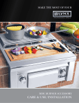
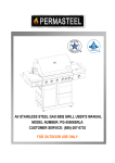
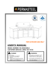
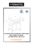
1
Professional Models Premier Models L-30/42/54(F)R LSB1&2, LCB1&2 CS 30 (F) LDR 21/30/42//54 LIJ 30/42/54 LBQ-27/36/48(F)(R)E LIJ-27/36/48 LBQSB1&2 LBQCB1&2 LDR-18/27/36/48 Rev. 06/03 A MESSAGE TO OUR CUSTOMERS: Thank you for choosing LYNX as your new gas grill. With proper use and care, we’re confident that this Grill will provide years of trouble-free service. Careful attention has been put into every detail of this grill and, by reading this entire manual before your first use, you will be assured maximum performance. This manual also contains important safety tips and some hints for better grilling. Please keep it in a convenient location so it will be available to answer any future questions. Should your LYNX Grill change ownership, please make sure that the new owner receives this manual. We love to hear from our customers. Please feel free to contact us with any questions or problems, or to share a new recipe. Please include the model number of your grill in your correspondence. Thanks again for your purchase. Enjoy! Lynx Professional Grills 6023-25 Bandini Blvd., Commerce, CA 90040 Service: (888) Buy-Lynx Tel: (323) 838-1770 Fax: (323) 838-1782 www.lynxprofessionalgrills.com FOR OUTDOOR USE ONLY Improper installation, adjustment, alteration, service or maintenance, can cause property damage, injury or death. Read this manual thoroughly before installation, use or servicing of this equipment. NOTE TO INSTALLER: This manual must remain with grill. Check your local building codes for proper method of installation. In the absence of local codes, this unit should be installed in accordance with National Fuel Gas Code No. Z223.1-1988 USA or CAN/CGA-B149.1/.2 Natural Gas/Propane Code.(Canada) latest edition or the National Electrical Code ANSI/NFPA No. 70 or the Canadian Electrical Code CSA C22.1,1990 or latest edition. UNPACKING: CHECK THAT THE CONTAINER IS UPRIGHT BEFORE REMOVING FROM CARTON. CHECK THE UNIT FOR VISIBLE DAMAGE. IF DAMAGE HAS OCCURRED, DO NOT REFUSE SHIPMENT; CONTACT THE FREIGHT CARRIER AND FILE APPROPRIATE FREIGHT CLAIM. See page 24 for more information. Rev. 06/03 Table of Contents Safety Practices & Precautions..................................................................................... 3 Leak Testing......................................................................................................................... 6 Locating the Grill................................................................................................................. 7 Utility Requirements............................................................................................................ 9 Features and Identification ................................................................................................ 13 Lighting Instructions........................................................................................................... 16 Match Lighting..................................................................................................................... 17 Burner Adjustments............................................................................................................ 18 Using the Grill...................................................................................................................... 19 Using the Smoker................................................................................................................ 19 Using the Rotisserie............................................................................................................ 21 Burner Removal and Cleaning........................................................................................... 22 Service.................................................................................................................................. 24 Warranty................................................................................................................................ 25 SAFETY INSTRUCTIONS WARNING! Read this manual carefully and completely before using your grill to reduce the risk of fire, burn hazard or other injury, making sure of proper installation and servicing. 2 Rev. 06/03 Safety Practices & Precautions FOR YOUR SAFETY: 1. Never use natural gas in a unit designed for liquid propane or visa versa. 2. If you smell gas: A. Shut off gas to the appliance. B. Extinguish any open flames. C. Open lid. D. If odor continues, immediately call your gas supplier. 3. DO NOT store or use gasoline or other flammable vapors and liquids in the vicinity of this or any other appliance. 4. Whenever the grill burners have been removed, follow the installation instructions. 5. NEVER LEAVE THE GRILL UNATTENDED WHILE COOKING. 6. California Proposition 65 — WARNING! The burning of gas cooking fuel generates some by-products, which are on the list of substances, which are known by the State of California to cause cancer or reproductive harm. California law requires businesses to warn customers of potential exposure to such substances. To minimize exposure to the substances, always operate this unit according to the use and care instructions found in this manual. Be certain to provide adequate ventilation when cooking. California Proposition 65 lists “Silica, crystalline” which is used in one of the components of the IR burner, as an agent known to the state of California to cause cancer. 7. Do not repair or replace any part of the grill unless specifically recommended in this manual. All other service should be performed by a qualified technician. 8. Gas grills are not design-certified for and are not to be installed in or on recreational vehicles, portable trailers, boats or any other moving installation. 9. Children should not be left alone or unattended in an area where a grill is located. Place your grill well away from areas where children play. Do not store items that may interest children in or around the grill, in the cart or in the masonry enclosure. When in use, portions of the grill are hot enough to cause severe burns. 10. Avoid wearing loose-fitting garments or long sleeves while using the grill. Never touch the grill racks, hood or immediate surrounding metal surfaces with your bare hands as these areas become extremely hot during use and could cause burns. Use an insulated glove or mitt when opening and operating the grill. Open grill lid slowly to allow heat and smoke to escape before fully opening. Never lean over hot grill surface or look directly into the grill when attempting to light. The grill hood must be fully opened when lighting. Rev. 06/03 3 Safety Practices & Precautions 11. Have an ABC Fire Extinguisher accessible — never attempt to extinguish a grease fire with water or other liquids. 12. Insure that the gas supply hose is free of kinks and at least 3” away from hot surfaces. 13. Do not heat unopened food containers as a build-up of pressure may cause the container to burst. 14. Never store additional or empty propane cylinders in the grill cabinet or around the grill. Do not store propane cylinders indoors or on their sides. Never use dented, rusty or damaged propane cylinders. 15. Do not use aluminum foil to line grill racks or drip pans. This will alter combustion airflow or trap excessive heat in the control area. This can result in melted knobs and rotary igniters. 16. If the grill is installed by a professional installer or technician, be sure that he shows you where your gas supply shut-off is located. All gas lines must have a shut-off that is readily and easily accessible. If you smell gas, check for gas leaks immediately. Check only with a soap and water solution. Never check for gas leaks with an open flame. 17. Never use charcoal in the grill. Never operate the grill in a windy area. If windy conditions exist, install a suitable windbreak. 18. Be aware that cooking excessively fatty meats and other such products will cause flareups. Internal fires or damage caused by flare-ups or the grill being left unattended while cooking, are not the responsibility of LYNX and any resulting damage is not covered under the terms and conditions of our Warranty. 19. Never grill without the drip pan in place. The drip pan must be pushed all the way to the back of the grill. Without the drip pan in place, hot grease could leak downward and produce a fire or explosion hazard. 20. Store your grill in a well-ventilated area. Remove the LP cylinder, if so equipped, and store it outdoors in a well-ventilated area away from heat and away from where children may tamper with it. 21. Always adhere to the required clearances from combustibles as detailed. The grill is designed for use outdoors only. Never operate in a garage, building, shed, breezeway or other enclosed area. 22. Grease is extremely flammable. Let hot grease cool down before attempting to handle or dispose of it. The drip tray should be cleaned of grease on a regular basis. 23. Keep any electrical supply cord away from any heated surface. Electrical cords should be 4 Rev. 06/03 Safety Practices & Precautions placed away from walkways to avoid tripping hazard. 24. Do not use the grill until a leak check has been performed (see page 6). 25. Do not move grill while in use or hot. 26. Never place more than 30 pounds on a side shelf. Do not lean on shelves. 27. Do not operate grill under the influence of alcohol or drugs. 28. If any burner does not light or goes out during operation, turn off all gas control knobs with hood open and wait five (5) minutes before attempting to re-light. Never connect any unregulated gas supply to the grill. The regulator with hose Type 1 connection has the following safety features: The system will not allow gas to flow until a positive connection has been made. The system has a thermal element that will shutoff the flow of gas between 115 and 150ºC (240 and 300ºF). The system has a flow limiting device which, when activated, will restrict the flow of gas to 10 cubic feet per hour. NOTE:The cylinder control valve must be turned off before any connection is made or removed. NEVER USE GRILL WITHOUT LEAK TEST ING THIS CONNECTION. Should the large black thermally sensitive coupling nut be exposed to temperatures above 115-150ºC it will soften and allow the regulator probe to disengage from the cylinder valve, thereby shutting off the flow of gas. Should this occur, do not attempt to reconnect the nut. Remove the entire regulator assembly and replace it with a new one. The cause of the excessive heat should be determined and corrected before operating your grill again. The regulator probe also contains a flow-sensing element, which will limit the flow of gas to the regulator to a manageable amount (10 cubic feet/hour) in the event of a hose or regula tor rupture. If it is evident that the flow control device has activated the cause of the excess flow should be determined and correct ed before using your grill again. NOTE: Improper lighting procedures can cause the flow control to activate, resulting in reduced heat out put. If this is suspected, to reset flow control, shut off all burner controls and cylinder valve, wait 30 sec onds, then turn cylinder valve on extremely slowly wait five (5) seconds and turn burner valve on and light. Rev. 06/03 5 Leak Testing LP Gas Leak Check Natural Gas Leak Check 90°x1/2” Street Elbow Check points Check hose for signs of abrasion cracks and leaks 1/2” NPT Nipple Regulator Adapter (supplied by others) (supplied by others) LP Tank Shut-off Valve (supplied by others) DANGER: To prevent fire or explosion hazard: NO SMOKING. DO NOT use or permit sources of ignition in the area while doing a leak test. Perform leak tests outdoors only. Never perform a leak test with fire or flame. HOW TO PERFORM A LEAK TEST: 1. 2. 3. 4. 5. Create a soapy solution of equal parts mild dishwashing detergent and water. Confirm that all control knobs are in the off position. Turn on fuel supply. Turn cylinder valve knob counter clockwise (right to left) one rotation. Apply soap solution generously by paint brush or squirt bottle on all connections and fittings. If “growing” bubbles appear on any of the connection points, then you have detected a gas leak. IMMEDIATELY close the LP cylinder valve by turning the handle clockwise. FIXING A FUEL LEAK: If you detect a leak: 1. 2. 3. Push in and turn on control knobs to release pressure in hose, then turn the control knobs back to off. Wash off soapy solutions with cold water and towel dry. Stop a leak by tightening the loose joint, or by replacing the faulty part with a replacement part recommended by the manufacturer. DO NOT attempt to repair the cylinder valve if it should become damaged; the cylinder MUST BE REPLACED. 6 Rev. 06/03 Locating the Grill LOCATION: When selecting a suitable location, take into account concerns such as exposure to wind and traffic paths. Try to keep all gas supply lines as short as possible. Never locate the grill in a building garage, shed or other such enclosed area. A carpenter’s “spirit level” should be used to assure that the unit is level both front-to-back and side-to-side. If it is not level, burner combustion may be erratic. The unit may not function efficiently. If the floor is uneven or has a decided slope, re-leveling may be required after each moving of a freestanding unit. BUILT-IN INSTALLATIONS: The LYNX Built-In Grill is designed for easy installation into masonry enclosures. For non-combustible applications the grill drops into the opening shown in cutout detail drawing and hangs from its counter top trim. A deck is not required to support it from the bottom. When using the insulated jacket in a combustible enclosure, the jacket must be supported from the bottom by a ledge on each side or a full deck beneath the jacket. Review the detailed drawing and pay special attention to the provisions shown for gas line hook-up. It is recommended that the enclosure have ventilation holes to prevent gas build-up in the event of a leak. The deck ledges and counter should be flat and level. If your grill is equipped with a rotisserie, electrical service should be provided (on the Left Side of most models). CLEARANCE TO NON-COMBUSTIBLE CONSTRUCTION: A minimum of 2” clearance on Premier Models 27/36/48 from the back of the grill. Professional Models 30/42/48 and 54 require a minimum of 4” for the purpose of opening the hood. The grill exhausts combustion products and cooking greases to the back. Never locate the grill where this exhaust will be difficult to clean. CLEARANCE TO COMBUSTIBLE CONSTRUCTION: A minimum of 12” must be maintained between the grill sides and back, and any combustible construction. A 12” minimum clearance must also be maintained above and below the cooking surface and in any combustible construction. Warning: Installing this product into a combustible enclosure without an insulated jacked could result in fire, property damage and personal injury. If the grill is to be placed into a combustible enclosure, an approved insulated jacket is necessary and is available from your LYNX dealer. Use only a LYNX insulated jacket as it has been designed and tested specifically for your Grill. Refer to page 8 for cutout dimensions. A minimum of 6” of clearance is needed on each side of the grill for the motor and skewer. OVERHEAD CLEARANCE: Do not build your LYNX Grill directly below unprotected overhead combustible construction. Rev. 06/03 7 12 Professional Series 2" 0 or 2" Square Holes For Manifold Connection " Recommended Minimum 12" 1/8 Clearance 30, 42,48, 54 4" Minimum D B Transformer (Professional Models) C G Side Burner A E F Grill or insulating Jacket /8 11 J Premier Series Clearance 27, 36 2" Minimum 19" Cocktail Pro 1/2 NPT Gas Connection n. i "M Access Doors 35 1/2" Max. I Drawer Opening Note: Cocktail Pro should have an open bottom for plumbing and drain access. H *CS-18, CS-30 and LUD cutouts are used for both Premier and Professional Series. 1/2 NPT Gas Connection Professional Series Dimensions Model L-30 L-42 L-48 L-54 LIJ-30 LIJ-42 LIJ-48 LIJ-54 LSB-1 LSB-2 LSB-1-48 LSB-2-48 CS-18 CS-30 LDR-30 LDR-42 LDR-48 LDR-54 LUD A N/A N/A N/A N/A N/A N/A N/A N/A N/A N/A N/A N/A 18 29 N/A N/A N/A N/A N/A B 29 41 47 53 36 48 54 60 N/A N/A N/A N/A N/A N/A N/A N/A N/A N/A N/A C 2 1/4 2 1/4 2 1/4 2 1/4 5 5 5 5 2 1/4 2 1/4 2 1/4 2 1/4 N/A N/A N/A N/A N/A N/A N/A Model A B C D LBQ-27 LBQ-36 LIJ-27 LIJ-36 SB-1 SB-2 LDR-18 LDR-27 LDR-36 N/A 26 35 33 42 2 1/4 2 1/4 5 5 2 1/4 2 1/4 22 22 24 24 22 1/2 22 1/2 D 24 1/2 24 1/2 22 24 1/2 26 1/2 26 1/2 24 26 1/2 22 1/2 22 1/2 22 1/2 22 1/2 22 1/2 22 3/4 N/A N/A N/A N/A N/A E 3 1/2 3 1/2 3 1/2 3 1/2 4 1/2 4 1/2 4 1/2 4 1/2 3 1/2 3 1/2 3 1/2 3 1/2 N/A N/A N/A N/A N/A N/A N/A F 2 2 2 2 3 3 3 3 2 2 2 2 N/A N/A N/A N/A N/A N/A N/A G 10 7/8 10 7/8 10 7/8 10 7/8 11 5/8 11 5/8 11 5/8 11 5/8 10 5/8 10 5/8 10 5/8 10 5/8 10 5/8 10 5/8 N/A N/A N/A N/A N/A H N/A N/A N/A N/A N/A N/A N/A N/A N/A N/A N/A N/A N/A N/A 28 1/4 40 1/4 46 1/4 52 1/4 N/A I N/A N/A N/A N/A N/A N/A N/A N/A N/A N/A N/A N/A N/A N/A N/A N/A N/A N/A 12 1/8 J N/A N/A N/A N/A N/A N/A N/A N/A N/A N/A N/A N/A N/A N/A N/A N/A N/A N/A 19 1/4 Premier Series Dimensions N/A N/A N/A N/A N/A 3 3 4 4 3 3 E F G H I J 1/2 1/2 1/2 1/2 1/2 1/2 2 2 3 3 2 2 10 7/8 10 7/8 11 5/8 11 5/8 10 5/8 10 5/8 N/A N/A N/A N/A N/A N/A N/A N/A N/A N/A N/A N/A N/A N/A 16 1/4 25 1/4 34 1/4 N/A N/A N/A N/A N/A N/A N/A N/A N/A N/A N/A N/A N/A N/A N/A N/A N/A N/A N/A N/A N/A N/A N/A N/A N/A N/A N/A N/A N/A N/A N/A N/A N/A 8 Rev. 06/03 Utility Requirements PROPANE (LP) or NATURAL GAS ONLY Your grill is equipped to use either propane (LP) or natural gas (NAT). It is very important that the grill rating plate agrees with that of the gas supply. The rating plate is located either under the drip tray, the heat shield behind the front panel (remove smoker tray) or on the inside left cabinet wall (most freestanding grills). Do not attempt to operate the grill on any gas other than what the grill is orificed for and what the regulator is set for. The regulator cap must be turned over to change gas types. For connection to an LP tank, the grill comes equipped with a high capacity LP Regulator/hose assembly (Type 1). Never connect an unregulated gas line to the grill. Cap L.P. Gas Hook Up (Type 1 or QCC1 regulator): Appliance Regulator Grills orificed for use with L.P. gas come equipped with an LP hose/regulator assembly for connection to a standard 20 lb. L.P. cylinder (Type 1). The L.P. tank is not included. Connection: 1/2" NPT male with a 3/8" Flare adapter. LP Hose and fittings are included. Operating pressure: 10.0"W.C. Connect the 3/8” flare end of the L.P. hose to the brass adapter on the manifold Connect the Regulator to the tank (with the tank valve fully closed). Although the flow of gas is stopped when the Type 1 system is disconnected, you should always turn the L.P. tank main valve off after each use and during transport of the tank or unit. Insert the regulator inlet into the tank valve and turn to the black coupler clockwise until the coupler is tight. Elbow1/2”x Do not overtighten the coupler. 3/8 Flare Type 1 LP To purge gas line: Make sure all controls are in the OFF position. Regulator Turn the main tank valve on SLOWLY and turn one burner control valve on the unit to the “light” position (DO NOT LITE GRILL). Leave control ON for about 20 seconds to allow the air in the system to purge. Wait 10 minutes before attempting to light the burners. Do not attempt lighting the grill within 10 minutes after purging! To disconnect the coupler, first make sure the main tank valve is turned off. Grasp the coupler and turn counter clockwise. The inlet will then disengage, remove the inlet from the tank valve opening if it has not already done so when it disengaged. Your local L.P. filling station should be equipped with the proper equipment to fill your tank. If trading your tank in, always ensure to obtain only Type 1 20lb cylinders with an overfill protection device. Rev. 06/03 9 Utility Requirements L.P. Tank Requirements: A dented or rusty L.P. tank may be hazardous and should be checked by your L.P. supplier. Never use a cylinder with a damaged valve. Always check for leaks after every L.P. tank change. The L.P. gas cylinder must be constructed and marked in accordance with the specifications for L.P. gas cylinders of the U.S. Department of Transportation (DOT) and designed for use with a Type 1 system only. Do not change the regulator/hose assembly from that supplied with the unit or attempt to use a 5LP-A equipped regulator/hose assembly with a standard 510 POL tank/valve assembly. The cylinder must be provided with a shut off valve terminating in an L.P. gas supply cylinder valve outlet specified, as applicable, for connection Type 1. If the appliance is stored indoors the cylinder must be disconnected and removed from the appliance. Cylinders must be stored outdoors in a well-ventilated area out of the reach of children. Natural Gas Installations: The installation of the grill must conform with local codes or, in the absence of local codes, to the National Fuel Gas Code ANSI Z223.1-1988 or latest edition. If installed in Canada, installation must be in accordance with Gas Code CAN/CGA B149, 1 or .2 and local codes. The gas supply line must be sized to accommodate all the gas-fired equipment that may be connected to that supply, i.e. total BTU output to be consumed, needs to be determined so as to calculate what size diameter pipe is needed, for the total length of pipe from the gas main (at house) to grill hook-up. If the gas line is too small, the grill will not function properly. An installer-supplied gas shut-off valve must be installed in an easily accessible location. All installer-supplied parts must conform to local codes with the National Electrical Code, ANSI/NFPA 70-1990 and the National Fuel Gas Code, ANSI Z223.1-1988. The appliance and its individual shut off valve must be disconnected from the gas supply piping system during any pressure testing of that system at test pressures above 1/2” PSIG (3.5KPA). The appliance must be isolated from the gas supply piping system by closing its individual manual shut off during any pressure testing. Do not apply threading compound to the first two pipe threads as to avoid clogging of the burner valves and orifice. Do not put sealant on any male end of flare fittings. 10 Rev. 06/03 Utility Requirements Electrical Requirements for Built-in Units: For Rotisserie Models, installation should include an outdoor 120VAC 15A GFI located adjacent to the Rotisserie Motor. Double check what side your motor will mount to and be sure to place the outlet on that side of the Grill. Do not locate motor or outlet on the same side as a Side Burner unless a minimum of 12” clearance is provided. Built-in Professional Models Only: Power should be provided within the enclosure for the Halogen Lighting Transformer Box. This power source may be a junction box (for hardwiring) or a GFI for connection with extension cord (not supplied). The Transformer Box reduces the voltage to 12Volts for the lights. A qualified electrician can install a GFI outlet and/or hardwire the transformer box inside the enclosure. Electrical Requirements for Professional Freestanding Units: The cart includes receptacles at the back for connecting Rotis Motor (convenience outlet) and a Power In receptacle for connecting to GFI Plug. The connection provides power to a transformer (12volts) for the Halogen Lights. See drawing for connection. Note: Moving the rotisserie motor to the opposite side will prevent it from reaching the convenience outlet. Convenience Outlet Rotis Motor Cord Plug female end of extension cord (not supplied) into cart as shown. GFI Outlet Plug male end into your GFI Outlet. Rev. 06/03 11 Utility Requirements Electrical connections must be made by a qualified electrician in conformance with local codes or, in the absence of local codes with the National Electrical Code. Instructions for Built-in Grills: Electrical Connections Lynx Professional Grills fitted with Halogen Lights are shipped with an extra outlet box for connection to a standard 120vac GFI outlet. This connection may be: A) hard wired to an outdoor GFCI junction box (requires an installer supplied 3 prong plug with pigtail leads) or B) plugged directly into an existing GFCI Protected outlet with a 3 pronged extension cord suitable for use in outdoor applications (not included). When locating the box ensure that adequate space is provided between the grill and that the cables will not come into contact with the ground or any sharp edges The Convenience Outlet provides a power source for accessories when the box is energized The Power Feed Cable supplies 120vac household power to the Grill for the light only. The grill will function normally without power to the light. The Power In receptacle is used to supply power to the box that energizes the Convenience Outlet and the Grill Light. 12 Rev. 06/03 Features and Identification 30” Professional Light Switch 42” Professional Rotis Grill Smoker Grill Smoker Ignition Rotis Grill Smoker Grill Tray Switch Tray Safety Valve Grill Smoker Light Switch 54” Professional Light Switch Ignition Rotis Grill Switch Grill Smoker 27” Premier Utility Drawer Front Rear Side Burner Safety Valve 36” Premier Ignition Rotis Grill Smoker Grill and Ignition Rotis Grill Smoker Grill and Smoker Switch Tray Smoker Switch Tray 48” Premier* Safety Valve Ignition Rotis Grill Smoker Switch Tray Grill and Smoker Grill Rotis * 48” Premier has (2) Rotis Burners and (2) Smoker Trays Rev. 06/03 13 Grill Features and Identification Replacing Ignition Batteries Professional Models Premier Models 9 volt battery Battery Cover Logo plate 9 volt battery Professional Models: Premier Models: The battery is located behind the Battery Covers found on the sides of the control panel. Note: Some models use (2) batteries with one on each side. To change batteries: Remove the snap in Battery Cover as shown. Replace with new 9volt battery. The battery is located behind the Logo Plate. To change batteries: Pull the Logo Plate outward as shown. Glass Light Cover To change light bulbs: Remove the Glass Light Cover by grasping the edge of glass and pry it off. It may be necessary to remove one screw. Pull the old bulb straight out from socket, do not twist. Replace with 12v, 5 watt bulb of similar pin type socket design and always avoid touching the Use glass of new bulbs. only pin style 12v, 5 watt bulbs 14 Rev. 06/03 Features and Identification Flip-over Shelves Cart Features (Professional Models only) Locking Casters Lift-Off Doors Briquette Placement Note: All Models Place Briquettes over each round hole as shown and ensure they are positioned between the raised slots in the tray Note: Premier Series Only: Briquette tray used under smoker does not utilitze 2 briquettes in the front middle directly under smoke tray, use a total of 26 briquettes only (See Picture Below). Briquettes Briquettes Tray Briquettes Tray Assembled Rev. 06/03 Premier Models: 28 briquettes per tray Professional 30”: 35 briquettes per tray Professional 42”: 28 briquettes middle tray 35 briquettes L & R trays 15 Lighting Instructions WARNING! Before lighting: Prior to using grill please remove tie down wires on brass burners. Inspect the gas supply piping or hose prior to turning the gas "on". If there is evidence of cuts wear, or abrasion, it must be replaced prior to use. The replacement pressure regulators and hose assembly must be the type specified by the manufacturer. Do not use the grill if the odor of gas is present. The pressure regulator and hose assembly supplied with the unit must be used. If the unit is L.P., screw the regulator into the tank and leak check the hose and regulator connections with a soap and water solution before operating the grill. Turn all knobs to "off " then SLOWLY turn on the gas supply valve. Always keep your face and body as far away from the grill as possible when lighting. Do not attempt to "Light" the grill if the odor of gas is present. Call for service. Always wait at least 5 minutes before relighting a hot grill. Grill Burners Rotis Burner (not all models) To Light: Open the lid, push and hold the ignition button for 5 seconds. You should hear a “clicking” sound. If not, turn all knobs to “OFF” and check ignition battery (see page 12). To Light: Open the lid, push and hold the Safety Valve ignition button for 5 seconds. You Button should hear a “clicking” sound. If not, turn all knobs to “OFF” and check ignition battery Control (see page 12). Knob Turn burner control knob to light. If the burner does not light in 4 seconds, turn knobs to "OFF". Control Knob Ignition Button Turn the Rotis control knob to “lite”. Hold the safety valve button in for about 4 seconds then Press and hold the igniter button. This is the only burner on the grill with a safety valve. Once lit, turn control knob to desired setting. If the burner does not light within 4 seconds, release the safety valve button and turn the control knob to “OFF”. Once lit, the rotis burner should reach cooking temperatures in about 1 minute. The orange/red glow will even out in about 5 minutes. If burners will not light after several attempts, see the instructions on match lighting on next page. Always wait at least 5 minutes before relighting a hot burner! 16 Rev. 06/03 Match Lighting Match Lighting: If burners will not light after several attempts, the burners can be match lit. If you’ve just attempted to light the burner with the igniter, allow 5 minutes for any accumulated gas to dissipate. Grill Burners: Make sure all knobs are in the OFF position. Keep your face as far away from the grill as possible. With the Lid open, pass a lit, long stemmed match to the ports of the burner. Push and turn the corresponding control knob of the Burner Ports Grill Burner burner to “Lite”. If the burner does not light in 4 seconds, turn the knob off and wait 5 minutes before attempting again. Rotis Burner Burner Tiles Rotis Burner: Make sure all knobs are in the OFF position. With the Lid open pass a lit, long stemmed match to the burner tiles of the Infra-Red burner. Push and turn the Rotis control knob to “Lite” then press and hold the safety valve button. If the burner does not light in 4 seconds, turn the knob off and wait 5 minutes before attempting again. Thermocouple If the burner stays lit only while holding the safety button, it may be adjusted (after it has cooled) as shown. Keep cool Rev. 06/03 17 Keep end close to tiles Burner Adjustments Burner Air Adjustment: Each grill burner is tested and adjusted at the factory prior to shipment; however, variations in the local gas supply or a conversion from one gas to another may make it necessary to adjust the burners. The flames of the Grill burners should be visually checked and compared to that of the drawing below. Flames should be blue and stable with no yellow tips, excessive noise or lifting. If any of these conditions exist, check if the air shutter or burner ports are blocked by dirt, debris, spider webs, etc. Proceed with air shutter adjustment. The amount of air which enters a burner is governed by a sheet metal cup or disk at the inlet of the burner called an air shutter. It is locked in place by a set screw which must be loosened prior to lighting the burner for adjustment. To Adjust: Set Screw 1. Be extremely careful as the burner may be very hot. 2. If the flame is yellow, indicating insufficient air, turn the air shutter counterclockwise to allow more air to the burner. 3. If the flame is noisy and tends to lift away from the burner, indicating too much air, turn the air shutter clockwise. 4. Once adjusted turn the burner off and install the briquette trays and grill racks. Air Shutter Bezel Low Setting Adjustments: The valves on the grill feature an adjustable low setting. Due to fluctuations in gas pressure, heating value or gas conversion, you may feel it necessary to increase or decrease gas flow in the low position. We do not recommend adjusting the infra-red rotis burner. 3/8” Flame Cone 1 1/2” Flame Valve Stem To Adjust: 1. Light the burner. 2. Turn the control knob to the lowest setting (all the way counter-clockwise). 3. Remove the knob. 4. While holding the valve shaft with pliers, insert a thin flat tipped screwdriver into the shaft and while viewing the burner adjust to a minimum stable flame. 18 Rev. 06/03 Using The Grill Using The Grill: Grilling requires high heat for searing and proper browning. Most foods are cooked at the "HI" heat setting for the entire cooking time (with the lid open). However, when grilling large pieces of meat or poultry, it may be necessary to turn the heat to a lower setting after the initial browning. This cooks the food through without burning the outside. Foods cooked for a long time or basted with a sugary marinade may need a lower heat setting near the end of the cooking time. Indirect cooking is achieved by placing the food only on one side of the grill. Leave the burner below the food “OFF” and an adjacent grill burner on “HI”. Keep the lid closed as much as possible and regulate the heat with the burner control. 1. Check to be certain the drip tray is in place and does not contain debris. 2. Light the burners using the instructions in the previous section. 3. Turn the control knob to “HI” and preheat the grill for 5-15 minutes. The top cover should be closed during the preheat period and open during high heat grilling. 4. Place the food on the grill and cook to the desired doneness. Adjust heat setting as required. The control knob may be set to any position between “HI” and “ LO ” . 5. Allow grill to cool and clean the drip tray after each use. 42” Professional Shown Light Switch Ignition Switch Grill Using the Smoker: Drip Pan Grill Grill Smoker Smoker Control Knob The smoker system on Professional Models utilizes a dedicated, low BTU burner for precise control. There are (2) smoker systems systems on 48” Grills. The Smoker system on Premier Models utilizes the Brass Grill Burner for controlling the Smoker. Smoker Tray Both systems use stainless steel slide-out Smoker Trays. Smoker Tray Rev. 06/03 Smoker/Grill Control Knob 19 Using The Grill Using the Smoker (continued): Units equipped with the optional Rotisserie include a smoker/flavor tray located beneath the Infra-Red Rotis Burner. Rotis Smoker Tray (not all models) After deciding which wood chips to use (see chart below), soak them in water then place them into the tray. Light the Smoker (or Smoker/Grill on Premier Models) and leave on “high” setting for five (5) minutes. This will initiate the smoker and should be lowered to avoid burning the chips too fast. Adjust to appropriate cooking setting then place the food on the grill. Keep the lid closed as much as possible will maximize the smoking effect. To minimize burn potential do not remove the smoker tray when hot. The system may be used alone for low temperature roasting and smoking or in conjunction with other burners. When using the smoker system in conjunction with the optional rotisserie burner you’ll find it helpful to use the lowest settings and stagger the meat away from the Smoker Tray. Smoker Tray The Tray can also be used for steaming by filling with water. Smoker/Grill Control (Premier Models) Wood Chips: There are many wood chips available for purchase and selection is based on personal taste. The most common wood chips used are mesquite or hickory. Mesquite has a sweeter taste and is commonly used with poultry and seafood. Hickory is best suited for red meats. Use of oak, cherry, maple, aspen or apple is also common while aromatic herbs like sage, bay leaves, thyme or basil may also be used. Alder: A medium, tart smoke taste. Superb on salmon and other fish, chicken or game. Maple: Sweet, hearty smoke flavor. Best with fish, jerky or bacon. Apple: A light, sweet flavor. Superb with poultry, ham or sausage. Hickory: Heavy smoke flavor. Best with beef, pork or game. Mesquite: A light smoke flavor. Best with fish, poultry or beef. Oak: Heavy smoke flavor. Best with beef, lamb or pork. Pecan: A rich, sweet, versatile flavor. Can be used with anything. Grapevine: A strong smoke flavor. Best with beef or poultry. 20 Rev. 06/03 Using The Rotisserie General: The location of the rotis burner makes it more susceptible to strong wind conditions, more so than the protected grill burners. For this reason you should avoid operating the rotis during windy conditions. As an added safety feature we’ve equipped the burner with an automatic safety valve which will not allow gas to flow to the rotis burner unless the following conditions are present with the knob on: 1. The safety valve button is pressed and held down. 2. Only the tip of the safety valve thermocouple has been sufficiently heated to keep safety valve open. The “cold junction” must be protected from the intense heat to keep the valve open. Rotisserie Motor: The rotisserie motor provided has a combination on/off 3-speed switch which allows you to select the turning rate of the spit rod. The motor is a 12 volt DC motor. The power supply should be plugged into a GFI protected outlet. The “L” shaped power supply outlet jack is plugged directly into the motor. If you have a Professional Rear (closer) Position model on cart, the rotis motor may be plugged into the convenience outlet provided at the back of the cart. Front (farther) Position Dual Position Rotisserie: The rotisserie spit rod can be placed in two different positions to accommodate different cuts of meat. The closer position would be best utilized for items such as game hens or other small foul. Side View Skewer (Spit) Rod: The skewer for the rotis is assembled into the motor assembly by placing the pointed end into the motor, and resting the threaded end on the support at the opposite side of the grill. With the skewer pushed into the motor, it should rest on the bracket. To load the skewer, begin with the handle in place and slide one of the meat holders (prongs facing away from the handle) onto the skewer. Push the skewer through the center of the food, then slide the second meat holder (prongs toward the food) onto the skewer. Center the product to be cooked on the skewer then push the meat holders firmly together. Tighten the wing nuts (use pliers if necessary). It may also be necessary to wrap the food with butchers string (never use nylon or plastic string) to secure any loose portions. Once the food is secure insert the skewer into the motor. Remove the warming rack and, if needed remove the grill racks and briquette trays to gain better clearance. It is normal for the skewer to flex when cooking large foods. Place a basting pan beneath the food for basting and to ease cleaning. Never operate a Grill Burner with a basting pan in place. The rotis motor is capable of turning up to a 25 lb. cut of meat or poultry. Rev. 06/03 21 Burner Removal & Cleaning Stainless Steel: The grill is made from non-rusting and non-magnetic stainless steel. After initial usage, areas of the grill may discolor from the intense heat given off by the burners, this is normal. There are many different stainless steel cleaners available. Always use the mildest cleaning procedure first, scrubbing in the direction of the grain. To touch up noticeable scratches in the stainless steel, sand very lightly with dry 100 grit emery paper in the direction of the grain. Specks of grease can gather on the surfaces of the stainless steel and bake on to the surface and give the appearance of rust. For removal use an abrasive pad (Scotch Brite is good) in conjunction with a stainless steel cleaner. Always rub in the direction of the grain. The best maintenance for stainless steel is to wipe it down with a damp cloth. This is especially true if a swimming pool is located near the grill. Never use steel “Brillo” pads or similar products as these will leave traces of material behind. This material will quickly rust and is not a defect in the Grill. NOTE: Before removing burners ensure the gas supply is off and the knobs are in the “off ” position. Make sure the grill has completely cooled before proceeding. Grill Burners: Remove the grill racks and radiant trays. Grasp the burner, pull it up and slightly to the rear of the unit so the burner head comes off the brass orifice at the front. Angle the burner sideways, and remove. Be careful not to upset the air shutter position. Burner Cleaning: Clean the exterior of the burner with a wire brush. Clear stubborn scale with a metal scraper. Clear any clogged ports with a straightened paper clip. Never use a wooden toothpick as it may break off and clog the port. Shake out any debris through the air shutter. Use a flashlight to inspect the burner inlet to ensure it is not blocked. If obstructions can be seen, use a metal wire coat hanger that has been straightened out. 22 Rev. 06/03 Burner Removal & Cleaning Orifice Cleaning: With the burner removed, remove the orifice and shine a flashlight through the opening to ensure there is no blockage. Use a needle to clear any debris. Be extremely careful not to enlarge the hole or break off the needle. Reassemble The Burners: Grill Rack Replace the burner by sliding the air shutter over the brass orifice, centering it in the hole. Be careful not to upset the air shutters original position (unless readjusting). Lower the rear of the burner onto the support channel at the rear of the burner box. Make sure it is level and does not rock. Light all of the burners and check for proper flame characteristics. If adjustments are necessary, refer to the Adjustments Section (page 10). Ceramic Briquettes Briquette Tray Grill Burner It is critical to center the burners on the orifices properly. If the burners are not centered correctly, a very dangerous condition exists that can cause personal injury and damage to the product. SPIDER AND INSECT WARNING!!! Spiders and insects can nest in the burners of this or any other grill, and cause the gas to flow from the front of the burner. This is a very dangerous condition which can cause a fire to occur behind the valve panel, thereby damaging the grill and making it unsafe to operate. Rev. 06/03 23 Service How To Obtain Service: Before you call for service: 1 Is there Gas Supplied to the Grill? 2 Is there a power outage in the area (lights will not work)? 3 Have you recently refilled the LP Tank? For warranty service, contact your local LYNX authorized service agency. Provide him with the Model Number, Serial Number, and date of installation, and a brief description of the problem. If you need assistance in locating the authorized service agency in your area please contact our LYNX Customer Service Department for an authorized service agent near you, our number is (888) Buy-Lynx (888-289-5969). Your satisfaction is of the utmost importance to us. If a problem cannot be resolved to your satisfaction, please write, fax or email us: Lynx Professional Grills 6023-25 Bandini Blvd., Commerce, CA 90040 Service: (888) Buy-Lynx (888-289-5969). Tel: (323) 838-1770 Fax: (323) 838-1782 www.lynxprofessionalgrills.com IF SHIPMENT ARRIVES DAMAGED: 1. VISIBLE LOSS OR DAMAGE: Be certain this is noted on freight bill or express receipt and signed by person making delivery. 2. FILE CLAIM FOR DAMAGES IMMEDIATELY, regardless of extent of damage. 3. CONCEALED LOSS OR DAMAGE: If damage is unnoticed until merchandise is unpacked, notify transportation company or carrier immediately and file “concealed damage” claim with them. This should be done within (15) days of date delivery is made to you. Be sure to retain container for inspection. We cannot assume responsibility for damage or loss incurred in transit. 24 Rev. 06/03 Warranty I. Limited Lifetime Warranty. The stainless steel body housings and the solid brass grill burners are warranted to be free from defects in material and workmanship when subjected to normal domestic use and service for the lifetime of the original purchaser. This warranty excludes surface corrosion, scratches, and discoloration which may occur during regular use. This warranty is limited to the replacement of the defective parts. II. Limited Five-Year Warranty. The structural integrity of the interior grill parts, exterior, and drip pans are warranted to be free from defects in material and workmanship, when subjected to normal domestic use and service, for a period of five years from the date of purchase. This warranty is limited to the replacement of the defective parts. III. Limited One-Year Warranty. All other grill components are warranted to be free from defects in material and workmanship for a period of one year from the original date of purchase. Lynx will replace or repair parts found to be defective at no cost to the original purchaser. IV. Service & Replacement Parts. Call (888) 289-5969 to report service problems or to obtain replacement components or parts for your Lynx grill. Replacement parts are shipped F.O.B. Lynx Professional Grills, Commerce, California 90040. Before 1. 2. 3. 4. calling for service, please make sure you have the following information: Model number; Date of purchase; Proof of purchase by the original owner; and Serial number. (Note: The serial number can be found on the product ID plate, which is located behind the front control panel. It can be viewed by removing the smoker tray and looking slightly to the left. With newer models, the serial number can also be found on the bottom of the drip pan.) V. Limitations & Exclusions. 1. Lynx’s warranty applies only to the original purchaser and may not be transferred. 2. Lynx’s warranty is in lieu of all other warranties, expressed or implied and all other obligations or liabilities related to the sale or use of its grill products. 3. Lynx’s warranty shall not apply and Lynx is not responsible for damage resulting from misuse, abuse, alteration of or tampering with the appliance, accident, hostile environment, flare-up fires, improper installation, or installation not in accordance with the instructions contained in the User Manual, or the local codes. Warranty (cont’d) Rev. 06/03 25 Warranty 4. 5. 6. (Continued) Lynx shall not be liable for incidental, consequential, special or contingent damages resulting from its breach of this written warranty or any implied warranty. Some states do not allow limitations on how long an implied warranty lasts, or the exclusions of or limitations on consequential damages. This warranty gives you specific legal rights and you may have other rights which vary from state to state. No one has the authority to add to or vary Lynx’s warranty, or to create for Lynx any other obligation or liability in connection with the sale or use of its products. VI. What is not covered. Lynx shall not be responsible for and shall not pay for the following: 1. Installation or start-up; 2. Service by an unauthorized service provider; 3. Damage or repair due to service by an unauthorized service provider or use of unauthorized parts; 4. Improper installation; 7. Damage caused by accidents, abuse, alteration, misuse, incorrect installation or installation not in accordance with the instructions contained in the User Manual, or local codes; 8. Units installed in non-residential applications such as day-care centers, bed and breakfast centers, churches, nursing homes, restaurants, hotels, schools, etc.; 9. To correct normal adjustments or settings, due to improper installation, commissioning or local gas supply properties; 10. Transportation costs, export duties, or installation cost; 11. The cost of a service call to diagnose trouble; or 12. Removal or re-installation cost. 26 Rev. 06/03 Lynx Professional Grills 6023-25 Bandini Blvd., Commerce, CA 90040 Service: (888) Buy-Lynx (888-289-5969) Tel: (323) 838-1770 Fax: (323) 838-1782 www.lynxprofessionalgrills.com As product improvement is an ongoing process at Lynx, we reserve the right to change specifications or design without notice. Part No. 30514 Litho in USA 7/2002 Rev. 06/03