1
TR-71W/TR-72W
User’s Manual
Thank you for purchasing our product.
Carefully read this instruction manual
before using this unit.
© Copyright T&D Corporation. All rights reserved.
2011.10 16507000008 (8th Edition)
Notices about this User’s Manual
In order to properly use this product, please carefully read this manual before using.
T&D Corporation accepts no responsibility for any malfunction of and/or trouble with this product
or with your computer that is caused by the improper handling of this product and will deem such
trouble or malfunction as falling outside the conditions for free repair outlined in the attached
warranty.
All rights of this User's Manual belong to T&D Corporation. It is prohibited to use, duplicate and/
or arrange a part or whole of this User’s Manual without the permission of T&D Corporation.
Microsoft® and Windows® are registered trademarks of Microsoft Corporation USA and are
binding in the USA and all other countries.
Windows Vista™ is a registered trademark of Microsoft Corporation USA.
Specifications, design and other contents outlined in this manual are subject to change without
notice.
Please follow the safety precautions outlined in this manual carefully.
We cannot guarantee nor are we responsible for safety if this product is used in any manner
other than was intended.
On screen messages in this manual may vary slightly from the actual messages.
Please notify the shop where you purchased this product or T&D Corporation of any mistakes,
errors or unclear explanations in this manual.
T&D Corporation accepts no responsibility for any damage or loss of income caused by the use
of our product.
This product has been designed for private or industrial use only.It is not for use in situations
where strict safety precautions are necessary such as in connection with medical equipment,
whether directly or indirectly.
We are not responsible for any malfunction or trouble caused by the use of our product or by any
problem caused by the use of measurement results of our unit. Please be fully aware of this
before using our product.
This User’s Manual cannot be reissued, so please keep it in a safe place.
Please read the warranty and provisions for free repair carefully.
Disclaimers
Although T&D Corporation has made operational tests on our software TR-7W for Windows®,
we cannot guarantee that all operations will work properly under all conditions.
T&D Corporation shall not accept any responsibility for any damage whether direct or indirect
that results from the usage of TR-7W for Windows.
Specifications of TR-7W for Windows may be subject to change and service may be terminated
without advance notice to the user. In such a case T&D Corporation shall not be responsible for
any damages whether direct or indirect from the inability to use TR-7W for Windows.
T&D Corporation has no obligation to correct any defects found in TR-7W for Windows.
Copyright
All copyrights TR-7W for Windows, including all of the programs and all related documents, are
the sole property of T&D Corporation.
TR-7W for Windows is for use free of charge. Redistribution is permitted as long as it is to others
for non-profit. In this case, all terms and conditions as written in the above disclaimers
automatically transfer and hold true and valid for the party to which the program was
redistributed.Please note that if you wish to commercially redistribute the program please contact
your local distributor or T&D representative.
The reprinting or redistribution for commercial purposes whether in part or in whole, in
magazines or as a part of any product is strictly forbidden without the expressed consent of T&D
Corporation. Any inquires concerning commercial redistribution should be directed to the Sales
Department of T&D Corporation.
Please do not attempt to make any changes or modifications to TR-7W for Windows.
Radio, EMC and Safety Regulations
This device complies with Part 15 of the Federal Communications Commission (FCC) rules.
Operation is subject to the following two conditions: (1)This device may not cause harmful
interference, and (2)this device must accept any interference received, including interference that
may cause undesired operation.
FCC Statement
This equipment has been tested and found to comply with the limits for a Class A digital device,
pursuant to part 15 of the FCC Rules. These limits are designed to provide reasonable protection
against harmful interference when the equipment is operated in a commercial environment. This
equipment generates, uses, and can radiate radio frequency energy and, if not installed and used in
accordance with the instruction manual, may cause harmful interference to radio communications.
Operation of this equipment in a residential area is likely to cause harmful interference in which
case the user will be required to correct the interference at his own expense.
Caution
Changes or modifications not expressly approved by the party responsible for compliance could
void the user's authority to operate the equipment.
1
Safety Precautions and Instructions
Please carefully observe the following safety measures when using our product.
To prevent any loss or damage to our customers, other people and/or property, and to ensure the proper use
of our products we ask that before using our product you carefully read, understand and follow the safety
rules and precautions for our products as outlined below.
Explanation of Symbols
Explanation of Warning Symbols
DANGER
These entries are actions that absolutely under no circumstance
should be taken. The taking of such an action may cause serious
personal physical damage or death.
CAUTION
These entries are actions that if taken may lead to physical injury or
damage to persons or things.
Explanation of Picture Symbols
Denotes an important warning or caution. Near the symbol will appear another
symbol giving details.
Denotes a forbidden action. Inside or near the symbol will appear another
symbol giving details.
Denotes an action that you must take. Near the symbol will appear another
symbol giving details.
2
DANGER
Do not take apart, repair or modify the main unit. It may cause fire, electrocution or
damage. Ask the shop where you purchased the product or T&D Corporation to carry out
any repairs.
While installing and using this product, make sure to always follow your computer
manufacturer's warnings and cautions.
When using a Wireless LAN card, make sure to follow the directions for its use from the
manufacturer.
If water or a foreign body enters into this unit, immediately remove the batteries and stop
using. Continued use may cause fire or electrocution.
Do not use this unit in wet or humid places, such as a bathroom. Continued use may
cause fire, electrocution or damage.
Store all batteries, sensors and Thermo Recorder units out of the reach of children. It is
dangerous to swallow batteries.
If any smoke or strange smells are emitted from the unit, immediately cease using it.
Continued use may cause fire, electrocution or damage.
Do not drop the unit, or expose the unit to a strong impact. If that happens to the unit,
immediately remove the batteries and stop using. Continued use may cause fire or
electrocution.
Make sure to periodically remove dust and dirt from the AC adaptor. Dust can cause
moisture to accumulate and can lead to poor insulation which may result in fire.
Do not connect or unplug the AC adaptor with wet hands. It may cause electrocution.
This device is designed to measure and record temperature and humidity. Do not use it
for any other purpose than to measure and record temperature and humidity.
3
DANGER
CAUTION
We are not responsible for any malfunction or trouble caused by the use of our product
or by any problem caused by the malfunction of our unit. Please be fully aware of this
before using our product.
This product has been designed for private or industrial use only. It is not for use in
situations where strict safety precautions are necessary such as in connection with
medical equipment whether directly or indirectly.
This unit is not water-resistant. If the unit gets dirty, wipe it with a clean cloth and a mild
detergent.
Do not expose the unit to harmful gases or chemicals. It may cause corrosion and/or
other danger to the unit and to people handling the unit.
To avoid poor connections, be sure to push the sensor connector securely into the jack.
When pulling out a cable from the logger, make sure to hold the connector plug to pull it
out.
Condensation may occur if the unit is moved from one environment to another where the
difference in temperature is great. Use the unit in an environment where the ambient
temperature is from 0 to 60 °C and the humidity is from 20 to 80%RH (no condensation)
or less.
Battery terminals may provide insufficient contact due to age or vibration. Please be
careful not to lose data due to insufficient contact.
Battery life depends on the measurement environment, communication frequency,
recording interval and battery quality.
If water or a foreign object enters the case, immediately cease using it.
To prevent damage to the unit from static electricity, remove static electricity from your
body by touching metal around you (door knob, window frame) before touching the unit.
Static electricity may cause not only damage to the unit, but may cause breaks in or a
loss of data.
Remove batteries from any unit that is not to be used for a long period of time. Batteries
left in a unit not being used for a long time may leak and cause a malfunction.
Do not place heavy or hot things on top of cables. It may cause electrocution or damage.
4
Do not use or store the Thermo Recorder in any of the following places. Doing so may
cause electrocution, fire and/or other adverse effects to the device and/or your computer.
- Areas exposed to direct sunlight
This will cause the inside of the device to become overheated and may cause fire,
deformation, and/or other damage including malfunction.
- Areas prone to strong magnetic fields
This may cause damage including malfunction.
- Areas exposed to water leakage
This may cause electrocution or other damage including malfunction.
- Areas exposed to excessive vibration
This may cause injury, malfunction, damage or loss of proper electrical contact.
- Areas near fire or exposed to excessive heat
This may cause damage including malfunction and deformation.
- Areas prone to smoke, dust and dirt
This may cause damage including malfunction.
5
Table of Contents
Introduction
Software User’s Agreement-------------------- 1
Safety Precautions and Instructions---------- 2
Table of Contents--------------------------------- 6
What is TR-7W ?---------------------------------- 8
Changing the Settings-------------------------------- 38
Returning the Network Settings to the Factory
Default Settings---------------------------------- 40
Basic Functions
Outline------------------------------------------------------ 8
Operating the TR-7W Series Web Viewer-41
Examples of Usage-------------------------------------- 8
Opening the TR-7W Series Web Viewer--------- 41
Basic Functions------------------------------------------- 9
TR-7W Series Web Viewer Functions------------- 42
Package Contents------------------------------ 12
Clock and Calendar Settings----------------- 43
TR-71W / 72W Part Names and Functions---- 14
Recording Settings----------------------------- 44
Logger Body--------------------------------------------- 14
Gathering Recorded Data-------------------- 45
LCD Display--------------------------------------------- 16
Other Displays------------------------------------------ 17
Outline of Use------------------------------------ 18
Basic Operation----------------------------------------- 18
Operational Settings----------------------------------- 20
Getting Ready
Temp / Humidity Graph
Operating the Temp / Humidity Graph----- 47
How to Open-------------------------------------------- 47
Using Help----------------------------------------------- 47
Temperature / Humidity Graph Display Names and
Functions------------------------------------------------- 48
Getting the TR-71W / 72W Ready to Use---- 22
Data List Display Part Names and Functions--- 50
Installing the Backup Battery------------------------ 22
Making Changes to the Graph Display---- 51
Connecting the AC Adaptor------------------------- 23
Changing Colors of Data Display Area----------- 51
Connecting the Sensors------------------------------ 24
Viewing and Hiding Channels in Graph---------- 51
Checking your Operating Environment---- 26
Setting the Max. Min. Avg Calculation Range-----52
Connecting to a Network---------------------- 27
Editing Recording Conditions----------------------- 53
Reordering Channel Data---------------------------- 54
Connecting to a HUB for Intracompany
Communication----------------------------------------- 27
Deleting Selected Channel Data------------------- 55
Connecting Directly to PC for Communication---- 27
Shift Unit (°C
Connecting to a Wireless LAN---------------------- 28
Change Graph Colors--------------------------------- 56
Connecting to the Internet-------------------- 29
Copy Display to Clipboard--------------------------- 57
Connection Examples--------------------------------- 29
Operating the Graph--------------------------- 58
Installation---------------------------------------- 31
Saving Recorded Data------------------------- 59
Operating the TR-7W Settings Utility------- 33
3 Ways to Save Files.---------------------------------- 59
How to Open-------------------------------------------- 33
Creating Text File-------------------------------- 60
Using Help----------------------------------------------- 33
Opening a Saved File-------------------------- 61
°F)----------------------------------- 55
TR-7W Settings Utility Functions------------------- 34
Network Initialization Settings---------------- 35
Detailed Network Settings-------------------- 37
Sending the Settings---------------------------------- 37
6
Other Functions
Auto-clock Settings (SNTP Settings)------- 62
Monitoring Current Readings---------------- 64
Viewing Current TR-7W Readings----------------- 64
Viewing Current Readings from a Multiple Number
of TR-7W Loggers-------------------------------------- 64
Warning Report Settings---------------------- 68
Adjustment Function--------------------------- 72
Viewing Current Readings via Cell Phone---- 74
Graph---------------------------------------------- 76
WEB Viewer Settings-------------------------- 77
Main Unit Settings------------------------------ 78
Clock and Calendar Settings------------------------ 78
Buttons Setting------------------------------------------ 78
LCD Settings-------------------------------------------- 79
Channel Name Settings------------------------------ 79
Warning Mail Transmission Test-------------------- 80
Forced Cancellation of Communication---------- 80
Restarting the System-------------------------------- 81
Checking and Making Changes to Computer
Network Settings-------------------------------- 82
For Windows XP/2000-------------------------------- 82
For Windows 7/Vista----------------------------------- 85
Re-installing-------------------------------------- 89
For Windows XP/2000-------------------------------- 89
For Windows 7/Vista----------------------------------- 90
Other
Troubleshooting---------------------------------- 92
TR-7W Settings Utility--------------------------------- 92
Web Viewer---------------------------------------------- 94
FAQ’s----------------------------------------------- 96
Q&A about TR-71W / 72W--------------------------- 96
Q&A about Web Server Functions----------------- 98
Q&A about Viewing the Web Site------------------ 99
Q&A about Networks---------------------------------100
Q&A about the Internet------------------------------103
Specifications-----------------------------------106
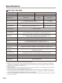
TR-71W / TR-72W------------------------------------106
Options-------------------------------------------108
7
What is TR-7W ?
Outline
Thermo Recorders TR-71W / 72W are a new type of temperature and humidity data
logger equipped with a built-in function that enables connection to and use over the
Internet or other network such as a LAN network. The downloading of recorded data,
the monitoring of current readings and the sending of warning mails can all be done
easily over the Internet or LAN network. It is possible to connect to both a wired LAN
and a wireless LAN.The use of an Internet connection provides a low cost way to
manage temperature and humidity data from long distances.
Examples of Usage
Managing Temperature and Humidity in a distant warehouse via the Internet
Managing Temperature and Humidity in a distant building or apartment house
Collecting temperature and humidity data in a factory using a wireless LAN
8
Basic Functions
TR-71W / TR-72W
Temperature Range : 60 ~ 155 °C (TR-71W)
The standard temperature sensor that comes with TR-71W has a range of 40 ~ 110°C. With the
optional sensor a wider range of 60 ~ 155°C can be measured and recorded. Please see and
purchase our optional sensors to meet your specific needs.
Humidity Measurement Range : 10 ~ 95%RH (TR-72W)
The standard sensor that comes with the TR-72W has a temperature measurement range of 0 ~
50°C and a humidity measurement range of 10 ~ 95%RH.
Recording Capacity : 8000 readings x 2 channels
Each channel can record and store up to 8000 readings. At the longest recording interval of 60
minutes, recording can continue consecutively for 1 year.
15 Recording Intervals
There are 15 recording intervals (1 second to 60 minutes) to select from. There are 2 types of
recording modes to choose from.
One Time :
Upon reaching capacity of 8,000 readings, "FULL " will appear on the LCD display and recording
will automatically stop.
Endless Loop :
Upon reaching capacity of 8,000 readings, the oldest data is overwritten and recording continues.
Changing the LCD Display
Using the software, you can choose to change the LCD display pattern from displaying either
one of the two channels or displaying both channels alternately.
Backup Function
Under normal conditions the AC adaptor should be used for measuring and recording data, but if
there is a power shortage or the AC adaptor cable beomes unusable, the backup battery can be
used for measuring and recording. Communication is not possible.
Directly Insert LAN Card for Easy Wireless Connection
By simply inserting a CF type wireless LAN card you can use a Wireless LAN connection.
* For a list of LAN cards that have been proven compatible, please see our Homepage for updates.
View Current Readings via Cell Phone Internet Browser
It is possible to view current temperature and humidity readings by simply connecting to the
Internet via your cell phone browser.
9
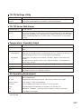
TR-7W Settings Utility
Here, settings for TR-7W can be carried out for Detailed Network Settings, Warning Report
Settings, Gather Current Readings Settings and Adjustment Settings.
Network Initialization Settings
Settings for helping to connect a TR-7W to a network.
Detailed Network Settings
Make detailed network settings here.
Warning Report Settings
If a set upper or lower limit has been exceeded, a warning report mail can be sent to up to 5
mail addresses. Also, if the TR-7W backup battery power has become low, a mail can be sent to
inform you of the fact.
Gather Current Readings Settings
Make settings to view current readings of up to 10 TR-7W loggers in the same browser.
Adjustment Function
By entering the adjustment values beforehand, it is possible to view and record the adjusted
measurement values.
About the TR-7W Series Web Viewer
With the TR-7W Series Web Viewer you can not only use a browser and manage recording
start and the downloading of recorded data, but can carry out various operations as listed
below.
Recording Settings
By setting the recording interval, the recording start time and the recording mode, recording will
begin at the set date and time.
Downloading Recorded Data
It is possible to download recorded data from the TR-7W via a browser and create files.
Monitor Current Readings
The current readings measured every 30 seconds in the TR-7W can be displayed. It is also
possible to via a cell phone browser.
Graph
Measurements taken by the TR-7W loggers can be shown in graph form which updates every 10
minutes and can show up to 1 week's worth of data.
Main Unit Settings
Clock and Calendar Settings, Button Settings, LCD Settings, Channel Name Settings, Warning
Mail Transmission Test, Forced Cancellation of Communication, Restarting the System.
10
Temp / Humidity Graph
Here, recorded data from TR-7W that has been downloaded and saved to a file can be viewed.
View and Print Temp / Humidity Graphs
View the data downloaded from the TR-7W in a list and print.
- View 8 channels of data in 1 display
Up to 8 channels of recorded data can be viewed in the same graph at one time.
- Easy zoom in and out with mouse
By selecting a range with your mouse you can easily zoom in and out on data.
- Calculate and view the highest, lowest and average readings for a desired range
In the Graph, for each channel it is possible to designate a desired range from which the highest,
lowest and average readings will be calculated and displayed.
- Graph Printing
It is possible to print in full-color the graph as you see it on display.
Data List Display / Printing
You can view the data displayed in the graph window as a list and then choose to print.
- View in Easy to Distinguish Colors
In the data list, the highest value will appear in red, the lowest in blue, and the average in pink.
- Printing the Data List
It is possible to print the entire list as displayed or to select pages for printing.
Creating Text File
It is possible to convert the data for a specified range (time period) to common text file format (CSV
type format), so that it can be exported to spreadsheet software such as Excel or Lotus.
11
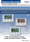
Package Contents
The following items are included in the package.
TR-71W
12
Thermo Recorder TR-71W
x 1 unit
Temperature Sensor TR-0106
x 2 Sensors
LAN Cable LN-20W
x1
AC Adaptor x 1
(AD-0605 or AD-05C1)
Software CD-ROM
x1
Introductory Guide and Warranty x 1
TR-72W
Thermo Recorder TR-72W
x 1 unit
Temperature/Humidity Sensor TR-3110 x 1
Sensor
LAN Cable LN-20W
x1
AC Adaptor x 1
(AD-0605 or AD-05C1)
Coin Type Lithium Battery
(CR-2032) x 1
Software CD-ROM
x1
Introductory Guide and Warranty x 1
13
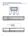
TR-71W / 72W Part Names and Functions
Logger Body
Front
DISPLAY
Button
INTERVAL
Button
REC/STOP
Button
DISPLAY Button
Pressing this button will change the LCD display mode.
INTERVAL Button
By pressing this button you can check or change the currently set
recording interval.
REC/STOP Button
By pressing this button you can start or stop recording.
* If you have deactivated the buttons in the Web Viewer [Button Operation Settings], the buttons
will not function even if pressed.
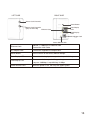
Top
CF Interface Slot
Battery Case
Insert a Wireless LAN Card. *1
CF Interface Slot
NOTE:
Do not insert anything other than a communication card.
Battery Case
Insert the backup battery.
*1 For a list of LAN cards that have been proven compatible, please see our Homepage for updates.
14
LEFT SIDE
RIGHT SIDE
Sensor Jack Channel 1
Reset Button
Sensor Jack Channel 2
(Only for TR-71W)
Data Display
LED
Ethernet Jack
LINK Display
LED
AC Adaptor Jack
Power Monitor LED
Ethernet Jack
10Base-T / 100Base-TX Ethernet Jack
Connect the LAN Cable
AC Adaptor Jack
Connect the supplied AC adaptor here.
Reset Button
Press to return to the factory default settings.
Data Display LED
When data is being input or output the lamp will blink green.
LINK display LED
The communication speed will appear in green.
Lamp on: 100Mbps, Lamp blinking: 10 Mbps
Power Monitor LED
While the power is ON, the lamp will appear green.
15
LCD Display
Channel Mark
The channel number of the measurement being displayed will appear.
Rec Mark
The recording condition will appear.
ON : Recording in progress. BLINKING :Waiting for programmed start.
Recording Capacity
After every 2000 readings the scale will be marked from left to right.
COM Mark
This will appear when data is being processed.
Recording Mode
One Time:
Upon reaching capacity of 8,000 readings, “FULL” will appear on the LCD display and recording
will automatically stop.
Endless Loop:
Upon reaching capacity of 8,000 readings,the oldest data is overwritten and recording continues.
Battery Life Warning Display
When the battery power becomes low, a mark will appear on the LCD of the main unit.
If the battery is not changed and power becomes even lower, the display will go off and all normal
operations will stop. Please change the battery as soon as the Battery Warning Mark appears.
Unit of Measurement
The channel number of the measurement being displayed will appear.
Measurements and Messages Area
Current measurements or operational messages will appear here.
16
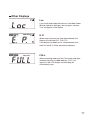
Other Displays
Loc
If you have deactivated the buttons in the Web Viewer
[Button Operation Settings], and you press a button
“Loc” will appear in the display.
E. P.
When external power has been disconnected, the
display will alternate CH1, CH2, E.P.
If the display has been set for a fixed channel, that
fixed CH and E.P. will be alternately displayed.
FULL
When recording under the One Time mode and upon
reaching capacity of 8,000 readings, “FULL” will
appear on the LCD display and recording will
automatically stop.
17
Outline of Use
Basic Operation
Getting Ready
1. Getting the TR-7W Ready to Use
Get the TR-7W logger ready to measure temperature and humidity by inserting the backup
battery, connecting the AC adaptor and the sensor(s).
2. Checking your Operating Environment
You also need to check your computer and network setup and be sure to prepare any necessary
devices like routers to enable connection to your access point.
3. Connecting to a Network
Connect the Network Cable.
See examples of connections on p.27-28 for how to connect the TR-7W to your router or
computer and upon completion turn the power ON.
* Even if you are planning to use a wireless LAN, it is necessary to make the initial settings via a wired
connection.
4. Installing the TR-7W Settings Utility
To enable set up, install the supplied software "TR-7W Settings Utility" into your computer. With
the "TR-7W Settings Utility" you will be able to make all basic network settings.
When installing the "TR-7W Settings Utility", we suggest that you also install the "Temperature
/Humidity Graph" into the same folder.
Initialization Settings
1. Network Initialization Settings.... From the TR-7W Settings Utility
To connect to a network it is necessary to enter an IP address and subnet mask that are
appropriate for your network. Under Network Settings make the appropriate settings for your "IP
address" and "Subnet mask". More detailed settings can be made in "Detailed Network Settings"
Moreover, from the TR-7W Web Viewer other settings can be made for the Main Unit and for the
TR-7W Web Viewer Display.
2. TR-7W Main Unit Clock and Calendar Settings
.... From the TR-7W Series Web Viewer
From the TR-7W Web Viewer, first set the data logger’s clock and calendar settings to your local
time. These settings will be valid until the logger’s web server is restarted or the power is turned
OFF.
18
Basic Operations
1. Recording Settings.... From the TR-7W Series Web Viewer
By setting the recording interval, the recording start time and the recording mode, recording will
begin at the set date and time.
It is also possible to set the recording interval on the logger by using the [INTERVAL] button and
to start and stop recording by using the [REC/STOP] button.
2. Gather Recorded Data.... From the TR-7W Series Web Viewer
It is possible to download recorded data from a TR-7W unit and view the data with "Temp /
Humidity Graph".
It is possible to download data while continuing to record.
3. Other Functions
Monitoring Current Readings.... From the TR-7W Series Web Viewer
In the TR-7W Web Viewer, it is also possible to view current readings via a browser. By registering
multiple loggers with the "TR-7W Settings Utility", it is possible to view current readings of up to 10 (TR7W) loggers in the same browser. The current reading will be refreshed every 30 seconds.
Warning Monitoring.... From the TR-7W Settings Utility
You can make settings to have warning mail sent when the data being recorded exceeds a set range.
Graph.... From the TR-7W Series Web Viewer
Data recorded by the TR-7W loggers can be shown in graph form which updates every 10 minutes and
can show up to 1 week's worth of data.
Adjustment Function.... From the TR-7W Settings Utility
By adjustment measurement values, it is possible to view and record the adjusted measurement values.
Temp / Humidity Graph
Graph Display.... From the Temp / Humidity Graph
Up to 8 channels (4 TR-7W units) of recorded data that has been downloaded and saved to a
file can be viewed in 1 graph.
You can view the data displayed in the graph window as a list and then choose to print.
It is also possible to convert the data to common text file format (CSV type format).
* We advise that you save displayed and edited data as is necessary.
19
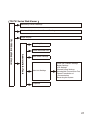
Operational Settings
TR-7W Settings Utility
Detailed Network Settings
TR-7W Settings Utility
Warning Report Settings
IP address, Subnet Mask, Port Number
Login ID, Password
DNS, SNTP
SMTP Mail Server
IP Block
Wireless LAN
POP Before SMTP Settings
SMTP Authentication Settings
Rebooting the TR7W (Restarting the System)
Warning Report Settings
Warning Report Mail Recipient Address
Settings
Adjustment Settings
Adjustment Settings, Initialization
Gather Current Readings Settings
View Multiple Current Readings Settings
20
TR-7W Series Web Viewer
Monitoring Current Readings
Monitor a Multiple Number of Current Readings
Graph Display
Gather Recorded Data
Administrator Tools
TR-7W Series Web Viewer
Recording Start
WEB Viewer Settings
Main Unit Settings
Clock and Calendar Settings
Button Settings
LCD Settings
Channel Name Settings
Warning Mail Transmission Test
Forced Cancellation of
Communication
Restarting the System
Properties
21
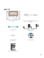
Getting the TR-71W / 72W Ready to Use
Installing the Backup Battery
1. Pull out the battery case.
2. Insert the battery into the case making sure not to mistake +/-.
Insert a new battery into the case.
3. Replace the battery case.
There are no POWER switches on the TR-71W/72W units. Once the battery is
reinserted, power will go on.
22
Battery Functions
Under normal conditions the AC adaptor should be used for measuring and recording data, but
if there is a power shortage or the AC adaptor cable becomes unusable, the backup battery
can be used for measuring and recording.
NOTE:
- Communication cannot occur with only the backup battery.
- If no battery has been installed and the AC adaptor power cannot be used, all data will be lost. So,
please be very careful.
Replacing the Battery
When the battery power becomes low, a mark will appear on the LCD of the main unit. If the
battery is not changed and all power is lost, the saved data will also be lost. Please change the
battery as soon as the Battery Warning Mark appears.
NOTE:
- Battery performance deteriorates by natural discharge and corrosion. We suggest changing batteries
somewhere between one and two years use.
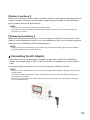
Connecting the AC Adaptor
Please make sure to use the proper AC adaptor for your local voltage. The AD-0605 AC
adaptor has an input range of 100 to 120V, the AD-05C1 AC adaptor has a range of 100 to
240V.
To ensure a proper connection make sure that the plug is completely inserted.
NOTE:
- Do not use an AC adaptor other than the one that is supplied with the product. Doing so may cause fire
or other trouble.
- Insert the AC adaptor plug into the socket. Inserting the plug into a socket with different voltage may
cause fire or other trouble.
- Do not insert or pull out the AC adaptor plug with wet hands or if there are water drops on the plug; it
may cause electrocution.
23
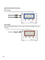
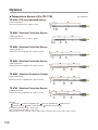
Connecting the Sensors
TR-71W
To ensure a proper connection make sure that the plug is completely inserted.
TR-72W
When using the temperature/humidity sensor in environments where the temperature is 0 to 15
and humidity under 30 RH, there may occur changes in measurement readings. This is not a
malfunction.
- To ensure a proper connection make sure that the plug is completely inserted.
24
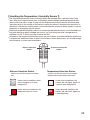
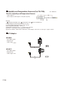
Handling the Temperature / Humidity Sensor
The temperature/humidity sensor should probably be changed after a period of about one
year. After removing the sensor from its package, please change the temperature/humidity
sensor after one year’s usage. During use the temperature/humidity sensor will accumulate
impurities (dirt) on the surface of the sensor causing the sensor's accuracy and sensitivity to
decrease. If the sensor is being used in a bad environment (smoky or dusty places) it may be
necessary to change the sensor sooner.
When the temperature/humidity sensor is not being used, please place it in the attached vinyl
bag with the drying agent included and store it in a cool dark place with a temperature of
between 5 to 25 °C and a humidity of below 30%RH.
Attached to the temperature/humidity sensor are two stickers: a wetness detection sticker and
a temperature detection sticker. If either of the stickers shows abnormality, you should change
the old sensor to a new one immediately.
Wetness Detection
Sticker
Wetness Detection Sticker
Informs you that the sensor has been
wet.
Normal
Under normal conditions, black
dots will appear on a white
background.
Under abnormal conditions, the
background will turn to red.
Abnormal
Temperature Detection
Sticker
Temperature Detection Sticker
Informs you that the sensor measured a
temperature measurement over 60°C.
60
Normal
60
Abnormal
Under normal conditions, the
number "60" will lightly appear on
a pinkish white background.
Under abnormal conditions, the
number "60" will clearly appear on
a red background.
25
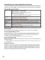
Checking your Operating Environment
To properly use the logger, the following operational environment is necessary.
PC Operating Environment
OS
Microsoft Windows 7 32/64bit English
Microsoft Windows Vista 32bit English
Microsoft Windows XP 32bit(SP2 or above) English
Microsoft Windows 2000 English
* To install the TR-7W Settings Utility, it may be necessary to have Administrator
Rights for the computer into which it will be installed.
PC/CPU
A Stable Windows Operating Environment
LAN, TCP/IP Communication Possible
Memory Capacity
Enough memory to stably operate Windows
Disc Space
More than 10MB of free space (More free space is necessary for data)
Monitor
VGA (SVGA higher than 800 x 600 recommended), more than 256 colors
LAN
100BASE-TX or 10BASE-T
Twisted pair cable confirming to Category 5 (STP / UTP)
Web Browser
Internet Explorer 6.0 or higher
Using a LAN
Connect the provided LAN cable to the HUB that is connected to your computer.
Connecting Directly to a PC
Connect the TR-71W / 72W to your computer with the supplied LAN cable or a LAN
cross cable. If communication is not possible with the supplied LAN cable; please
purchase a cross LAN cable separately.
- LAN cross cables are not included with the product. Please purchase separately.
Using a Wireless LAN
Please use a Wireless LAN card and a Wireless LAN access point (Combined Wireless
LAN and Hub OK).
- For a list of LAN cards that have been proven compatible, please see our Homepage for updates. ( http://
www.tandd.com)
Using the Internet
In order to connect to the Internet, you must first make arrangements with a provider
for a line. It may also be necessary to get an IP address or domain and make domain
name server and other settings. For more details about various settings, it is best, if
present, to contact your network administrator. To get more details about your Internet
connection and setup, please contact your provider.
26
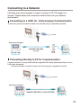
Connecting to a Network
Following are some examples of ways to connect a TR-7W logger to a
network. Please select the connection method that suits your network
environment.
Connecting to a HUB for Intracompany Communication
To ensure a proper connection make sure that the plug is completely inserted.
To HUB
Connection Examples
Connecting Directly to PC for Communication
If communication is not possible with the supplied LAN cable; please purchase a cross
LAN cable separately.
To ensure a proper connection make sure that the plug is completely inserted.
To Computer
Connection Examples
27
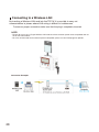
Connecting to a Wireless LAN
By inserting a Wireless LAN card into the TR-7W, it is possible to carry out
communication in places where LAN wiring is difficult or troublesome.
To ensure a proper connection make sure that the plug is completely inserted.
NOTE:
- Please do not use any CF type Wireless LAN cards that have not been proven to be compatible and are
not on our LAN card list .
- For a list of LAN cards that have been proven compatible, please see our Homepage for updates.
Connection Examples
28
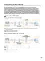
Connecting to the Internet
In order to connect the TR-7W to the Internet you must first set up an Internet
connection environment by making arrangements with a provider for a line and get
a global IP address and domain. Also, if necessary, make all domain name server
and / or router settings. For more details about various settings, it is best, if present,
to contact your network administrator. To get more details about a global IP address
and domain, please contact your provider. The following are examples of connection
methods. Please select the connection method that suits your network environment.
Connection Examples
Using the TR-7W on the Internet
In your computer browser, open the global address that has been assigned to the TR-7W. (ex: 218.227.168.66)
Call up via the provider or router.
Data is returned from the TR-7W.
Using a Domain Name (ex : tr-7w.net)
From your computer browser, open the domain name. (ex : tr-7w.net)
The domain name will be converted to a global IP address by the DNS server and the TR-7W will
be called.
Data is returned from the TR-7W.
29
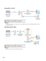
Using Mail via LAN
The TR-7W accesses the SMTP server and sends mail.
The SMTP server delivers the received mail.
The computer receives mail from the POP mail server.
NOTE :
- In order to receive mail, it is necessary to have a SMTP mail server and a POP or IMAP mail server
located on the LAN.
Sending Internet Mail
The TR-7W accesses the SMTP server and sends mail.
The SMTP server delivers the received mail.
The computer receives mail from the POP mail server.
NOTE :
- Please make all necessary router (LAN) settings.
30
Installation
Install the provided software.
Is Windows® operating properly?
®
If Windows is not operating properly, "TR-7W Settings Utility" and "Temp /Humidity Graph"
may not be installed correctly or it may not operate properly.
Please quit all other applications.
If other programs are open, please close and quit all of them, making sure to quit all Quick
Start programs such as a virus checker.
* To install the [TR-7W Settings Utility], it may be necessary to have Administrator Rights for the computer
into which it will be installed.
* This software is compatible with Windows Vista and Windows 7. The layout of the installation window
for Windows Vista / 7 closely resembles that of Windows XP (SP2). Please refer to the installation
instructions for Windows XP (SP2) below, and follow the on-screen messages as they appear when
installing the software into Windows Vista / 7.
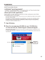
1. Open Windows .
®
2. Place the accompanying CD-ROM into your CD-ROM drive.
In a few seconds, the "Install Program" window will appear.
- If that window does not automatically open, please open it by double clicking the CD-ROM icon in "My
Computer" on your desktop.
Or, if after double clicking the CR-ROM drive, the file appears in the CD-ROM folder, double click on the
"start.exe" icon.
Click here
[Execute]
button
31
3. Select "Install TR-7W Settings Utility" and click the [Execute]
button to start the installation.
4. Continue the installation by following the directions as they
appear. During installation, you can choose which modules you
wish to install. Please select the modules you wish and follow
the installation directions.
Click here
[Next]
button
5. After installation has been completed, "TR-7W for Windows" will
be registered in the Window's "Start" Menu.
32
Operating the TR-7W Settings Utility
How to Open
From the list of programs in the Window’s Start Menu, click on "TR-7W for Windows""TR-7W Settings Utility.
Using Help
For details about how to use the software, please see the explanations in the Software
Help Menu.
- By clicking on "Help" in the Menu Bar and then "How to Use TR-7W Settings Utility" you can click on one
of the tabs "Contents" or "Index" to search for the topic or term you are unsure about or have questions
about.
Contents
By clicking on one of the topics listed, you can find detailed information for that subject.
Index
By selecting a keyword in the Index list, and clicking the [View] button at the bottom, a detailed
explanation will appear.
By clicking the [Help] button in a dialog box, an explanation for that dialog box will appear.
33
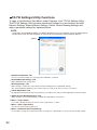
TR-7W Settings Utility Functions
To open, in the Windows Start Menu, under Programs, click "TR-7W Settings Utility".
The TR-7W Settings Utility contains operational settings for such functions as Initial
Network Settings, Warning Report Settings, Gather Current Reading Settings and
others operational settings as explained below.
NOTE:
- If you open "TR-7W Settings Utility" on multiple computers in the same network, it may not work properly.
Please open it from only one computer at a time in the same network (same broadcast domain).
[Menu]
"Network Initialization" Tab
Here you can make settings for connecting a TR-71W/72W to a network.
"Detailed Network Settings" Tab
Make detailed Network settings here.
"Warning Settings" Tab
Make settings to send mail to report when measured readings have exceeded limit settings.
Also, if the TR7W backup battery power has become low, a mail can be sent to inform you of the fact.
"TR-7W Adjustment" Tab
By adjustment measurement values beforehand, it is possible to view and record the adjusted measurement values.
"Gather Current Reading Settings" Tab
Make settings to view current readings of multiple TR-71W/72W's in one browser.
"Menu"-"Login History"
If you wish to disable the History Function, select "Login History" -> "OFF".
"Menu"-"Clear Login History"
Use this to erase the entire login history.
"Menu"-"Communication Time Settings"
It is possible to change the communication time for all types of communication to match your network environment.
34
Network Initialization Settings
To connect a TR-7W to a network, it is necessary to make the correct IP Address and
Subnet Mask settings appropriate to your network environment.
NOTE :
- To make IP address changes, connect one TR-7W unit at a time and carry out the changes. Please note
that upon purchase, all TR-7W units are set with the same IP address. Do not connect more than one
unit with the same address to the network at the same time.
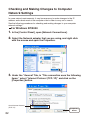
1. It is necessary to connect to the same network as to which the
computer you have opened this application (TR-7W Settings
Utility) is connected to.
2. In "TR-7W Settings Utility", click on the "Network Initialization"
Tab and then click on the [Search] button. After clicking, the
search results will be shown in about 5 seconds.
The factory default settings for TR-7W are as follows: IP Address : "192.168.1.200",
Subnet Mask : "255.255.0.0".
The MAC address is written on a sticker on the back of the TR-7W logger.
Connected
TR-7W Loggers
[Search]
button
[Change Settings]
button
35
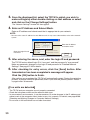
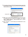
3. From the displayed list, select the TR7-W to which you wish to
make settings by either double clicking on that address or select
and click on the [Change Settings] button.
The "Network Settings" window will then appear.
4. Enter an IP Address and Subnet Mask.
Enter an IP address and subnet mask that is appropriate for your network.
NOTE :
- Do not use the same IP address for two different units. It may cause abnormalities to the entire network
system.
Enter the IP address
and subnet mask
Enter the Login ID and
Password
[Send]
button
5. After entering the above, next, enter the login ID and password.
The TR-7W factory default login ID is "wsc-user" and the password is "wsc-passwd".
Make any necessary changes to the login ID and password at "Detailed Network
Settings". See page 37-39 for details.
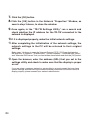
6. After checking for entry errors, click the [Send] button. After
transmission has been completed a message will appear.
Click the [OK] button to finish.
After settings are completed the TR-7W will automatically restart. During the restarting
process, a search cannot be performed, even if you click the [Search] button. Please
try again after 30 seconds.
If no units are detected
-The TR-7W and your computer are not properly connected.
-Check the hub power switch and the network cable type.
-In some network environments, it may be necessary to make changes to the IP address and
subnet mask at the computer side in order to carry out a search. For details, see page 82-88
[Checking and Making Changes to Computer Network Settings].
-Do not use a LAN card which has not been formatted.
36
Detailed Network Settings
Make more detailed network settings for the TR-7W here.
* Before making any settings here, please set the TR-7W with the proper IP address.
Sending the Settings
1. Click the [Detailed Network Settings] Tab.
2. In the [Get Settings] Area, enter the information for the TR-7W you
wish to make settings for and click the [Get Settings] button. The
current settings will appear.
A list that shows all of the IP addresses and domain names with which successful
communication has occurred until now will appear in the [Settings History].
If you select an IP address or domain name here, the Login ID, Password and Port
Number will be entered automatically.
- Note that if you have turned [OFF] the [Login History] in the [Menu] or if you have deleted the Login
history by having clicked [Clear Login History] the Settings History will not appear.
"Settings History"
Enter info of the TR-7W you
wish to make settings for
[Change Settings]
button
[Get Settings]
button
37
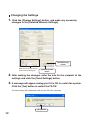
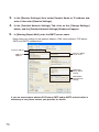
Changing the Settings
1. Click the [Change Settings] button, and make any necessary
changes to the [Detailed Network Settings].
[Send Settings]
button
Enter info of the TR-7W you
wish to make settings for
[Restart TR-7W]
button
2. After making the changes, enter the info for the recipient of the
settings and click the [Send Settings] button.
3. A message will appear asking you if it is OK to restart the system.
Click the [Yes] button to restart the TR-7W.
The new settings will not become valid until the TR-7W is restarted.
[Yes] button
38
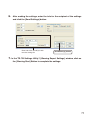
4. After the reactivation has been completed, the settings will have
been successfully made.
[Restart TR-7W] Button
If the browser does not open, if there is an error in the clock settings when getting current
readings from a number of loggers, or if any errors occur during communication, click the [Restart
TR-7W] button.
Note that by restarting, the graph in the TR-7W Web Viewer will also be reset.
NOTE:
- that by clicking the [Send Settings] button or the [Restart TR-7W] button over and over, communication
may become impossible.Please try again after 20 seconds.
39
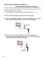
Returning the Network Settings to the Factory Default Settings
If you have forgotten the IP address or the password you can easily return the
logger to the default factory settings.
* With the backup battery, the recorded data in the TR-7W will be saved as is.
* The "warning settings" and "get current reading settings" will also be saved as they are.
1. Pull out the AC adaptor plug from the TR-7W logger.
2. Press in the [RESET] button on the TR-7W logger with a sharp
object and while pressing in, reconnect the AC adaptor.
3. When the [Power Monitor LED] on the TR-7W logger starts
blinking, release the [RESET] button and the unit will have been
returned to the factory default settings.
40
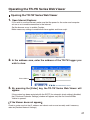
Operating the TR-7W Series Web Viewer
Opening the TR-7W Series Web Viewer
1. Open Internet Explorer.
If you wish to use the Internet, make sure that the power for the router and computer
are on so as to enable connection to the Internet.
Set the browser so as to enable Cookies.
Make necessary settings to enable both Java applets and Java script.
2. In the address area, enter the address of the TR-7W logger you
wish to view.
Enter address
3. By pressing the [Enter] key, the TR-7W Series Web Viewer will
appear.
If the system has been restarted with the SNTP (for automatic clock settings) disabled,
the [Clock and Calendar Settings] window will appear only the first time the Web
Viewer is opened.
If the Viewer does not appear
Check to make sure that the IP address and subnet mask are set correctly and if necessary
redo the [Detailed Network Settings].
41
TR-7W Series Web Viewer Functions
Upon opening the TR-7W Series Web Viewer, communication will begin with the TR7W logger and the current readings monitor will appear.
With the TR-7W Series Web Viewer you can not only use the browser and manage
recording settings and the downloading of recorded data, but can also carry out various
operations as listed below.
Monitor Current Reading Window
Initial Clock and Calendar Settings Window
Monitor Current Readings
The current readings measured every 30 seconds in the TR-7W can be displayed and viewed.
Monitor Multiple Current Readings
By registering a multiple number of TR-7W loggers in [TR-7W Settings Utility], it is possible to
simultaneously view a number of current readings from multiple loggers.
Graph
Measurements taken by the TR-71W loggers can be shown in graph form which updates every
10 minutes and can show up to 1 week's worth of data.
Administrator Tools
To open Administrator Tools, the Login ID and Password are needed.
Recording Settings ---------Make setting changes to the recording conditions.
Download Recorded Data-Download recorded data to a computer and create files.
WEB Viewer Settings ------Make changes to names of the Main Title, Window Title and Footer.
Main Unit Settings -------- Make various settings concerning the TR-71W loggers.
Properties--------------------- Displays all of the TR-7W settings.
42
Clock and Calendar Settings
If the TR-71W's date and time are set incorrectly, the recording start time, the
download data time, and the monitor current readings time will all be wrong.
Please make sure to set correctly before beginning to use.
NOTE :
- If you make clock settings manually, the clock will lose its settings upon removal of the AC adaptor or
after restarting the system. Hence, it is necessary to reset the clock after having restarted the system
or having lost AC power. By using the Auto-clock Settings (SNTP Settings) it is possible to have the
clock automatically reset to the current time upon restarting the system. For more details about making
settings for the Auto-clock settings see page 62-63.
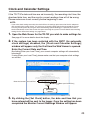
1. Open the Web Viewer for the TR-7W you wish to make settings for.
See page 41 for more details about the display.
2. If the system has been restarted with the SNTP (for automatic
clock settings) disabled, the [Clock and Calendar Settings]
window will appear only the first time the Web Viewer is opened.
Enter the Current Date and Time.
By clicking [Enter your Local Time], your current computer settings will automatically
be entered.
If using [Enter your Local Time], please make sure that your computer clock settings
are correct.
Enter the Current Date and Time
[Enter your Local Time]
[Set Clock]
button
3. By clicking the [Set Clock] button, the date and time that you
have entered will be sent to the logger. Once the setting has been
completed the Monitor Current Readings Window will appear.
43
Recording Settings
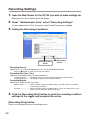
1. Open the Web Viewer for the TR-7W you wish to make settings for.
See page 41 for more details about the display.
2. Under "Administrator Tools" select "Recording Settings".
To open Administrator Tools, the proper Login ID and Password are needed.
3. Setting the Recording Conditions.
[Recording Start]
button
[Recording Stop]
button
Recording Interval
Select from : 1,2,5,10,15,20,30 seconds, or 1,2,5,10,15,20,30,60 minutes
Click the [
] button to select an interval from the list.
Recording Start Date / Time
Select from : Immediate Start / Programmed Start>
Immediate Start-------- Recording will start after the [Recording Start] has been clicked.
Programmed Start ---- Recording will begin on the set date and time.
Recording Method
Select from : Endless Loop / One Time
Endless Loop------------ Upon reaching capacity of 8,000 readings, the oldest data is overwritten
and recording continues.
One Time------------------ Upon reaching capacity of 8,000 readings, "FULL"will appear on the LCD
display and recording will automatically stop.
4. Click the [Recording Start] button to send the recording condition
settings to the logger and complete the set-up.
[Recording Stop] button
Press to stop recording during a recording session.
44
Gathering Recorded Data
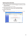
1. Open the Web Viewer for the TR-7W logger from which you wish
to download data.
See page 41 for more details about the display.
2. Under"Administrator Tools" select "Recording Settings".
To open Administrator Tools, the proper Login ID and Password are needed.
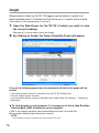
3. Click the [OK] button.
NOTE:
- While downloading recorded data, DO NOT use the back button on the browser to view previous pages
AND DO NOT use the refresh button to reload a page.
[OK]
button
45
4. Click the [Download] button.
[Download]
button
5. In the "File Download" Window, click the [Save] button, assign a
name to the file and save to complete the process.
NOTE:
- By clicking the [Open] button, the "Temp / Humidity Graph" may not function properly. Please do not click
the [Open] button.
6. After the downloaded data has been saved by clicking the [Open
File] button, the [Temp / Humidity Graph] will appear.
Clicking the [Open Folder] button will open the folder in which the data was saved.
Clicking the [Close] button will finish the process.
46
Operating the Temp / Humidity Graph
How to Open
From the list of programs in the Window’s Start Menu, click on "TR-7W for Windows""Temp / Humidity Graph".
Using Help
For details about how to use the software, please see the explanations in the Software
Help Menu.
- In the Menu Bar, click "Help"-"Search by Topic", then click on one of the tabs "Contents", "Index", or
"Search Text" to search for the topic or term you are unsure about or have questions about.
Contents :
By clicking on one of the marks next to the topics listed, you can find detailed information for that
subject.
Index :
To get an explanation from a keyword, select a keyword from the Index list, and then click the
[View] button.
Search :
Enter the keyword you wish to search for and click the [Start Search] button. All topics that
contain the keyword will be displayed. By selecting a topic and clicking the [View] button at the
bottom, a detailed explanation will appear.
-By clicking the help button in a dialog box, an explanation for that dialog box will appear.
-In the Graph window, by clicking on the " " in the Toolbar, simple explanations will appear the
next time you click on a menu, an icon, or objects in the main window.
47
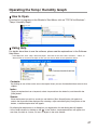
Temperature / Humidity Graph Display Names and Functions
A and B Cursor Movement Buttons
By clicking the arrow buttons, you can simultaneously move the A/B cursors.
A and B Cursor Buttons
Click and drag the A or B button to move the cursor to the left or right.
Toolbar
Buttons appear for frequently used commands.
Menu Bar
Click on the desired menu in the Menu Bar to set or display each function from which you can choose from an array of
commands.
Button for Moving Horizontal Axis
The time axis moves by clicking these arrow buttons.
Horizontal Gauge Bar
By dragging the gauge you can move left and right to the data you want to be displayed.
Button for Moving Vertical Axis
The vertical axis moves up or down by clicking these arrow buttons.
Vertical Gauge Bar
By dragging the gauge you can move up and down to the data you want to be displayed.
A and B Cursor Position Information
The approximate date and time for the A and B cursor positions and the time difference between the A cursor and the
B cursor is displayed.
Channel Info List Display
The detailed data info for each channel 1 to 8 is displayed below the Graph Display.
48
Zoom in Using the Mouse
With the left button drag the mouse to outline the area you want to zoom in on.
Menu Display Using the Mouse
By right clicking on the graph, the Menu will be displayed.
49
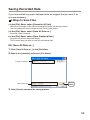
Data List Display Part Names and Functions
This is a list of the data that was displayed in graph form. ("View" Menu)
[Date / Time] Button:
By clicking this button, you can shift the display between the recorded date and the amount of
elapsed time since recording started.
[Date/Time]
button
Recorded Date
Display
The highest value is in RED, lowest is in BLUE, and the average is in PINK.
Scroll Bar: By dragging it up and down you can move to the data you want.
Elapsed Time
Display
Menu Display Using the Mouse
By right clicking on the graph, the Menu will be displayed.
50
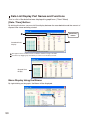
Making Changes to the Graph Display
Changing Colors of Data Display Area : [View] Menu
You can change the letters used in the data list display for each channel between
monochrome and channel color.
Viewing and Hiding Channels in Graph : [View] Menu
You can choose to view only the selected channels in the Graph.
1. By moving the mouse to [Selected Channels ON / OFF], the channel numbers are
displayed.
2. Click the channel number to remove or place a check mark. Only those channels with a
check mark next to the number will be displayed in the Graph.
The same operation can be done by clicking on the channel number icons in the
Toolbar.
Check mark
Enlarged
51
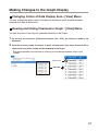
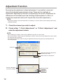
Setting the Max. Min. Avg Calculation Range : [Tools] Menu
1. Set the calculation range in the [Set High, Low, Avg. Calculation].
[OK]
button
Enter the numerical
values
[Entire Graph]
button
-By clicking the [Entire Graph] button, the dates and times for the entire graph will be
displayed.
-If in the graph display, place the A cursor at the position for the beginning of the calculation
range and the B cursor at the end of the range, and those dates and times will appear as the
new range in the [Set High, Low, Average Calculation Range] Display when it is opened.
2. Click the [OK] button to finish.
52
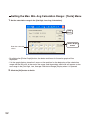
Editing Recording Conditions : [Tools] Menu
It is possible to make corrections to channel names and to recording start date and
times.
1. By clicking the [Channel. No.] button of the channel you wish to edit, the "Name" and
"Started Date / Time" in the "Edit Items" display will show info for that channel number.
Name: Up to 32 letters can be entered.
Starting Date/Time : The month, day, year, hour, minute and second can be changed.
[OK]
button
Channel Number
[Restore]
button
Edit Items
2. Click the [OK] button to finish.
If you wish to continue to change other channels, repeat the process as in 1.
The [Restore] button is only effective while making changes. After clicking the [OK]
button the settings cannot be restored to the original settings.
53
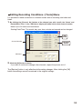
Reordering Channel Data: [Tools] Menu
You can re-order the data during graph display.
There are two methods to use when re-ordering channels : [Re-order by Dragging a
Channel Number] and [Specify the Channel Numbers to be Moved].
Re-order by Dragging a Channel Number
Drag the channel number you wish to move to the newly desired channel number position and
drop it.
- The [Restore] button is only effective while making changes. After clicking the [OK] button the settings
cannot be restored to the original settings.
[OK]
button
Drag the channel number you wish
to move to the desired position.
[Restore]
button
Specify the Channel Numbers to be Moved
1. Specify the channels to be moved From : (original position) To : (desired position).
2. Click [Re-order] button to complete the re-ordering process.
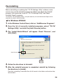
The [Restore] button is only effective while making changes. After clicking the [OK]
button the settings cannot be restored to the original settings.
[OK]
button
[Restore]
button
If you wish to move Ch.3 to Ch.7
simply set From: Ch.3, To: Ch.7
54
[Re-order]
button
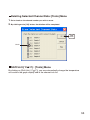
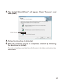
Deleting Selected Channel Data: [Tools] Menu
1. Put a check on the channel number you wish to erase.
2. By clicking on the [OK] button, the deletion will be completed.
[OK]
button
Check
Shift Unit (°C °F) : [Tools] Menu
By clicking on [Shift Unit (°C °F)], you can automatically change the temperature
unit scale in the graph display and in the channel info list.
55
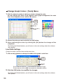
Change Graph Colors : [Tools] Menu
1. Click the channel number of which you wish to change the color.
You can change the colors of the channel name, graph background, the scale
lines, the enlarged box area, and the AB cursors.
[OK]
button
[Default]
button
[Line Width...]
button
Color Sample
2. Choose the color you want and click the [OK] button.
3. After confirming the color, by clicking the [OK] button
the change will be
completed.
By clicking the [Default] button, you will return to the color settings when the software
was opened.
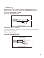
Line Width Settings
Change the width of the data lines and the scale lines.
1. Click on the [
] button to change the width of the graph / scale lines.
[OK]
button
[Default]
button
Every time you click on
Every time you click on
, the numerical value gets larger.
, the numerical value gets smaller.
2. Click the [OK] button to complete the changes.
By clicking the [Default] button, you will return to the color settings when the software
was opened.
56
Copy Display to Clipboard : [Tools] Menu
By clicking [Copy Display to Clipboard], you can copy the currently displayed window to
the clipboard and make use of the graph by pasting to other software.
57
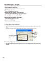
Operating the Graph
Returning to Original Size
Clicking here will return the graph to its original size.
Zooming In and Out
Zooms in or out one step at a time.
Moving the A/B Cursors Right and Left
Simultaneously move the AB Cursors to the right or left.
Moving Right and Left on the Graph
Move the Graph Display to the right or left.
Moving Up and Down on the Graph
Move the Graph Display up or down.
Vertical Axis Settings
Set the vertical axis scale (temperature).
1. Check either [Auto] or [Manual].
AUTO: The vertical axis will automatically be changed according to the values of the
data.
MANUAL: You can set the upper and lower values of the vertical axis scale.
[OK]
button
If using Manual:
Enter the range of
the vertical axis
scale.
[Default]
button
2. Click the [OK] button to finish.
By clicking the [Default] button, you will return to the settings when the software was
opened.
58
Saving Recorded Data
If you have edited any graph displayed data we suggest that you save it as
you see necessary.
3 Ways to Save Files.
In the [File] Menu, select [Overwrite All Data]
Will save any changes to file without changing File Name and Saving Location.
The same operation can be carried out from [Save] in the Toolbar.
In the [File] Menu, select [Save All Data as...]
Save with a new File Name.
In the [File] Menu, select [Save Displayed Data]
Save only that data in the current display.
This is handy when you wish to save only the desired data.
EX: [Save All Data as...]
1. Click [Save All Data as...] in the [File] Menu.
2. Specify the [Location] and enter a [File Name].
Assign a Location
Enter File name
[Save]
button
3. Click [Save] to complete the saving process.
59
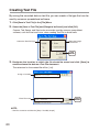
Creating Text File
By saving the recorded data as text file, you can create a file type that can be
read by common spreadsheet software.
1. Click [Save in Text File] in the [File] Menu.
2. Select the [Save in Text File] and [Range to be Saved], and click [OK].
Comma, Tab, Space, and Semi-colon are codes used by common spreadsheet
software, such as Excel and Lotus, when reading Text File to divide cells.
Select the Text File Type
Select the Range
to be Saved
[OK]
button
3. Designate
the location to which the file should be saved and click [Save] to
create and save the data as a Text File document.
The extension for the created file will be [ .txt].
Assign a Location
Enter File name
NOTE :
- Text File cannot be read into the [Temp / Humidity Graph].
60
[Save]
button
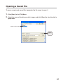
Opening a Saved File
To open a previously saved file, designate the file name to open it.
1. Click [Open] in the [File] Menu.
2. Select the name of the data you wish to open and click [Open] to view the data in
graph form.
Select a file to open
[Open]
button
61
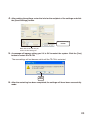
Auto-clock Settings (SNTP Settings)
If you make the TR-7W clock settings manually, the clock will lose its settings
upon removal of the AC adaptor or after restarting the system. However, by
making settings to enable the SNTP server it is possible to have the clock
automatically reset to the current time upon restarting the system.
If the TR-7W’s date and time are set incorrectly, the programmed recording
start time, the download data time, and the monitor current readings time will
all be wrong. We therefore strongly suggest that you make settings to use the
SNTP server.
-The SNTP (NTP) server is a server that automatically adjusts the clock settings of a terminal
on a network.
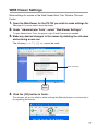
1. Open
the [TR-7W Settings Utility], click on the [Detailed Network Settings] tab,
and gather the settings for the TR-7W logger that you wish to make settings for.
2. Click
the [Change Settings] button and the Detailed Network Settings window
will appear, where you can make changes to the settings.
3. Under [SNTP Settings], click “ON” to change the setting.
How to find an NTP server
-If you are connected to an intra company LAN, you may already have an NTP server for your
network. Please ask your network administrator for details.
-If you are connected to the Internet, some providers will have an NTP server open to the
public. Please ask your provider for details.
-If you wish to use an NTP server that is open to the general public on the Internet, it is
possible to make a search for [NTP server] using Yahoo or Google. Many universities or
scientific facilities will have the NTP server open to the public.Make sure to use a server
which is the closet to your location.
Please also make sure to check whether connection is free and without limitation.
It should also be noted that depending on your Internet connection and your firewall settings,
the NTP packet may be prohibited from being accepted into your system.
62
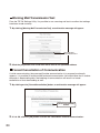
4. After making the settings, enter the info for the recipient of the settings and click
the [Send Settings] button.
[Send Settings]
button
Enter info of the TR-7W you
wish to make settings for
5. A message will appear asking you if it is OK to restart the system. Click the [Yes]
button to restart the TR-7W.
The new settings will not become valid until the TR-7W is restarted.
[Yes]
button
6. After the restarting has been completed, the settings will have been successfully
made.
63
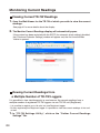
Monitoring Current Readings
Viewing Current TR-7W Readings
1. Open the Web Viewer for the TR-7W of which you wish to view the current
readings.
See page 41 for more details about the display.
2. The Monitor Current Readings display will automatically open.
If the system has been restarted with the SNTP (for automatic clock settings) disabled,
the [Clock and Calendar Settings] window will appear only the first time the Web
Viewer is opened.
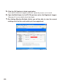
Viewing Current Readings from a Multiple Number of TR-7W Loggers
It is possible to view simultaneously in one browser, the current readings from a
multiple number of registered TR-7W loggers via one TR-7W unit (Registrant).
-It is possible to register up to 10 units into one Registrant logger.
-By also registering the Registrant logger it is possible to view the current readings of that unit
as well.
1. In
"TR-7W Settings Utility", click on the "Gather Current Readings
Settings" Tab.
64
2. Enter the Registrant Info.
A list that shows all of the IP addresses and domain names with which successful
communication has occurred until now can be viewed in the [History] pull down menu.
You can select an IP address from the [History] pull down menu.
- Note that if you have turned [OFF] the [Login History] in the [Menu], or if you have deleted the Login
history by having clicked [Clear Login History] the Settings History will not appear.
Enter info for the TR-7W you wish
to make the Registrant Logger
[Receive Registrant Info]
button
Enter info for the TR-7W unit(s)
you wish to make Remote Units.
[Remote Unit Registration] button
3. By clicking on the [Receive Registrant Info] button, you can easily confirm
the registration info.
All registration info will be displayed in the [Registration Info List].
4. Register the TR-7W unit(s) as Remote Units.
Registration Name
Will appear when viewing the current readings.
-You cannot use these symbols: <, >, ", ' .
URL
As the URL enter the IP address or Domain Name for the TR-7W unit you wish to register.
65
5. Click the [OK] button to finish registration.
If you wish to continue to register more units, repeat the process as in 4 and 5.
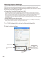
6. Open the Web Viewer for the TR-7W you have set as the Registrant Logger.
See page 41 for more details about the display.
7. By
clicking [Monitor Multiple Units], you will be able to view the current
readings for all of the units which you have registered.
66
"TR-7W Settings Utility"-"Gather Current Readings Settings"Tab
Window
[Receive Registrant Info]
button
[Send List Info] button
[Delete] button
[Delete All] button
[Receive Registrant Info] Button
The remote TR-7W registration info that had been entered into the Registrant Info will be
displayed.
[Send List Info] Button
By clicking on the [Send List Info] button, the registration info in the list will be sent to the
Registrant TR-7W. This is particularly helpful when you wish to send the same registration info to a
different Registrant Logger.
[Delete] Button
Pressing this will delete the selected remote unit from the [Registration Info List].
[Delete All] Button
Pressing this will delete all registration info from the TR-7W which is the recipient of the
communication. If registration info for any remote units is displayed in the list, all of that
info will be erased. If a communication error occurs at this time, the registration info will
not be erased from the recipient of the communication.The best way check as to whether
the deletion was successful or not, is to receive the Registrant Info.
67
Warning Report Settings
With this you can send warning report mails to a registered Internet mail
address. Also, in the Monitor Current Readings Window, the channel for which
the warning occurred will appear RED.
Temperature / Humidity Warning Report Mail
The TR-7W checks the current reading every minute and sends a warning report mail if the
upper or lower limit has been exceeded. Because of this, a second warning report mail will not
be sent until the warning settings have been changed, the reporting has been stopped, or the
measured value falls back within the acceptable range and once again exceeds a limit.
If no Upper or Lower limit settings have been made, only the Backup Battery Power Warning Mail
will be functioning.
Backup Battery Power Warning Mail
The TR-7W will check the voltage of the backup battery once a day at 12:00 pm. If the backup
battery power is below standard, a warning mail will be sent.
1. In "TR-7W Settings Utility", click on the [Warning Settings] Tab.
2. Make the desired settings.
Settings History
[Warning Start]
button
Enter the Recipient
Info.
[Warning Stop] button
[Get Settings]
button
68
Type of Unit
Select the type of device.
Monitoring Status
"Monitoring Warnings" or "Warnings Stopped" will appear.
Upper and Lower Limit Settings
The setting ranges are as follows: Temperature: Celsius -60 to 155 / Fahrenheit -76 to 311.1 and
Humidity: 0%~100%
You can also select whether to measure and record in Celsius or Fahrenheit.
Recipient Address
A warning report mail can be sent to up to 5 mail addresses.
The address cannot exceed 128 characters.
- You cannot use a space.
Sender Address
This will only used in the mail display to show where a warning report mail has been sent from.
It should be noted that if you assign an imaginary address, in some cases the SMTP server will
judge the mail to be SPAM or junk mail and not allow it to be sent. If you do use an imaginary
address, make sure the address is permissible on your SMTP server
Subject
Set the Subject Title for the Warning Mail.
Even if you make no settings here, the title "Warning Report Mail" will be automatically set.
The title can use up to 32 characters.
Sender Name
It is also possible to put the sender name in the body of the message.
The name can use up to 32 characters.
Body of Message
It is possible to send any message you desire along with a warning report mail.
The message can contain up to 64 characters.
Settings History
You can select from the [History] menu any of the IP addresses with which successful
communication has occurred until now.
- Note that if you have turned [OFF] the [Login History] in the [Menu] or if you have deleted the Login
history by having clicked [Clear Login History] the Settings History will not appear.
69
3.
In the [Receive Settings] Area, select Domain Name or IP address and
enter it, then start [Receive Settings].
4. In
the [Detailed Network Settings] Tab, click on the [Change Settings]
button, and the [Detailed Network Settings] Window will appear.
5.
In [Warning Report Mail], enter the SMTP server name.
Make necessary settings for the gateway address, DNS server address, POP before
SMTP and SMTP authentication.
Gateway Address
DNS server
Address
Enter the SMTP
server name
Make POP
before SMTP
settings
Make SMTP
authentication
settings.
If you are unsure about whether POP before SMTP and/or SMTP authentication is
necessary or not, please contact your provider for details.
70
6.
After making the settings, enter the info for the recipient of the settings
and click the [Send Settings] button.
Enter info of the TR-7W you wish
to make settings for
[Send Settings] button
7. In the"TR-7W Settings Utility"/ [Warning Report Settings] window, click on
the [Warning Start] Button to complete the settings.
71
Adjustment Function
By entering the adjustment values beforehand, it is possible to view and
record the adjusted measurement values. There are two methods of
adjustment: adjusting by one point or adjusting by two points. Adjustment for
differences will be based upon the following simple equation Y=aX+b. (X
equals the measured value and Y equals the value after adjustment.)
NOTE:
- Adjustment settings cannot be made while a recording is in session. Please make settings after having
stopped recording.
1.
Check the channel you wish to adjust.
2.
Check either "1-Point Adjustment" or "2-Point Adjustment" and
enter the adjustment values.
NOTE:
- When adjusting at 2 points, make sure the difference in points is at least 10°C.
- When measuring in a wide range and adjusting at 2 points, make sure that the adjustment values reflect
the range you are measuring.
- We cannot guarantee that after carrying out adjustment the measuring accuracy will improve for all
measuring ranges.
Check here
Select the method of adjustment
and enter the values.
Select Celsius or Fahrenheit.
Enter the Recipient
Info for the settings.
[Initialize] button
[Send]
button
72
1-Point Adjustment
This adjustment method changes only the offset (b) where the slope (a) is considered 1.
For example, TR-71W is measuring 10°C, but the standard says the actual measurement should
be 10.2°C. Enter 10 in the Before Adjustment box and 10.2 in the After Adjustment box.
The conversion equation will be Y = X+0.2 and for all measurements and an adjustment to the
offset of +0.2 will be made.
Rough Guidelines for Adjustment : Use when measuring in a range of +/-20°C.
2-Point Adjustment
The adjustment equation will be calculated from two points: the slope (a) and the offset (b).
For example, the TR-71W reads 0°C when the standard thermometer reads 0.4°C ,and reads 10
°C when the standard says the true measurement is 10.2°C. In this case the slope (a) is 10.2-0.4
/10-0 = 0.98.
The offset is 0.4, so the conversion equation becomes Y=0.98X+0.4.
The range of the slope is 0 < a 2. Entries are valid to one decimal point, but after calculation up
to four digits are valid for the slope and offset.
Rough Guidelines for Adjustment : Use when measuring in a wide range.
3.
Select <Celsius> or <Fahrenheit>, enter the address of the target
recipient, and click the [Send] button to finish the adjustment
settings.
Select Domain Name or IP address and enter.
You can select from the [History] menu any of the IP addresses with which successful
communication has occurred until now.
- Note that if you have turned [OFF] the [Login History] in the [Menu], or if you have deleted the Login
history by having clicked [Clear Login History] the Settings History will not appear.
[Initialize] Button
Clears any previous adjustment equation(s) from both channels and initializes the device.
73
Viewing Current Readings via Cell Phone
It is also possible to view current temperature and humidity readings via a cell
phone browser.
Open the URL entry display and enter the URL for the TR-7W logger
you wish to view and press enter.
2.
Select the format that displays best on your phone.
3.
The Current Readings display will appear.
74
1.
NOTE:
- To view the current readings monitor via cell phone, it is necessary to open the TR-7W to the public on
the Internet.
- The current readings will not be automatically refreshed. You will have to use the browser refresh function
on you cell phone.
75
Graph
Measurements taken by the TR-7W loggers can be shown in graph form
which updates every 10 minutes and can show up to 1 week's worth of data.
(The browser will be refreshed every 5 minutes.)
1. Open the Web Viewer for the TR-7W of which you wish to view
the current readings.
See page 41 for more details about the display.
2. By clicking on Graph, the Temp / Humidity Graph will appear.
If any of the following operations are performed, all data in the graph will be
erased.
-If the communication function is restarted from the TR-7W Setting Utility.
-If the AC adaptor plug is removed.
-If you have restarted the system in the Web Viewer under "Main Unit Settings" - "Restarting
the System".
To view graphs in your browser, it is necessary to have Java Runtime
Environment (JRE) installed on your computer.
If JRE is not already installed, please download and install it from the Sun
Microsystems Website [http://www.java.com/en/].
NOTE:
- The installation of JRE is completely the responsibility of the user.
76
WEB Viewer Settings
Make settings for names of the Web Viewer Main Title, Window Title and
Footer.
1. Open the Web Viewer for the TR-7W you wish to make settings for.
See page 41 for more details about the display.
2. Under "Administrator Tools", select "Web Viewer Settings".
To open Administrator Tools, the proper Login ID and Password are needed.
3. Make any desired changes to the names by deleting the old name
and entering a new one.
The following !, < >, ?, { }, [ ], or ; cannot be used.
Enter characters
[Set]
button
4. Click the [OK] button to finish.
The changes will go into effect by either clicking the [Refresh] button in your browser or
by reopening the browser.
77
Main Unit Settings
You can make Main Unit settings in TR-7W Web Viewer under "Administrator
Tools" -"Main Unit Settings".
To open Administrator Tools, the proper Login ID and Password are needed.
Clock and Calendar Settings
If the TR-7W's date and time are set incorrectly, the recording start time, the download data
time, and the monitor current readings time will all be wrong. Please make sure to set correctly
before beginning to use.
NOTE:
- If you make clock settings manually, the clock will lose its settings upon removal of the AC adaptor or
after restarting the system.Hence, it is necessary to reset the clock after having restarted the system or
having lost AC power.
1. Entering the Current Time and Date.
By clicking [Enter your Local Time], your current computer settings will automatically be entered.
If using [Enter your Local Time], please make sure that your computer clock settings are correct.
2. Click the [Set Clock] button to send the date and time settings to the data
logger and complete the setting.
Enter the Current
Date and Time
[Enter your Local Time]
[Set Clock]
button
Buttons Setting
Here it is possible to deactivate the buttons on the TR-7W logger.
[Buttons ON]
button
78
[Buttons OFF]
button
LCD Settings
Make settings here for the TR-7W logger LCD display, including whether to view in °C or °F
and how to display i.e. View Ch 1 only / View Ch 2 only / View both channels alternately.
1. Click the topic you wish to change.
2. Click the [Set] button to finish.
Click here
[Set]
button
Channel Name Settings
You can make settings for the channel name that will be displayed with the downloaded data
and in the Temp / Humidity Graph.
1. Enter a Channel Name.
The name cannot exceed 16 characters.
2. Click the [Set] button to finish.
Enter Channel
Names
[Set]
button
79
Warning Mail Transmission Test
From the TR-7W Settings Utility, it is possible to run a warning mail test to confirm that settings
have been made correctly.
1. By clicking [Warning Mail Transmission Test], a confirmation message will appear.
Warning Mail
Transmission Test
2. Click the [OK] button, and a test mail will be sent to the specified address.
Forced Cancellation of Communication
If, while communicating, the message [Another communication is in progress] continually
appears, it is possible to forcibly cancel and end communication. You should note that if another
computer is downloading data, the breaking of communication will result in a forced
cancellation of that downloading as well.
1. By clicking on the [Forced Cancellation] button, a confirmation message will appear.
[Forced Cancellation]
button
2. If it is OK, click the [OK] button to finish the cancellation and end communication.
80
Restarting the System
Click to restart the System.
1. By clicking [Restart], a confirmation message will appear.
[Restart]
button
2. Click the [OK] button to begin the restart process.
81
Checking and Making Changes to Computer
Network Settings
In some network environments, it may be necessary to make changes to the IP
address and subnet mask at the computer side in order to carry out a search.
See the following procedures for checking and making changes to your computer
network settings.
For Windows XP/2000
1. In the [Control Panel], open [Network Connections].
2. Select the Network adaptor that you are using, and right click
with the mouse and open the Properties.
3. Under the "General" Tab, in "This connection uses the following
items:" select "Internet Protocol (TCP / IP)" and click on the
[Properties] button.
Check Internet Protocol
(TCP / IP)
82
[Properties]
button
4. In the [Internet Protocol (TCP / IP) Properties] window, under [Use
the following IP address:] make sure that the IP address and
Subnet mask are correct.
Check the “IP address”
and “Subnet mask”.
5. Make sure to write down the following so that you can re-enter
the settings later: the currently set “IP address”, the “Subnet
mask”, “Default Gateway”, “Preferred DNS server”, and the
“Alternate DNS server”.
6. Enter "192.168.1.1" as the IP address and "255.255.255.0" as the
Subnet mask.
83
7.Click the [OK] button.
8.Click the [OK] button in the Network "Properties" Window, as
seen in step 3 above, to close the window.
9.Once again, in the "TR-7W Settings Utility" run a search and
check whether the IP address for the TR-7W connected to the
network is displayed.
10. If it is displayed properly, make the initial network settings.
11. After completing the initialization of the network settings, the
network settings in the PC will be returned to their original
settings.
Redo steps 1-4 above to open the [Internet Protocol (TCP / IP) Properties] window.
Re-enter the "IP address", "Subnet mask", "Default Gateway", "Preferred DNS server",
and "Alternate DNS server" that you had written down before and click the [OK] button.
12. Open the browser, enter the address (URL) that you set in the
settings utility and check to make sure that the display is proper
or not.
If you are using a company network or are working in an environment that may have
special settings and after having followed the above procedures still cannot view the
display properly, please connect your network administrator.
84
For Windows 7/Vista
1.In the [Control Panel], click on [Network and Internet] – [View
network status and tasks].
For the “Classic View”, double click on the [Network and Sharing Center] icon.
2.Click [Management network connections] under [Tasks].
3.Select the Network adapter that you are using, and right click
with the mouse and open the Properties.
85
4.Select [Internet Protocol Version 4 (TCP/IPv4)] and click on the
[Properties] button.
Make sure that
there is a check
and select
[Properties]
button
Make sure that there is a check next to [Internet Protocol Version 4 (TCP/IPv4)].If there
is no check, the [Properties] button cannot be clicked.
5.In the [Internet Protocol Version 4 (TCP/IPv4) Properties] window,
under [Use the following IP address:] make sure that the IP
address and Subnet mask are appropriate for your network.
If the setting [Obtain an IP address automatically] has been selected, IP address area
will be left blank.
Check to make sure that
[IP address] and [Subnet mask]
are correct
86
6.In order to return the settings back to the original ones make
sure to write down the current settings for [IP address], [Subnet
mask], [Default gateway], [Preferred DNS server], and [Alternate
DNS server].
7.Enter "192.168.1.1" as the IP address and "255.255.255.0" as the
Subnet mask.
IP Address: 192.168.1.1 / Subnet Mask: 255.255.255.0
8.After entering, click the [OK] button.
9.Click the [OK] button in the Properties window to close the
window.
10.Once again, in the [TR-7W Settings Utility] run a search and
check whether the IP address for the TR-71W/72W connected to
the network is displayed.
11.If it is displayed properly, make the Initial Network settings.
87
12.After making the Initial Network settings, return the computer
network settings back to the original ones.
Follow steps 1-4 above to open the [Internet Protocol Version 4 (TCP/IPv4) Properties]
window. Re-enter the [IP address], [Subnet mask], [Default gateway], [Preferred DNS
server], and [Alternate DNS server] that you had written down before and click the [OK]
button.
- If [Obtain an IP address automatically] was set as the original setting, select it again without entering the
IP address, Subnet mask…. in that area.
13.Open the browser, enter the address (URL) that you set in the
Settings Utility and check to make sure that the display is proper
or not.
- If after having followed the above procedures you still cannot view the display properly, please connect
your network administrator. Some environments such as a company network may have special settings.
88
Re-installing
Before reinstalling or updating the "TR-7W Settings Utility" software, make
sure to carry out the uninstall program first. Before you begin the uninstall
program, first make sure to quit all "TR-7W Settings Utility" and Temp /
Humidity Graph" programs.
To install the "TR-7W Settings Utility", it may be necessary to have Administrator Rights for the
computer into which it will be installed.
For Windows XP/2000
1.In the Windows Control Panel, click on "Add/Remove Programs".
2.From the list of currently installed programs, select "TR-7W
Settings Utility" and click the [Add / Remove] button.
3.The "Install Shield Wizard" will appear. Check "Remove", and
click [Next].
Check Remove
[Next]
button
4.Follow the directions to Uninstall.
5.After the uninstall process is completed, reinstall by following
the directions to [Install].
Even after uninstalling, saved data files will still remain in the folders and locations they
were saved in.
89
For Windows 7/Vista
1.In the "Control Panel", click "Program – Program Uninstall".
2.From the list of currently installed programs, select [TR-7W for
Windows] and click the [Uninstall] button.
90
3.The "Install Shield Wizard" will appear. Check "Remove", and
click [Next].
Check Remove
4.Follow the directions to Uninstall.
5.After the uninstall process is completed, reinstall by following
the directions to [Install].
Even after uninstalling, saved data files will still remain in the folders and locations they
were saved in.
91
Troubleshooting
TR-7W Settings Utility
Q.1 A "Windows Security Alert" message keeps popping up, what should
I do ?
A
If you are using Windows XP SP2 or above, the following message may be displayed.
There is no problem, so please click [Unblock].
Q.2 Is it possible to use the "TR-7W Settings Utility" via a proxy server ?
A
Communication is impossible via a proxy server. Communication is possible via the Web
Viewer.
Q.3 I cannot run a search in the Network Initialization, Why ?
A
One of the following may be the reason.
- Power is not being supplied by the AC adaptor to the TR-7W.
- The TR-7W and the computer you are using are not on the same network.
- The [TR-7W Settings Utility] is already being used by another computer.
-Security software used to detect viruses is currently activated.
(Please temporarily close the software)
-The LAN card which is being used has not been formatted.
Q.4 I cannot make settings in the Network Initialization, Why ?
A
One of the following may be the reason.
- The Login ID and / or Password are incorrect.
- Another TR-7W with the same IP address is on the same network.
Q.5 Why does a "Communication Error (Connection Error) " appear ?
A
92
The network is probably not properly connected.
- One of the following is incorrect: IP address or Domain, Login ID, Password, or Port
Number.
- The network is not properly connected (the LAN cable is broken, the Hub is damaged, a
mistake occurred in setting up the router, etc…)
- In the "Menu"-" Communication Time Settings" try slowing the communication time.
Q.6
A
What are other causes of "Communication Error" messages ?
One of the following may be the reason.
- If the IP Block setting is ON and communication can occur with only specific PC’s.
- If after several attempts a communication error continues to occur, turn OFF the TR-7W and
restart.
- A warning report mail or test mail is in process. If a sending error occurs, processing takes
time, so please wait for at least one minute before trying again.
Q.7
A
Q.8
A
Q.9
A
Which has priority, a wireless LAN or a wired LAN ?
If a wireless LAN card is inserted, the wireless LAN will have priority. Because of this, if
the wireless LAN settings are incorrect and a wired LAN is connected, communication
will not take place via the wired LAN and hence communication will not occur.
Even after carrying out adjustment settings, the temperature display has
not changed, why ?
Has recording been stopped ?
Adjustment settings will not take effect during recording.
I forgot the password, what should I do ?
First, return the settings to the factory default settings and then redo the settings.
Q.10 Is it possible to hide the IP address history and settings history ?
A
If you wish to disable the History, in the "Menu", select [Login History] and click to "OFF".
Please note that a history will remain viewable from when before it was disabled. To erase
a history, please click on "Clear Login History" in the Menu.
93
Web Viewer
Q.1 What does the message "Another communication is in progress" mean ?
A
Q.2
A
If another computer is downloading data, the breaking of communication will be forbidden
and the message, "Another communication is in progress" will appear. If this message
continually appears, in the Web Viewer under "Administrator Tools"-"Main Unit Settings",
click on "Forced Cancellation of Communication" and then try communicating again.
While downloading recorded data the following message appeared "Getting
Ready for Download" "Response Code Error". What happened ?
The following may have occurred.
- Someone else was downloading data.
- During the downloading, some forbidden action was taken, such as clicking the [Return] button
or closing the browser.
- In this condition, if you continue with downloading the message "Another communication is in
progress" will appear.
- If at that point, you went to "Administrator Tools"-"Main Unit Settings", and clicked on "Forced
Cancellation of Communication".
- Then while downloading recorded data "Getting ready for Download" "Response Code Error"
appears.
If that occurs, wait for one minute or so and try to download data again and communication
should work normally.
Q.3 Can the Warning Mail Transmission Test fail ?
A
The only way to know whether a warning mail transmission test has succeeded or not is
by checking to see is the mail was received or not. If the transmission failed, one of the
following may be the reason.
- In the Detailed Network Settings, the necessary gateway address settings have not been made.
- In the Detailed Network Settings, the necessary DNS settings have not been made.
- In the Detailed Network Settings, the necessary SMTP Server settings have not been made.
- In the Detailed Network Settings, make necessary POP Before SMTP settings.
- If you are using an SMTP server that requires POP before SMTP or SMTP authentication, it
is necessary to first go to the [Network Detailed Settings] window, and make all necessary
settings for "POP before SMTP Settings" and/or "SMTP Authentication Settings".
- The SMTP server will not recognize the Sender Address (May need to change Provider)
Q.4 The Web Viewer graph suddenly disappeared, what happened ?
A
In the following cases, the graph data in the Web Viewer will be reset.
- If the communication function is restarted from the TR-7W Setting Utility.
- If you have restarted the system in the Web Viewer under "Administrator Tools"-"Main Unit
Settings"-"Restarting the System".
- If the AC adaptor plug is removed.
94
Q.5 When using the port forwarding function and accessing a multiple number of TR-7W units,
it seems that I can log into the Web Viewer Administrator Tools without entering a Login ID
or a Password, why ?
A
With the TR-7W units, once you have logged into the Web Viewer Administrator Tools it is
possible from the same browser to access the administrator tools again without re-entering
a Login ID or a Password. If, from the same browser, you access a TR-7W unit with a
different IP address, you will need to enter the login ID and Password to log into the Web
Viewer Administrator Tools. This is because a check of the login info occurs with each new
IP address.
When using the port forwarding function and accessing a multiple number of TR-7W
units, the IP address remains the same and the port number is different. Due to this, even
though administratively each TR-7W has a different IP address, they all become the same
IP address.That is why, once you have logged into 1 TR-7W unit, it is possible to log into
another TR-7W without entering a Login ID or a Password.
Q.6 I cannot connect to a wireless LAN. Is there a way to check the wireless LAN
status ?
A
Unfortunately, there is no way to check. But you can check the following.
- Is the ESS-I or WEP key code incorrect ?
- Are you using a Wireless LAN card other than the ones we endorse.
Q.7 I tried using a different wireless LAN card and now I can’t get communication
to work, what happened ?
A
If after having successfully communicated with one LAN card, you insert a different LAN
card and restart the TR-7W, even with the same settings, communication will not occur.
That is because the MAC address of the previously used LAN card is still in the APR table
in your computer. In order to communicate using the new LAN card, you can either erase
the APR table or reboot your computer.
Q.8 If I restart the system, what happens to the already recorded data ?
A
Even if you restart the system, the recorded data will be saved and will not be erased or
lost. Recording will also continue unaffected by a restarting. However, graph data will be
erased.
Q.9 I forgot the password, what should I do ?
A
First, return the settings to the factory default settings and then redo the settings.
95
FAQ’s
Q&A about TR-71W / 72W
Q.1 The TR-7W loggers use an AC adaptor, what happens when there is power
shortage ?
A
During a power shortage the Web Server will not function and communication via LAN
cannot occur, but with the backup battery, data measurement and recording will continue.
The backup battery life is about 3 months. If the battery loses all of its power, the recorded
data will also be lost, so please be careful.
- For info about what a web server is, see [Q&A about Web Server Functions].
Q.2
A
Can I connect directly to my computer with the LAN cable that comes with
the logger ?
The LAN cable supplied is a straight LAN cable and in some cases it cannot be used to
connect directly to your computer. Therefore, we suggest using a cross LAN cable in order
to connect an TR-7W directly to your computer. Please purchase a cross LAN cable at your
local computer supply store.
Q.3 Does the TR-7W have a clock and calendar ?
A
The TR-7W has an internal clock (calendar) built into it.
If the internal clock’s date and time are set incorrectly, the programmed recording start
time, the download data time, and the monitor current readings time will all be wrong. Make
sure to set correctly before using.
NOTE:
- If you make clock settings manually, the clock will lose its settings upon removal of the AC
adaptor or after restarting the system.
Q.4
A
If two TR-7W are connected to the same router, how can I identify which is
which ?
If two or more TR-7W loggers are connected to the same router, it is possible to identify by
setting each with am individual IP address and from the Internet side can be identified by
the port number to which it is connected.
See Q.7 in "Q&A about the Internet" for more details.
Q.5 Where can I set the port number ?
A
96
The port number can be set in the TR-7W " TR-7W Settings Utility".
Under normal conditions, for HTTP communication the setting is 80, but if you wish to
synchronize the settings to match the router settings, it is necessary to change the settings
for the TR-7W and for the router.
Q.6 It is possible to connect the TR-7W to the network by using the LAN cable
that connects the computer to the LAN network ?
A
Inserting the LAN cable that connects the computer to the network into the TR-7W will
physically connect the TR-7W to the network, but without making the necessary settings
such as IP address, the TR-7W cannot be active in the network and hence is not really
connected.
After having inserted the LAN cable into the TR-7W, make sure to go to "TR-7W Settings
Utility" to make the necessary IP address and Subnet mask settings.
Q.7 It is possible to connect the TR-7W to the wireless LAN by removing the
wireless LAN card from my computer and inserting it into the TR-7W ?
A
Inserting the wireless LAN card that connects the computer to the network into the TR7W will physically connect the TR-7W to the network, but without making the necessary
settings such as IP address, the TR-7W cannot be active in the network and hence is not
really connected.
After having inserted the wireless LAN card into the TR-7W, make sure to go to "TR-7W
Settings Utility" to make the necessary IP address and Subnet mask settings.
Q.8 I want to use a wireless LAN, which products should I use ?
A
For a list of LAN cards that have been proven compatible, please see our Homepage for
updates.
Q.9 Which has priority, a wireless LAN or a wired LAN ?
A
If the wireless LAN is connected properly and all settings are correct, the wireless LAN will
have priority.
Q.10 I want to have a mail sent when a warning occurs, how can I do this ?
A
To use the warning mail function, it is necessary to have an SMTP server.
If you have an Internet connection, use the mail server of your Internet service provider or
some other means to access a mail sever. If you have a mail server on your company LAN,
there may be specific instructions and settings for sending mail. Please ask the network
administrator at your company for details.
97
Q&A about Web Server Functions
Q.1 Are the TR-7W data loggers web servers ?
A
The TR-7W loggers have web server functionality built into them. This function allows for
the provision or the serving up of temperature and humidity data, current readings and
graphs.
Q.2 What is a Web Server ?
A
98
What is a client ?
In a computer network, the computer that acts as a provider of services to various users
is called a server and the computers which request these services from the server are
referred to as clients.
Most communication service is made up of exchanges between servers and clients.
In the case of TR-7W, the TR-7W provides functions and information so it is a server and
the computer, which reads this information or functions, is the client.
For example, the storage of homepages and the making public of these are done by the
"Web Server" and the sending and receiving of e-mail is preformed by the "Mail Server".
Q&A about Viewing the Web Site
Q.1 Can I use a TR-7W logger without connecting it to a network ?
A
If the TR-7W is not connected to a network, the downloading of recorded data, the display
of current readings, recording settings and all other types of settings cannot be carried out.
Q.2 Is it possible to view the current readings of other loggers ?
A
Yes it is possible.
By creating one registrant or master logger in the [TR-7W Settings Utility], and then
registering a multiple number of loggers as remote or slave units of that registrant, it is
possible to simultaneously view a number of current readings from multiple loggers in the
same browser.
It is possible to register up to 10 remote units to 1 master registrant logger.
Q.3 What must I do to view current TR-7W readings on my cell phone ?
A
To view the current readings of a TR-7W logger it is necessary to connect your cell phone
to the Internet.
If the TR-7W logger is connected to the Internet it is possible to view the current readings
via your cell phone by entering the same URL as you do when viewing via your computer.
99
Q&A about Networks
Q.1 What is a network ?
A
A network is a system in which a group of computers are connected by cable (copper wire,
optical fiber, etc), infrared ray, radio waves or other means in order to share and exchange
information.
There are basically two types of computer networks.
A Local Area Network or LAN consists of a group or network of computers in a limited
range.
A Wide Area Network or WAN is a network of computers that are connected over long
distance. The Internet is an example of a WAN that has connected a multiple number of
networks.
Q.2 What is an IP address ?
A
In a network, in order to distinguish your computer from another it is necessary to assign a
number; this number is called an IP address.
When you connect to an outside network such as the Internet the IP address
that is used is referred to as a "Global IP address. In a Local Area Network the
IP address that is used is called a “Private IP address".
An IP address is divided into 4 blocks of numbers separated by periods, such as
"192.168.15.10". The assigned numbers can use the digits 0-255 with private IP addresses
usually beginning with numbers such as "192.168.".
- However, the number "255." is not usually used.
This number is absolutely necessary to enable participation in a network, so it is necessary
to set the IP address to a number that suits your network environment.
Q.3 What is a Subnet mask ?
A
An IP address is made up of the network address to which the computer belongs (network
address) and the computer’s own address within the network (host address). The Subnet
mask determines the division between these.
The Subnet mask, similar to the IP address, is made up of four blocks of numbers divided
by periods, such as “255.255.255.0”.
This number is absolutely necessary to enable participation in a network, so it is necessary
to set the Subnet mask to a number that suits your network environment.
100
Q.4 How should I make settings for the IP address / Subnet mask ?
A
The IP address and Subnet mask settings vary depending upon your networking
environment (structure). Please consult your network administrator for details. Below is a
simplified explanation of a company LAN set up for your reference.
If the computer connected to your company LAN has a Subnet mask of "255.255.255.0"
and an IP address of "192.168.100.1", set the Subnet mask to the same as your computer,
"255.255.255.0".
Set the IP address to 192.168.100.***. Make sure to set the last three digits,***, to a
number between 1-254 that is not the same as any other computer connected in your
network.
Q.5 What is a MAC address ?
A
A MAC address is a unique number made up of alphabet and numbers that is assigned
separately to the components of network communication (computer, server, router, etc…).
Each MAC address is assigned to the hardware and is unique to that device, so there is no
chance for duplication.
If you compared it to a cell phone, even though the phone number may be changed,
you could think of the MAC address as the serial number of the phone, which cannot be
changed and is unique to each unit.
The MAC address is written on a sticker on the back of each TR-7W logger.
Q.6 What is a port number ?
A
When using TCP/IP communication with a LAN cable or via a phone line, port numbers are
assigned to distinguish one application from another.
Port numbers can be assigned from 0 to 65535. The numbers 0 to 1023 are already
reserved to communication services and are referred to as "Well Known Port Numbers".
[Well known port numbers] are: HTTP communication at 80 / FTP communication at 20
and 21 / SMTP communication (sending mail) at 25 / POP3 communication (receiving
mail) at 110.
In order for communication to work properly these port numbers must be set correctly.
101
Q.7 What is a gateway ?
A
A gateway is a term used to refer to a device or software that is used to link networks with
different standards.
For example, a gateway is needed when connecting a cell phone to the Internet or in any
case where you wish to connect two devices that are completely different. Gateway carries
with it the meaning of entrance and exit and a router may also be referred to with this term.
When making gateway settings, it is necessary to make IP address settings for the device
that will act as a gateway.
Q.8 What is a URL ?
A
A URL is an address that is written in a way so that it is easy for the DNS function to
determine on which server the IP address is located.
This address begins with "http:// " and is followed by such things as domain names, server
names, port numbers, file names and other such info.
For example, if the IP address that is assigned to "www.tandd.co.jp" is "61.197.203.107",
by entering "http://61.197.203.107/product/wdr_3/tr_7w_01feature.html" in the browser,
the same page will appear as when you enter "http://www.tandd.co.jp/product/tr_7w/
tr_7w_01feature.html".
- The DNS or Domain Name Server helps to switch difficult to understand IP address of just
numbers, such as "61.197.203.107" into easy to grasp names such as "www.tandd.co.jp" and
helps connect to the desired server.
102
Q&A about the Internet
Q.1 What is a fixed IP address ?
A
Usually, when you connect to the Internet, the provider with which you have contracted
service automatically assigns an IP address which may be different each time you
connect, or may change after a certain length of time.
With this type of changing IP address, it is more difficult for outsiders to illegally enter
your computer. On the other hand, when using your computer or a TR-7W unit as a sever,
it would be necessary to enter a different IP address as the URL each time you wish to
access it. In such a case, it would be necessary to find out the current IP address each
time you wished to access and this would be totally inconvenient.
To help solve this problem, there is something called a fixed IP address service that your
provider can offer.
With a fixed IP address, you will be assigned a special unique IP address.
Some providers may give you a fixed IP address from the beginning of service, but with
most providers it is necessary to sign up for this special service.
Q.2 How do you get a fixed IP address ?
A
A fixed IP address is a service offered by your Internet provider.
For details about how to receive a fixed IP address contact the Internet provider with which
you are connected.
Q.3 How should I set up a fixed IP address ?
A
If you wish to open the TR-7W via the Internet, you must set the fixed IP address to the
router and not to the TR-7W. Because it is impossible, when using normal ADSL or FTTH
lines, to directly connect the TR-7W to the Internet line, it is necessary to place a router
between the logger and the ADSL (FTTH) modem.
When using a router, the fixed Internet IP address should be assigned to the router and all
access to the TR-7W from outside should go through the router. In this case, the router will
have two IP addresses: an external IP address for the Internet and an internal IP address
for the company or household LAN.
103
Q.4 I want to use a URL without a fixed IP address, how can I do that ?
A
Q.5
A
Q.6
A
104
If you wish to access a TR-7W by URL but without a fixed IP address, it is possible to use
a dynamic IP address.
The DNS or Domain Name Server helps to switch difficult to understand IP address of
just numbers, such as "61.197.203.107" into easy to grasp names such as "www.tandd.
co.jp"and helps connect to the desired server.
The DNS usually changes names to fixed IP addresses.
But, if for some reason you cannot use a fixed IP address or for security reasons you wish
not to use a fixed IP address, there is a type of DNS called a dynamic DNS, which can
handle ever-changing IP addresses.
For example, the starting IP address is "210.0.0.1" and the URL associated with it is
"http://www.tr7w.com".
The IP address "210.0.0.1" is of the changing type that is periodically reassigned by the
provider. After a certain period of time the assigned IP address is changed to "210.0.0.2".
Normally, at this point the DNS would not associate the URL with the IP address and
access would be made impossible, but because the dynamic DNS tracks the IP address
you can still access the desired server using the same URL.
There are many types of dynamic DNS plans and services available, please contact your
local provider for more details.
Can I use the Warning Mail function without getting or using a fixed
IP address ?
If it is possible for you to connect to the Internet by using a dynamic DNS, theoretically it
is possible to send mail without having or using a fixed IP address. That is presuming it is
possible to successfully send data via your provider’s mail sever or your company’s mail
server.
Fundamentally, if you are able to access your company mail server or connect to the
Internet it should be possible to send mail.
Is it possible to connect to the Internet without a fixed IP address or an URL
?
Yes it is possible to connect without using a URL or having a fixed IP address, but because
the IP address that will be assigned by the provider will be constantly changing, the access
will be varied and will not go smoothly.
For example, the IP address that you used successfully one hour before may no longer
work and access will be made impossible. Further, you will have no way of verifying the
new IP address.
We strongly suggest using either a fixed IP address or a dynamic DNS.
Q.7 If I wish to view the current readings of a multiple number of TR-7W units
via 1 specific unit, do I need to have affixed IP address for each unit ? How
about when there are multiple units being used with 1 router ?
A
If the units are all interspersed on the same independent network, you will need to have a
fixed IP address for each unit.
If you are using a router and wish to open a multiple number of TR-7W units in the same
network via the Internet, it is possible to assign a fixed IP address to the router and then
give each of the TR-7W units in the network a different port number.
For example, to access the TR-7W which has a URL of "http://www.tr7w.com" and an
HTTP port number of "9680" you would enter the HTTP port number at the end of the URL
as such: "http://www.tr7w.com:9680".
For more information about these settings see the user’s manual that came with your
router.
Q.8 If I connect the TR-7W to the Internet, is it not possible that another person
could read my data or change my settings ?
A
Yes, as long as you are connected to the Internet, the logger could well be the target of
unwanted access.
And, as long as you are open on the Internet, it is possible that a third party could view
your current readings or recorded data, or even, make changes to your settings.
But as long as your password and ID have not been leaked or stolen, it will be impossible
to access the most important areas.
But be aware that there are no assurances that your password and ID will not be stolen.
If you wish to lessen these risks we strongly suggest that you install a firewall and other
security software into your network.
105
Specifications
TR-71W / TR-72W
Unit
Measurement Channel
Measurement Item
TR-71W
TR-72W
2 Channel
2 Channel
Temperature only
Temperature
Humidity
External Sensor
-40 to 110°C
0 to 50°C
10 to 95%RH
Optional Sensor
-60 to 155°C *1
-40 to 110°C
Measurement Accuracy
Measurement Resolution
Attached Sensors
Recording Interval
Average +/-0.3°C(-20 to 80°C)
Average +/-0.5°C(-40 to -20°C / 80 to 110°C) *2
+/-5%RH
(At 25°C / 50%RH)
0.1°C
1%RH
TR-0106 : TPE Resin-Shielded sensors x 2
TR-3110
Temp / Humidity Sensor x 1
1.2.5.10.15.20.30 Seconds 1.2.5.10.15.20.30.60 Minutes
Total of 15 choices
Recording Capacity
8,000 Readings x 2 Channels
Recording Method
Endless (Overwrite from the oldest data when recording capacity is full )
One-time Method (Stop recording when recording capacity is full )
LCD Display
Power Source
Data Back-up *3
Interface
Dimensions*4
Weight
Measurements (Ch1 only, Ch2 only, alternating display ) ,
Recording Status, Battery Life Warning, Over-Measurement Range,
Amount of Recorded Data, Unit of Measurement
Special AC Adaptor ( DC5V )
Saved for about 3 months with 1 lithium battery (CR-2032) *5
Wired LAN : 10 / 100 Base - TX RJ45 connector
Wireless LAN : IEEE802.11b CF type Wireless LAN Card *6
H55mm x W78mm x D39mm
About 101g ( Including one battery )
Working Environment
for Main Unit
Temperature : 0 to 60°C Humidity : 20 to 80%RH (without condensation) *7
Accessories Included
in Package
AC Adaptor (AD-0605 or AD-05C1) , Lithium Battery , LAN cable (2m) , Software CD,
User’s Manual , Warranty
Browser Functions
Warning Mail Function
Power Consumption
Security
Compatible OS
View Temperature and Humidity Data in Graph Form , Start Recording,
Download Data , Monitor Current Readings , Check Back-up Battery
E-mail:Register up to 5 addresses to receive mail
About 290mA ( when using wired LAN )
Access Controlled IP Address , ID Password Authentication
Microsoft® Windows 7 32/64bit, Windows Vista 32bit, Windows XP 32bit(SP2 or above),
Windows 2000 English
*1 Compatible with all T&D tested and approved models.
*2 Errors in accuracy increase with increase in electrical noise.
*3 Battery Life varies according to type of battery, measuring environment, communication frequency, and ambient
temperature. This estimate of battery life was based on normal use under normal conditions using a new battery.
This is in no way a guarantee of battery life.
*4 Without protrusion.
*5 The backup battery is for data backup and emergency use only. The battery is not used under normal conditions. If
using only the battery, network communication cannot occur.
*6 Please do not use any CF type Wireless LAN cards that have not been proven to be compatible. Please ask your
local representative about which Wireless LAN cards can be used. For an updated list of Wireless LAN cards that
have been tested and proven compatible please see our Homepage.
*7 This is the working environment specs when using only the data logger. When using with a LAN card or cell phone
these specs may vary.
106
TR-7W Settings Utility
Compatible Devices
TR-71W / TR-72W
Communication
Functions
Network Initialization Settings, Detailed Network Settings, Warning Report Settings,
Measurement Reading Adjustment and Gather Current Reading Settings
TR-7W Series Web Viewer
Compatible Devices
TR-71W / TR-72W
Communication
Functions
Recording Start (Immediate/Programmed), Recording Stop, Downloading of Recorded Data,
Monitor Current Readings, Monitor Current Readings from Multiple Units, Graph, WEB Viewer
Settings, Main Unit Settings (Clock Settings, Buttons Settings, LCD Settings, Channel Name
Settings, Send Warning Mail Test, Forced Cancellation of Communication, Re-start System),
Properties
Temperature / Humidity Graph
Compatible Devices
TR-71W / TR-72W
Number of Channels
8 Channel Simulaneous Display and Processing , Possible to process mixed data from up to
4 units.
Temp / Humidity Graph
Graph Display
Temperature and Humidity Graphs for each Channnel / Zoom in, out and scroll with mouse or
keyboard / Change Channel Colors / Turn ON and OFF Channel Display
Data Display
Channel Name / Recording Interval / Number of Readings / Highest Lowest and Average
Readings /
Unit of Measurement / AB Cursor Dates, Times and Data Readings / Calculated Difference
between Cursor A and B
File Output
T&D Common Data File / Text File (CSV,etc) ( Selected Range or File for Entire Period )
Printing
Graphs / Tables
Others
Data List Display / Calculation Range Settings / Data Maintenance / Edit Recording Conditions
Delete Data by Channel / Re-order Data by Channel
PC Operating Environment
OS
Microsoft® Windows 7 32/64bit, Windows Vista 32bit, Windows XP 32bit(SP2 or above),
Windows 2000 English *1
PC / CPU
A Stable Windows Operating Environment LAN, TCP/IP Communication Possible
Memory Capacity
Enough memory to stably operate Windows
Disc Space
More than 10MB free space (More free space is necessary for data)
Monitor
VGA (SVGA higher than 800 x 600 recommended), more than 256 colors
LAN
100BASE-TX or 10BASE-T
Web
Internet Explorer 6.0 or higher
Twisted pair cable confirming to Category 5 (STP/UTP)
*1 To install the [TR-7W Settings Utility], it may be necessary to have Administrator Rights for the computer into which it
will be installed.
107
Options
Temperature Sensors (For TR-71W)
TR-0106 TPE-resin-shielded Sensor
Cable Length: 0.6 m
Thermal-Constant In the air : Approx. 75 Sec.
TR-0206 Stainless Protection Sensor
Cable Length: 0.6 m
Thermal-Constant In the air : Approx. 75 Sec.
TR-0306 Stainless Protection Sensor
Cable Length: 0.6 m
Thermal-Constant In agitated water : Approx. 18 Sec.
TR-0406 Stainless Protection Sensor
Cable Length: 0.6 m
Thermal-Constant In agitated water : Approx. 20 Sec.
TR-0506 Stainless Protection Sensor
Cable Length: 0.6 m
Thermal-Constant In agitated water : Approx. 20 Sec.
TR-0706 Stainless Protection Sensor
Cable Length: 0.6 m
Thermal-Constant In agitated water : Approx. 18 Sec.
Materials :
Thermistor
TPE resin-shielded sensor
TPE resin-shielded wire
M3Screw Hole
Compaction Tube
Stainless Pipe (SUS304)
Stainless Pipe (SUS316)
Possible Measurement Range : -40 to 110°C
Sensor Temperature Durability : -50 to 115°C
Meaurement Accuracy : Average +/-0.3°C (-20 to 80°C), Average+/-0.5°C (-40 to -20°C / 80 to 110°C)
108
unit : millimeters
unit : millimeters
TR-1106 Fluoropolymer-Coated Sensor
Cable Length: 0.6 m
Thermal-Constant
In the air: Approx. 30 Sec.
In agitated water: Approx. 4 Sec.
TR-1220 Stainless Protection Sensor
Cable Length: 2 m
Thermal-Constant Time
In the air: Approx. 36 Sec.
In agitated water: Approx. 7 Sec.
TR-1320 Stainless Protection Sensor
Cable Length: 2 m
Thermal-Constant Time
In the air: Approx. 12 Sec.
In agitated water: Approx. 2 Sec.
Materials :
Thermistor
Electrical Wire
Stainless Pipe (SUS316)
Fluoropolymer-Coated Compaction Tube
Fluoropolymer-Coated
Possible Measurement Range : - 60 to 155 °C
Sensor Temperature Durability : - 70 to 180 °C
Meaurement Accuracy :
Average+/-0.5 °C (-40 to 80 °C), Average +/-1.0 °C (-60 to -40 °C / 80 to 100 °C), Average +/-2.0 °C (100 to 155 °C)
Sensor Extension Cable (Temp Sensor Only)
unit : millimeters
TR-1C30 Sensor Extension Cable
Cable Length: 3.0 m
Materials: Vinyl Coated Electrical Wire
NOTE:
- Can not be used with Temperature / Humidity Sensors.
- Only one extension cable can be used with each sensor.
- When using an extension cable there will be a gap of +0.3°C at normal temperature and at -50°C ,
a gap of +0.5°C may occur.
109
Humidity and Temperature Sensors (For TR-72W)
unit : millimeters
TR-3110 Humidity and Temperature Sensors
Cable Length: 1m
Sensor Response Time: Approx. 7 min.(90% response)
Materials :
Temperature/Humidity sensor
Polypropylene resin
Vinyl Coated Electrical
Possible Temperature Measurement Range : 0 to 50 °C
Possible Humidity Measurement Range : 10 to 95%RH
Sensor Temperature Durability : -10 to 55 °C
Humidity Measurement Accuracy : +/- 5%RH (at 25°C, 50%RH)
Service life : 1 year (under normal operational conditions)
Operational conditions : Without dew condensation, water leakage or effect from corrosive gas or organic solvents.
AC Adaptor
AD-0605
Input: 100 to 120 V
Output: 5V 2A
Cable Length: 1.85 m
AD-05C1
Input: 100 to 240 V
Output: 5V 2A
Cable Length: 1.6 m
110
For product information or questions contact us at:
T&D Corporation
817-1 Shimadachi, Matsumoto, Nagano, JAPAN 390-0852
Fax: +81-263-40-3152 E-mail: [email protected]
Website
http://www.tandd.com/
Thermo Recorder TR-71W / TR-72W User’s Manual
Published by T&D CORPORATION
© Copyright T&D Corporation. All rights reserved.