1
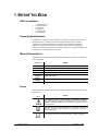
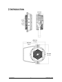
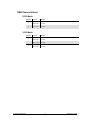
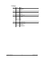
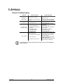
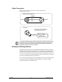
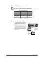
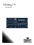
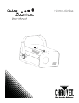
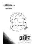
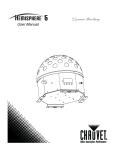
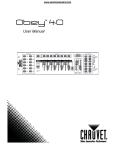
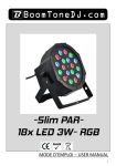
User Manual TABLE OF CONTENTS 1. BEFORE YOU BEGIN ................................................................................................................................................... 3 WHAT IS INCLUDED ................................................................................................................................................................................ 3 UNPACKING INSTRUCTIONS .................................................................................................................................................................... 3 MANUAL CONVENTIONS ......................................................................................................................................................................... 3 ICONS .................................................................................................................................................................................................. 3 SAFETY INSTRUCTIONS .......................................................................................................................................................................... 4 2. INTRODUCTION ........................................................................................................................................................... 5 PRODUCT OVERVIEW............................................................................................................................................................................. 6 3. SETUP .......................................................................................................................................................................... 7 AC POWER........................................................................................................................................................................................... 7 Power Linking........................................................................................................................................................................................................... 7 MOUNTING............................................................................................................................................................................................ 8 Orientation................................................................................................................................................................................................................ 8 Rigging ..................................................................................................................................................................................................................... 8 4. OPERATING INSTRUCTIONS .................................................................................................................................... 10 CONFIGURING THE STARTING ADDRESS ................................................................................................................................................ 10 CONTROL PANEL FUNCTIONS ............................................................................................................................................................... 10 MENU MAP ......................................................................................................................................................................................... 11 OPERATION ........................................................................................................................................................................................ 12 DMX Operation ...................................................................................................................................................................................................... 12 Master/Slave Mode (Sound-Active, Auto Mode) ................................................................................................................................................... 12 STANDALONE ...................................................................................................................................................................................... 13 Automatic ............................................................................................................................................................................................................... 13 Color Temperature Preset ..................................................................................................................................................................................... 13 Custom Color Temperature ................................................................................................................................................................................... 13 DMX CHANNEL VALUES ...................................................................................................................................................................... 14 2-CH Mode ............................................................................................................................................................................................................. 14 3-CH Mode ............................................................................................................................................................................................................. 14 7-CH Mode ............................................................................................................................................................................................................. 15 5. APPENDIX .................................................................................................................................................................. 16 GENERAL TROUBLESHOOTING .............................................................................................................................................................. 16 DMX PRIMER ..................................................................................................................................................................................... 17 FIXTURE LINKING (DAISY CHAIN) .......................................................................................................................................................... 17 DATA CABLING .................................................................................................................................................................................... 17 DMX Data Cable .................................................................................................................................................................................................... 17 CABLE CONNECTORS .......................................................................................................................................................................... 18 SETTING THE STARTING ADDRESS ........................................................................................................................................................ 18 3-Pin to 5-Pin Conversion Chart ............................................................................................................................................................................ 19 Setting up a DMX Daisy Chain .............................................................................................................................................................................. 19 GENERAL MAINTENANCE...................................................................................................................................................................... 20 RETURNS PROCEDURE ........................................................................................................................................................................ 20 CLAIMS .............................................................................................................................................................................................. 20 TECHNICAL SPECIFICATIONS ..................................................................................................................................... 21 CONTACT US ................................................................................................................................................................. 22 CHAUVET®, 2010, All Rights Reserved Information and specifications in this User Manual are subject to change without notice. CHAUVET® assumes no responsibility or liability for any errors or inaccuracies that may appear in this manual. Author: Anthony Chiappone Revision: 01 Release Date: 11-23-2010 1. BEFORE YOU BEGIN What is included 1 x SlimPAR™ Pro VW 1 x Hanging bracket 1 x Gel Holder 1 x Power Cord 1 x Warranty Card 1 x User Manual Unpacking Instructions Immediately upon receiving a fixture, carefully unpack the carton, check the contents to ensure that all parts are present, and have been received in good condition. Notify the shipper immediately and retain packing material for inspection if any parts appear damaged from shipping or the carton itself shows signs of mishandling. Save the carton and all packing materials. In the event that a fixture must be returned to the factory, it is important that the fixture be returned in the original factory box and packing. Manual Conventions CHAUVET® manuals use the following conventions to differentiate certain types of information from the regular text. MEANING CONVENTION [10] <Menu> A DIP switch to be configured A key to be pressed on the fixture’s control panel 1~512 A range of values 50/60 A set of values of which only one can be chosen Settings A menu option not to be modified (for example, showing the operating mode/current status) MENU > Settings A sequence of menu options to be followed ON A value to be entered or selected Icons This manual uses the following icons to indicate information that requires special attention on the part of the user. MEANING ICONS This paragraph contains critical installation, configuration or operation information. Failure to comply with this information may render the fixture partially or completely inoperative, cause damage to the fixture or cause harm to the user. This paragraph contains important installation or configuration information. Failure to comply with this information may prevent the fixture from functioning correctly. This paragraph reminds you of useful, although not critical, information. 1. Before You Begin 3 11/24/2010 4:15 PM Safety Instructions Please read these instructions carefully. It includes important information about the installation, usage and maintenance of this product. 1. Before You Begin Please keep this User Manual for future consultation. If you sell the unit to another user, be sure that they also receive this instruction booklet. Always make sure that you are connecting to the proper voltage, and that the line voltage you are connecting to is not higher than that stated on the decal or rear panel of the fixture. This product is intended for indoor use only! To prevent risk of fire or shock, do not expose fixture to rain or moisture. Make sure there are no flammable materials close to the unit while operating. The unit must be installed in a location with adequate ventilation, at least 20 in (50 cm) from adjacent surfaces. Be sure that no ventilation slots are blocked. Always disconnect from power source before servicing or replacing fuse and be sure to replace with same fuse source. Secure fixture to fastening device using a safety chain. Maximum ambient temperature (Ta) is 104° F (40° C). Do not operate fixture at temperatures higher than this. In the event of a serious operating problem, stop using the unit immediately. Never try to repair the unit by yourself. Repairs carried out by unskilled people can lead to damage or malfunction. Please contact the nearest authorized technical assistance center. Never connect the device to a dimmer pack. Make sure the power cord is never crimped or damaged. Never disconnect the power cord by pulling or tugging on the cord. Never carry the fixture directly from the cord. Always use the hanging/mounting bracket. Avoid direct eye exposure to the light source while it is on. 4 11/24/2010 4:15 PM 2. INTRODUCTION 2. Introduction 5 11/24/2010 4:15 PM Product Overview Control Panel (LED Display) DMX In Power In DMX Out Fuseholder Power Out Bracket Adjustment Knob Bracket Adjustment Knob Safety Hanging Bracket 2. Introduction 6 11/24/2010 4:15 PM 3. SETUP AC Power This fixture is auto-ranging and runs on 100~240 VAC, 50/60 Hz power. To determine the power requirements for a particular fixture, see the label affixed to the back plate of the fixture or refer to the fixture’s specifications chart. A fixture’s listed current rating indicates its average current draw under normal conditions. Always connect the fixture to a switched circuit. Never connect the fixture to a rheostat (variable resistor) or dimmer circuit, even if the rheostat or dimmer channel is used only as a 0 to 100% switch. Always connect the fixture to a circuit with a suitable electrical ground. Power Linking This fixture contains power linking via the Edison outlet located in front of the power input cable. Please see the diagram below for further explanation. The maximum quantity of SlimPAR™ Pro VW that may be linked is 22. Fixture #1 Fixture #2 Fixture #3 Additional power link out The power linking shown in this document is for the CHAUVET® North American version ONLY! Therefore, it is the customer’s responsibility to check with the Dealer/Distributor regarding power linking on the local version of the product. Connections and availability may change, depending on the power requirements and/or regulations of each country/region. 3. Setup 7 11/24/2010 4:15 PM Mounting Orientation The SlimPAR™ Pro VW may be mounted in any position provided there is adequate room for ventilation. Rigging Be sure that the structure can support the weight of the fixture. Please see the “Technical Specifications” section of this manual for a detailed weight listing. Mount the fixture securely. This may be done with a screw, nut and bolt, or a hanging clamp. The hole in each bracket is 13 mm in size. When rigging, consider routine maintenance and control panel access. Please see the following notes on installation. If the power link out is intended to be used with multiple fixture, take into account the length of each power cable, and mount the fixtures close enough to one another to accommodate for this. When aiming the fixtures, you may use the bracket adjustment knob(s). Loosen the knob(s), adjust to the desired angle, and then tighten the knob(s) by turning clockwise. Do not use tools for this step, as it may cause damage. Use the rubber feet to support the fixture in a sitting position. Safety cables must always be used. Bracket Adjustment Knob Bracket Adjustment Knob Safety 3. Setup 8 11/24/2010 4:15 PM Lens Assembly Replacement The SlimPAR™ Pro VW has an option available to replace the secondary LED optics, or lens assembly. This will alter the beam and field angles of the fixture. The wide angle lens assembly is installed at the factory. The narrow lens assembly is available as an optional accessory. Please see the steps below for instructions on replacing the lens assembly in the SlimPAR™ Pro VW. 1. 2. 3. 4. 5. 6. Remove the four Allen screws from the front trim ring with glass of the fixture. Use a #3 metric Allen wrench for this step. After removing the screws, the front cover will come off. Remove it. You now have access to the lens assembly. Use a Philips #2 screwdriver to remove the four screws that hold it in place. Carefully remove the lens assembly. The LEDs will now be exposed. Use caution to prevent damage. Place the new lens assembly in the fixture and reinstall the four Philips #2 screws. Put the front cover in place and reinstall the four Allen screws. Allen screw Allen screw Allen screw Allen screw Lens assembly Front cover 3. Setup 9 11/24/2010 4:15 PM 4. OPERATING INSTRUCTIONS Configuring the Starting Address The SlimPAR™ Pro VW fixture uses 7 DMX channels in its maximum setting. In this DMX configuration/personality, the highest channel that the fixture may be set to in order to function properly is 506. Any address higher than this will prevent access to all of the channels, while in this mode; however, if you desire to use one of the other DMX channels configurations (personalities), please consider the total DMX channels when selecting a DMX address. If this is your first time using DMX, we recommend reading the “DMX Primer” section in the “Appendix”. Control Panel Functions Access control panel functions using the four buttons located directly underneath the LED display on the included wired remote. BUTTON FUNCTION <MENU> Used to scroll through the current operating mode, as well as back out of the current menu option <ENTER> Used to select a move to the right in the menu map and select a value and store it to memory <UP> Used to select increasing advancement in the value <DOWN> Used to select decreasing advancement in the value MENU ENTER UP DOWN The Control Panel shows the current state of the unit. It is used to select the operating mode, as well as the sub-features. For a detailed layout of the control panel functions, please see the “menu map” section. 4. Operating Instructions 10 11/24/2010 4:15 PM Menu Map MAIN FUNCTION DMX Address SELECTION SUB-SELECTION Personality Dimming Curve Color Temperature Preset ~ ~ ~ Custom Static Color Auto Program DESCRIPTION DMX starting address selection 7-channel operating mode 3-channel operating mode: warm/cool white color temperature mixing with dimmer 2-channel operating mode: warm/cool white color temperature mixing Dimming curve: off Dimming curve: dim 1 Dimming curve: dim 2 Dimming curve: dim 3 White 1 White 2 White 3 White 4 White 5 White 6 White 7 White 8 White 9 ~ Combine warm and cool white to create a custom, static color temperature mix Strobe speed ( =no strobe) Program selection Run speed ~ ~ There is no strobing in the following modes: Channel DMX mode. 4. Operating Instructions 11 and . For full function control, use 7- 11/24/2010 4:15 PM Operation DMX Operation This is the operating mode which will allow for control with an external DMX controller. You must set the starting address for this mode. If this is your first time using DMX, then it is recommended that you refer to the “DMX Primer” section in the “Appendix” of this manual. Please see the instructions below to operate the fixture in this mode. 1. 2. 3. 4. 5. 6. 7. 8. 9. Plug a DMX controller into the fixture in a daisy chain configuration. Press <MENU> until the following appears on the LED screen: . Press <ENTER>. Using <UP> & <DOWN>, select the desired personality ( , , Press <ENTER>. Press <MENU> until appears on the LED screen. Press <ENTER>. Using <UP> & <DOWN>, select the desired DMX starting address ( Press <ENTER>. ). ~ ). Only connect 32 fixtures to a single DMX daisy chain! Master/Slave Mode (Sound-Active, Auto Mode) This mode allows a single unit, the master, to operate in one of the standalone modes, while one or more fixtures, slaves, synchronize their responses to the master. Master: The master fixture may be set in any of the STANDALONE modes listed in this user manual. Slave: 1. Set the slave fixture(s) to DMX mode at starting address 001. Only connect 31 slave fixtures when operating in this mode! 4. Operating Instructions 12 11/24/2010 4:15 PM Standalone This fixture has several options for operating without a DMX controller. Access these options via the control panel on the back of the fixture. Automatic This fixture has preprogrammed chases that may be triggered without a controller. Access these chases via the control panel on the back of the fixture. Please see the instructions below for details on entering this mode. 1. 2. 3. 4. 5. 6. 7. 8. 9. Remove any DMX controller from the fixture. Press <MENU> to select Auto Program ( ). Press <ENTER>. Using <UP> & <DOWN>, select one of the 5 programs. Press <ENTER>. Press <MENU> until ~ appears on the LED screen. Press <ENTER>. Using <UP> & <DOWN>, select the desired run speed (slow~fast) Press <ENTER>. Color Temperature Preset This fixture has preprogrammed, static color temperature presets that may be triggered without a controller. Access these chases via the control panel on the back of the fixture. Please see the instructions below for details on entering this mode. 1. 2. 3. 4. 5. Remove any DMX controller from the fixture. Press <MENU> to select Color Temperature Preset mode ( Press <ENTER>. Using <UP> & <DOWN>, select one of the nine presets. Press <ENTER>. ). Custom Color Temperature This fixture has the ability to accept a custom static color temperature setting. Access this via the control panel. Please see the instructions below for further explanation. 1. 2. 3. 4. 5. Press <MENU> until appears on the LED screen. Press <ENTER>. Using <UP> and <DOWN>, select the desired color. Press <ENTER>. Using <UP> and <DOWN>, select the desired color value ( ~ ). By selecting , the color will remain off. 6. Press <ENTER> to continue to the next color ( ). 7. Using <UP> and <DOWN>, select the desired color value ( ~ ). 8. Continue until the desired mix is obtained. The order of colors is warm white and cool white. 9. Press <ENTER> to continue to the strobe setting. 10. Using <UP> and <DOWN>, select the desired strobe value ( ~ ). By selecting , the strobe function will remain off. 11. Press <ENTER> to save the final color setting. This will move the selection to the following color. However, this is necessary to save the modification. 4. Operating Instructions 13 11/24/2010 4:15 PM DMX Channel Values 2-CH Mode CHANNEL VALUE FUNCTION 1 000 255 Warm White 0%~100% 2 000 255 Cool White 0%~100% 3-CH Mode 4. Operating Instructions CHANNEL VALUE FUNCTION 1 000 255 Master Dimmer 0%~100% 2 000 255 Warm White 0%~100% 3 000 255 Cool White 0%~100% 14 11/24/2010 4:15 PM 7-CH Mode 4. Operating Instructions CHANNEL VALUE FUNCTION 1 000 255 Master Dimmer 0%~100% 2 000 255 Warm White 0%~100% 3 000 255 Cool White 0%~100% 4 000 009 010 255 Strobe No function 1~20 Hz (slow~fast) 5 000 051 052 101 102 152 153 203 204 254 255 255 Auto Program No Function Auto 1 Auto 2 Auto 3 Auto 4 Auto 5 6 000 255 Auto Program Speed (only when CH.7 is between 052~255) 0%~100% (slow~fast) 7 000 051 052 101 102 152 153 203 204 255 Dimmer Speed Default dimmer speed Linear dimmer Non-linear dimmer 1 Non-linear dimmer 2 Non-linear dimmer 3 15 11/24/2010 4:15 PM 5. APPENDIX General Troubleshooting SYMPTOM Breaker/Fuse keeps blowing Device does not power up POSSIBLE CAUSE(S) Excessive circuit load Check total load placed on the electrical circuit. Short circuit along the power wires Check for a short in the electrical wiring (internal and/or external). No power Loose power cord Check for power on Mains. Check power cord Check Control Panel and unit addressing Check DMX cables Check polarity switch settings on the controller Check cable connections Replace DMX input Replace Main PCB Use only DMX compatible cables Install terminator as suggested. Install amplifier right after fixture with strong signal. Install an optically coupled DMX splitter after unit #32. Keep DMX cables separated from power cables or black lights. Wrong DMX addressing Fixture is not responding to DMX POSSIBLE ACTION(S) Damaged DMX cables Wrong polarity settings on the controller Loose DMX cables Faulty DMX interface Faulty Main PCB Non DMX cables Bouncing signals Long cable / Low level signal Loss of signal Too many fixtures Interference from AC wires If you still have a problem after trying the above solutions, please contact CHAUVET® Technical Support. 5. Appendix 16 11/24/2010 4:15 PM DMX Primer There are 512 channels in a DMX connection. A fixture capable of receiving DMX will require one or a number of sequential channels. The user must assign a starting address on the fixture that indicates the first channel reserved in the controller. There are many different types of DMX controllable fixtures and they all may vary in the total number of channels required. Choosing a start address should be planned in advance. Channels should never overlap. If they do, this will result in erratic operation of the fixtures whose starting address is set incorrectly. You can however, control multiple fixtures of the same type using the same starting address as long as the intended result is that of unison movement or operation. In other words, the fixtures will all respond exactly the same. DMX fixtures are designed to receive data through a daisy chain. A daisy chain connection is where the DATA OUT of one fixture connects to the DATA IN of the next fixture. The order in which the fixtures are connected is not important and has no effect on how a controller communicates to each fixture. Use an order that provides for the easiest and most direct cabling. Connect fixtures using shielded two conductor twisted pair DMX data cable with three pin XLR male to female connectors. The shield connection is pin 1, while pin 2 is Data Negative (S-) and pin 3 is Data positive (S+). Fixture Linking (Daisy Chain) You will need a daisy chain to run light shows of one or more fixtures using a DMX controller or to run synchronized shows on two or more fixtures set to a master/slave operating mode. The combined number of channels required by all the fixtures on a daisy chain determines the number of fixtures the data link can support. To comply with the EIA-485 standard, do not connect more than 32 fixtures on one daisy chain. Connecting more than 32 fixtures on one daisy chain without the use of a DMX optically-isolated splitter may result in deterioration of the digital DMX signal. Maximum recommended cable distance: 500 m (1640 ft) Maximum recommended number of fixtures on a daisy chain: 32 Data Cabling To link fixtures together you must obtain data cables. You can purchase CHAUVET® certified DMX cables directly from a dealer/distributor or construct your own cable. If you choose to create your own cable please use data-grade cables that can carry a high quality signal and are less prone to electromagnetic interference. DMX Data Cable Use a Belden© 9841 or equivalent cable which meets the specifications for EIA RS-485 applications. Standard microphone cables cannot transmit DMX data reliably over long distances. The cable must have the following characteristics: Type: shielded, 2-conductor twisted pair Maximum capacitance between conductors: 30 pF/ft Maximum capacitance between conductor and shield: 55 pF/ft Maximum resistance: 20 ohms/1000 ft Nominal impedance: 100 ~ 140 ohms 5. Appendix 17 11/24/2010 4:15 PM Cable Connectors Cabling must have a male XLR connector on one end and a female XLR connector on the other end. DMX connector configuration COMMON INPUT 1 3 2 DMX + DMX - 1 3 2 OUTPUT Terminator To avoid signal transmission problems and interference, it is always advisable to connect a DMX signal terminator. 1 3 2 120 ohm ¼ W resistor between pin 2 (DMX -) and pin 3 (DMX +) on the output of the last fixture Do not allow contact between the common and the fixture’s chassis ground. Grounding the common can cause a ground loop, and your fixture may perform erratically. Test cables with an ohm meter to verify correct polarity and to make sure the pins are not grounded or shorted to the shield or each other. Setting the Starting Address This DMX mode enables the use of a universal DMX controller device. Each fixture requires a start address from 1~512. A fixture requiring one or more channels for control begins to read the data on the channel indicated by the start address. For example, a fixture that uses six DMX channels and was addressed to start on DMX channel 100, would read data from channels: 100, 101, 102, 103, 104, and 105. Choose start addresses so that the channels used do not overlap, and note the start address selected for future reference. If this is your first time addressing a fixture using the DMX control protocol, we suggest jumping to the “Appendix” section and reading the heading “DMX Primer”. It contains very useful information that will help you understand its use. 5. Appendix 18 11/24/2010 4:15 PM 3-Pin to 5-Pin Conversion Chart If you use a controller with a 5-pin DMX output connector, you will need to use a 5-pin to 3-pin adapter. The chart below details a proper cable conversion: 3-PIN TO 5-PIN CONVERSION CHART Conductor 3-Pin Female (Output) 5-Pin Male (Input) Ground/Shield Pin 1 Pin 1 Data ( - ) signal Pin 2 Pin 2 Data ( + ) signal Pin 3 Pin 3 Not used Pin 4 Not used Pin 5 Setting up a DMX Daisy Chain 1. Connect the (male) 3-pin connector side of the DMX cable to the output (female) 3-pin connector of the controller. Universal DMX Controller 2. Connect the end of the cable coming from the controller which will have a (female) 3-pin connector to the input connector of the next fixture consisting of a (male) 3-pin connector. This drawing provides a general illustration of the DMX input/output panel of a lighting fixture. 3. Then, proceed to connect from the output as stated above to the input of the following fixture and so on. Continue the link 5. Appendix 19 11/24/2010 4:15 PM General Maintenance To maintain optimum performance and minimize wear, fixtures should be cleaned frequently. Usage and environment are contributing factors in determining frequency. As a general rule, fixtures should be cleaned at least twice a month. Dust build up reduces light output performance and can cause overheating. This can lead to reduced lamp life and increased mechanical wear. Be sure to power off fixture before conducting maintenance. Unplug fixture from power. Use a vacuum or air compressor and a soft brush to remove dust collected on external vents. Clean all lenses when the fixture is cool with a mild solution of glass cleaner or Isopropyl Alcohol and a soft lint free cotton cloth or lens tissue. Apply solution to the cloth or tissue and drag dirt and grime to the outside of the lens. Gently polish optical surfaces until they are free of haze and lint. The cleaning of external optical lenses and/or mirrors must be carried out periodically to optimize light output. Cleaning frequency depends on the environment in which the fixture operates. Damp, smoky or particularly dirty surroundings can cause greater accumulation of dirt on the unit’s optics. Clean with soft cloth using normal glass cleaning fluid. Clean the external optics at least every 20 days. Clean the fixture at least every 30/60 days. Always dry the parts carefully after cleaning them. Never spin a fan using compressed air. Returns Procedure Returned merchandise must be sent prepaid and in the original packing; call tags will not be issued. Package must be clearly labeled with a Return Merchandize Authorization Number (RMA #). Products returned without the RMA # will be refused. Call CHAUVET® and request an RMA # prior to shipping the fixture. Be prepared to provide the model number, serial number and a brief description of the cause for the return. Be sure to pack fixture properly; any shipping damage resulting from inadequate packaging is the customer’s responsibility. As a suggestion, proper UPS packing or double-boxing is always a safe method to use. CHAUVET® reserves the right to use its own discretion to repair or replace product(s). If you are given an RMA #, please include the following information on a piece of paper inside the box: 1) 2) 3) 4) 5) Your name Your address Your phone number The RMA # A brief description of the symptoms Claims Damage incurred in shipping is the responsibility of the shipper; therefore, the damage must be reported to the carrier upon receipt of merchandise. It is the customer's responsibility to notify and submit claims with the shipper in the event that a fixture is damaged due to shipping. Any other claim for items such as missing component/part, damage not related to shipping, and concealed damage, must be made within seven (7) days of receiving merchandise. 5. Appendix 20 11/24/2010 4:15 PM TECHNICAL SPECIFICATIONS WEIGHT & DIMENSIONS Length............................................................................................................ 3.4 in (87 mm) Width ......................................................................................................... 10.1 in (256 mm) Height ........................................................................................................ 11.2 in (285 mm) Weight ........................................................................................................... 6.3 lbs (2.8 kg) POWER Auto-ranging ................................................................................... 100~240 VAC, 50/60 Hz Power consumption @ 120 V ................................................ 39 W (0.6 A) max, 0.3 A inrush Power consumption @ 230 V ................................................ 39 W (0.3 A) max, 0.4 A inrush Power output..................................................................................................... 22 units max LIGHT SOURCE Type ........................................................................................................ high-powered LED Quantity ............................................................................ 36 (18 warm white, 18 cool white) Rating ........................................................................................... 1 W (350 mA), 50,000 hrs PHOTO OPTIC (NARROW) (OPTIONAL) Lux.................................................................................................................... 8,750 @ 1 m Beam angle......................................................................................................................17° Field angle .......................................................................................................................36° PHOTO OPTIC (WIDE) (INSTALLED) Lux.................................................................................................................... 6,050 @ 1 m Beam angle......................................................................................................................25° Field angle .......................................................................................................................44° COLOR TEMPERATURE Variable .................................................................................................... 2,300 K ~ 6,300 K INDOOR/OUTDOOR Rating ..................................................................................................... For indoor use only THERMAL Maximum ambient temperature ...................................................................... 104° F (40° C) CONTROL & PROGRAMMING Data input .............................................................................. locking 3-pin XLR male socket Data output ......................................................................... locking 3-pin XLR female socket Data pin configuration .............................................................pin 1 shield, pin 2 (-), pin 3 (+) Protocols..................................................................................................... DMX-512 USITT DMX Channels (user-configurable) ..............................................................................2, 3, 7 ORDERING INFORMATION SlimPAR™ Pro VW .................................................................................................. SPPVW WARRANTY INFORMATION Warranty ........................................................................................... 2-year limited warranty CONTACT US World Wide General Information CHAUVET® 5200 NW 108th Ave Sunrise, FL 33351 voice: 954.929.1115 fax: 954.929.5560 toll free: 800.762.1084 Technical Support CHAUVET® 5200 NW 108th Ave Sunrise, FL 33351 voice: 954.929.1115 (Press 4) fax: 954.929.5560 (Attention: Service) World Wide Web www.chauvetlighting.com