1
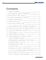
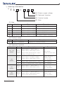
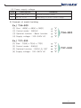
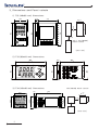
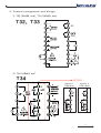
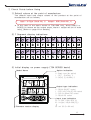
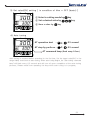
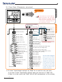
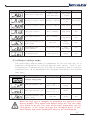
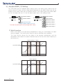
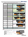
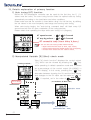
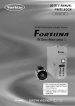
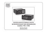
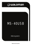
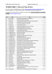
DIGITAL PID CONTROLLER
T30 SERIES PID Controller
User's Manual
T30 SE RIE S
T32/ T33/ T34/ T37/ T39
www.temcoline.com
DIGITAL PID CONTROLLER
Thank you for purchasing the T30 series from Temcoline.
The T30 series is a precision industrial controller that uses an
advanced 2 degree-of-freedom (DOF) algorithm.
The T30 series consists of 5 models, which are T32, T33, T34, T37,
and T39.
This manual explains the installation, the functions, the operation, and
the handling of the products.
Please read the manual thoroughly before using the products.
If any difficulties arise while using our products, please call our
customer service at +82-1588-5439.
Pay attention to the followings!
-
Use the products under the conditions specified in this manual.
Please heed the cautions and warnings listed in this manual.
The contents of the manual may be changed without notice.
The product is designed to be used installed on a control panel.
This manual is copyrighted, and may not be copied in part or in
whole without permission.
- The manufacturer takes no responsibility for direct or indirect damages
caused by careless operation or operation under unpredictable or
risky environments.
Safety requirements!
Safety requirements are intended to prevent accidents and dangers
through the proper use of the products, so please heed them at all
times.
The safety requirements are divided into "cautions" and "warnings",
which indicate the following.
WARNING
Serious injury or death may be caused
if instructions are not observed.
CAUTION
Failure to observe these instructions
may cause damage to the instrument
or some injury to the user.
2
www.temcoline.com
DIGITAL PID CONTROLLER
WARNING
1. Use a separate safety device when this product is used to control a
device that could harm lives or expensive property in the event of a
malfunction or a breakdown. (This may cause fires, deaths, or damage
to property.)
2. Do not use this controller at place where there are flammable or
explosive gas. (It may cause a fire or explosion.)
3. Before turning the power on, please check that wiring is
correct to the number of terminal. (It may cause a fire.)
4. Turn off the power during wiring and maintenance to avoid an
electric shock.
5. Do not touch the terminals when it is power on. (It may give an
electric shock.)
6. This controller must be mounted on the panel to avoid an
electric shock.
7. Do not attempt to disassemble, modify and repair.
CAUTION
1. Please conduct an inspection when water has entered the product.
(It may cause short circuits, fires, and malfunction.)
2. This controller should be used indoors.
(It may shorten the controller's life or give an electric shock.)
3. Observe the rated voltage and specification.
(It may cause a fire or shorten the controller's life.)
4. Be careful that any of foreign materials do not inflow into the
controller. (It may cause a fire or malfunction of the controller.)
5. Do not give direct vibration or shock to the controller.
(It may cause of malfunction of the controller.)
6. Do not use chemical detergent or solvent, but use a dry towel in
cleaning the controller.(It may cause an electric shock or a fire.)
7. Please check the polarity of power before wiring and connecting the
sensor. (It may cause an electric shock or explosion.)
3
www.temcoline.com
DIGITAL PID CONTROLLER
Contents
1 . Ordering Information
5
2. Input ranges & Output configuration
7
3. Dimensions & Panel cutouts
9
4. Terminal Arrangements & Wirings
12
5. Ratings & Specifications
14
6. Features & Function
15
7. Check points before using
16
8. Initial installation & Min. operation procedures
17
9. Entering into "set menu" & Setting method
18
10. Flow chart (Parameter structure)
21
11. Setting mode
22
12. Alarm(ALARM1, 2) setting
25
13. Details explanation of primary function
27
1) Auto tuning(AT) function
27
2) Manipulated variable(Mvn) check mode
27
3) Alarm(ALARM1, 2) function
28
4) Retransmission output
29
5) Input function
30
6) Selection function for Hysteresis
31
7) SV1, 2 set up control by external contact signal
32
8) Set value "LOCK" function
32
9) Error indication during operation
33
4
www.temcoline.com
DIGITAL PID CONTROLLER
1. Ordering Information
1)
T 3
(4) Power supply voltage
(3) Optional function
(2) Control mode
(1) Size
(1) Size
Code
2
3
4
7
9
Remarks
Model
Size
T32-SERIES
48(W) x 96(H) x 77(D)
No option (Basic function)
T33-SERIES
96(W) x 48(H) x 77(D)
No option (Basic function)
T34-SERIES
48(W) x 48(H) x 99(D)
Option : 0, 1, 2, 3
T37-SERIES
72(W) x 72(H) x 77(D)
Option : 0, 3
T39-SERIES
96(W) x 96(H) x 77(D)
No option (Basic function)
(2) Control mode
Code
Description
SINGLE : Standard
S
Remarks
Heating or Cooling control
(3) Optional function
Model
Code
Description
RELAY output 1,
T32, T33
SERIES
T34
SERIES
T37
SERIES
Basic
function
(0)
SCR(4~20mA), SSR(Voltage pulse) 1,
Basic
function
(0)
RELAY output 1 (ALARM or MAIN),
5
www.temcoline.com
RET(4~20mA Retransmission output)
No function
(Basic function S0x)
D.I(SV2, 3) External input
SCR(4~20mA), SSR(Voltage pulse) 1
Basic function +
Option code
(0 : No option)
1
RET(4~20mA Retransmission), Alarm 2
Ex.) T34-S10
3
D.I(SV2, 3) External input, Alarm output 2
Ex.) T34-S30
Basic
function
(0)
3
T39
SERIES
Remarks
Alarm output 2,
Basic
function
(0)
RELAY output 1,
Alarm output 2,
SCR(4~20mA), SSR(Voltage pulse) 1
Basic function +
Option code
(0 : No option)
D.I(SV2, 3), RET(4~20mA Retransmission)
Ex.) T37-S30
RELAY output 1,
Basic function +
Option code
(0 : No option)
Alarm output 2,
SCR(4~20mA), SSR(Voltage pulse) 1,
RET(4~20mA Retransmission)
DIGITAL PID CONTROLLER
(4) Power supply voltage
Description
Code
Remarks
General-purpose usage
0
100 ~ 240 V AC
1
24V AC or DC
Alternating or Direct current usage
2) Example of model building
Ex.) T34-S00
(1) Size : 48(W) x 48(H) x 99(D)
(2) Control mode : SINGLE
"4"
"S"
(3) Optional function : Basic function
(4) Supply voltage : 100~240V AC
"0"
"0"
T34-S00
Ex.) T37-S30
(1) Size : 72(W) x 72(H) x 77(D)
(2) Control mode : SINGLE
"7"
"S"
(3) Optional function : DI(SV1,2), RET
(4) Supply voltage : 100~240V AC
"3"
"0"
T37-S30
6
www.temcoline.com
DIGITAL PID CONTROLLER
2. Input ranges and Output configuration
1) Input ranges
Input type
※ The T30 series has multiple inputs, which may be set and changed by the user.
Input
K
J
E
Thermocouple
(T.C)
Setting
Code
Temperature range
1
-200 ~ 1370
2
-199.9 ~ 999.9
15
-200 ~ 1000
3
-199.9 ~ 999.9
16
-200 ~ 1000
4
-199.9 ~ 999.9
-199.9 ~ 400.0
T
5
R
6
0 ~ 1700
B
7
400 ~ 1800
S
8
0 ~ 1700
L
17
-200 ~ 900
9
-199.9 ~ 900.0
N
10
-200 ~ 1300
U
11
-199.9 ~ 400.0
C (W5)
12
0 ~ 2300
D (W3)
13
0 ~ 2400
J Pt 10 0Ω
(JIS, KS)
20
22
-200 ~ 500
Pt 10 0Ω
(DIN, IEC)
21
-199.9 ~ 640.0
23
0~100 mV DC
33
Voltage
-10~20 mV DC
(V DC/mV DC)
32
RTD
1~5 V DC
Current
4~20 mA DC
Accuracy
Remarks
* F.S is max. value
to min. value of
each range.
±0.3% of
F.S + 1 Digit * Digit is minimum
of display.
-199.9 ~ 500.0
-200 ~ 640
0 ~ 100 mV DC
-10 ~ 20 mV DC
30
1~5 V DC
30
When using current input,
use the resistor 250 Ω
on input terminal.
※ When using 1~5V input
(30), the interior jumper
switch must be relocated.
※ How to change the interior switch when using 1~5V input
①①Remove
or take
out
Remove plate
the jumper
cover
the
main
cover. of the T30,
on the
underside
or remove the rear case.
7
www.temcoline.com
MULT-IN
MODE
OTHER TYPES
IN 1~5V
MODE
1~5V DCONLY
INPUT ONLY
Move the
andjumper
insert using
the
②②Detach
jumper that
pulledit by
tweezers
and move
to
tweezers.
the
1-2 pins to the left.
③Once
Relocated
as
③
this hasjumper
been comabove and
attach
plate
pleted,
put the
jumper
or mounted
cover
back on,cover.
as shown
on the picture above.
DIGITAL PID CONTROLLER
2) Output configuration
※ The figure on the left uses
the terminal socket of
T37-S30 as an example
to illustrate the output
response relationship.
The T30 series
has multiple outputs.
General
type
T30-SXX
Setting
number Relay output
OUTPUT-1 (ALARM 1,2)
OUTPUT-1
SSR/SCR OUTPUT
AL1 output AL2 output SCR output
SSR output SCR output
0
OUT(ON/OFF) ALM1(34-S0x)
-
1
ALM1(34-S0x)
OUT(PID)
-
2
ALM1(34-S0x)
-
OUT(PID)
RET
3
OUT(PID)
ALM1(34-S0x)
-
RET
RET
ALARM1
ALARM2
RET
(1) Summary and explanation of output settings
Relay output of ON/OFF control [ Output setting number : 0 ]
This is a simple on/off control, mainly used to control cooling devices.
SSR output of PID control (Voltage pulse) [ Output setting number : 1 ]
This is the most widely used setting, and the default value at the point of manufacture.
SCR output of PID control (4~20mA current output) [ Output setting number : 2 ]
This setting is used mainly with thyristor power regulator (TPR) modules,
and is capable of precision control.
Relay output of PID control [ Output setting number : 3 ]
This is the most cost-efficient method of implementing PID control and is used mainly
with magnetic switches (electric switches). However, it may wear the contact point,
and is difficult to use in places that require fast response.
(2) Alarm output of T34(48x48) basic type(S00)
1(SSR) or 2(SCR)
0(ON/OFF)
or 3(RELAY)
ALARM1
output
ALARM1
output
Control output
Control output
※ It is only for T34-S00!
With the basic model of T34 (48x48), caution is required when using it alarm output.
When control output is being used as a relay, the alarm output will be SSR output
(voltage pulse). In this case, use SSR or alarm option (S10, S30) enabled models.
8
www.temcoline.com
DIGITAL PID CONTROLLER
3. Dimensions and Panel cutouts
1) T32 (48x96 mm) Dimensions
10.0
77.0
±0.5
45±0.5
45
±0.5
92
92±0.5
91.0
96.0
96.0
Min.
20
20 이상
48.0
30 이상
Min.
30
T32 // T33
T33 (48
× 96)
T32
(96x48)
Panel cutouts
판넬 가공치수
(Unit:
(단위 : mm)
mm)
2) T33 (96x48 mm) Dimensions
77.0
48.0
48.0
43.6
10.0
96.0
3) T34 (48x48 mm) Dimensions
8.8
48.0
T34 (48x48) Panel cutouts
99.0
+0.5
45 +0.5
−0
45 -0
45
−0
44.9
48.0
48.0
17 이상
Min.17
+0.5
+0.5
45 -0
17 이 상
Min.17
(단위 :mm)
mm)
(Unit:
9
www.temcoline.com
DIGITAL PID CONTROLLER
4) T37 (72x72 mm) Dimensions
9.0
72.0
T37(72
(72x72)
Panel
cutouts
가공치수
× 72) 판넬
T37
77.0
±0.5
68±0.5
68
67.0
72.0
72.0
±0.5
68
68 ±0.5
20 이상
Min.
20
30 이상
Min.
30
(단위
(Unit:: mm)
mm)
5) T39 (96x96 mm) Dimensions
96.0
77.0
91.0
96.0
96.0
10.0
±0.5
92
92±0.5
92±0.5
92 ±0.5
T39T39
(96(96x96)
× 96)
Panel cutouts
판넬 가공치수
30Min.
이상30
20 이상
Min. 20
(단위 (Unit:
: mm)mm)
10
www.temcoline.com
DIGITAL PID CONTROLLER
6) Installation
(1) T34-SERIES
① Bore a hole in the panel, referring to the panel cutouts on the previous page.
② Insert this device into the front of the panel.
③ From the rear of controller, slide the bracket over the housing.
④ Push the bracket in until the device has been fixed securely onto the panel.
⑤ Secure using screws on the two locations at top and bottom as shown on
Figure 2.
Fixi
ng
scre
w
Dire
ct
Turn
screw3-4
3-4
Turn the
the screw
times
after contact
contact
times after
with
panel.
with panel.
ion
[[ Picture
figure1 1] ]
Picture 22 ] ]
[ [ figure
(2) T32 / T33 / T37 / T39-SERIES
① Bore a hole in the panel, referring to the panel cutouts on the previous page.
② Insert this device into the front of the panel.
③ Insert 2 brackets, one each on the B/K holes on the top and the bottom
of the device.
④ Secure using screws on the two locations at top and bottom.
Hole
of구멍
fixing screw
고정나사
B/K 구멍 hole
Bracket
[ figure
1 ]B/K
Top고정
side위치
[그림
1] 윗면
11
www.temcoline.com
Hole of fixing
screw
고정나사
구멍
Bracket
hole
B/K 구멍
[ figure
2 ] Bottom
side
[그림
2] 아래면
B/K 고정
위치
나사 조임은 B/K 이
Turn the screw
판넬에 닿은 후 2~3
2-3 times after
회전
까지로
contact
with합니다.
panel.
[ figure
3 ] Fixing
[그림
3] 아래면
장착completion
완료상태
DIGITAL PID CONTROLLER
4. Terminal arrangements and Wirings
1) T32 (48x96 mm), T33 (96x48 mm)
T32, T33
2) T34 (48x48 mm)
T34
OPTION
Option 1
(T34-S1x)
Option 3
(T34-S3x)
12
www.temcoline.com
DIGITAL PID CONTROLLER
3) T37 (72x72 mm)
Option 3
(T37-S3x)
T37
Option 3
(T37-S3x)
OPTION
4) T39 (96x96 mm)
T39
※ Terminal explanation (T39-S00)
Terminal
: OUT1 only for output
selection no. 0, 3 (Relay output) mode.
Terminal
: O U T 2 o n l y fo r o u t p u t .
selection no. 1, 2 (SSR, SCR output) mode.
Terminal
: RET(Retransmission 4~20mA)
or for power of sensor SPS. (DC 15V)
Terminal
: Power supply terminal.
Terminal
: Alarm1 output terminal.
Terminal
: Alarm2 output terminal.
Terminal
: The external D.I input
terminal may be used when (DIS=ON), and
the target value may be controlled. (SV1, SV2)
Terminal
13
www.temcoline.com
: Input terminals.
DIGITAL PID CONTROLLER
5. Ratings and Specifications
Model
T30-SERIES
Power supply
Rating 100~240V AC 50~60Hz (voltage operating range: 85~265V AC)
※ Option: Rating 24V AC or DC (voltage operating range: 20~28V DC)
Power consumption
5VA (Max.)
Input Type
TC: K, J, T, E, R, B, S, L, N, U, C(W5), D(W3)
Platinum RTD: KPt100(KS), JPt100(JIS), Pt100(DIN)
Current input(A): 4~20mA DC
Voltage input(V): 1~5V DC, -10~20mV DC, 0~100mV DC
Display Accuracy
±0.3% of FS +1 Digit
Input Impedance
Current input (250Ω), Voltage input (TC included) ≥ 1MΩ
(RTD line resistance : ≤ 10Ω, when 3-line resistance are the same)
Input sampling period 50~250ms (variable according to SG-PID algorithm)
Voltage
(S.S.R)
1c 250V AC, 3A(resistance load) electric lifespan ≥ 100,000
(time proportional PID output or ON/OFF output)
DC15V 25mA (built-in short protection circuit)
Voltage pulse (time proportional PID output)
Current
(S.C.R)
4~20mA DC, load impedance ≤ 600Ω (continuous PID output)
Relay
Control
Output
Control Method
Super 2 degree-of-freedom PID (SG-PID algorithm),
Auto-Tuning
Multi SV Input (D.I)
ON : ≤ 1KΩ, OFF : ≥ 100KΩ (external control SV1,2)
4~20mA DC, load impedance ≤ 600Ω resolution 1/4,600
Retransmission Output PV(process value), SV(set value), MV(manipulated variable[%]),
SPS(sensor module power supply)
Alarm
output
ALARM 1, 2
1a 250V AC 3A (resistance load)
(LBA common) 20 type of independent event output & Control loop break alarm
Ambient temperature
and Humidity
-10~50℃ / relative humidity 25~85% RH
(but with neither condensation nor freezing)
Weight
T32, T33, T37 : 230g
T34 : 140g
(Bracket, Accessories included) ※ + 30g, if options are added
T39 : 320g
14
www.temcoline.com
DIGITAL PID CONTROLLER
6. Features and Function (ex. T34 SERIES)
①
(PV)
① Process
Process value
value (PV)
display
Display (Red
(Red color)
color)
②
② Auto
Auto tuning
tuning(AT)
(AT) lamp
lamp
③
③ Set
Set value
value (SV)
(SV)
display
Display (Green
(green color)
⑩
⑩ Set
Set value
value Up
Up key
⑨
⑨ Set
Set value
value Down
Down key
key
⑧
⑧ Shift
Shift key
key
⑦
⑦ Storage
Storage && Function
function key
key
④ Control
Controloutput
outputlamp
lamp
④
⑤ SV2
SV-2display
displaylamp
lamp
⑤
⑥
⑥ Alarm
Alarm output
outputlamp
lamp
※ Description
Name
Function
① Process value
Display the process value. (red color)
② Auto tuning lamp
Flash every 0.5 second during auto tuning.
③ Set value display
Display the set value, codes, and modes.
④ Control output lamp
Lights when the control output is ON.
⑤ SV2 display lamp
Lights when the SV2 is displayed.
⑥ Alarm output lamp
Lights during the alarm is ON.
Function key
Use to move the menus, to store, and to operate.
⑧
Shift key
Use to shift the digits.
⑨
Set value down key
Use to decrease set value and to move the menu.
⑩
Set value up key
Use to increase set value and to move the menu.
⑦
SET
15
www.temcoline.com
DIGITAL PID CONTROLLER
7. Check Points before Using
1) Default values at the point of manufacture
The default input and output values of the product at the point of
manufacture are as follows.
Input : K-Type (Code No. 1)
Output : SSR (Code No. 1)
※ In the case of the basic model of T34-S00 only, when SSR(1) or
SCR(2) is chosen as the output mode, Alarm 1 output will be in main
relay. (Refer to page 8 for details.)
2) 7 Segment display indications
3) Initial display on power supply (T34 SERIES basis)
Model Name
Option indication
0 : Basic type (No option)
1 : RET, ALARM1, 2
3 : DI(SV1, 2), ALARM1, 2
Output type indication
0 : RELAY ON/OFF control
1 : SSR (VOLT-PULSE) PID control
2 : SCR (4~20mA) PID control
3 : RELAY PID control
Input type indication
01 : K-Type (-200~1370 ℃)
02 : K-type (-199.9~999.9 ℃)
Firmware version display
33 : mV DC (0~100 mV)
16
www.temcoline.com
DIGITAL PID CONTROLLER
8. Initial installation and Minimum operation procedures
The following are the instructions for initial installation and minimum operation
procedures. Please read the contents of this manual, including the general
functions outlined here, as thoroughly as possible before operating the device.
1) Check the external wiring diagram and specifications.
(power supply and terminal arrangement)
2) Check input and output specifications!
The default setting for the T30 series at the point of manufacturer are as follows.
Input : K(CA) Type (setting code 1)
Output : SSR mode (setting code 1)
If you wish to change the input or the output type, please select the
option you desire on the input group and the output group menus.
※ The input type settings must be configured first before changes to other
set values are made.
When the input type is changed, all other parameters (set values) are
reverted to their factory default.
3) Select the desired set value (SV).
4) Please set auto-tuning or P, I, D values to suit the operating environment.
Auto-tuning is recommended except under special circumstances.
17
www.temcoline.com
DIGITAL PID CONTROLLER
9. Entering into "set menu" and Setting method
1) Input & Output type setting
Temcoline products are universalized input and
output. Please set up input and output type firstly
and use when install our unit.
The method for input and output setting menu
before auto-tuning.
① Press
SET
+
key more than 3 seconds, Entering into
input & output setting menu.
② Input type setting : Select the desired input sensor type.
(setting code 1~33 / refer to P7, Input ranges)
INPUT(T.C)
K
E
TEMP. RANGE
INPUT(RTD)
1
-200 ~ 1370
2
-199.9 ~ 999.9
-200 ~ 1000
-199.9 ~ 999.9
J P t 1 0 0Ω
(JIS, KS)
-200 ~ 1000
P t 1 0 0Ω
(DIN, IEC)
15
3
16
J
4
-199.9 ~ 999.9
T
5
-199.9 ~ 400.0
R
6
0 ~ 1700
B
7
8
400 ~ 1800
S
17
L
SET
CODE
-200 ~ 900
9
10
-199.9 ~ 900.0
N
U
11
-199.9 ~ 400.0
12
0 ~ 2300
13
0 ~ 2400
-199.9 ~ 500.0
22
-200 ~ 500
21
-199.9 ~ 640.0
23
-200 ~ 640
CODE
0 ~ 100 mV DC
33
-10 ~ 20 mV DC
32
1 ~ 5 V DC
-200 ~ 1300
D (W3)
TEMP. RANGE
20
INPUT(V DC/mV DC)
0 ~ 1700
C (W5)
CODE
4 ~ 20mA DC
( U se 2 50Ω re si st o r . )
30
SET
③ Output type setting : Select the desired output type.
(setting code 0~3 / refer to P8, Output Configuration)
SE T TING
CODE
CONTROL OUTPUT
0
RELAY ON/OFF CONTROL
1
SSR (Volt-Pulse) P.I.D CONTROL
2
SCR (4~20mA) P.I.D CONTROL
3
RELAY P.I.D CONTROL
SET
SET
④ Manipulated Variable Display setting [%]
It works when display the manipulated variable (0~100%) at
operating menu.
18
www.temcoline.com
DIGITAL PID CONTROLLER
2) The processing for input/output setting menu after auto-tuning
After auto-tuning has done of T30 series models, to avoid any user's mistake,
input/output setting menu is restricted automatically. But you can change input/
output by following ways. However, unit will be returned to factory default when
changed input type.
While normal using our products,
the method for input/output setting
menu after auto-tuning.
<Initial setting menu>
①
SET
+
more than 3 sec.
②
IOSE=ON
Return to the
operating menu.
(Will return
automatically)
③
SET
+
more than 3 sec.
<In/output setting menu>
※ Press SET +
more than 3 seconds at the inital set.
(before running auto-tuning)
19
www.temcoline.com
DIGITAL PID CONTROLLER
3) Set value(SV) setting [ in condition of Mvn = OFF (basic) ]
① Enter to setting mode by
② Set a desired value by
③ Store a value by
SET
SET
key
key
key
4) Auto tuning
AT operation start
:
SET
AT stop by perforce :
SET
+
+
0.5 second
0.5 second
AT command lamp (flash every 0.5sec.)
Auto-tuning is required before operating for the first time. Set the target value(SV) in the
range mainly used and run auto-tuning. When auto-tuning begins, the "auto-tuning command
lamp" will flash every 0.5 second and will turn off upon completion of the auto-tuning
process. Please refrain from operating the keys while auto-tuning is in progress.
20
www.temcoline.com
DIGITAL PID CONTROLLER
SET +
0.5 sec.
If the device is left idle for
approximately 50 se c onds
after entering a setting mode
other than the operation mode
it wil return automatically to
the operation mode.
Entering into in/output
setting mode
+ more than 3sec.
SET
Set value 1 (SV1)
+
( IOSE = ON )
3 sec.
SET
ON
Enable of
In/out setting
3 sec.
sec.
3
SET
〈 Initial set 〉
SET
SET
< General set mode >
3 sec.
SET
Output type selection
Lowest limit
Set value of alarm 1
sec.
3 sec.
Input type selection
Highest limit
Set value 2 (SV2)
+3
〈 In/Out set mode 〉
SET
3 sec.
3 sec.
SET
Mainpulated
Variable [%]
Input digital filter
SET
Set value of alarm 2
Input correction
Select of (SV1 or SV2)
number
Input high correction
(On voltage input)
※ in/output setting mistake
prevention system
Input unit (Fixed ℃)
Proportional band (℃)
Decimal point positioning (On voltage input)
Integral time (sec.)
Set highest scale (On voltage input)
Differential time (sec.)
Set lowest scale (On voltage input)
Manual reset [%]
(Integral time OFF only)
Output action selection (Reverse/Direct action)
REV. (Heating), DIR. (Cooling)
Type of alarm 1
Cycle time of output
(SSR or Relay)
Type of alarm 2
Hysteresis
(ON/OFF Control)
Hysteresis of alarm 1
Type of hysteresis
(ON/OFF Control)
Hysteresis of alarm 2
Control loop break alarm
Delay time of alarm 1
Highest limit
of retransmission
Delay time of alarm 2
External contact input
ON/OFF switch
Retransmission type
or SPS selection
Lowest limit
of retransmission
SET
Set of menu lock
SET
The full menu diagram
above shows all control
and setting menus on the
T30 series, but during actual
operations the menus that are
the most relevant to the situation
according to the options and
the operation mode, providing
a simpler user interface while
retaining functionality.
※ To enter "Input/Output settings" by "IOSE" On is valid for only one time.
If you want to enter "Input/Output settings" again you must turn on "IOSE" first.
If there is no Key action the "IOSE" will be OFF automatically in 50 seconds.
21
www.temcoline.com
Setting mode
AUTO TUNING...
Operation mode
10. Flow Chart (Parameter structure)
DIGITAL PID CONTROLLER
11. Setting mode
1) General setting mode
The general setting mode is for changing environment parameters on ad hoc basis
and also for tuning performance enhancement and configuring other functionalities.
Display
Description
Setting range
Condition Initial value
Display general setting
mode
-
-
-
Set value 1 (SV1) setting
EU (0 ~ 100 %)
D.I Option
in use
EU (0 %)
Set value 2 (SV2) setting
EU (0 ~ 100 %)
D.I Option
in use
EU (0 %)
Set value of alarm 1 (AL1)
EU (0 ~ 100 %)
Use Alarm 1
EU (100 %)
Set value of alarm 2 (AL2)
EU (0 ~ 100 %)
Use Alarm 2
EU (0 %)
Selection of (SV1, 2) number
1/2
Always
1
SV1, 2 proportional band (P)
0 ~ 999.9 ℃
PID control
20.0 ℃
SV1, 2 Integral time (I)
OFF / 1 ~ 6000 sec.
PID control
240 sec.
SV1, 2 Differential time (D)
OFF / 1 ~ 6000 sec.
PID control
60 sec.
SV1, 2 Manual reset (MR)
-5.0 ~ 105.0 %
Integral time
OFF
50.0 %
1 ~ 1000 sec.
PID control
(SSR or RELAY)
2 sec.
Hysteresis (ON/OFF control)
EUS (0 ~ 100 %)
ON/OFF
control
EUS (0.5 %)
Select the operational method
of Hysteresis
HALF / NORMAL
ON/OFF
control
NORMAL
Cycle Time (P.I.D Control Only)
Control loop break alarm (LBA)
Highest limit of retransmission
(RET.H)
lowest limit of retransmission
(RET.L)
ALARM1
OFF / 1 ~ 9999 sec.
No. 21 selection
Use
TC/RTD : _IN.H~_IN.L
retransmission
DCV IN : _SL.H~_SL.L
and select
( But, RET.H > RET.L )
PV or SV
480 sec.
EU (100 %)
EU (0 %)
22
www.temcoline.com
DIGITAL PID CONTROLLER
※ EU : An engineering unit in compliance with the input range
Ex.)
Input
selection
no.
: 01 (K-TYPE)
ex) Input
selection
no. : 01
(K-TYPE)
EU
0 % = -200
EU 100 % = 1370
EUS
0 %=0
EUS 100 % = 1570
INPUT -200
EU
INPUT -200
(0)
EUS
0
1370 [℃]
0
( 200 )
1370 [℃]
( 1570 )
0
100 [%]
0
100 [%]
2) Initial setting mode
The initial setting mode is for setting up initial parameters and configuration
for overall control and functionalities activation that are rarely changed after
the initial setup.
Display
Description
Setting range Condition Initial value
Initial set mode (ORG.N)
-
-
-
ON / OFF
Always
OFF
Within input range
(See input type and
range)
But, _IN.H > _IN.L
Always
Set input digital filter value
(_FLT)
OFF / 1~120 sec.
Always
OFF
Input value correction (_INS)
EUS (-100.0~100.0 %)
Always
EUS (0.0 %)
Correcting upper limit(Gain) of
EUS (-100.0~100.0 %)
input (_ING)
On voltage
input
EUS (0.0 %)
Input temperature unit selection
(Fixed Celsius)
℃ / ℉
TC or RTD
input
℃
Select the decimal point
position in Voltage input mode
(_DPP)
0 ~ 3
I/O setting entry switch
(IOSE)
Set highest input range
(_IN.H)
Set lowest input range
(_IN.L)
Free scale upper limit set
(voltage input mode)
Free scale lower limit set
(voltage input mode)
Output action selection
Select alarm 1 output type
23
www.temcoline.com
-1999 ~ 9999
But , SL-H > SL-L
Decimal point
positioning by _DPP
1370
-200
1
Voltage or
4~20mA
input mode
only
100.0
0.0
REV (Heating),
DIR (Cooling)
Always
REV (Heating)
OFF / 1 ~ 21(LBA)
(See alarm type)
Always
1
DIGITAL PID CONTROLLER
Display
Description
Setting range
Condition Initial value
OFF / 1 ~ 20
(See alarm type)
Using alarm
1, 2 option
2
Hysteresis of alarm 1 output
EUS (0.0 ~ 100.0 %)
Using alarm1
(1~20)
EUS (0.5%)
Hysteresis of alarm 2 output
EUS (0.0 ~ 100.0 %)
Using alarm2
EUS (0.5%)
Delay time of alarm 1
OFF / 1~240 sec.
Using alarm1
OFF
Delay time of alarm 2
OFF / 1~240 sec.
Using alarm2
OFF
OFF / ON
Using
DI option
OFF
Retransmission type
or SPS selection
PV/ SV/ MV/ SPS
Using
RET option
PV
Set data protection
OFF/ ON/ ALL
Always
OFF
Select alarm 1 output type
External contact input (SV1, 2)
ON/OFF switch
3) In/Output setting mode
The input/output setting mode is a parameter for the first time use. It's a
hardware configuration so requires special user caution. That is, the
configuration is determined by the type of equipment and it must be
configured first. (※ all parameters are initialized according to the entered
input type.)
Display
Description
In/output setting mode
Setting range
Condition Initial value
-
-
-
Input type selection (_InP)
1 ~ 33
(refer to P7, 2. 1)
Always
1
Output type selection (_out)
0~3
(refer to P8, 2. 2)
Always
1
Manipulated variable (_Mvn)
Display setting
OFF / ON
Always
OFF
When
input type
type isischanged,
changed,
parameters
reverted
to their
When the
the input
allall
parameters
areare
reverted
to their
factory defaul
factory
default.
before
the T30,
This means
that This
beforemeans
using that
the T30,
the using
input type
needsthe
to input
be set first, afte
type
needs
to
be
set
first,
after
which
other
parameters
can
which other parameters can be configured. If the input settings are be
changed whil
configured.
If theand
input
areneed
changed
while in use,
in use, auto-tuning
othersettings
parameters
to be reconfigured.
auto-tuning and other parameters need to be reconfigured.
24
www.temcoline.com
DIGITAL PID CONTROLLER
12. Alarm(ALARM1, 2) Setting
The T30 series has two separate alarm outputs, and in the setting group, alarms may be
chosen among 21 types, and the dead band (hysteresis) for the alarm output may be set.
Please find the alarm code with the desired function in the "Alarm types and codes table"
on the next page and use it to set the alarm output type in the settings mode.
Set value of alarm 1
〈General set mode〉
SET
Set value of alarm 2
Type of alarm 1
〈Initial set mode〉
3 sec.
3
sec.
SET
+
Type of alarm 2
3
3 sec.
sec.
Hysteresis of alarm 1
Loop break
Loop
breakalarm
alarm
Hysteresis of alarm 2
*Type
21)
* Typeof
of alarm
alarm 11 (When _A1.t == 21)
Delay time of alarm 1
This
LBA may
may be
beset
setonly
onlythrough
throughalarm
alarm1 output
1 output.
This means
means that
that LBA
Delay time of alarm 2
1) Hold function
When a low alarm is set and during temperature is rising, an unnecessary low alarm
may be happen. The hold function may be used to eliminate such problems.
The hold function allows the low alarm to be ignored automatically until the
temperature rises above the alarm threshold level for the first time when electricity is
first turned on.
Hold function : None
PV
Low limit alarm
Power ON
Alarm output
ON
OFF
ON
OFF
Hold function
PV
Low limit alarm
Power ON (HOLD)
Alarm output
25
www.temcoline.com
OFF
OFF
ON
OFF
DIGITAL PID CONTROLLER
2) Alarm output type and Selection code
CODE NO.
ALARM TYPE
01
Absolute value upper-limit
09
(Inverted output)
11
with hold function
19
with hold function (Inverted)
02
Absolute value lower-limit
10
(Inverted output)
12
with hold function
20
with hold function (Inverted)
03
Upper-limit deviation
05
(Inverted output)
13
with hold function
15
with hold function (Inverted)
Lower-limit deviation
06
(Inverted output)
14
with hold function
16
with hold function (Inverted)
17
08
18
21
Upper & Lower-limit
deviation with hold
Upper & Lower-limit
deviation in range
Upper & Lower-limit
deviation in range
with hold
Loop break alarm (LBA)
ON
ON
OF F
Low
ON
High
Alarm setting value
When temperature
is falling
When temperature
is rising
ON
OFF
OF F
ON
H yst eresis
OFF
ON
Low
High
Alarm setting value
<Negative temp. value setting> <Positive temp. value setting>
When temperature is
OFF
falling
When temOF F
perature is
rising
H yst eresis
ON
OFF
H yst eresis
ON
OFF
ON
-
Low
ON
OFF
ON
OF F
Temperature
High
-Alarm SV
Low
ON
High
Alarm
setting value
SV
<Negative temp. value setting> <Positive temp. value setting>
When temperature is
falling
When temperature is
rising
Temperature
Upper & Lower-limit
deviation
OFF
H yst eresis
OFF
Temperature
04
07
ALARM OUTPUT OPERATION
When temperature
is falling
When temperature
is rising
ON
OF F
H yst eresis
-
When temperature
is falling
When temperature
is rising
Temperature
ON
Low
Alarm
OF F
SV
High
ON
ON
OFF
ON
H yst eresis
ON
Low
When temperature
is falling
When temperature
is rising
ON
OFF
Alarm
OFF
ON
OF F
High
Alarm
SV
OF F
OFF
ON
H yst eresis
ON
OF F
Temperature
OFF
ON
High
SV -Alarm
OFF
OFF
H yst e re s i s
ON
OFF
ON
Low
ON
OF F
ON
Low
SV
Alarm
OFF
Alarm
High
Refer to P28, (2) LBA!
When alarm type reverse-correspondence is selected for alarm type and code,
please be aware that when the alarm lamp turns on, the contact output will be off.
■ Example of Alarm output 1 setting
Alarm type
(Upper-limit deviation) = 03
Hysteresis (Dead band) = 2 ℃
Alarm setting value = 20 ℃
118℃
118 ℃
When temperature
OFF
is falling
When temperature
OFF
is rising
OF F
ON
ON
120120℃
℃
OF F
ON
ON
Hysteresis (2 ℃) Hysteresis (2℃)
OFF
ON
ON
OFF
Temperature
Low
High
100Low
℃ 20100℃
℃
20℃
High
When
Set(SV)
Value
(SV)
( When Set
value
= 100
℃ =) 100℃ 26
www.temcoline.com
DIGITAL PID CONTROLLER
13. Details explanation of primary function
1) Auto tuning (AT) function
Before the PID temperature controller can be used for the first time, the P, I, D
values must be tuned. The auto-tuning function finds the optimal value by tuning
automatically according to the load factor and other conditions.
Please make sure that the controller is tuned before using it for the first time, by defining
the set values in the most frequently used range and running auto-tuning.
When auto-tuning begins, the "auto-tuning command lamp" will flash every 0.5
second and will turn off upon completion of the tuning process.
Please refrain from operating the keys while auto-tuning is in progress.
AT operation start
:
SET
AT stop by perforce :
SET
+
+
0.5 second
0.5 second
AT
lamp
(flash
every every
0.5sec.)0.5sec.)
AT command
command
lamp
(flash
※ Do
use auto
autotuning
tuningunder
underbelow
below
Process.
Do not use
Process.
- Rapid
control
Process
such
as Flow,
control.
- Rapid
control
Pr ocess
such
as Flow,
inputinput
control.
Process
which
should
not
ON/OFF
output
even aatemporary.
temporary.
- Process which should not ON/OFF output even
- Process which should not over load at control.
- Process which should not over load at control.
2) Manipulated Variable [%] (Mvn) check mode
〈 Setting method 〉
"Mvn [%] check function" displays the control output
“Mvn [%] 확인기능”은
“Mvncan
[%] check
function”by
displays
the control
[%], which
be viewed
pressing
the " output
SET " key
[%], which can be viewed by pressing
the “ SET ” key
기본운전
모드에서 SET
while operating in default operation mode
and is shown
while operating in default drive mode and is shown
as a percentage
of the
control
(0~100[%])
제어출력량(
0~100 [%
as a percentage
of the
controloutput
output
(0~100[%]) in in
the SV display.
the SV display.
In this mode, pressing the " SET " key
모드일
때, SET 키를
In this mode, pressing the “ SET이
” key
alternates
alternates between showing the SV and the Mvn values,
between showing the SV and the Mvn values, and
대로
표시되고,
설정
and changes
to to
thetheSV
can
made
changes
SV value
value can
be be
made
by ” by
“ or" “ “." or
저
장
save
If required,
setinin the
the order
SET .
"
". If required,
set
orderofof
SET 순으로 설
Refer
to P18,
Refer
to P18,
Mode
I/OI/O
setSet
mode
〈 In condition of Mvn=ON 〉
SET
Operation
Basic drive mode
menu
SET
SET
Escape..
3 sec.
SET
SET
SET
PV
SV
[Mvn = ON]
SET
Change
27
www.temcoline.com
Save
Mvn display screen
(Present Mvn Out = 85%)
DIGITAL PID CONTROLLER
3) Alarm (ALARM1,2) function
The T30 series has two separate alarm outputs, and in the setting menu,
alarms may be chosen among 21 types, and the hysteresis, delay time for
the alarm output may be set.
Please find the alarm code with the desired function in the "Alarm out
type and Selection code" table on the page 26 and use it to set the
alarm output type in the settings mode.
(1) Delay time of alarm
Alarm 1 delay time setting
Alarm 2 delay time setting
If you set the alarm delay time, alarm (1 or 2) output waits for the delay
time after receiving the alarm. However, it is not applicable when the alarm
is turns off. During the delay time the alarm (ALM) output lamp blink 0.5
second intervals to displays the current alarm is waiting to alert.
(2) LBA (Control Loop Break Alarm)
LBA is functionality where it triggers an alarm when there is no change in
input while the difference is in consistent state (it assumes there is certain
problem in the control loop). Therefore if the control loop is not in a normal
working mode, it can be utilized for detection. E.g. output is generated if
there are problems with control unit and other problems or can be used for
heater disconnection.
① How to set up
Please set value of LBA two times of the normal integral time setting.
In addition, LBA can be set to automatically by the auto turning function.
In this case value will be set up automatically two times of integral times.
② Description of operation
Control loop break alarm consists to alert you Control loop break by detect
Variation during setting time when P.I.D calculations (On time/period of output)
is 0% or 100%.
ⅰ. When P.I.D calculations stays 100% more than LBA setting time, Break
alarm will be turned on if calculations is not increase more than 2℃.
(In positive action will turned on if calculations does not fall more than 2 ℃.)
ⅱ. When P.I.D calculations stays 0% more than LBA setting time, Break
alarm will be turned on if calculations is not fall more than 2℃.
(In positive action it will turned on if calculations does not increase more
than 2 ℃.)
28
www.temcoline.com
DIGITAL PID CONTROLLER
③ Cause of activation
LBA will activate below condition.
ⅰ. Abnormalities of the control target : Heater break, No supply voltage,
`Wrong wiring, etc.
ⅱ. Abnormalities of the sensor : Disconnection / short circuit of sensor
ⅲ. Abnormalities of the handling tools : Splice relay, wrong wiring, etc.
ⅳ. Abnormalities of Output circuit : Spliced relay inside of unit, break
ON/OFF
ⅴ. Abnormalities of input circuit : No calculations change even input is
change.
④ Notice of LBA
ⅰ. LBA will work when PID calculations is 0% or 100%. Thus the time from
occurring of abnormalities to alarm time will be the time of PID value 0%
or 100% plus.
ⅱ. LBA set-up times LBA will not working during auto tuning.
ⅲ. The LBA function is influenced by disturbances (heat sources, etc) and
as a result may be activated even if there is no trouble in the controlled
system.
ⅳ. When LBA setting time is too short or wrong control target, sometimes
LBA will be on/off abnormally of not turned on. In this case please set
LBA time little longer.
4) Retransmission output
In the retransmission output mode, process value (PV), set value (SV),
output amount (MV), or sensor power supply (SPS) may be chosen,
and the output will be generated in direct current of 4~20mA. (SPS is
DC15V/25mA)
Retransmission type or SPS selection
PV ( Current Progress Value )
SV ( Set Value )
MV ( Manipulated Variable )
SPS ( Power supply for external sensor )
Retransmission value
RET setting : PV or SV
MV (Fixed)
SPS (Fixed)
29
www.temcoline.com
4.0 mA
Scale setting can only possible when
retransfer output set-up PV or SV.
12.0 mA
RET.L
0.0 %
DC Power Supply : DC 15V / 25mA
20.0 mA
RET.H
100.0 %
DIGITAL PID CONTROLLER
5) Input function
(1) Digital input filter (_FLT)
This function is useful when suboptimal environments cause noises or severe
fluctuations, enabling a digital software filter. The filter's sensitivity may be set
from off to 1~120 seconds. Please be careful when using this function, as it
may affect the control-related algorithms.
(2) Input value correction (_INS)
This function allows the input values to be compensated. This function is
useful, for example, when sensors cannot be placed at desired locations, or
when several different thermometers are used in conjunction. The values may
be compensated to extent desired by the user.
(3) Correcting upper limit of input vlaue(_ING)
Use only in voltage input(current 4-20mA) mode. This can accurately correct
the deviation occurred by output error of sensor module and an error of
conversion resistance(250Ω).
_IN.G
[ 4~20mA
INPUT
[ 4 ~ 20mA
입력 ]]
(최대값) 20.0
(Maximum)
16.0
12.0
8.0
(최소값) 4.0
(Minimum)
_IN.S
0
(_SL.L)
50.0
Free 프리설정
Scale Area
[ 사용자
영역 ]
100.0
(_SL.H)
Ex.) When using DC 4~20mA input, the lower value, 4mA can be corrected
at "_INS" mode and higher value, 20mA corrected at "_ING" mode.
To have more accurate correction, firstly set the lower value at "_INS" mode
and then set the higher value at "_ING" mode. T30 series offers the powerful
correction function with 4-20mA conversion resistance (250Ω) at competitive
prices.
(4) Setting decimal point position (_DPP), and free scale high and low limits (SL-H, SL-L)
This applies only when using voltage inputs (DC V, mV) or currents between
4 to 20mA (1~5V). The user may set ranges, units and decimal point
position as desired. This can be used not only for temperatures but also for
a number of other measurements, including humidity, pressure, and weight.
30
www.temcoline.com
DIGITAL PID CONTROLLER
6) Selection function for Hysteresis (ON/OFF control mode _out=0)
T30-series can select Hysteresis operation method in ON/OFF control mode.
(1) HYS.T = “NORM” selection
Hysteresis
히스테리시스
Hysteresis
히스테리시스
ON
ON
OFF
_ACT = REV.
(heating operation) SV
_ACT = DIR.
OFF
SV (Cooling operation)
(2) HYS.T = “HALF” selection
Hysteresis
히스테리시스
ON
OFF
SV
31
www.temcoline.com
※ While Hysteresis operation in "HALF" mode,
the operation of Heating and cooling is same,
and "NORM" is factory default.
DIGITAL PID CONTROLLER
7) SV1, 2 set up control by External contact signal
Use SV1,2 by external contact (_dis=ON)
SV Action
ON
External terminal status
SV1 Select
OPEN
SV2 Select
SHORT
Block external contact signal
(Can select under inside menu only)
OFF
Digital input switch (_dis) : This function selects whether to use digital input
switch. This function the ability to change SV1, 2 to Each pre-set value by an
external contact signal.
Please use a non-voltage contact (relays, switches) for direct input. If a noncontact device such as a semiconductor are used, please operate within the
ranges, ON=1KΩ, OFF=100KΩ.
"SV1, 2" selection menu when the (_dis = OFF)
1
2
T30 controls when the external or internal SV1 or SV2
select control by independent P, I, D, MR value.
As a result, it will have best control performance
depending on the temperature value.
Typically, when use Auto-tuning, it will work if either
SV1 or SV2 tuned and set same P, I, D value with
the other.
8) Set value "LOCK" function
Lock function will protect change set value and activate function such as auto
tuning from accidental key operation. Please use after setting prevents.
Lock has 3 setting mode (OFF / ON / ALL)
▪ OFF : LOCK function off
▪ ON : Can operate SV setting and AT only.
▪ ALL : Impossible all setting and operation, only LOCK OF is available.
32
www.temcoline.com
DIGITAL PID CONTROLLER
9) Error indication during operation
B.OUT : INPUT SENSOR error or burn out etc.
+OVR : Out of maximum input range (refer to input group setting) or overheating
-OVR : Out of minimum input range (refer to input group setting) or overcooling
SYS.E : SYSTEM setting error or Memory damage (request for repair)
RJC.E : RJC Sensor damage or PCB burn (request for repair)
EEP.E : EEPROM damage (request for repair)
COM.E : Communication ERROR (request for repair)
AT.E : Auto Tuning Error, Checking heater break or controller
33
www.temcoline.com
www.temcoline.com
TEMCOLINE Co., Ltd.
Misung Bldg, Guro-dong 612-6, Guro-gu, Seoul, 152-865 KOREA
Tel. +82-2-3667-5521
Fax. +82-2-2632-5549
E-Mail : [email protected]