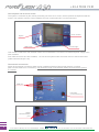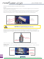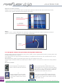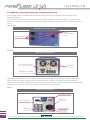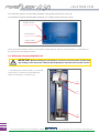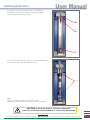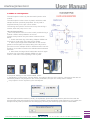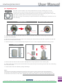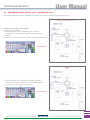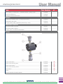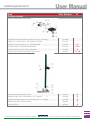
1
- User Manual
ITM - 2012/10/31
Ultra Performance Flash Purification
TM
Crossover flash / prep-LC
Lab Scale
Flash columns up to F800 format
Prep-LC columns up to 80mm id - 15µm
250 ml/min @ up to 50 bar
INTERFINE CHEMICALS
211 bis, avenue JF Kennedy
BP 1140 - 03100 Montluçon
Fax +33 4 70 03 82 60
Hotline +33 4 70 03 73 01 • [email protected]
+33 4 70 03 73 01
Summary
1 > General description
page A. 3
2 > Packing list
page A. 7
3 > Installation
page A. 8
3.1 Assembling the system
3.2 Install the tubing and prepare the containers
3.3 Set up the column, the dry-load, the pre-column & the loop
3.4 Prepare the fractions collection
3.5 Position the stylus
3.6 Make the connections (electrical and data transmission)
3.7 Semi-prep & prep adaptation kit
3.8 Options and accessories
4 > Operation
page A. 24
4.1 Control the system
4.2 Make a liquid injection
4.3 Make a solid injection
5 > Safety regulations
page A. 29
6 > Maintenance
page A. 30
6.1 Introduction
6.2 Removing a pump head
6.3 Replacing a seal
6.4 Cleaning / replacing a check valve
6.5 Replacing the detector deuterium lamp
6.6 Cleaning the detector flow cell
6.7 Cleaning the 6-ways electric valve / replacing the rotor
7 > Preventive measures - Upkeep schedule page A. 38
8 > Warranty
page A. 39
8.1 Generalities
8.2 Limited warranty of consumable parts
9 > List of spare parts + Blow-up views
page A. 42
10 > Specifications page A. 50
► Appendix 1 : Rack sets available page A. 50
► Appendix 2 : Service report page A. 51
2
211 bis, avenue JF Kennedy - BP 1140 - 03100 Montluçon - FRANCE
Tél. +33 4 70 03 88 55 - Fax +33 4 70 03 82 60 - www.interchim.com
[email protected]
1 > General description
The
system is a modern instrument designed for Flash chromatography which allows to
withdraw mobile phases from four containers of solvents, form a gradient, inject liquid or solid samples and
provide the solution to a chromatography column.
A detector measures the absorbance and gives a signal called chromatogram which is visualized with the built-in
computer and the control software “INTERCHIM® Software” installed. Then fractions can be collected with the
fraction collector.
The characteristics of a
are:
Flow rate: Up to 250mL/min
Pressure: Max. 50 bar (725 psi)
Gradient: Quaternary + Air purge
Column size:
From F4 to F1600 format - according to column trademark
Automatic injection valve module: Liquid or solid injection
UV Detection:
Spectrophotometer dual-wavelength (DAD technology, range: 200-600nm)
Collection: Several types of racks available.
The complete system consists of following modules:
The 2-head pump:
As mentioned above, the pump can deliver mobile phase at flow rates up to two hundred and fifty millilitres per
minute with low residual pulsation. It is a high performance double-piston pump (reciprocal movement). Thanks
to a system “pulleys + belt”, a stepper motor drives two special cams on which lean the two pistons. Their motion
generates a cycle and then creates the suction.
A static mixing chamber at the outlet ensures a suitable mixing of solvents whatever the working flow rate, it is
associated with a pressure transducer.
Mixing chamber
Cleaning disc
Leak sensor
Head
Belt
Pressure transducer
Electronic
board
CPU 2010
Motor
Cam
211 bis, avenue JF Kennedy - BP 1140 - 03100 Montluçon - FRANCE
Tél. +33 4 70 03 88 55 - Fax +33 4 70 03 82 60 - www.interchim.com
3
+33 4 70 03 73 01
Moreover, an optic sensor can detect leakages in the pump drain pan. The pumping is then interrupted and the
user informed via the control software.
The 4-ways suction valve allows to perform quaternary elution gradients. A fifth way can be used for Air Purge.
The injection unit and columns holder system:
This device gives the possibility to inject sample automatically (liquid or solid via dry-load) via 6-ways electric
valve directly to the chromatography column installed.
Guidance rail
Pre-column
or dry-load
Column
Knurled Knob
The adjustable height holder of the large black POM holder allows to adapt all types of columns ( from 4g to
1600g) and pre-column (from 4g to 300g). A knurled knob can block this holder on the vertical guidance rail. The
bottom union is fixed.
4
211 bis, avenue JF Kennedy - BP 1140 - 03100 Montluçon - FRANCE
Tél. +33 4 70 03 88 55 - Fax +33 4 70 03 82 60 - www.interchim.com
[email protected]
The UV diode array detector:
This instrument measures the amount of light absorbed by a liquid passing through the cell at a given
wavelength. It is equipped with a deuterium lamp. The two wavelengths available and the SCAN function
are selected within a large range, from 200 to 600nm or from190 to 840nm (in option) - P/N: GO9630.
Deuterium lamp
Flow cell
The fraction collector:
The fraction collector is placed downstream of the detector. After the detection of the signal (chromatogram),
the results obtained at the outlet of the column (peaks) can be directed to tubes disposed on racks. A built-in
3-way valve allows to choose between the collection or the rejection of the liquid.
Tubes
Racks
Motor
Flex
Needle
Electronic board collector
The collector is provided with three stainless steel racks for 18 mm diameter tubes as standard. That represents
in all 176 tubes and a volume of 5.6 Litres.
211 bis, avenue JF Kennedy - BP 1140 - 03100 Montluçon - FRANCE
Tél. +33 4 70 03 88 55 - Fax +33 4 70 03 82 60 - www.interchim.com
5
+33 4 70 03 73 01
The computer and its touch screen:
The system is controlled by the central processing unit via a touch screen, which replaces the keyboard and the
mouse. The operator uses the control software and can create methods to run the instrument.
Touch screen
Stylus
USB Ports
Power light
This module contains the main ON/OFF switch and centralizes the connection for data and power supply to the
other modules.
Four USB connectors are also available, 1 in front of the system under the screen and 3 to the left hand side
(cable maximum length = 2m).
The external connections:
Some others external connectors allow to plug in additional devices like second detector or options
(Réf: HV1200: Multi Com 2 Ports Box). The maximum length of all external cables connected to the system
is 2 metres.
USB port
LAN plug
(Local Area Network)
Serial
communication
port
6
211 bis, avenue JF Kennedy - BP 1140 - 03100 Montluçon - FRANCE
Tél. +33 4 70 03 88 55 - Fax +33 4 70 03 82 60 - www.interchim.com
[email protected]
Optional
“Level sensors” plugs
Analogic
signal inputs
External controls
2 > Packing list
Standard system
Item:
system composed of:
- Pump module,
- Detector module,
- 6-Ways electric valve module, - Fraction collector module,
- Pre-column holder,
- Computer & power supply module.
- Column holder module,
Tubing with fittings (ETFE - OD = 1/8”):
- Suction (1.50m - ID = 2.4mm - x4) ~ with 20cm spring ~
- Gradient valve outlet to Tee Pump inlet (27cm - ID = 2.4mm) ( present on the system)
- Pump outlet to Valve (port n° 4) (46cm - ID = 1.6mm) + Spring = 39cm
- Valve (port n° 3) to Column Holder inlet (60cm - ID = 1.6mm)
- Valve (port n° 5) to Pre-column Holder inlet (38cm - ID = 1.6mm) + Spring = 32cm
- Pre-column Holder outlet to Valve (port n° 2) (56cm - ID = 1.6mm) + Spring = 50cm
- Valve (port n° 6) - Waste outlet (100cm - ID = 1.6mm)
- Valve (port n° 1) - Stainless Steel Adapter for injection
- Column holder outlet to Detector inlet (73cm - ID = 1.6mm)
- Detector outlet to Fraction collector inlet (37cm - ID = 1.6mm)
- Waste outlet (1.50m - ID = 1.6mm)
- Pressure test OQ (PEEK-70cm - 1/16” - ID = 0.5mm)
Rack set “PF4390” for 18mm diameter tubes (4 racks)
Semi-prep and prep adaptation kit (P/N: GO2400)
PEEK union 10-32 female (P/N: NR0860)
Solvent Tray with a drainage system
- Serial communication cables (3 x Sub-D9 male/female - 1 x Sub-D9 female/female)
- Distribution power cables (3 x main voltage supply - 1 x 24V)
Fittings for cleaning discs connections (2 long nuts + 2 ferrules)
Binding column
General power cable (model according to the destination country)
USB key (including the file of installation ‘.exe’ of the freeware ‘Interchim® Software Demo)
Stylus & Keyboard
Columns starting kit (2x PF-15SIHP/25G, 2x PF-30SIHP/25G, 2x PF-50SIHP/25G)
Documentation:
system
- User Manual for
- Instruction Manual for “Interchim® Software”
- “Adjusting Protocol of Assembled Unit” for “Flash 06 DAD” UV detector
- PDF document : Operational Qualification and test report (“My documents”)
- Quick start for “Interchim® Software”
- Installation Qualification (x2)
211 bis, avenue JF Kennedy - BP 1140 - 03100 Montluçon - FRANCE
Tél. +33 4 70 03 88 55 - Fax +33 4 70 03 82 60 - www.interchim.com
7
+33 4 70 03 73 01
3 > Installation
3.1 Assembling the system
Select a suitable location by ensuring adequate air-space (~15cm around the system) to provide ventilation of
the controller, the pump, the detector cooling fans. Its total weight is approximately 66kg.
Air extractions
Assemble the system in the following order:
- Fraction collector: ~ 25kg
- 6-Ways Electric Valve: 5kg
- Unit control: ~ 15kg
- Detector: ~ 7kg
- Pump: ~ 8kg
- Pre-column Holder: 2kg
- Column Holder: ~ 3kg
- Solvent tray: ~ 1kg
Put then the stainless steel solvent tray supplied on top to dispose solvents (up to five).
They cover the totality of the system with a drainage system and their design avoids any leakage risk.
8
211 bis, avenue JF Kennedy - BP 1140 - 03100 Montluçon - FRANCE
Tél. +33 4 70 03 88 55 - Fax +33 4 70 03 82 60 - www.interchim.com
[email protected]
Fix the column holder and pre-column holder as below:
Column holder
- Insert the column holder at the bottom
of the collector.
- Put the binding column and the screw
on the middle of the column holder.
Pre-column holder
- Insert the pre-column holder
at the bottom of the collector.
- Put the screw at the top
of the pre-column holder.
3.2 Install the tubing and prepare the containers
The tubes situated outside the housing are delivered apart in order to avoid all deterioration during transfer, they
are already equipped with the suitable fittings (nut + ferrule) to connect them easily to the system. Regarding the
main circuit, two sizes of tube are used:
1/8” - ID = 2.4mm for suction
1/8” - ID = 1.6mm for others.
211 bis, avenue JF Kennedy - BP 1140 - 03100 Montluçon - FRANCE
Tél. +33 4 70 03 88 55 - Fax +33 4 70 03 82 60 - www.interchim.com
9
+33 4 70 03 73 01
Follow the instructions below to correctly install the tubing:
Suction:
Provide yourself with the four “Suction tubes” (l=1.5m, 1/8” - ID=2.4mm) supplied, they are more brittle than
others so take care not to bend them.
For the tube “A”, take the extremity where there is a fitting with a long spring and put the ferrule in the PEEK
body of the suction valve. Screw the PEEK nut, tighten it hand-tight and position properly the long spring.
Renew the same operation for “B”, “C” and “D” as indicated on the photo. The “Air” inlet stays free.
Outlet
Gradient
valve body
PEEK nut
Spring
CAUTION: Don’t put the ETFE plug in the valve “air”.
To ensure the pumping continuity of the solvents and avoid the air entry in the hydraulic circuit, the others
extremities can be equipped with ballasts (in option, P/N: DZ7360). It consists in fact to put a fitting (nut + set
ferrule) and screw it in a stainless steel piece which serve of weight to maintain the tubes at the bottom of the
containers.
PEEK nut
Ballast
Position the solvents containers on the solvent tray for instance, and put the ballasted tubes into them.
Gradient valve:
The gradient valve to Tee Pump inlet tube is already connected into the pump (l= 27cm - 1/8” ID= 2.4mm) as
shown below :
Tee
pump inlet
Pump outlet
Gradient
valve outlet
10
211 bis, avenue JF Kennedy - BP 1140 - 03100 Montluçon - FRANCE
Tél. +33 4 70 03 88 55 - Fax +33 4 70 03 82 60 - www.interchim.com
[email protected]
6-Ways electric valve fluidic connection:
The fluidic connection on the 6-ways electric valve module is explained below:
Pump to valve (port n°4):
Using the 46cm x 1.6mm ID tube insert one end into the pump outlet and the other end into the valve n°4 of the
6-ways electric valve. Position the tubing as shown below and tighten each fitting:
Pump outlet
Valve (port n°4)
211 bis, avenue JF Kennedy - BP 1140 - 03100 Montluçon - FRANCE
Tél. +33 4 70 03 88 55 - Fax +33 4 70 03 82 60 - www.interchim.com
11
+33 4 70 03 73 01
Valve (port n°3) to column holder:
Using the 60cm x 1.6mm ID tube insert one end into
the valve n°3 of the 6-ways electric valve and the other
end into the column holder intlet. Position the tubing as
shown below and tighten each fitting:
Valve
(port n°3)
Column
holder inlet
Valve (port n°5) to pre-column holder:
Using the 38cm x 1.6mm ID tube insert one end into
the valve n°5 of the 6-ways electric valve and the
other end into the pre-column holder inlet. Position the
tubing as shown below and tighten each fitting:
Valve
(port n°5)
Pre-column
holder inlet
Pre-column holder to valve (port n°2):
Using the 56cm x 1.6mm ID tube insert one end into
the Pre-column holder outlet and the other end into
the valve n°2 of the 6-ways electric valve. Position the
tubing as shown below and tighten each fitting:
Valve
(port n°2)
Pre-column
holder outlet
12
211 bis, avenue JF Kennedy - BP 1140 - 03100 Montluçon - FRANCE
Tél. +33 4 70 03 88 55 - Fax +33 4 70 03 82 60 - www.interchim.com
[email protected]
Valve (port n°1):
Screw the Stainless Steel adapter for injection into the
port n°1 of the 6-ways electric valve and tighten:
Adapter stainless
steel for injection
Valve (port n°6):
Using the 1m x 1.6mm tube attach the end with
the fitting into the valve n°6 of the 6-ways electric
valve and tighten. On the other end, insert into an
appropriate waste bottle.
Waste tube:
valve (port n°6)
Column holder to detector:
Using the 73cm x 1.6mm ID tube insert one end
into the column holder outlet of the stainless steel
bulkhead union 90° and the other end into the detector
inlet. Position the tubing as shown below and tighten
each fitting:
Detector inlet
Column holder
outlet
211 bis, avenue JF Kennedy - BP 1140 - 03100 Montluçon - FRANCE
Tél. +33 4 70 03 88 55 - Fax +33 4 70 03 82 60 - www.interchim.com
13
+33 4 70 03 73 01
Detector to fraction collector:
Using the 37cm x 1.6mm ID tube insert one end into the detector outlet and the other end into the fraction
collector inlet. Seat the ferrules and hand tighten each fitting:
Detector outlet
Fraction
collector inlet
Waste:
Using the 1.5m x 1.6mm tube attach the end with the fitting into the fraction collector waste port and hand
tighten. On the other end, insert into an appropriate waste bottle.
Waste
3.3 Set up the column, the pre-column, the dry-load and the loop
A large range of columns can be used on the column holder, columns packed with normal or reverse phase, with
an external diameter up to 120mm.
The “Extension kit for Large columns (P/N: DU9671)” is supplied with this device, this overall dimension can go
up to 120mm.
On the pre-column holder, dry-load and pre-column (4g up to 300g) can be used.
A large range of stainless Steel loop injection(from 100µL to 100mL or more) can be used on the 6-ways electric
valve.
Set up the column:
14
-1Unscrew lightly the knurled knob in
order to allow its vertical movement.
-3Move up the large black POM holder on the
vertical guidance rail and place the bottom fitting
of the column on the “Adapter ETFE or Stainless
steel Luer lock female to ¼-28 male” located on
the stainless steel bulkhead union 90°.
-2Unlock the black ring of the fitting
“Adapter PEEK Luer lock male to
¼-28 male” located on the column
holder.
-4Move down the large black POM holder and
lock again the black ring of the fitting “Adapter
PEEK Luer lock male to ¼-28 male” to the top
fitting of the column.
211 bis, avenue JF Kennedy - BP 1140 - 03100 Montluçon - FRANCE
Tél. +33 4 70 03 88 55 - Fax +33 4 70 03 82 60 - www.interchim.com
[email protected]
Set up the dry-load and pre-column:
To inject solid sample, make dry loading injection, or use the pre-column, you have the possibility to use a
column of which the maximum dimensions are 27cm in height and 70mm for external diameter. Install it as
follows:
-1Unscrew lightly the knurled knob
of the holder in order to allow its
vertical movement.
-2Unlock the black ring of the fitting
“Adapter PEEK Luer lock male
to ¼-28 male” of the pre-column
holder.
-3Move up the large black POM holder on the
vertical guidance rail and place the bottom fitting
of the dry-load or pre-column on the “Adapter
ETFE or Stainless steel Luer lock female to ¼-28
male” located on the stainless steel bulkhead
union 90°.
-4Move down the large black POM holder and
lock again the blazzack ring of the fitting
“Adapter PEEK Luer lock male to ¼-28 male” to
the top fitting of the dry-load.
Set up the loop:
Connect the loop into the 6-ways electric valve
between the port n°2 and n°5 as shown below and
thighten with wrench ¼”-5/16”:
211 bis, avenue JF Kennedy - BP 1140 - 03100 Montluçon - FRANCE
Tél. +33 4 70 03 88 55 - Fax +33 4 70 03 82 60 - www.interchim.com
15
+33 4 70 03 73 01
3.4 Prepare the fractions collection
According to the type of collection required (small or big volumes, short or long fractionation, etc…), the
equipments to install are different.
The standard rack set (18x150mm) supplied is “PF4390”, composed of four racks for 176 tubes in all, it allows a
total collection volume of 5.6 Litres with 180 mm high tubes.
CAUTION: Before any action, take a diagonal plier and carefully cut the cable tie
which holds the arm during the transfer.
Dispense arm
Cable Tie
Place first the tubes in the holes and put then the racks on the tray. Thanks to notches machined on racks and
positioning guides already mounted on the system, their emplacement is easy and necessarily proper.
Positioning notch
Back guides
Well-placed rack
Front guides
You can also equip your collector with an optional Enhancement tube device for 13x100m (P/N: DW3360). It is
designed for elevating the racks with small height tubes. Its installation is simple too because you have just to
emplace it on the collector tray using positioning guides.
Several models of rack set are available, find a detailed list on “APPENDIX 1”.
16
211 bis, avenue JF Kennedy - BP 1140 - 03100 Montluçon - FRANCE
Tél. +33 4 70 03 88 55 - Fax +33 4 70 03 82 60 - www.interchim.com
[email protected]
It is important to maintain appropriate spacing of the dispensing needle above the tubes. A space of 5-25mm
between the end of the needle to the top of the tube is recommended.
To adjust the needle height turn off the system, remove the racks and gently move the arm into an easy to
access position. Do not use the needle to relocate the arm as bending and mis-alignment may occur. Loosen the
set screw and adjust the height of the needle and then tighten the set screw. When the system is turned on the
arm will return to its «home» position.
Collection tubing
Dispense arm
Dispense head
Needle
Tightening screw
3.5 Position the stylus
The stylus is supplied to control the system via computer touch screen. A fixed holder allows to easily put away it
when it is not used and its extensible cord (linked to the holder) gives the suitable length.
Stick the stylus holder just as you like in order to profit at best of
its features (i.e. to the left side of the system as showed on this
picture).
211 bis, avenue JF Kennedy - BP 1140 - 03100 Montluçon - FRANCE
Tél. +33 4 70 03 88 55 - Fax +33 4 70 03 82 60 - www.interchim.com
17
+33 4 70 03 73 01
3.6 Make the connections (electrical and data transmission)
The complete system is supplied with appropriate fuses and is ready to operate at the line voltage of the
shipping destination.
The Computer module serves as the primary point for power distribution and data collection. The ports on the
modules are labelled to ensure proper connections. Using the cables provided connect each module to the unit
control.
Unit control:
Back panel of the unit control
Serial
communication
ports
Power sockets
Detector:
Back panel of the detector
24 V round connector
Axial fans
Serial port (> COM2)
Take first the special cable for 24 V supply and screw the round male connector in the suitable socket (label
“DET.”) of the unit control. Screw the other end (round female connector) in the back panel of the detector.
Link the unit control (label “COM2: DETECTOR”) and the detector module using the Sub-D9 female/female cable
supplied. Do not forget to set the connectors by fastening the two fixing screws.
Pump:
Back panel of the pump
Serial port (>COM1)
8-pin connector
Axial fan
Switch 0/1
Fuses drawer
Power plug
18
211 bis, avenue JF Kennedy - BP 1140 - 03100 Montluçon - FRANCE
Tél. +33 4 70 03 88 55 - Fax +33 4 70 03 82 60 - www.interchim.com
[email protected]
Take the power cable for main voltage supply and connect it at the same time in the plugs of the unit control
(label “PUMP”) and in the sockets of the pump module.
Link the unit control (label “COM1: PUMP”) and the pump module using the Sub-D9 male/female cable supplied.
Do not forget to set the connectors by fastening the two fixing screws.
Back panel of the fraction collector
External controls
Switch 0/1
Serial port
(> COM3)
Fuses drawer
Analogic
inputs (-/+)
for second
detector
acquisition
Power plug
Take the power cable for main voltage supply and connect it at the same time in the plugs of the unit control
(label “COLL.”) and in the sockets of the pump module.
Link the unit control (label “COM3: COLLECTOR”) and the collector module using the Sub-D9 male/female cable
supplied. Do not forget to set the connectors by fastening the two fixing screws.
6-ways electric valve module :
Back panel of the 6-ways electric valve
Take the power cable for main voltage supply and connect it at the same time in the plugs of the unit control and
in the sockets of the pump module.
Link the unit control (“COM4”) and the pump module using the Sub-D9 male/female cable supplied. Do not forget
to set the connectors by fastening the two fixing screws.
Plug the AC power cable supplied in the general switch located to the left side of the system, and after to the
mains, knowing that the connector depends also on the destination country (comply with country regulations in
effect).
211 bis, avenue JF Kennedy - BP 1140 - 03100 Montluçon - FRANCE
Tél. +33 4 70 03 88 55 - Fax +33 4 70 03 82 60 - www.interchim.com
19
+33 4 70 03 73 01
For American system: 110-120 VAC; 50-60 Hz; 6.2 A (delay action fuses 2 x 6.3 A)
For European system: 220-240 VAC; 50-60 Hz; 3.1 A (delay action fuses 2 x 3.15 A)
ON/OFF Switch
Fuses Drawer
Power Cable
Check that all the ON/OFF switches of secondary modules (pump, detector, collector) are on “I” and switch on
the unit with the main ON/OFF switch.
3.7 Semi-prep and prep adaptation kit
IMPORTANT: Before installing the semi-prep kit, you must clean the system and the loop
(by clicking on the loop in the software) with Isopropanol, then with the less polar solvent.
1. Unscrew peek ¼-28 Long Nut (1), Luer male
(with lock) to 1/4-28 male (2) and Stainless
Steel Luer female to 1/4-28 male (3)
(1)
(2)
(3)
20
211 bis, avenue JF Kennedy - BP 1140 - 03100 Montluçon - FRANCE
Tél. +33 4 70 03 88 55 - Fax +33 4 70 03 82 60 - www.interchim.com
[email protected]
2. Replace by semi-prep adapter inlet (1) ( Screw the
inlet adapter on half of the thread) & oulet (2) column,
and screw peek ¼-28 Long Nut (3),
(3)
(1)
(2)
3. Put the semi-prep column: push the Stainless Steel tubing
in the column and screw the PEEK fitting (1)
(1)
Note:
There is a specific adapter for the prep column.
Operation is the same than for the prep column connection.
CAUTION: To purge the system in semi-prep configuration,
remove the column and install the PEEK union 10-32 female (P/N: NR0860)
211 bis, avenue JF Kennedy - BP 1140 - 03100 Montluçon - FRANCE
Tél. +33 4 70 03 88 55 - Fax +33 4 70 03 82 60 - www.interchim.com
21
+33 4 70 03 73 01
3.8 Options and accessories
1. “Solvents level sensors 5-1 (Global)” (P/N: FSP720) or “Solvents level sensors 5-5 (Separated)” (P/N: FSP730)
2. “Bar code reader” (P/N: GO2380)
3. “Enhancement tube device for 13 x 100mm tubes” (P/N: DW3360)
4. “Video camera + TLC plates holder” (P/N: GO2390)
5. “Fume enclosure” (P/N: PF4350)
6. “Quad system” (P/N: PF4360)
7. “2nd acquisition channel” (P/N: PF4320)
8. “FLASH- ELSD” (P/N: FI0320)
9. “Funnel rack set 1 unit” (P/N : FJ4331) or “Funnel rack set 4 units” (P/N: FJ4330)
10. “ Safety solvent caps kit” (4 units) (P/N: DV2760)
11. “Safety waste cap (with container 5L + filter” (P/N: IO6930)) or “Safety waste cap (with container 20L + filter”
(P/N: JO4500))
12. “Drainage system of the tray collector” (P/N: DZ7790)
13. “2 columns selection (switching valve)” (P/N: LO6600)
14. “Backflush valve” (P/N: LO6610)
15. “2 columns selection (switching valve) + Backflush valve” (P/N: LO6620)
16. “2nd fraction collector coupled” (P/N: JV0950)
17. “RI IOTA 2” (P/N: FSQ600)
18. “Mass Spectrometer + interface” (P/N: JO1090)
19. “CarouXel” (P/N: JO3750)
20. “Autosampler” (P/N: LO8850)
21. “Ballasting kit” (P/N: DZ7360)
22. “Stainless steel loops”
23. “Racks set”
Designation / Items:
1. Solvent level sensors 5-1 (global)
- Communication interface 5-1 + cable
- Sensors + cables (x 5)
- Straps (80cm) (x 5)
- Removable cable ties (x 5)
- Power adapter
- Hardware
- Installation procedure
1. Solvent level sensors 5-5 (separated)
- Communication interface 5-5 + cable
- Sensors + cables (x 5)
- Straps (80cm) (x 5)
- Removable cable ties (x 5)
- Power adapter
- Hardware
- Installation procedure
2. Bar code reader
- Reader with USB connection
- Bracket
- Hardware
- Installation procedure
22
211 bis, avenue JF Kennedy - BP 1140 - 03100 Montluçon - FRANCE
3. Enhancement tube device for 13x100mm tubes
4. Video camera + TLC plates holder
- Webcam (with USB connection)
- Bracket
- CD for Webcam drivers installation
- TLC plates holder
- Hardware
- Installation procedure
5. Fume enclosure
- Side panel
- Transparent door
- 5 screws
- Collar
- Magnetic flap
- Hardware
- Installation procedure
6. Quad system
- Module for 4 additional columns installation
- Inlet tubing with stainless steel fitting set
(1/8” - ID = 1.6 mm - 1.50m)
Tél. +33 4 70 03 88 55 - Fax +33 4 70 03 82 60 - www.interchim.com
[email protected]
- Outlet tubing (1/8” - ID = 1.6 mm - 1.50m)
- PEEK ¼-28 long nut for 1/8” tubing (x3)
- ETFE ferrule for 1/8” tubing (x 3)
- CD for TRP converter drivers installation
- External control cable
- USB cable
- Power cable
(model according to the destination country)
- Hardware
- Installation procedure
7. 2 Acquisition channel
- Module USB-1408FS + USB cable
- USB key for drivers installation
nd
8. FLASH-ELSD
- FLASH-ELSD
- 1V Output cable
- Power cable
- Splitter box with micro-needle (option)
- ETFE Tubing (1/16’’, ID= 0.25mm) ;
Splitter Outlet - ELSD Inlet : length = 30cm,
fitting 10-32 Male (P/N: 780771)
(connected to Splitter box)
- ETFE Tubing (1/8’’, ID= 1.6mm);
Splitter Outlet - UV Inlet : length = 72cm
+ Adapter ¼-28F à 10-32M (P/N: 737664)
+ spring 20cm (P/N: PFS800) (connected
to Splitter box)
- ETFE Tubing (1/8’’, ID= 1.6mm) ;
Column Outlet - Splitter Inlet: length = 72cm +
Adapter ¼-28F à 10-32M (P/N: 737664)
(connected to Splitter box)
- Manometer (P/N: FJ6720) (option)
- 2 red or white tubing to connect the gas
( 6mm OD, 2 meter + 1 meter and fitting)
- 1 PEEK fitting 10-32 Male, fitting Inlet ELSD
(P/N: 780771)
- Adapter 1/4’’-28Female - 1/4’’-28 Female Nylon
(P/N:187210) (only for the puriFlash® SPOT II
- Union PEEK 10-32M-1/4-28F (P/N: 737664)
+ Internal reducer 1/16’’-1/8’’ (P/N: 229980)
(only for semi-prep and prep configuration on
puriFlash® 4100, puriFlash® 4250-250,
puriFlash® 4250-40),
- Installation procedure
9. Funnel rack set 1 unit or Funnel rack set 4 units
10. Safety solvent caps kit (4 units)
11. Safety waste cap (with container 5L + filter)
or Safety waste cap (with container 20L + filter)
12. Drainage System of the tray collector
- Backflush valve
- ETFE tubing
- Installation procedure
15. 2 columns selection (switching valve)
+ Backflush valve
- 2 valves
- ETFE tubing
- Installation procedure
16. 2nd fraction collector coupled
- Fraction collector
- General power cable
- Serial communication cable (Sub-09 male/female)
- Tubing with 2 fitings and 2 ferrules
(l = 3m - 1/8’’ - ID = 1.6mm)
17. RI IOTA 2
- 1V Output cable
- Power cable
- ETFE Tubing (1/16’’ - ID = 1mm); RI outlet (fitting
10-32 Male; P/N: 780770) - UV inlet (fitting and
ferrule for 1/16’’ tubing; P/N: 167155 and AB8790);
length = 70cm
- Adapter 1/4’’-28 Female - 1/4V-28 Female Nylon
(P/N: 187210) (only for the puriFlash® SPOT II)
- User's Manuel
- Installation procedure
18. Mass spectrometer + interface
19. CarouXel
- Power cable
- RS 232 cable
- Installation procedure
20. Autosampler
- Power cable
- RS 232 cable
- User's manuel
- Installation procedure
21. Ballasting kit for 1/8'' tubing (5 units)
22. Stainless steel loops
9 different loops (100µL, 250µL, 500µL, 1mL, 2mL,
5mL, 10mL, 20mL, 40mL)
23. Racks set
13x100mm (P/N: PF4370), 16x150mm (P/N: PF4380),
18x150mm (P/N: PF4390), 21x150mm (P/N: PF4410),
25x150mm (P/N: PF4420), 28x180mm (P/N: PF4430),
29.5x200mm (P/N: PF4440)
Plateform rack for bottles (P/N: LV5200)
13. 2 columns selection (switching valve)
- Switching valve
- ETFE tubing
- Installation procedure
14. Backflush valve
211 bis, avenue JF Kennedy - BP 1140 - 03100 Montluçon - FRANCE
Tél. +33 4 70 03 88 55 - Fax +33 4 70 03 82 60 - www.interchim.com
23
+33 4 70 03 73 01
4 > Operation
4.1 Control the system
. After few seconds and
When all the installations and connections are made, switch on the
the initialisations of different instruments, the control software “Interchim® Software” automatically starts. Note
the good starting (no message “Communication Error”), is necessary for the correct working of the system.
Once the user interface opened, several graphic elements allow to see in real time the state of the instruments
and the evolution of the working parameters. The application has been developped with the aim of being
convivial and intuitive. Refer to the “Instruction Manual” supplied for more explanations on the software use.
Use the stylus on the tactile screen to create methods in the software and control the system.
24
211 bis, avenue JF Kennedy - BP 1140 - 03100 Montluçon - FRANCE
Tél. +33 4 70 03 88 55 - Fax +33 4 70 03 82 60 - www.interchim.com
[email protected]
4.2 Make a liquid injection
The liquid injection is done by the automatic injection valve
module with the loop, the volume is predefined (from 100µL
to 40mL or more).
The loading and injection can be done at any time during a
method, when the pump runs or not.
Here is the procedure:
The 6-way electric valve is on the “LOAD” position during a
method creation and column equilibration.
Fill a syringe with the volume of sample chosen and place
it in the “Adapter Stainless steel for injection” (port n° 1). Keep
the syringe on this adapter to avoid the leak of the sample.
Fill the loop with the content of the syringe. If the quantity injected is greater than the capacity of the loop,
the surplus flows in the “waste” tube (port n° 6).
In the panel “Settings” of the edited method, select :
“Equilibration” in the section “Injection Mode”. According to the type of the column, a time and a flow rate are
selected by default. They depend on the column parameters, but you can modifiy them if needed.
“Loop injection” for the injection by the loop.
211 bis, avenue JF Kennedy - BP 1140 - 03100 Montluçon - FRANCE
Tél. +33 4 70 03 88 55 - Fax +33 4 70 03 82 60 - www.interchim.com
25
+33 4 70 03 73 01
After having launched the method (= “RUN”), the equilibration phase starts. That allows to pack the column with
the solvents used. At the end of the time (or at a click on “START”), the 6-ways electric valve switches on “run”
position, the sample is pushed in the chromatography column by the solvents pumped and the method starts.
26
211 bis, avenue JF Kennedy - BP 1140 - 03100 Montluçon - FRANCE
Tél. +33 4 70 03 88 55 - Fax +33 4 70 03 82 60 - www.interchim.com
[email protected]
4.3 Make a solid injection
The solid injection is done by the automatic injection valve
module.
The solid injection is done via a dry-load in which the solid
sample has been previously deposited. The dry-load is
emplaced directly on the pre-column holder.
The loading and injection can be done at any time during a
method, when the pump runs or not.
Here is the procedure :
The 6-way electric valve is on the “LOAD” position during a
method creation and equilibration of column.
Place the dry-load on the pre-column holder as shown
below:
1. Unlock the black ring of the fitting “Adapter PEEK Luer
lock male to ¼-28 male” of the pre-column holder.
2. Move up the large black POM holder on the vertical
guidance rail and place the bottom fitting of the dry-load or
pre-column on the “Adapter ETFE or Stainless steel Luer lock
female to ¼-28 male” located on the stainless steel bulkhead
union 90°.
3. Move down the large black POM holder and lock again
the black ring of the fitting “Adapter PEEK Luer lock
male to ¼-28 male” to the top fitting of the dry-load.
1.
2.
3.
In the panel “Settings” of the method edited, select:
“Equilibration” in the section “Injection Mode”. According to the type of the column, a time and a flow rate are
selected by default. They depend on the column parameters, but you can modifiy them if needed.
“Loop injection” for the injection by the solid deposit.
After having launched the method (= “RUN”), the equilibration phase starts. That allows to pack the column with the
solvents used. At the end of the time (or at a click on “START”), the 6-ways electric valve switches on “run” position, the
sample in the dry-load is pushed in the chromatography column by the solvents pumped and the method starts.
211 bis, avenue JF Kennedy - BP 1140 - 03100 Montluçon - FRANCE
Tél. +33 4 70 03 88 55 - Fax +33 4 70 03 82 60 - www.interchim.com
27
+33 4 70 03 73 01
28
211 bis, avenue JF Kennedy - BP 1140 - 03100 Montluçon - FRANCE
Tél. +33 4 70 03 88 55 - Fax +33 4 70 03 82 60 - www.interchim.com
[email protected]
5 > Safety regulations
This equipment is built according to the E.U. security standards. However, risks and dangers could remain if the
system is used in a different way from which it is intended or if it is used by untrained personnel.
should only be used by laboratory trained or experienced persons. The user should
The
inform the distributor in case of problems and safety-related matters that occur during the use of the instrument.
WARNING
Alerts you to potential hazardous situations that could
result in serious injury or damage of the system.
This system is designed for chromatographic purposes. It must be operated using appropriate solvents and
within specified ranges for pressure, flows and temperatures as described in this manual. If it is used in a
manner not specified by the manufacturer, the protection provided by the equipment may be impaired.
When handling potentially hazardous solvents and samples, it is important to follow standard laboratory safety
procedures. Common chemicals used in the laboratory can be toxic, corrosive, flammable or a combination of
these properties.
A list of all safety aspects is outside the scope of this manual but the following points should be
considered:
Ensure adequate ventilation,
Wear eye protection,
Wear gloves when handling chemicals,
Ensure all liquid containers are secure,
No smocking or naked flames,
Clean-up all spillages…
WARNING:
EYE HAZARD
Eye damage could occur from particles or chemicals.
Use proper eye protection.
If a line ruptures or a valve opens accidentally under pressure, a potentially hazardous spray of liquid might
be generated by the pump. Never open a solvent line or valve under pressure. Stop the pump first and let the
pressure drops to zero. Wear protection glasses.
WARNING:
SHOCK HAZARD
211 bis, avenue JF Kennedy - BP 1140 - 03100 Montluçon - FRANCE
Hazardous voltages are present inside the
instrument. Disconnect from main power before
removing screw-attached panels.
Tél. +33 4 70 03 88 55 - Fax +33 4 70 03 82 60 - www.interchim.com
29
+33 4 70 03 73 01
Removal of protective panels may only be performed by an authorized person. When it is necessary to use
a non-original power cord plug, make sure the replacement cord adheres to the color-coding and polarity
described in the manual and local building safety codes. Replace blown fuses with fuses of the size and rating
stipulated in the manual. Replace faulty or frayed power cords immediately with the same type and rating. Make
sure that voltage sources and line voltage match the value for which the instrument is wired.
To ensure your own safety, thus of your co-workers, and safe operation of the equipment, observe the
following instructions:
Use a 3-wire mains socket with ground connection, grounding is necessary to ensure operator safety and
proper operation.
Take care of inflammable solvents.
Store the system after having passed a clean solvent in the hydraulic circuit when not in use. Do not leave
buffer in the system, it may cause blockages and damage the seals on start-up.
Before moving the instrument, the external connections have to be disconnected, the hydraulic circuit rinsed
and the inlets/outlets corked. The instrument must be carefully carried in its original box.
6 > Maintenance
6.1 Introduction
This chapter describes actions that should be performed on a routine basis to ensure long term safe and trouble
free operation of the system. The frequency of the maintenance activities is dependent on the nature of the
application (the solvents used, the quantity of the mobile phase delivered by the pump, the level of cleanliness
of the facility, etc...). The pump has been designed for reliability and needs very little routine maintenance when
operated correctly.
The following figure represents the liquid connections of the pump:
Reduced accuracy of the pump may be due to seal wear or to a fault in the check valves. This section provides
information and procedures about how to replace consumable parts and how to maintain the instrument.
The removal of protective panels may only be performed by an authorized person.
6.2 Removing a pump head
When disassembling or reassembling the pump, make sure that each component is clean and take care that the
system is assembled in a clean environment.
Remove it if you need to replace its seal (details hereafter).
1. Purge the pump head with a suitable solvent or alcohol (1-propanol or 2-propanol).
2. Switch off the module and disconnect it from the electrical supply.
3. Remove the plastic cover to gain access to the pump heads.
4. Disconnect the Suction and Delivery tubing and fittings.
5. Remove the two screws (Allen wrench 3mm). Carefully unscrew, alternating from one to the other.
6. Carefully remove the pump head. The piston and the seal are now visible.
30
211 bis, avenue JF Kennedy - BP 1140 - 03100 Montluçon - FRANCE
Tél. +33 4 70 03 88 55 - Fax +33 4 70 03 82 60 - www.interchim.com
[email protected]
6.3 Replacing a seal
Piston seal
There are in all four seals, one of every head and one of every cleaning disc. You can
exchange them by removing the pump heads and cleaning disc as explained previously.
1. Remove the seal using a small screwdriver. Be sure to avoid scoring any part of the pump
head and the cleaning disc as a scratch will prevent proper sealing.
If the seat is scored, it is necessary to replace the head or the cleaning disc and these are not
under warranty.
Head (back views)
Cleaning disc (back views)
Seal
Seal seat
Seal
2. Thoroughly clean the seal seat with alcohol to remove possible seal particles and plunge the new seal in
propanol-2 for lubrication.
3. Place the new seal into the pump head or the cleaning disc and provide yourself with a special tool sold with
the first set of seals (P/N: PFS040).
4. Position the part “A” on the head and slip the part “B” into “A”. Then, hit gently with the fist on the part “B”.
Tool (2 Parts)
A
B
Seal
5. Remove the tool and note that the seal is well-placed in the pump head or in the cleaning disc.
6. Finally replace the cleaning disc and the head on the piston and put its two fixing screws with care, alternating
from one to the other.
7. Connect the Suction and Delivery tubing and fittings.
Note :
The life time of the seals is dependent on the flow rate, pressure, type of liquids used and temperature
but mostly on the cleanliness of the mobile phase and sample. The presence of micro-particles will cause
accelerated wear and tear of the seals. Similarly any dried buffer particles on the piston will damage the seal.
211 bis, avenue JF Kennedy - BP 1140 - 03100 Montluçon - FRANCE
Tél. +33 4 70 03 88 55 - Fax +33 4 70 03 82 60 - www.interchim.com
31
+33 4 70 03 73 01
6.4 Cleaning / replacing a check valve
Check valve
Abnormal pressure fluctuation or the observation of pump noise on the data system
is usually due to check valve problems. The noise is regular in nature and is due to
pressure and flow variation. Pump accuracy is also compromised. Details on check valve
repairs are given below.
There are four check valves, two per head, one for each inlet (model 10mm,
P/N: PFS930) and one four each outlet (model 8mm, P/N: PFS920). If they become dirty,
they will not open and close correctly for a long time.
1. Purge the pump head with a suitable solvent or alcohol (1-propanol or 2-propanol).
2. Switch off the module and disconnect it from the electrical supply.
3. Remove the plastic cover to gain access to the pump heads.
4. Disconnect the Suction and Delivery tubing and fittings.
5. Unscrew the check valve housing using a spanner 17mm.
6. Clean the check valves or provide yourself with news.
The cleaning allows to remove the particles present in the valves by placing
them in an ultrasonic bath with methanol or acetone during approximately
five minutes.
Ensure that the arrow is directed downwards during the cleaning. Else
damage to the surface quality or the ball and the seat will occur.
7. Replace the check valves. Whether it is for the inlet (10 mm) or the outlet
(8mm), make sure the arrow is always directed upwards.
Inlet (Suction)
Outlet (Delivery)
Check valve housing
Check valve
(Ø 8 mm)
Check valve
(Ø 10 mm)
8. Hard-tighten the valve housing in the head until hearing a little crunch which means that the new check valve
is enough tight and the imperviousness properly done. This noise corresponds to the collapsing of the top and
bottom membranes.
9. Connect the Suction and Delivery tubing and fittings.
32
211 bis, avenue JF Kennedy - BP 1140 - 03100 Montluçon - FRANCE
Tél. +33 4 70 03 88 55 - Fax +33 4 70 03 82 60 - www.interchim.com
[email protected]
6.5 Replacing the detector deuterium lamp
Deuterium lamp
1. Purge the system with a suitable solvent, with then alcohol, and with air.
2. Switch off the system and disconnect it from the electrical supply. It will be
reconnected only when the panel will be installed back in its place.
3. Let the lamp cools down fifteen minutes after switching it off.
4. Remove tubing and connections from the detector module and remove it from the
whole system (you must first remove the pump module).
5. Position the detector module on its side in order to view the bottom and unscrew the
three M3 cylindrical-head screws indicated below using an Allen wrench (2.5mm). Take
care not to lose M4 flat washers.
6. Put the detector in the upright position and take off the front plastic cover.
7. Then unscrew the two M4 domed-head screws located on the back of the module using an Allen wrench
(3mm) and take off the top sheet cover.
8. Loosen the screw on the socket of light tube behind the cell compartment using T-20 Torx adapter. Turn the
lamp socket to the horizontal position and tighten the same screw to fix it again.
9. Take the lamp power supply cables and disconnect the 3-pin white connector. Loosen and remove the two
screws which hold the lamp using T-10 Torx adapter.
211 bis, avenue JF Kennedy - BP 1140 - 03100 Montluçon - FRANCE
Tél. +33 4 70 03 88 55 - Fax +33 4 70 03 82 60 - www.interchim.com
33
+33 4 70 03 73 01
10. Remove the lamp from the lamp socket and provide yourself with a new one.
Never touch quartz bulb of the lamp with bare fingers to avoid damages causing faulty
working of the detector.
11. Carefully insert the new lamp assuring that it is correctly positioned.
Should you touch the glass of the lamp accidentally, clean it thoroughly with a lint free cloth and alcohol.
12. Screw it in securely and connect the plug in the 3-pin white socket.
13. Reassemble the unit by making the same steps but in the reverse order.
After the lamp replacement, recalibration and zeroing of the counter of operating hours must be carried out
(cf. Service Info#39).
6.6 Cleaning the detector flow cell
Flow cell
A “contaminated” cell in lowered light transmission may increase noise level and make
difficulties at zeroing. The simplest cleaning method is flushing dismantled cell with
suitable solvents. The cell must be taken out from the instrument before washing.
1. Follow the instructions 1 to 7 described in the previous chapter "6.5 Replacing
detector deuterium lamp" in order to properly disassemble the system.
2. Disconnect the outlet tubing from the cell (PEEK nuts).
3. Remove easily the cell from the system by tilting the locking lever, placing one hand
under the cell to prevent it from falling to the bottom and tilting the locking lever with the
other hand.
4. Select the solvent type according to character of contamination by a series of
mutually miscible solvents. It is possible to use both organic and inorganic solvents and
diluted solutions of acids.
5 - Flush the cell with pure solvent and rinse
extensively.
6 - Reassemble the module by carrying out the
same steps but in the reverse order.
After the operation, check cell cleanness purging
the system and verify there is no baseline drift.
34
211 bis, avenue JF Kennedy - BP 1140 - 03100 Montluçon - FRANCE
Tél. +33 4 70 03 88 55 - Fax +33 4 70 03 82 60 - www.interchim.com
[email protected]
6.7 Cleaning the 6-ways electric valve / replacing the rotor
The cleaning allows to remove the particles present in the valve by following the instructions below:
Cleaning the 6-ways electric valve:
1. Switch on the system
2. Purge the system with a suitable solvent or alcohol
(1-propanol or 2-propanol) during approximatively three
minutes.
The 6-way electric valve is on the “LOAD” position during a purge.
>>>>>>>>>
3. Click on the loop in the software to switch the position
of the 6-ways electric valve and clean the “RUN” position
(containing the loop or the solid deposit).
>>>>>>>>>
211 bis, avenue JF Kennedy - BP 1140 - 03100 Montluçon - FRANCE
Tél. +33 4 70 03 88 55 - Fax +33 4 70 03 82 60 - www.interchim.com
35
+33 4 70 03 73 01
4. Stop the purge.
Disassembling the valve :
1. Purge the system with a suitable solvent or alcohol
(1-propanol or 2-propanol) during approximatively
three minutes.
2. Purge the system with air during one minute
3. Switch off the system.
4. Unscrew the screw which maintains the valve body
(use a allen wrench English 9/64), unscrew partially
the pre-load assembly with a plier.
Another easier possibility to remove the rotor:
Use a pencil-type magnet, available from Valco
or any electronic components supplier, unscrew
completely the entire knurled pre-load assembly
and remove the rotor with a pencil-type magnet.
Switch on the system (In this case, don’t pay
attention to parts 4 and 5).
CAUTION: Do not tamper with
the preset socket adjustment screw.
5. Remove the valve body and finish to unscrew
the pre-load assembly.
6. Remove the rotor from the valve body as shown below:
CAUTION: Any contact between the interior of the valve body and the metal
of the rotor or any tool used is likely to cause damage.
Once the rotor is removed, note the orientation of the rotor tab, which is marked with an ID letter denoting the type of seal
material.
36
211 bis, avenue JF Kennedy - BP 1140 - 03100 Montluçon - FRANCE
Tél. +33 4 70 03 88 55 - Fax +33 4 70 03 82 60 - www.interchim.com
[email protected]
Cleaning the valve body:
1. Wet a cotton swab with a solvent which is compatible with the chromatographic system. Isopropyl alcohol
is recommended.
2. Gently swab the polished interior of the valve to remove any loose residue.
3. Blow with clean compressed gas to remove any lint left by the swab.
4. Visually inspect the interior of the valve body. The conical surface should appear highly polished.
If any scratches are visible between the ports or anywhere which might suggest a potential leakage path
or wear source, the valve should be returned to the factory for regrinding and polishing.
Cleaning the rotor:
1. Carefully grasp the rotor on either end and briefly immerse it in solvent. If it is difficult to grip the rotor securely,
hemostats or needle-nosed pliers may be helpful. Grip the tab end, being careful not to mar the metal
or touch the polymer.
2. Gently wipe the polymer with a clean tissue.
3. Blow with clean compressed gas to remove any lint left by the tissue.
4. Visually inspect the rotor. If it shows any scratches and/or a narrowing of the flow passages,
replacement is necessary.
Assembly new or used rotor:
1. Place the valve body and orient it so that it
properly engages in the mechanism.
The valve body is correctly placed when
the adapter injection port is turned toward
the top.
Another easier possibility
to remove the rotor:
If you have a pencil-type magnet,
don’t pay attention to parts 1
and go directly to parts 2.
2. Insert the clean or new rotor
into the valve body, again being
careful that the tab doesn’t touch
the polished interior of the valve
body. Make sure the rotor tab is
fully inserted into the slot in the
driver (see figure below).
3. Replace the knurled pre-load assembly,
tightening it into the valve body by hand just
beyond the point where it touches the rotor
and put the screw which maintains the valve
body (use a allen wrench English 9/64)
4. Cycle the valve 3 times to seat the sealing surfaces, leaving the valve fully.
5. Tighten the pre-load assembly in quarter-turn increments, cycling the valve 5 times with solvent, to seat the
sealing surfaces. Remake this step until you have no leak.
CAUTION: Make certain that the valve is never left partially actuated.
It should always be in either its fully clockwise or fully counterclockwise position.
211 bis, avenue JF Kennedy - BP 1140 - 03100 Montluçon - FRANCE
Tél. +33 4 70 03 88 55 - Fax +33 4 70 03 82 60 - www.interchim.com
37
+33 4 70 03 73 01
7 > Preventive measures
Upkeep schedule
By considering the use of clean solvents and all precautions already mentioned in the chapter "6 > Maintenance",
here is a table which regroup the recommended actions in order to assuring a good working of the system:
Operation
Frequency
Pump
Check the suitable tightening of fittings (strongly hand tight) and the proper
state of tubing (not bended).
Weekly
(or when inaccuracy flow rates,
solvents leaks or air bubbles are
observed)
Yearly
Replace the tubing and associated fittings.
(or when damaged parts are
observed)
As often as possible
Clean and rinse the gradient valve with suitable solution.
(specially after having pumped
aqueous solvents or strong buffers)
Replace seals and backup rings.
Yearly
Clean the check valves.
Quarterly
Yearly
(or when abnormal pressure / flow
rate fluctuation or noisy baseline are
observed)
Replace the check valves.
Quarterly
Clean the piston rods.
(or when pump head is disassembled)
Detector
Quarterly
Check the efficiency of the deuterium lamp.
(or when higher noise levels or
decreased sensitivity are observed)
Replace the deuterium lamp.
When its efficiency is
unreliable
Clean the flow cell.
Quarterly
General
Verify the cleanliness of all liquid containers.
Daily
Check the suitable tightening of fittings (strongly hand tight) and the proper
state of tubing (not bended).
Clean the injection valves and all parts in contact with solvents or samples
with suitable solutions. Rinse abundantly using a mixing of water and
alcohol.
Check the tangential fan working to maintain a good air recycling inside the
different modules.
38
211 bis, avenue JF Kennedy - BP 1140 - 03100 Montluçon - FRANCE
Weekly
(or when inaccuracy flow rates,
solvents leaks or air bubbles are
observed)
As often as possible
(specially after having pumped
aqueous solvents or strong buffers)
Monthly
Tél. +33 4 70 03 88 55 - Fax +33 4 70 03 82 60 - www.interchim.com
[email protected]
8 > Warranty
8.1 Generalities
for one year for parts and labour at the discretion of Interchim® in
Interchim® guarantees the
normal conditions of use and installation from the date of signing of the installation report by the service provider
approved by Interchim® to install the machine and by the customer.
device is guaranteed against material and manufacturing defaults in normal conditions
The
of use by approved professionals and within the technical characteristics compatible with the functions defined in
the user manual.
I - Terms and conditions of the guarantee:
The device is only guaranteed if installed by a service provider approved by Interchim®.
The guarantee covers the supply of parts found defective by Interchim® free-of-charge, as a minimum, within
the
limits of the parts listed in part 8.2.
The device must have been used in normal operating conditions and in accordance with the instructions.
The device must have been used with the consumables recommended by Interchim®.
Exhaustive list of original parts covered by the guarantee. (part 8.2)
II - Guarantee exclusions:
The guarantee will not cover devices installed by the customer or by a service provider not approved by
Interchim®.
The guarantee will not cover equipment used in a manner which is non-compliant with the provisions in the
instructions.
The guarantee will not cover equipment subject to interventions, repairs or modifications by personnel without
Interchim® approval.
The guarantee will not cover:
- parts modified or changed by the customer or the service provider without Interchim®’s approval.
- parts damaged by this modification,
- parts not recommended by Interchim®,
- parts subject to wear and consumables.
The guarantee will not cover any parts not listed in part 8.2.
The guarantee will not cover electrical and/or electronic and/or IT incidents caused by external factors.
The guarantee will not cover damage caused to the software or hardware due to contamination by an IT virus.
The guarantee will not cover damage or failures caused by impact and/or bad weather.
The guarantee will be cancelled in case of damage caused by abnormal mechanical forces applied to the
device and exceeding the limits defined in the user guide.
The guarantee will be cancelled in case of corrosion to the device due to solvent leakage or samples.
The guarantee will be cancelled in case of corrosion to electronic components caused by highly corrosive gas.
The guarantee will not cover damage or failures caused by assembly, dismantling, modification or transport
after initial installation.
The guarantee will be cancelled in case of failure or damage due to non-compliance with the closing and
shutdown procedure for the device.
The guarantee will be cancelled in case of failure or damage due to wrong installation
The guarantee will be cancelled in case of failure or damage due to wrong AC power supply
The guarantee will be cancelled in case of failure or damage due to mechanical force to the unit
The guarantee will be cancelled in case of failure or damage due to acts of nature
The guarantee will be cancelled in case of failure or damage due to non-compliance with safety procedures.
The customer is liable for transport risks.
In case of damage during transport, the beneficiary must issue all reserves to the transport firm before accepting
the delivery of the device.
The guarantee will not cover damage caused in accidents, external events, contingencies or force majeure,
due to negligence, or a lack of surveillance by the customer or due to non-compliance with safety rules.
The guarantee will not cover damage if the maintenance procedures recommended by the manufacturer are
not complied with.
Interchim® will not guarantee the results of the use of the
.
211 bis, avenue JF Kennedy - BP 1140 - 03100 Montluçon - FRANCE
Tél. +33 4 70 03 88 55 - Fax +33 4 70 03 82 60 - www.interchim.com
39
+33 4 70 03 73 01
8.2 Limited warranty of consumable parts
Item
Part Number Warranty period
Fittings, unions & tubing
40
TEFZEL ferrule with Stainless steel lock ring for 1/8” tubing
GV1690
PEEK 1/4” - 28 short nut for 1/8” tubing for GV1690
GV1700
PEEK 1/4” - 28 long nut for 1/8” tubing for GV1690
GV1710
Stainless steel ferrule for 1/8” tubing
GV1720
Stainless steel nut for 1/8” tubing
GV1730
PTFE Plug 1/4” - 28 for gradient valve
PFS720
ETFE Plug 1/4” - 28
PFS730
Adapter PEEK Luer Lock Male to 1/4” - 28 Female
(option)
PFS740
Quick-stop luer check valve (option)
PFS750
Kel’F mounting stud (option)
PFS760
Adapter Luer Lock Male to 1/4” - 28 Male PEEK
PFS770
Adapter ETFE Luer Lock Female to 1/4” - 28 Male
PFS780
Adapter Stainless Steel Luer Lock Female to 1/4” - 28 Male
GV1680
Adapter Stainless Steel for injection
IO7060
Back pressure regulator 20psi (1.4 bar)
FO3980
PEEK tee union for 1/8” tubing
PFS710
Stainless steel bulkhead union 90°
PFS370
PEEK union 10-32 female
NR0860
Suction tube (ETFE - 1.50m - 1/8” - ID = 2.4mm)
+ PEEK nut + TEFZEL ferrule + spring (20cm) (x 4) (V2)
IO6960
Tube Gradient valve to Tee pump inlet (ETFE - 28cm
- 1/8” ID=2.4mm) + 2 PEEK nuts + 2 TEFZEL Ferrules
+ spring (20cm) (V2)
IO6980
Tube valve (port n°3) to Column holder inlet
(ETFE - 60cm - 1/8” - ID=1.6mm) + 1 PEEK nut
+ 1 ETFE Ferrule + 1 SS nut + 1 SS Ferrule
IO7000
Tube valve (port n°5) to Pre-column holder inlet
(ETFE - 38cm - 1/8” - ID=1.6mm) + 1 PEEK nut + 1
ETFE Ferrule + 1 SS nut + 1 SS Ferrule + spring (32cm)
IO7010
Tube Pre-column holder outlet to valve (port n°2) (ETFE 56cm - 1/8” - ID=1.6mm) + 1 PEEK nut + 1 ETFE Ferrule
+ 1 SS nut + 1 SS Ferrule + spring (50cm)
IO7020
Tube valve (port n°6) to waste (ETFE - 100cm - 1/8” ID=1.6mm) + 1 SS nut + 1 SS Ferrule
IO7030
Tube Column holder outlet to detector inlet
(ETFE - 73cm - 1/8” - ID=1.6mm) + 2 PEEK nuts
+ 2 ETFE Ferrules
IO7050
Tube Detector outlet to collector inlet (ETFE - 37cm - 1/8”
- ID=1.6mm) + 2 PEEK nuts + 2 TEFZEL Ferrules
IO7040
Waste outlet tube (ETFE - 1.50m - 1/8” - ID = 1.6mm)
+ PEEK nut + ETFE ferrule
PFS870
211 bis, avenue JF Kennedy - BP 1140 - 03100 Montluçon - FRANCE
3 months
Tél. +33 4 70 03 88 55 - Fax +33 4 70 03 82 60 - www.interchim.com
[email protected]
Item
Fittings, unions & tubing (suite)
Tube Collection valve to collection needle (ETFE - 1m 1/8” - ID=1.6mm)+1 PEEK nut + 1 TEFZEL Ferrule
+ spring + pipe
Part Number Warranty period
3 months
PFS880
> Terms of use :
- Normal tightening of the fittings
- Use of clean solvents and clean containers
- Good positioning according to the instructions given in this manual
> Damages not covered :
- Damaged thread due to unsuitable tightening
- Blocked passage due to uncleanliness of installation or unsuitable mobile phase
- Bended or cut tube due to unsuitable positioning
Valves
Quaternary Gradient valve + Air purge (CPU 2010)
HO2530
Collection 3-way valve
PFS910
6-ways electric valve 2 positions (valve body+rotor)
GO9040
6 months
> Terms of use :
- Normal tightening of the fittings
- Use of clean solvents and clean containers
- Follow up of the preventive maintenance actions
> Damages not covered :
- Damaged thread or crushed internal part due to unsuitable tightening
- Blocked passage due to uncleanliness of installation or unsuitable mobile phase
Pump
Check valve 8mm
PFS920
Check valve 10mm
PFS930
Piston 8.5 x 65 + kit
PFS080
Seal 8.5mm
PFS940
6 months
6 months
1 year
6 months
> Terms of use :
- Use of clean solvents and clean containers
- Follow up of the preventive maintenance
- Respect precisely the maintenance procedures
> Damages not covered :
- Damaged piece due to unsuitable use, assembly or replacement
- Blocked passage due to uncleanliness of installation or unsuitable mobile phase
Detector
Flow cell (0.3mm)
PFS960
Deuterium lamp
PFS970
1 year
6 months
or 1000 hours
> Terms of use :
- Use of clean solvents and clean containers
- Respect precisely the maintenance procedures
> Damages not covered :
- Damaged piece due to wrong use or replacement or inappropriate solvent pumping
- Blocked passage due to uncleanliness of installation or unsuitable mobile phase
211 bis, avenue JF Kennedy - BP 1140 - 03100 Montluçon - FRANCE
Tél. +33 4 70 03 88 55 - Fax +33 4 70 03 82 60 - www.interchim.com
41
+33 4 70 03 73 01
9 > List of spare parts + Blow-up views
Item
Part Number
N°
Fittings, unions & tubing
42
TEFZEL ferrule with Stainless steel lock ring for 1/8” tubing
GV1690
PEEK 1/4” - 28 short nut for 1/8” tubing for GV1690
GV1700
PEEK 1/4” - 28 long nut for 1/8” tubing for GV1690
GV1710
Stainless steel ferrule for 1/8” tubing
GV1720
Stainless steel nut for 1/8” tubing
GV1730
ETFE Plug 1/4” - 28
PFS730
Adapter PEEK Luer Lock Male to 1/4” - 28 Female (option)
PFS740
Quick-stop luer check valve (option)
PFS750
Kel’F mounting stud (option)
PFS760
Adapter Luer Lock Male to 1/4” - 28 Male PEEK
PFS770
Adapter ETFE Luer Lock Female to 1/4” - 28 Male or
PFS780
Adapter Stainless Steel Luer Lock Female to 1/4” - 28 Male
GV1680
Adapter Stainless Steel for injection
IO7060
Back pressure regulator 20psi (1.4 bar) (option)
FO3980
PEEK tee union for 1/8” tubing
PFS710
Suction tube (ETFE - 1.50m - 1/8” - ID = 2.4mm) + PEEK nut
+ TEFZEL ferrule + spring (20cm) (x 4) (V2)
IO6960
Tube Gradient valve to Tee pump inlet (ETFE - 28cm - 1/8” ID = 2.4mm)
+ 2 PEEK nuts + 2 TEFZEL Ferrules + spring (20cm) (V2)
IO6980
Tube Pump outlet to valve (port n°4) (ETFE - 46cm 1/8” - ID = 1.6mm) + 1 PEEK nut + 1 TEFZEL Ferrule + 1 SS nut
+ 1 SS Ferrule + spring (39cm)
IO6990
Tube valve (port n°3) to Column holder inlet (ETFE - 60cm 1/8” - ID = 1.6mm) + 1 PEEK nut + 1 TEFZEL Ferrule + 1 SS nut
+ 1 SS Ferrule
IO7000
Tube valve (port n°5) to Pre-column holder inlet (ETFE - 38cm 1/8” - ID = 1.6mm) + 1 PEEK nut + 1 TEFZEL Ferrule + 1 SS nut + 1 SS
Ferrule + spring (32cm)
IO7010
Tube Pre-column holder outlet to valve (port n°2) (ETFE - 56cm 1/8” - ID = 1.6mm) + 1 PEEK nut + 1 TEFZEL Ferrule + 1 SS nut
+ 1 SS Ferrule + spring (50cm)
IO7020
Tube valve (port n°6) to waste (ETFE - 100cm - 1/8” - ID = 1.6mm)
+ 1 SS nut + 1 SS Ferrule
IO7030
Tube Column holder outlet to detector inlet (ETFE - 73cm 1/8” - ID = 1.6mm) + 2 PEEK nuts + 2 TEFZEL Ferrules
IO7050
Tube Detector outlet to collector inlet (ETFE - 37cm 1/8” - ID = 1.6mm) + 2 PEEK nuts + 2 TEFZEL Ferrules
IO7040
Waste outlet tube (ETFE - 1.50m - 1/8” - ID = 1.6mm)+ PEEK nut
+ ETFE ferrule
PFS870
211 bis, avenue JF Kennedy - BP 1140 - 03100 Montluçon - FRANCE
Tél. +33 4 70 03 88 55 - Fax +33 4 70 03 82 60 - www.interchim.com
[email protected]
Item
Part Number
Tube Collection valve to collection needle (ETFE - 1m - 1/8” ID = 1.6mm) + 1 PEEK nut + 1 TEFZEL Ferrule + spring + pipe
PFS880
Spring for tubes 5cm
PFS800
Spring for suction tubes 20cm
PFT030
N°
Valves
Quaternary Gradient valve + Air purge (CPU2010)
HO2530
Collection 3-way valve
PFS910
6-ways electric valve 2 positions (valve body + rotor)
GO9040
Electronic boards
Electronic board CPU2010
IO2950
Electronic board Collector
PFS500
System “Flex” for collector connections
PFS490
Pump
Check valve 8mm
PFS920
Check valve housing 8mm
PFS020
Check valve 10mm
PFS930
Check valve housing 10mm
PFS010
Seal 8.5mm
PFS940
Head
PFS030
Tool for insertion of seals D 8.5mm
PFS040
211 bis, avenue JF Kennedy - BP 1140 - 03100 Montluçon - FRANCE
4
6
3
2
5
1
Tél. +33 4 70 03 88 55 - Fax +33 4 70 03 82 60 - www.interchim.com
43
+33 4 70 03 73 01
Item
Part Number
N°
Piston 8.5 x 65 + kit (if cleaning disc)
PFS080
5
Cleaning discs (x 2)
IO2970
Head support + bearing
IO4720
Head support reinforcement
IO4740
Camshaft + 2 Cams
IO4750
Compression spring
PFS100
Pump opto-sensor (+ cable)
PFS180
Opto-sensor disc
PFS190
Camshaft holder + parts
IO4760
Balancer + kit
FO4170
Balancer cable
FO4190
Belt
IO4770
Pulley big (camshaft)
IO4780
Pulley small (motor)
IO4790
Pump (suite)
44
211 bis, avenue JF Kennedy - BP 1140 - 03100 Montluçon - FRANCE
11 + 12
9
6
4
3
8 + 10
7
8
9
2
Tél. +33 4 70 03 88 55 - Fax +33 4 70 03 82 60 - www.interchim.com
[email protected]
Item
Part Number
N°
Motor (Black)
IO1940
Motor holder
PFS210
3
6
Motor driver (Motor black)
IO1950
Axial fan + kit
PFS320
AC Power supply 230/24V 60W
PFS290
Support sheet
PFS220
Absorber
PFS230
Pump/Collector fuses 2.5 A-110V (x 2)
PFS990
Pump/Collector fuses 1.6 A-220V (x 2)
PFS980
Mixing chamber
PFS240
Seal for mixing chamber
PFS250
Frit 20µm for mixing chamber (x 2)
PFS260
Pressure transducer seal
PFS270
Pressure transducer + cable
PFS280
Leakage sensor
PFS300
Pump (suite)
7
4
1+3
4
6
5
2
Detector
Flow cell (0.3mm)
PFS960
Deuterium lamp
PFS970
Axial Fan
PFT050
Power Board
GV3320
Detector fuse 500mA - 250V
LV7070
211 bis, avenue JF Kennedy - BP 1140 - 03100 Montluçon - FRANCE
Tél. +33 4 70 03 88 55 - Fax +33 4 70 03 82 60 - www.interchim.com
45
+33 4 70 03 73 01
46
Item
Fraction collector
Part Number
Positioning guide for racks
PFS400
Fraction collector motor X-axis + cable
PFS410
Fraction collector motor Y-axis + cable
PFS420
X-axis belt
PFS430
Y-axis belt
PFS440
Pulleys (1 motor + 1 receptor)
PFS450
Collector opto-sensor X-axis
PFS460
Collector opto-sensor Y-axis
PFS470
ON/OFF switch with EMI filter
PFS330
AC Power supply 230/24V 50W
PFS480
Pump/Collector fuses 2.5A - 110V (x 2)
PFS990
Pump/Collector fuses 1.6A - 220V (x 2)
PFS980
Black POM for column holder fixed (x 2) + screws
IO2960
211 bis, avenue JF Kennedy - BP 1140 - 03100 Montluçon - FRANCE
N°
5
4
Tél. +33 4 70 03 88 55 - Fax +33 4 70 03 82 60 - www.interchim.com
[email protected]
Item
Column holder
Part Number
TEFZEL ferrule with Stainless steel lock ring for 1/8” tubing
GV1690
PEEK 1/4” - 28 long nut for 1/8” tubing for GV1690
GV1710
Adapter Luer Lock Male to 1/4” - 28 Male PEEK
PFS770
Guidance part for large black POM holder
FO4400
Stainless steel union for flash configuration
FV6560
Large black POM injection holder + grub screw
IO4960
Stainless Steel bulkhead union 90°
PFS370
Adapter ETFE Luer Lock Female to 1/4” - 28 Male
or
PFS780
Adapter Stainless Steel Luer Lock Female to 1/4” - 28 Male
GV1680
PEEK Ring (Outlet column holder)
IO2690
Binding column
IO2700
211 bis, avenue JF Kennedy - BP 1140 - 03100 Montluçon - FRANCE
N°
4
3+5
8
7 + 10
9
2
2
3
6
Tél. +33 4 70 03 88 55 - Fax +33 4 70 03 82 60 - www.interchim.com
47
+33 4 70 03 73 01
Item
Part Number
N°
Pre-column holder
TEFZEL ferrule with Stainless steel lock ring for 1/8” tubing
GV1690
PEEK 1/4” - 28 long nut for 1/8” tubing for GV1690
GV1710
Adapter Luer Lock Male to 1/4” - 28 Male PEEK
PFS770
4
Guidance part for large black POM holder
FO4400
3+5
Stainless steel union for flash configuration
FV6560
7
Large black POM holder + grub screw
IO4960
6+9
Semi-prep and Prep adaptation kit
RAA190
Stainless Steel bulkhead union 90°
PFS370
5
PFS780
2
Adapter Stainless Steel Luer Lock Female to ¼ - 28 Male
GV1680
2
PEEK Ring (Outlet column holder)
IO2690
3
Screw pre-column holder
IO9140
6
Adapter ETFE Luer Lock Female to 1/4” - 28 Male
48
211 bis, avenue JF Kennedy - BP 1140 - 03100 Montluçon - FRANCE
or
Tél. +33 4 70 03 88 55 - Fax +33 4 70 03 82 60 - www.interchim.com
[email protected]
Item
Part Number
N°
6-Ways electric valve 2 positions (valve body+ rotor)
GO9040
6-Ways electric valve 2 positions Alimentation (V1)
IO4970
6-Ways electric valve 2 positions Driver (V1)
IO7070
1
2
3
6-Ways electric valve 2 positions Rotor
IO9130
Pump/Collector fuses 1.6A-220V (x2)
PFS980
Pump/Collector fuses 2.5A-110V (x2)
PFS990
6-Ways electric valve
General
Central Processing Unit + Touch screen
PFS520
USB hub
PFS530
USB extension cord (l = 0.5cm)
PFS540
Stylus
FK2400
AC power supply 230/24V 150W
PFS550
UC axial fan (V2)
LV9380
Multi-stage performance EMI filter
PFS570
General ON/OFF switch
PFS590
General fuses (x 2) 3.15 A - 220V
PFT010
General fuses (x 2) 6.3 A - 110V
PFT100
Serial communication cable male/female
PFS600
Serial communication cable female/female
PFS610
Distribution power cable male/female (for main voltage)
PFS620
Distribution power cable male/female (for 24V)
PFS630
Power cord FR
PFS640
Power cord UK
PFS650
Power cord US
PFS660
211 bis, avenue JF Kennedy - BP 1140 - 03100 Montluçon - FRANCE
Tél. +33 4 70 03 88 55 - Fax +33 4 70 03 82 60 - www.interchim.com
49
+33 4 70 03 73 01
10 > Specifications
Model name:
system
Serial number: XXXX-X-XX
Flow rate range: 1 to 250ml/min
Flow rate performance: 1% accuracy (with H2O degassed at 20°C)
Repeatability better than 0.5%
Gradient former: Linear response from 2 to 98%
Injection: Automatic, liquid or solid injection
System protection: Software, Pressures Min/Max adjustable, Leakage detection
Maximum pressure: 50 bar (725 psi)
Control: via PC software “INTERCHIM® SOFTWARE VX.X”
Storage: up to 32 methods in software memory (plus 160Go of hard disk memory)
AC mains supply voltage: 220-240 VAC; 50-60Hz or 110-120VAC; 50-60Hz
Electrical protection: Delayed action fuse 3.15A or 6.3A
Power distribution: TT or TN power system only, transient over-voltages
according to installation category II, Class 1 equipment, requires mains socket plug
with protective earth terminal.
IP Code: IP20
Dimensions: 540 x 770 x 480mm (Width x Height x Depth without connection)
Weight: 66kg
Temperature: 5 to 40°C
Others: Indoor use, Altitude up to 2000m, Pollution degree 2, Noise level < 35dB.
► Appendix 1 : Rack sets available
As mentioned in the chapter 3.4 Prepare the fractions collection, several racks are usable with the fraction
collector. Here is a recapitulative list indicating their designation, the features of tubes used and the total capacity
of the rack set :
SHORT RACKS (a rack set includes 4 racks)
Designation
Tubes volume
Tubes by rack
Tubes by rack set
Total volume
18 x 150mm
25mL
44
176
4.4L
18 x 180mm
32mL
44
176
5.6L
PF4370
13 x 100mm
9mL
60
240
2.1L
PF4380
16 x 150mm
22mL
44
176
3.8L
PF4410
21 x 150mm
35mL
27
108
3.7L
PF4420
25 x 150mm
60mL
16
64
3.8L
PF4430
28 x 150mm
75mL
14
56
4.2L
PF4440
29.5 x 200mm
110mL
14
56
6.1L
PF4390
50
Tubes size
211 bis, avenue JF Kennedy - BP 1140 - 03100 Montluçon - FRANCE
Tél. +33 4 70 03 88 55 - Fax +33 4 70 03 82 60 - www.interchim.com
► Service report ◄
o Installationo End of warranty visit
o Warranty
[email protected]
o Repairo Maintenanceo Out of warranty
System description: .................................................................................................................................................
S/N: .........................................
Module: .........................................
Service action: .........................................................................................................................................................
.................................................................................................................................................................................
.................................................................................................................................................................................
.................................................................................................................................................................................
P/N and description of defective spare part: ...........................................................................................................
.................................................................................................................................................................................
Any further action required: .....................................................................................................................................
.................................................................................................................................................................................
Date:..................................
Name:......................................................
Signature:
► Service report ◄
o Installationo End of warranty visit
o Warranty
o Repairo Maintenanceo Out of warranty
System description: .................................................................................................................................................
S/N: .........................................
Module: .........................................
Service action: .........................................................................................................................................................
.................................................................................................................................................................................
.................................................................................................................................................................................
.................................................................................................................................................................................
P/N and description of defective spare part: ...........................................................................................................
.................................................................................................................................................................................
Any further action required: .....................................................................................................................................
.................................................................................................................................................................................
211 bis, avenue JF Kennedy - BP 1140 - 03100 Montluçon - FRANCE
Date:..................................
Tél. +33 4 70 03 88 55 - Fax +33 4 70 03 82 60 - www.interchim.com
Name:......................................................
Signature:
51
► Service report ◄
o Installationo End of warranty visit
o Warranty
o Repairo Maintenanceo Out of warranty
+33 4 70 03 73 01
System description: .................................................................................................................................................
S/N: .........................................
Module: .........................................
Service action: .........................................................................................................................................................
.................................................................................................................................................................................
.................................................................................................................................................................................
.................................................................................................................................................................................
P/N and description of defective spare part: ...........................................................................................................
.................................................................................................................................................................................
Any further action required: .....................................................................................................................................
.................................................................................................................................................................................
Date:..................................
Name:......................................................
Signature:
► Service report ◄
o Installationo End of warranty visit
o Warranty
o Repairo Maintenanceo Out of warranty
System description: .................................................................................................................................................
S/N: .........................................
Module: .........................................
Service action: .........................................................................................................................................................
.................................................................................................................................................................................
.................................................................................................................................................................................
.................................................................................................................................................................................
P/N and description of defective spare part: ...........................................................................................................
.................................................................................................................................................................................
Any further action required: .....................................................................................................................................
52
.................................................................................................................................................................................
211 bis, avenue JF Kennedy - BP 1140 - 03100 Montluçon - FRANCE
Date:..................................
Tél. +33 4 70 03 88 55 - Fax +33 4 70 03 82 60 - www.interchim.com
Name:......................................................
Signature:
► Service report ◄
o Installationo End of warranty visit
o Warranty
[email protected]
o Repairo Maintenanceo Out of warranty
System description: .................................................................................................................................................
S/N: .........................................
Module: .........................................
Service action: .........................................................................................................................................................
.................................................................................................................................................................................
.................................................................................................................................................................................
.................................................................................................................................................................................
P/N and description of defective spare part: ...........................................................................................................
.................................................................................................................................................................................
Any further action required: .....................................................................................................................................
.................................................................................................................................................................................
Date:..................................
Name:......................................................
Signature:
► Service report ◄
o Installationo End of warranty visit
o Warranty
o Repairo Maintenanceo Out of warranty
System description: .................................................................................................................................................
S/N: .........................................
Module: .........................................
Service action: .........................................................................................................................................................
.................................................................................................................................................................................
.................................................................................................................................................................................
.................................................................................................................................................................................
P/N and description of defective spare part: ...........................................................................................................
.................................................................................................................................................................................
Any further action required: .....................................................................................................................................
.................................................................................................................................................................................
Date:..................................
Name:......................................................
Signature:
► Service report ◄
o Installationo End of warranty visit
o Warranty
o Repairo Maintenanceo Out of warranty
System description: .................................................................................................................................................
S/N: .........................................
Module: .........................................
Service action: .........................................................................................................................................................
.................................................................................................................................................................................
.................................................................................................................................................................................
.................................................................................................................................................................................
P/N and description of defective spare part: ...........................................................................................................
.................................................................................................................................................................................
Any further action required: .....................................................................................................................................
.................................................................................................................................................................................
211 bis, avenue JF Kennedy - BP 1140 - 03100 Montluçon - FRANCE
Date:..................................
Tél. +33 4 70 03 88 55 - Fax +33 4 70 03 82 60 - www.interchim.com
Name:......................................................
Signature:
53
► Service report ◄
o Installationo End of warranty visit
o Warranty
o Repairo Maintenanceo Out of warranty
+33 4 70 03 73 01
System description: .................................................................................................................................................
S/N: .........................................
Module: .........................................
Service action: .........................................................................................................................................................
.................................................................................................................................................................................
.................................................................................................................................................................................
.................................................................................................................................................................................
P/N and description of defective spare part: ...........................................................................................................
.................................................................................................................................................................................
Any further action required: .....................................................................................................................................
.................................................................................................................................................................................
Date:..................................
Name:......................................................
Signature:
► Service report ◄
o Installationo End of warranty visit
o Warranty
o Repairo Maintenanceo Out of warranty
System description: .................................................................................................................................................
S/N: .........................................
Module: .........................................
Service action: .........................................................................................................................................................
.................................................................................................................................................................................
.................................................................................................................................................................................
.................................................................................................................................................................................
P/N and description of defective spare part: ...........................................................................................................
.................................................................................................................................................................................
Any further action required: .....................................................................................................................................
.................................................................................................................................................................................
Date:..................................
Name:......................................................
Signature:
► Service report ◄
o Installationo End of warranty visit
o Warranty
o Repairo Maintenanceo Out of warranty
System description: .................................................................................................................................................
S/N: .........................................
Module: .........................................
Service action: .........................................................................................................................................................
.................................................................................................................................................................................
.................................................................................................................................................................................
.................................................................................................................................................................................
P/N and description of defective spare part: ...........................................................................................................
.................................................................................................................................................................................
Any further action required: .....................................................................................................................................
54
.................................................................................................................................................................................
211 bis, avenue JF Kennedy - BP 1140 - 03100 Montluçon - FRANCE
Date:..................................
Tél. +33 4 70 03 88 55 - Fax +33 4 70 03 82 60 - www.interchim.com
Name:......................................................
Signature:
► Service report ◄
o Installationo End of warranty visit
o Warranty
[email protected]
o Repairo Maintenanceo Out of warranty
System description: .................................................................................................................................................
S/N: .........................................
Module: .........................................
Service action: .........................................................................................................................................................
.................................................................................................................................................................................
.................................................................................................................................................................................
.................................................................................................................................................................................
P/N and description of defective spare part: ...........................................................................................................
.................................................................................................................................................................................
Any further action required: .....................................................................................................................................
.................................................................................................................................................................................
Date:..................................
Name:......................................................
Signature:
► Service report ◄
o Installationo End of warranty visit
o Warranty
o Repairo Maintenanceo Out of warranty
System description: .................................................................................................................................................
S/N: .........................................
Module: .........................................
Service action: .........................................................................................................................................................
.................................................................................................................................................................................
.................................................................................................................................................................................
.................................................................................................................................................................................
P/N and description of defective spare part: ...........................................................................................................
.................................................................................................................................................................................
Any further action required: .....................................................................................................................................
.................................................................................................................................................................................
Date:..................................
Name:......................................................
Signature:
► Service report ◄
o Installationo End of warranty visit
o Warranty
o Repairo Maintenanceo Out of warranty
System description: .................................................................................................................................................
S/N: .........................................
Module: .........................................
Service action: .........................................................................................................................................................
.................................................................................................................................................................................
.................................................................................................................................................................................
.................................................................................................................................................................................
P/N and description of defective spare part: ...........................................................................................................
.................................................................................................................................................................................
Any further action required: .....................................................................................................................................
.................................................................................................................................................................................
211 bis, avenue JF Kennedy - BP 1140 - 03100 Montluçon - FRANCE
Date:..................................
Tél. +33 4 70 03 88 55 - Fax +33 4 70 03 82 60 - www.interchim.com
Name:......................................................
Signature:
55
Tél. +33 4 70 03 88 55
Fax +33 4 70 03 82 60
Hotline : +33 4 70 03 73 01
E-mail : [email protected]
Not contractual pictures.
211 bis, avenue J. F. Kennedy
BP 1140 - 03100 Montluçon