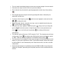
1
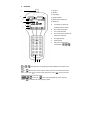
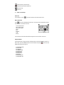
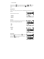
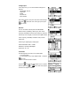
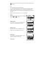
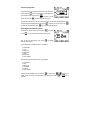
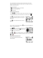
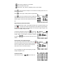
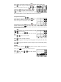
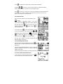
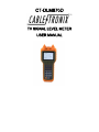
CT-DLM870D
TV SIGNAL LEVEL METER
USER MANUAL
1.
Overview
(1) RF input
(1)
(2) Speaker
B
C
(2)
(3) LCD display
(4) Charger indicator
A
(5) RS232 communication port
D
(6) DC-IN port
(3)
E
A.
F
G
The battery icon shows the
remaining power of battery.
B.
The current channel plan.
C.
The current test mode.
D.
The current channel number and
video carrier frequency.
E.
The signal strength.
F.
Signal level bar.
G.
Soft keys of function menu,
corresponding
(4) (5) (6)
Functional keys corresponding to functions indicated on the bottom of the
screen.
to
Numeric keys. used for input of number, or short-cut to test mode in the main
menu. In test mode,
is used for saving test result as a file.
is used to enter file
management menu from the main menu.
Arrow keys.
number.
is also used as backspace key when inputing a
is used as a dot when inputing a number.
Channel input key and enter key.
Frequency input key and escape key.
Main menu key.
Power key.
2.
Power on and setup
Power On
To turn meter on, press
, the meter will “buzz” and enter the main menu.
Menu instruction
Press
, the meter will display the main menu. The main menu includes below items in
according with the number in the icon.
1
2
3
4
5
6
7
8
Level measurement
Auto measurement
Spectrum analysis
Scan
Tilt
Voltage
C/N
Setup
You can directly enter each measurement using short-cut of the number in the icon.
Setup the meter
Set the meter before using instrument, all settings will be stored in the memory devices. In
Menu mode, press the ARROW buttons to select “SETUP” and press
display items as shown in Figure 2.
01
02
03
04
05
06
07
08
09
10
SHUTDOWN TIME
LEVEL UNIT
LANGUAGE
CHANNEL PLAN
CONFIG PLAN…
EDIT PLAN…
CREATE PLAN…
RESTORE
SOFTWARE VER.
HARDWARE VER.
, the screen will
11. SERIAL NUMBER
Using arrow keys or
select the desired item and then press
or
using arrow keys or
toggle the option, then press
to confirm the
or
to enter,
setup.
Shutdown time
In order to save energy, this meter can be set to automatically shut down when there is no
operation.
Automatic shutdown time options:
10minutes
20minutes
30minutes
Always on
Level unit
The current unit of measurement shows in the bottom of the
screen and you can toggle among below units:
dBuV
dBmV
dBm
Language
Chinese
English
Channel Plan
Using arrow keys select the item and press
setup, press
then press the
to enter the
to select the desired channel plan, and
again to save.
Configure plan
In this setup menu, you can set the default settings of all
channels.
1 Bandwidth2 Audio IF
3 Digi mode
4 Mode
5 Symbol rate
6 Save settings
After setting all items, using arrow keys select “Save settings”
and press
, and select “YES” in the pop-up then press
to confirm.
Edit Plan
The user can edit the channel plan items INCLUDING:
Channel number, availability, channel type, video carrier
frequency, bandwidth and sound carrier frequency; when the
channel type is set to digital, it can also be the digital channel
center frequency, bandwidth, modulation mode, and the
symbol rate.
Channel Type: digital signal / analog signal
Channel bandwidth: 1MHz - 9.9MHz
Modulation: 16/32/64/128/256QAM
Symbol rate: 1M - 7M
Create Plan
The following steps can create a user channel table:
1. Connecting cable.
2. In the “SETUP” menu, select “CREAT PLAN…” and press
to enter.
3. The unit will show below content:
Using the
to select the channel plan of your TV system
and then press the
or
bar shows the degree of created.
key to start. The progress
When finished, using arrow keys select YES to preserve and select NO to escape, then press
to confirm.
Note:
The unit needs to access a cable television system.
The unit will automatically select the channels with signal strength greater than -20dBmV
(40dBuV or -67dBm) and collect them into the user channel plan, recognizing analog or
digital channel. However, due to the complexity of the actual signal, the user may also need
to re-edit it.
Users can edit the user channel plan in the menu of “EDIT PLAN…”
Restore
If you want to set the unit to factory default, select “RESTORE”
and press
or
to confirm
Software version
In the “SETUP” menu, select the "SOFTWARE VER." The
software version will be displayed like below figure:
Hardware version
In the SETUP menu, select the “HARDWARE VER." The
hardware version will be displayed like below figure:
Serial number
In the SETUP menu, select “SERIAL NUMBER". The serial
number will be displayed like below figure:
3. Start to Use
Save and manage files.
In any test modes, you can save test result as a file and review
in future. Press
, there will be a pop-up “Input Filename”,
input the file name here and press
will be saved. Press
to confirm. The file
to cancel and quit the pop-up.
To manage the saved file, press “9” in main menu and you will enter file management mode.
Using arrow button highlight the file and press
to delete the selected files, press
to select one or more files, press
to review the highlighted file.
Single Digital Channel Measurement
or directly
In main menu, select “LEVEL” icon and press
press
to enter single channel measurement mode.
First set the current channel type. Press
channel setup window.
to display
If the channel type is digital channel, it will display:
1. Channel NO.
2. Type
3. Frequency
4. Bandwidth
5. Mode
6.Symbol rate
7. Save settings
If the channel type is analog channel, it will display:
1.
2.
3.
4.
5.
6.
Channel NO.
Type
Frequency
Bandwidth
Audio IF
Save settings
Using arrow key highlight an item and press
to enter, using
toggle options or directly enter parameter using keypad, and press
confirm.
arrow key to
or
key to
In the single digital channel measurement mode, the channel number is shown “CHD”
instead of “CHV” that the analog channel number is shown. In the middle of the screen it
displays the digital average power.
Soft key function definition
Enter the spectrum analysis of current channel
QAM, enter QAM analysis mode
Channel setup
Change the Channel under Test
1. Press
keys to change the channel number in the sequence of channel plan.
2. Using the keypad directly input the desired channel to be measured, and press
.
to enter spectrum analysis of current channel
Press
mode, for detailed operation, please refer to 3.3 spectrum
measurement.
to enter the QAM measurement, as shown in
Press
Figure:
Enter the symbol rate using keypad and press
parameter – MODE (modulation type).
Using
again to confirm and highlight next
arrow key toggle the modulation type until
it shows the correct option and press
Press
again to confirm.
to fresh the measurement.
Press
or
to enter constellation analysis. To zoom
in the display, using arrow keys to highlight the quadrant you want to zoom in and press
or
.
Single Analog Channel Measurement
In the single analog channel measurement mode:
Soft keys definition:
Enter spectrum analysis of current channel
Enter A/V measurement mode
Channel NO., Type, Frequency, Bandwidth, Audio IF, Save settings
to enter the spectrum analysis of current channel. For details, please refer to 3.3
Press
spectrum measurement.
Press
to set the type of analog channel or digital channel.
Press
to enter A/V measurement mode, simultaneously
display the channel audio and video carrier frequencies and
signal strength, as well as the relative difference between the
two.
Single Frequency Measurement Mode
In channel measurement modes, using keypad manually input any desired frequency and
press
. If an audio carrier exists on this frequency it will be heard through the speaker.
As this unit is equipped with an FM demodulator, this will measure signal strength of any
transmitted FM signal, and play the audio.
In frequency measurement mode, press
continuously,
the cursor blinks indicating the step of 100MHz, 10MHz, 1MHz,
100KHz, 10KHz, you can increase or decrease the frequency
by pressing
keys in the step where the cursor is
located.
Channel Audio Carrier Signal Strength
In the single analog channel measurement mode, press
to shift the unit between video carrier frequency mode (shows
CHV in the channel number) and Audio carrier Frequency
mode (shows “CHA” in the channel number).
The unit will display the audio carrier frequency, the signal
strength and play the audio.
3.2 Auto test mode.
In the main menu, press
keys until the unit
shows “AUTO” in the bottom of screen, press
Press
, the meter enters auto test mode.
to enter setup of auto test channels, you can
select up to 8 channels for auto test. Using
highlight the desired channel and press
select. Press
keys
or
to
to get back to auto test menu, press
and the selected channels will be tested and the signal
level of analog channel or power of digital channel will be shown in the list.
3.3 Spectrum measurement
In the main menu, press the
keys until the unit
shows “SPECT” in the bottom of screen, press
, the
meter enters spectrum measurement mode.
Using keypad input center frequency and press
, or input
, the unit will enter single
channel number and press
channel spectrum analysis mode and the center frequency is the channel center frequency
and the bandwidth turns to 9MHz.
Using
toggle the cursor of center frequency, then using
tune the frequency.
Press
level.
, then using
Press
adjust the reference
key to move the marker.
Press
to enter next page of soft keys.
Press
20dB.
to toggle the DIV setting of the testing graphic among: 1dB, 2dB, 5dB, 10dB,
Press
to toggle the bandwidth of spectrum analysis in steps of 4.5MHz, 9MHz, 27MHz,
54MHz, All.
3.4 Scan
In the main menu, press the
screen, press
key until the unit shows “SCAN” in the bottom of
, the meter enters SCAN measurement
mode.
and using
Press
level by step of 5dB.
adjust the reference
Press
to toggle the DIV setting among 1dB, 2dB, 5dB, 10dB, 20dB.
Press the
arrow keys, you can move the marker, the channel bar that the
marker located will show on the screen, as well as signal strength.
Press
to “zoom in” or “zoom out”. You can move the marker to view the channels out
of the screen. The number to display at a time depends on the screen. It is about 100
channels when zooming out to the maximum.
3.5 Tilt Measurement
In the main menu, select the TILT measurements, press
to enter.
Signal strengths of 8 channels display in the screen
synchronously. Using
toggle the DIV among 1dB, 2dB,
5dB, 10dB, 20dB. Press
to view the testing results in list
instead of graphic bar. Press
quit to previous menu.
In TILT mode, press
again or press
to
to enter the setup menu. You can
set up to 8 channels for TILT test here. Using
highlight the desired channel and press
to confirm after selection. Press
channel list and press
to select. Press
to view the
to quit to previous menu.
The max signal strength, min signal strength and their
difference display on the screen.
3.6 Trunk Voltage Measurement
In the main menu, select the “VOLTAGE” item, press
, the
meter will enter the voltage measurement mode. As shown in
below figure.
The meter will automatically identify “AC” or “DC” of the trunk
voltage, and display on the screen. The battery voltage also
display on the bottom.
Typically at the cable demarcation point outside the structure, there will be no trunk voltage.
3.7 Carrier to Noise Ratio Measurement
In the main menu, select the “C/N” item and press
enter the signal noise ratio measurement mode.
to
Note:
The function affects when the signal input level is greater than 60 dBuV.
4. Power supply
Power Supply
The meter is equipped with a high performance rechargeable battery. The voltage of batter
can be monitored automatically, the meter shall alarm when power is low. Press the voltage
measurement key, the instrument shall show the battery voltage.
The meter powers off automatically if there is no operation for set power-off time.
Please use only the charger provided with the meter, using any other battery charger may
overheat or distort the meter, or cause fire, injury or harm to the environment and will void
the warranty. The indicator on the front panel will turn red when the instrument is being
charged. The charging can be done when both the meter is power on and power off.
CT-DLM870D
TV SIGNAL LEVEL METER
Quick Start Guide
•
Make certain that the battery is fully charged.
•
Turn the unit ON by pressing
•
The unit will “buzz” and enter the main menu after displaying the logo and model
number.
•
Using arrow keys highlight the SETUP menu and press
.
key or directly press
on keypad, the meter will enter SETUP menu and display setting items.
•
Using arrow keys, highlight “SHUTDOWN TIME” and press
TIME” mode of your choice, and then press
•
to confirm.
Next to “SHUTDOWN TIME”, select the “LEVEL UNIT” option. The display shows
three available units of measure, “dBµV” “dBmV” and “dBm”. It is common in the
industry to refer to RF signal strength as dB. In reality, the unit of measure is dBµV or
dBmV varying from different countries. Using the arrow keys, select the desired unit and
press the
•
•
•
•
•
, select a “SHUTDOWN
key to confirm.
Next in the “LANGUAGE” item, select the desired language.
In the next item “CHANNEL PLAN”, select the desired channel plan.
Next item is “CONFIG PLAN”. Here you can set the default settings of all channels.
Next item is “EDIT PLAN”. Here you can set the parameters of each single channel.
Next item is “CREATE PLAN”. Here you can automatically enable all channels of
selected channel plan those are higher than -20dBmV, 40dBuV or -67dBm, and disable
others. Press
to enter the menu, connect the meter to CATV system, using
select the channel plan of your TV system and then press
or
to start. The
progress bar shows the degree of created, when finished, using arrow keys select YES
to preserve and select NO to escape, then press
•
•
Press the
or
to confirm.
to return to the main menu.
Using the arrow keys to select “LEVEL” and press
, or directly press numeric
key, you will enter the signal level test mode.
•
The display will show the channel number, video frequency and video carrier signal
strength.
•
Using a supplied “F” coupler, connect the CATV signal lead to the input located at the
top of the instrument.
•
•
•
The unit should immediately display the video carrier signal strength of current channel.
Press the arrow keys to move to the next or previous channel.
Direct channels may be entered by pressing appropriate number keys, then pressing
.
•
Direct single frequencies may be entered by pressing MHz button, followed by the
appropriate number keys
•
To select a direct frequency, press
•
to change the value.
To test the digital channel, using the arrow keys, move to a digital channel and press
•
until the cursor highlights a value and use the
to show channel setting window.
Using the arrow keys, highlight “TYPE” and press
. Using arrow keys change the
type to “Digital” and show options of digital channel. Enter correct parameters and
press
. Or you can directly quit by pressing
, the settings will be saved
automatically.
•
•
•
The channel number will become “CHD” instead of “CHV”. The channel power will show
, the display enter QAM analysis menu and show the results
on the screen. Press
.
of “MER”, “BER” as well as the graphics of constellations after pressing
The instrument will now display the video carrier strength of the selected channel on the
display. It is this carrier signal that is critical. Typical cable company requires this signal
be within ±5dB of 0, at the demarcation point outside the structure, as well as all cable
outlets within.
Note that signal strength of considerably lower than 55dBuV/-5dBmV may still provide
satisfactory reception, depending upon the quality and size of the connected television
receiver.