1
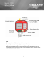
WiLARM-MICRO
GSM Module
Installer Manual
Version: 2.0
WiLARM-MICRO
GSM Module
Installer Manual
Version: 2.0
Content
WiLARM MiCRO GSM Module…………………………………………………………………………... 1
The parts of the module………………………………………………………………………………........ 3
Mini USB connector………………………………………………………………………………………….. 3
Terminal contacts…………..…………………………………………………………………………………. 3
Power supply……………………………………………………………………………………………………. 3
Inputs and outputs………………………………………………………………………………………..…… 3
Power monitoring input…………………………………………………………….………………………. 3
LEDs…………………………………………………………………………………………………………..…….. 4
Operation of the LEDs…………………………………………………………………..…………..……….. 5
Push button…………………………………………………………………………..…………………..………. 5
Deleting the configuration (master reset)………………………………………………….…….….. 5
Erasing and rewriting the internal drive……………………………………………………..………. 5
Copying the software and documentation onto the internal drive………………………… 6
Refreshing the internal firmware…………………………………………………………..……………. 6
SIM holder……………………………………………………………………..………………………………….. 7
Antenna connector…………………………………………………………………………………………….. 7
Prepare for the installation………………………………………………………………………………………. 7
Programming using WiLARM Commander software…………………………………………………. 7
Programming with SMS commands……………………………………………………………..…………… 8
Controlling the GSM module with commands…………………………………………………………… 9
Troubleshooting…………………………………………………………………………………………………….. 10
2
WiLARM-MICRO
GSM Module
Installer Manual
Version: 2.0
The parts of the module
Mini USB connector
The WiLARM GSM module can be programmed via the mini USB connector. When it is
connected, WiLARM as a new drive called “WiLARM” appears in the “my computer” icon on the
desktop. Clicking onto the drive the WiLARM Commander software and a PDF documentation
appear.
The internal software of the module can be refreshed via the mini USB connector. The
“WiLARM_Upgrader” software documentation includes the whole detailed user manual.
Terminal contacts
The power supply and the different inputs and outputs can be connected to the GSM module
via the terminal contacts.
Power supply
The module operates from 9-12 Volt DC. The idle current consumption of the module is 30mA,
but during communication it can reach 2 Amperes as well.
Inputs and outputs
The contact inputs can operate in normally closed (NC) referenced to the ground (GND) or
normally opened (NO) modes. Changing the default state starts the alarm.
The multiport inputs are contact operated as well, but with the WiLARM Commander Software
they can be configured as open collector outputs. In this case the load current can be maximum
100 mA, they can be configured similar to the relays.
Power monitoring input
Module measures the accurate value of the input power. Can be parameterized, like contact
inputs. Additionally user can set lower and upper voltage values, which exceeded, module will
send alarm.
3
WiLARM-MICRO
GSM Module
Installer Manual
Version: 2.0
LEDs
The green and the red LEDs show the module status in operation.
The red LED shows some kind of activity,
the green LED shows the strength of the network signal strength in normal operation.
When the green and the red LEDs are blinking together, then the device does not work, the
number of the blinking shows an error code. The error code can be seen on the status window
of the WiLARM Commander software.
4
WiLARM-MICRO
GSM Module
Installer Manual
Version: 2.0
Operation of the LEDs
LED operation chart
Green LED operation
Lighting continuously
Meaning
It can not connect to the network
1-2 blinks
Low network signal strength, another place or
external antenna is recommended
3 blinks
Reasonable network signal strength, a test call is
suggested
4 blinks
Good network signal strength
5 blinks
Excellent network signal strength
Green and red LEDs blink together
Error code
1 blinks
2 blinks
3 blinks
Initializing
GSM module error
SIM card is missing
4 blinks
SIM card is locked with PIN code, but the PIN code
has not given in the programmer software
Pushbutton
The pushbutton is used for different adjustments of the GSM module, erasing the memories
and upgrading the internal firmware.
Deleting the configuration (master reset)
-
Unplug the device (remove the external power supply), unplug the USB cable
-
Push the reset button while the device is switched off
-
Plug the power supply and release the Reset button immediately
-
The two LEDs of the module light up and blink once
-
When both LEDs turn off, push the Reset button again
-
The green LED shows, that the Reset process is done
-
Unplug the device again
Erasing and rewriting the internal drive
The internal drive of the GSM module can be rewritten only after erasing if you want to upload
a new WiLARM Commander software or documentation.
5
WiLARM-MICRO
GSM Module
Installer Manual
Version: 2.0
-
Unplug the device (unplug the external power supply), unplug the USB connector
-
Push the reset button while the device is switched off
-
Plug the power supply and release the reset button immediately
-
Both LEDs of the module light up and blink one
-
When both LEDs turn off, wait until they light up again
-
When both LEDs turn off again – the second time-, push the Reset button again
-
The green LED signs, that the erasing process has happened
-
Unplug the device
Copying the software and documentation onto the internal drive
After deleting the internal drive, plug the power supply and then the USB cable to the module.
-
In “My computer” the module appears as a new drive on the desktop
-
Format the drive, check the size (3 Mb), the volume label should be “WiLARM”
-
Copy the necessary software and documentation to the drive
-
Unplug the device
Refreshing the internal firmware
-
Launch the Wilarm_Upgrade.exe software
-
Unplug the device (remove the power supply), unplug the USB connector
-
Hold on the reset button and plug the USB cable
-
The LEDs light at low intensity, which means, that the module is in BOOT mode
Attention! If you do not start the refreshment within 10 seconds, the module automatically
leaves BOOT mode and restarts itself.
-
Open the firmware with the Open+Upgrade button
6
WiLARM-MICRO
GSM Module
Installer Manual
Version: 2.0
-
The refreshment of the internal software has been starting
-
At the end of the process the PASS title signs the successful finish
-
Restart the WiLARM GSM module
SIM holder
The holder of SIM card, (the SIM was bought from the network service). The device is card
independent, so it accepts any kind of cards. It is better to switch off the PIN request of the SIM
card, if it is not possible, the PIN code can be adjusted in the WiLARM Commander menu.
Antenna connector
Standard SMA/F connector. The supplied stick antenna can be connected here or the optional
types with extension cable.
Prepare for the installation
-
Insert the SIM card to your mobile phone, disable voice mail service, activate the callerID
sending, do a network signal strength measurement
-
Insert a SIM card without a PIN code request into the GSM module, connect the power
supply and do a network signal strength measurement with the green LED
Programming using WiLARM Commander software
All of the available functions of the module can be adjusted via the WiLARM Commander.exe
software. After connecting the power supply and the USB, the module appears as a “WiLARM”
drive in “My computer” on the desktop. The content of it can be seen while opening: the
software and the documentation in PDF format.
The software is universal, all WiLARM modules can be programmed with it. After connecting it,
the software recognizes the type of the module and the proper setting screen appears. If the
module is not connected, then all parameters can be seen regarding all types of modules.
7
WiLARM-MICRO
GSM Module
Installer Manual
Version: 2.0
The WiLARM Commander software has a built-in help. The cursor can be stopped on any kind
of place of the menu, the help will appear for the use of the current menu.
Programming with SMS commands
The main parameters of the GSM module can be programmed via SMS commands as well. The
adjustment of the GSM module can be done with the programmer SMS commands as well as
the smaller modifications after the installation (dialed phone numbers, inputs, output
parameters, etc.).
The detailed commands are available with examples in the SMS commands table,
“Programming SMS commands” section.
Command description
Example
Commands for programming
Changing the security password
1234pin4321
Where 1234 is default, 4321 is the
new code
1234pin:4321
Setting up the phone numbers
1234setnum:number1,number2,......, 1234setnum,06201234567,06301234567,06701234567,d,n,n
number5
When we write "d" the place of a
phone number, then it will be
deleted,
When we write "n" the place of a
phone number, it won't be changed.
Setting up the inputs
1234setin:in1:invertation,input
type,sms notification,phone
notification,
in2:invertation,input type,sms
notification,phone notification
inverted „i”- invertation or „n” – not
inverted
input type:
1- Not used
2- 24 hour
3- Autoalarm
4- Arm/Disarm
1234setin:in1:i,2,s12345,c1234,in2:n,3,s1,c12,.
Where the first input is inverted, 24 hour, SMS sending to 1-5 phone numbers, Phone call to 1-4
phone numbers,
The second input is not inverted, it is in Autoalarm mode, SMS sending to the first phone number,
phone call to 1-2 phone numbers.
Setting up the first input only:
1234setin:in1:i,1,s12345,c1234,.
Setting up the second input only:
1234setin:in2:i,4,s12345,c1234,.
„s” and the number, where we want
to send the SMS
Phone notifications:
„c” and the number, where we want
to send the phone notification
8
WiLARM-MICRO
GSM Module
Installer Manual
Version: 2.0
Sending phone number to the SIM card
SIM:phone number.
1234SIM:+36301234567.
Deleting the phone number from the SIM card
SIM:phone numberd.
1234SIM:+36301234567d.
Deleting the +36301234567 phone number from the card
1234SIM:1234567d.
Deleting all 1234567 ended phone number from the SIM card
Setting up the clock
clk:YYYY,MM,DD,HH:MM,.
YYYY-year
MM-month
DD-day
HH-hour
1234clk:2011,02,30,11:21,.
It sets the GSM clock to February 25, 2012, 11 hour 21 minutes.
Controlling the GSM module with commands
The device can be controlled via the command SMS (test, arming, switching output, etc.)
The detailed commands are reachable with examples in the SMS commands table, “Controlling
SMS commands” section.
Control commands
Test request
1234t
In this case the GSM module
responds a status SMS about the
arming status of the inputs,
outputs, inner clock, temperature,
power voltage.
1234t
Turning off the inputs
outon
Turning on the inputs
1234outon:1.
activating the first output
1234outon:4.
activating the multiport 4
outoff
Turning off the inputs
1234outoff:1.
truning off the output 1
1234outoff:2.
turning off the relay 2 or the multiport output (bistable mode)
Arm mode on/off
on
1234on
off
1234off
GSM module RESET
1234reset
1234reset
9
WiLARM-MICRO
GSM Module
Installer Manual
Version: 2.0
Troubleshooting
Troubleshooting
Error descripition
Solution
ACT LED stays red during alarm.
The module can not send the message because the card is out of credit or
a wrong phone number was given. Check the SMS center number of the
module SIM card.
WiLARM Commander doesn't not recognize the module.
The USB cable is long. Try with a shorter cable or plug the cable directly to
the USB port of the computer. Check if external 12V power supply is
connected.
The caller phone number (GSM module) can not be seen.
The caller ID is disabled on the card.
The module sometimes does not call.
The very old cards (more than 10 years) could cause problem.
Caller identification does not work.
Check the service provider, that on the SIM card the caller ID for outgoing
calls is turned on. Check the caller ID of the controllable phone as well.
Check the "Only SIM reg. Number" at call settings as well as the phone
numbers have already typed to the SIM card.
10
Hungary-1115 Budapest
Csoka str. 7-13/A
Tel: +36-1-466-5665
E-mail: [email protected]
Web: http://www.wilarmsecurity.com


![[ Bedienungsanleitung ]](http://vs1.manualzilla.com/store/data/006727055_1-0b6d7ee6c7d78cc189f99691f7f6f129-150x150.png)