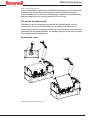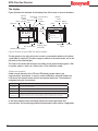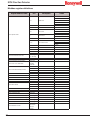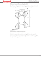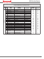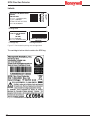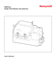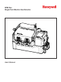
1
SPM Flex
Single Point Monitor Gas Detector
User’s Manual
SPM Flex Gas Detector
Introduction���������������������������������������������������������������������������������������������������������������� 5
Safety Information�������������������������������������������������������������������������������������������������� 6
Contact Information������������������������������������������������������������������������������������������������ 7
Glossary���������������������������������������������������������������������������������������������������������������������� 8
Product Overview������������������������������������������������������������������������������������������������������� 9
Battery operation�������������������������������������������������������������������������������������������������� 10
The handle (portable model)�������������������������������������������������������������������������������� 11
Opening the cover������������������������������������������������������������������������������������������������ 11
Main power rocker switch������������������������������������������������������������������������������������ 12
Turning the detector on and off���������������������������������������������������������������������������� 13
Navigation������������������������������������������������������������������������������������������������������������� 14
Menu Map������������������������������������������������������������������������������������������������������������� 15
Loading a Chemcassette cartridge���������������������������������������������������������������������� 17
Wiring and tubing����������������������������������������������������������������������������������������������������� 19
Typical fixed installation topologies��������������������������������������������������������������������� 19
Wiring diagrams���������������������������������������������������������������������������������������������������� 21
4-20 mA wiring������������������������������������������������������������������������������������������������������ 22
Modbus register definitions���������������������������������������������������������������������������������� 24
Setup������������������������������������������������������������������������������������������������������������������������� 26
Installation drawing����������������������������������������������������������������������������������������������� 26
Mounting options�������������������������������������������������������������������������������������������������� 26
Dimensions������������������������������������������������������������������������������������������������������������ 27
Standard mounting bracket���������������������������������������������������������������������������������� 28
Backward-compatible mounting bracket������������������������������������������������������������ 29
In-line filters����������������������������������������������������������������������������������������������������������� 30
Optional sampling wand��������������������������������������������������������������������������������������� 30
Attaching the shoulder strap�������������������������������������������������������������������������������� 31
Operation ����������������������������������������������������������������������������������������������������������������� 32
Controls����������������������������������������������������������������������������������������������������������������� 32
Setup menu����������������������������������������������������������������������������������������������������������� 38
Troubleshooting�������������������������������������������������������������������������������������������������������� 42
Maintenance������������������������������������������������������������������������������������������������������������� 46
Storing the detector���������������������������������������������������������������������������������������������� 49
Recycling��������������������������������������������������������������������������������������������������������������� 49
Storing Chemcassette® cartridges����������������������������������������������������������������������� 49
Labels������������������������������������������������������������������������������������������������������������������������ 50
Detectable Gases����������������������������������������������������������������������������������������������������� 51
Specifications ���������������������������������������������������������������������������������������������������������� 52
Accessories and Parts��������������������������������������������������������������������������������������������� 53
Certifications������������������������������������������������������������������������������������������������������������ 56
Warranties����������������������������������������������������������������������������������������������������������������� 57
SPM Flex warranty������������������������������������������������������������������������������������������������ 57
Chemcassette® cartridge warranty���������������������������������������������������������������������� 57
Index������������������������������������������������������������������������������������������������������������������������� 60
3
SPM Flex Gas Detector
4
SPM Flex Gas Detector
Introduction
The SPM Flex gas detector is an extractive gas monitoring system that draws gas
samples locally or from a remote point to a Chemcassette® tape-based optical gas
detection system. A wide range of toxic gas Chemcassette cartridges are available
that enable detection of gases used or generated in semiconductor manufacturing
and industrial environments.
The SPM Flex gas detector, available in wall mounted and portable versions,
locally displays gas concentration, alarm, fault and status information via its backlit
color LCD and LEDs. A simple to use 4-button keypad adjacent to the display
provides the ability to set-up, review, operate and make changes to the detector’s
configuration. The intuitive display and menu structure are designed to require
minimal training. The SPM Flex has a local audio alarm with user-configurable
output levels. The detector can be used both indoors and outdoors in a wide range
of weather conditions.
The detector has flexible power and communications capabilities. These include
3 on-board relays, 4-20 mA analog output and Modbus/TCP outputs for signal
and service connectivity. The gas detector is equipped with a USB port for
configuration-sharing firmware updates and data downloads. For web-enabled
devices, web pages are available via the Ethernet port.
Standard operation conditions
The SPM Flex gas detector is designed for use in temperatures between 32ºF
and 104ºF (0ºC and 40ºC) and relative humidities between 0 and 100% (the
relative humidities are limited by tape and calibration). The sample line will require
additional hardware to remove moisture in high relative humidity conditions where
condensing may occur (the sample must be non-condensing). Dry conditions may
require humidification.
High-altitude applications
The SPM Flex pump is optimized for operation at altitudes between –1000 feet
(–305 meters) and 3000 ft. (945 m) above sea level. At altitudes above 3,000 ft.
(915 m), up to a maximum of 6,000 ft. (1,830 m), contact Honeywell Analytics for
calibration. (At 6,000 feet, pump capacity is reduced 18% and a flow-system
adjustment to the bypass valve is required. This must be performed by a Honeywell
Analytics certified technician. Contact Customer Service.)
5
SPM Flex Gas Detector
Safety Information
! DANGER
Danger notices contain information that could prevent death or serious injury.
! WARNING
Warnings contain information that could prevent injury or equipment damage.
! CAUTION
Caution notices contain information that could prevent equipment damage.
NOTE
Notes contain helpful information.
6
SPM Flex Gas Detector
Contact Information
Find out more:
www.honeywellanalytics.com
Americas
Honeywell Analytics
405 Barclay Boulevard
Lincolnshire, IL 60069
Tel: +1 847 955 8200
Toll free: +1 800 538 0363
Fax: +1 847 955 8208
[email protected]
Europe, Middle East, and Africa
Life Safety Distribution AG
Javastrasse 2
8604 Hegnau
Switzerland
Tel: +41 (0)44 943 4300
Fax: +41 (0)44 943 4398
[email protected]
Asia Pacific
Honeywell Analytics Asia Pacific Co., Ltd.
#701 Kolon Science Valley (1)
43 Digital-Ro 34-Gil, Guro-Gu
Seoul, 152-729
Korea
Tel: +82 2 6909 0321
VOIP: +8 5401 0321
[email protected]
Technical Services
[email protected]
www.honeywell.com
7
SPM Flex Gas Detector
Glossary
Term
Description
An analog communication method using a current
loop to indicate concentration readings and fault
status.
An easy-to-install case that carries Honeywell’s
Chemcassette® cartridge Chemcassette tape. Cartridges are specific to
different gas types/families.
Commonly used network technology for wired Local
Ethernet
Area Networks.
The unit is actively monitoring the specified gas or
In monitor
family of gases
When configured, the SPM Flex will hold the alarm or
Latching alarm or fault
fault status active until the user performs an alarm/
fault reset.
Liquid Crystal Display
LCD
LED
Light Emitting Diode
Communications protocol running over Ethernet that
Modbus TCP
is commonly used for communicating with industrial
devices.
An alert in which the SPM Flex will reset
Non-latching alarm or
automatically when the condition is no longer
fault
present (i.e., the detector does not have to be reset
by the user).
Out of monitor
The detector is on but idle
An electrical-operation output switch that can be
Relay
used to indicate the presence of alarm and fault
conditions.
Time Weighted Average, the average exposure to a
harmful gas, usually calculated over a period of eight
TWA
hours (a the typical workday).
Universal Serial Bus is an industry standard
communications protocol and bus that is commonly
USB
available on personal computers.
Volts of Direct Current
VDC
4-20 mA loop
8
SPM Flex Gas Detector
Product Overview
The SPM Flex gas detector is available in two configurations, portable and fixed.
The portable model is equipped with a handle assembly and a shoulder strap.
The fixed unit is supplied with a mounting bracket. If replacing an old SPM
detector, a retrofit bracket is available (these are shown on pages 28 and 29).
All units are supplied with a power adaptor1 and cable, a CD containing the user
manual, and a printed quick start guide.
! WARNING
Operate and service the SPM Flex gas detector only as specified in this manual
and the accompanying quick start guide. Failure to do so may impair the
protection provided by the detector and may also void the warranty.
Initial setup
Prior to use, the detector requires some minimal setup:
• Unpack the unit (save the packaging to re-use for service requests).
• Read the quick start guide and this manual.
• Install a filter at the unit or at the end of a sample line
Portable detectors
• Connect the power adaptor (in a dry, indoor location)
• Charge for at least 4 hours (the detector can be used while being charged)
• Open the detector’s cover
• Remove the rocker switch cover
• Turn the rocker switch to the on position
• Replace the rocker switch cover
• Remove the paper optics card from the gate (save the card for later use)
• Load a chemcassette
• Configure the detector and begin to monitor (see pages 15-16 for basic
display usage)
• See detailed Operation (pages 32-41) and Optional accessories (pages 53-55)
Fixed detectors
• Install the wall-mount bracket and mount the detector to it (see pages 28-29)
• Wire in accordance with local electrical codes utilizing a trained electrician
(see pages 19-25)
• Input
• Honeywell-supplied power adaptor (indoor, dry location use only) or
• 24 VDC power supply
• Signal (as desired)
• 4-20 mA
• Relays
• Ethernet
• Open the detector’s cover
• Remove the rocker switch cover
• Turn the rocker switch to the on position
• Replace the rocker switch cover
• Remove the paper optics card from the gate (save the card for later use)
1 FSP Group Model FSP135-AAAN rated 1 5.62A / 24V (UL Listed QQGQ (E190414))
9
SPM Flex Gas Detector
•Load a Chemcassette cartridge
•Configure the detector and begin to monitor (see pages 15-16 for basic display
usage)
•See detailed Operation (pages 32-41) and Optional accessories (pages 53-55)
Additional accessories
•External dust filters (required on inlet)
•Tubing
•Sampling wand
•Mating signal connectors for fixed installations
The ports of a typical installation is shown in the figure below.
Exhaust out port
Sample in port
Power connector
Ethernet
connector
Relays or 4-20 mA connector
Figure 1. terminals and ports
Battery operation
The SPM Flex gas detector is supplied with a power supply/charger than can
connect the detector’s power connection and a standard wall outlet. (Ensure that
the correct power cable has been ordered for local operation.) The power supply/
charger is designed for indoor, dry-location use only. The lithium-ion battery pack
provides continuous operation of 6+ hours, depending on sampling conditions
and unit configuration. The battery’s charge time is typically 4 hours. The
detector can be operated while its battery is being charged (this may increase
the charge time). Because batteries discharge slowly when not in use, Honeywell
Analytics recommends keeping the detector connected to the power supply/
charger when not in use.
! WARNING
•The battery is not field-replaceable. Return the unit to Honeywell Analytics if
a battery replacement is necessary.
•Risk of fire and burns. Do not open, crush, heat above 140ºF (60ºC), or
incinerate the battery. Follow manufacturer’s instructions.
10
SPM Flex Gas Detector
How to extend battery life
Power consumption is optimized to extend battery life when not in monitor mode.
In addition, the unit should not be exposed to extreme temperatures which
shortens battery life. The time before recharging is required can be extended by
taking the detector out of monitor mode when it is not in use.
The handle (portable model)
The detector can be conveniently carried with the optional handle, which is
mounted onto the cover at three locations. If necessary, the handle can be
removed by the user by removing two bolts. All of the detector’s functions can be
performed with the handle attached. The handle swings out of the way for access
to the Chemcassette cartridge area.
Opening the cover
Figure 2. Opening the detector cover
11
SPM Flex Gas Detector
Release the cover by first unscrewing the handle pin. Pivot the handle up as
shown in the illustration and push down the four latches (two on each side).
The detector cover will then be free to swing open, allowing a Chemcassette
cartridge to be inserted or replaced, the power switch to be turned on or off, or
the USB data port to be accessed.
Main power rocker switch
Rocker switch cover
Main power rocker switch
Figure 3. SPM Flex main power rocker switch
After the detector’s cover is open, use a Phillips screwdriver to remove the
rocker switch cover. Turn the main power rocker switch to the on position and
replace the rocker switch cover.
The detector can now be turned on.
12
SPM Flex Gas Detector
Turning the detector on and off
Press and hold the Power/Cancel button until the green LED begins blinking. The
detector will begin a startup sequence that lasts about 30 seconds.
The four LEDs provide at-a-glance information about the current state of the
detector:
LEDs (red, green, yellow, blue)
Figure 4. SPM Flex LEDs
LED
Red
Green
Yellow
Blue
solid
Description
Alarm 1
blinking
Alarm 2
blinking
The detector is active
solid
blinking
solid
Maintenance fault
Instrument fault
Connected to external power
To turn the detector off, press and hold the Power/Cancel button for 5 seconds or
select “Power Off” from the menu.
13
SPM Flex Gas Detector
Navigation
Display
Power/Cancel
Accept/Select
Up arrow
Down arrow
Figure 5. SPM Flex controls
All SPM Flex menus are navigated by the four buttons shown in Figure 5.
Pressing either of the arrows or the Accept/Select button will access the menu
from the main display screen. The arrows also are used to scroll up and down
through lists of options. The Accept/Select button is used to initiate a highlighted
option. During navigation, the Power/Cancel button will cancel a command or,
when pressed for more than 3 seconds, it will exit to the main display.
14
SPM Flex Gas Detector
Menu Map
Main Menu
Login/Logout
Reset Alarms & Faults
Reset all
Silence
audio alarm
Monitor Mode
Out of
Enter
monitor mode monitor mode
Change Chemcassette
Review Mode
Event
History
Chemcassette
Gas
Settings
Network
Additional
Status
Output
State
Trend/Plot
Security
Configuration
Manager
Software
Maintenance
Inhibit
Summary
4-20 mA
Current Loop
Flow Characterization
Open/Close
Gate
Update
Program
General
Monitoring
Latching
Outputs
Network
Optics
Verification
Simulate
Force
Relay
Setup
Test
Force
4-20 mA
Power Off
The SPM Flex detector’s menus are easily navigated. As an example, this is how
a user could review the detector’s gas settings when starting from the In Monitor
screen:
1. Press the Up Arrow > to return to the Main Menu.
2. Press the Down Arrow 4 times to highlight the Review Mode option.
3. Press the Accept/Select button to enter Review Mode.
4. Press the Up Arrow or Down Arrow until the Gas settings option is
highlighted.
5. Press the Accept/Select button to display the Gas Summary.
To return to the detector to the In Monitor display, press the Power/Cancel button
three times to back out of the Main Menu options.
15
SPM Flex Gas Detector
The display
Figure 6 shows the elements of the display that will be seen in various situations.
Alarm 1/
Instrument Concentration
Alarm 2/
Fault trend
Inhibit Maintenance
indicator
Mute indicator Fault
Status bar
Menu
title
15:42:01
15:42:01
2
0 . 123
ppm
5.678
Menu
options
Main menu
Login / Logout
Reset alarms/faults
1.234
H2S - Hydrogen Sulfide
Monitor mode
Change Chemcassette
In monitor
Gas name
Monitor
mode
Indicator Battery
Clock
indicator
Units
Gas concentration
Monitor mode indicator
Bar graph
w/upper, lower
alarm limits
Highlighted
option
Scroll bar
Figure 6. Elements of typical SPM Flex detector displays
The bar graph on the right shows the current concentration relative to the Alarm
1 and Alarm 2 setpoints. (The bar’s range is relative to the alarm levels, not to the
full scale of the selected gas).
The color of the status bar changes according to the system status (green = OK/
in monitor, yellow = fault, red = alarm, blue = Out of Monitor mode).
Display and navigation
Under normal operation the LCD and LED display system status, gas
concentrations, and alarms. In set-up, review, calibration, and test modes, the
LCD shows the relevant menu options and system status bar. The interface is
navigated using the four buttons:
Control
Up arrow
Function
Scroll up through lists of options
Down arrow
Scroll down through lists of options
Accept/Select
Accept or select a highlighted option
Power/Cancel
Power/Cancel will turn the unit on if it’s in the off state, will exit back to the previous menu level, and will
enter Reset mode (quick press), or Power Off mode (long press and hold) from the main display.
In the main display mode, the display shows the current gas name and
concentration, the monitoring states and faults and/or alarm status, if applicable.
16
SPM Flex Gas Detector
Loading a Chemcassette cartridge
Close the Chemcassette cartridge door before putting the detector into Monitor
mode (this holds the Chemcassette cartridge in place). Take the detector out of
Monitor mode before opening the door.
NOTE
Chemcassette cartridges must be stored according to the manufacturer’s
guidelines when not in use.
Chemcassette
cartridge
Take-up spindle
Encoder
Optics gate card
Figure 7. The optics gate card and Chemcassette cartridge
1. If the detector’s handle is installed, release it by unscrewing the thumbscrew.
For fixed installations, skip to Step 3.
2. Tilt the handle up as far as possible.
3. Unfasten the latches on the sides of the detector (two on each side) that
secure the Chemcassette cartridge access cover.
4. The detector has slotted hinges. Lift up the cover slightly and then open it all
the way to the right.
5. Select the Change Chemcassette menu option and follow the on screen
instructions.
6. If required, remove the old Chemcassette cartridge. When prompted, snap
the new Chemcassette cartridge into place. It will fit in only one orientation.
The takeup spindle will “flutter” back and forth to allow easy installation.
7. To close the cover, position it over the base and press so that it contacts the
gasket uniformly.
8. Close the latches on the sides of the detector to secure the cover.
17
SPM Flex Gas Detector
If there is an error (i.e., the same cartridge was reinserted, the new cartridge has
expired, or an unqualified user is attempting to insert a cartridge that detects
a different gas than the last one), an error message will be displayed and the
installation will be canceled. If the installation is successful, a summary of the
current configuration will be displayed and the user can then choose whether to
enter Monitor Mode or exit the Change Chemcassette Mode out of monitor.
Removing a Chemcassette cartridge
1.
2.
3.
4.
Navigate to Maintenance > Open/Close gate.
Select “Open Gate.”
Remove the cartridge.
Select “Close Gate.”
Changing the selected gas
1. While out of monitor mode, navigate to Set-up > Monitoring > Gas.
2. Select “Current gas” and pick the desired gas from the selection box
3. Select “Save.”
Entering monitor mode
From the main menu, navigate to the “Monitor Mode” option and select “Enter
monitor mode.”
1. If a Chemcassette cartridge has been installed, the detector will enter Monitor
Mode.
2. If a Chemcassette cartridge has not been installed, a user with the necessary
passcode can inititate the Chemcassette wizard. Otherwise, the detector will
not enter monitor mode.
18
SPM Flex Gas Detector
Wiring and tubing
Typical fixed installation topologies
The SPM Flex gas detector has flexible installation options that allow the user to
select the one most suitable for a specific application. The detector is supplied
with weather-sealed connectors for power, Ethernet, and communications
(for relays or 4-20 mA). Any of the ports can be replaced with appropriate
connections in accordance with local codes (allowing the user to wire directly to
the terminal block). Install each detector near a dedicated circuit breaker.
! CAUTION
• The safety of any system incorporating the SPM Flex gas detector is the
responsibility of the assembler of the system.
• Position a permanently-installed SPM Flex gas detector so that it does not
interfere with access to the dedicated circuit breaker.
Electrical connection is made via conduit directly to ports or via the connector
(see Figure 1 on page 10). The terminals used are suitable for conductors of 24
to 14 AWG (0.5 to 1.8mm Dia.). The use of 16 AWG (1.5 mm dia.) conductors is
recommended.
! CAUTION
Use the supplied power adaptor/connector only. (The adaptor is rated for
indoor use only.)
19
SPM Flex Gas Detector
Ethernet connector
P8
P9
NO
Relay 2
NO
COM NC
Relay 1
NO
COM NC
+
Fault
COM NC
-
-
+
24 VDC
4-20 mA
4-20 mA
connections
Input power
connections
Relay
connections
top of
detector
Figure 8. SPM Flex connections
Terminal Module
The terminal module is located on the main PCB inside the gas detector. All
power, relay, and 4-20 mA connections to SPM Flex are made via this module.
Wire entry to the terminal module area is via the cable entry/conduit entry located
at the top of the detector.
This table shows the default wiring configuration for the communication
connector when installed by Honeywell Analytics. The relays are labeled for the
factory default but the configuration can be modified to have a single alarm and
separate faults.
Relay Terminal Connections
No.
Color
Assign to Relay
1
2
3
4
5
6
7
8
9
10
Brown
Red
Orange
Yellow
Green
Blue
Purple
Gray
White
Black
Alarm2 COM
Alarm2 NO
NC
Alarm1 COM
Alarm1 NO
NC
Fault COM
Fault NO
NC
NC
For 4-20 mA wiring, wires 1 through 8 would be disconnected and wires 9 and 10
would be used. Do not run 4-20 mA signals and relay signals in the same cable
bundle.
20
SPM Flex Gas Detector
Wiring diagrams
SPM Flex
Controller
+VE
24V+
1
RL
Signal
4-20 mA+
2
Current
Flow
-VE
24V-
3
Figure 9. 4-20 mA sink wiring diagram
SPM Flex
Controller
+VE
Signal
24V+
1
2
4-20 mA Current
Flow
RL
-VE
3
24V-
Figure 10. 4-20 mA source wiring diagram
Controller
SPM Flex
+V1
24V+
+V2
4-20 mA+
-V2
-V1
4-20 mA24V-
Figure 11. 4-20 mA isolated wiring diagram
21
SPM Flex Gas Detector
4-20 mA wiring
4-20 mA output is a three-wire connection that is configurable as sink, source, or
isolated, as shown in these following figures. Use an Allen wrench to remove the
wiring cover for access to the terminals. There must be a 200-600-ohm load on
the 4-20 mA line.
To ensure adequate resolution to overcome tolerance in the 4-20 mA reading, set
the full scale at an appropriate level. The SPM Flex issues a fault if the measured
4-20 mA reading is more than 0.8 mA (5% full scale) off from the expected drive
value.
jumpers
Figure 12. 4-20 mA sink configuration
jumpers
Figure 13. 4-20 mA source configuration
jumpers
Figure 14. 4-20 mA isolated configuration
22
SPM Flex Gas Detector
Relays
The detector is equipped with three relays. Connect the unit as shown in this
figure.
-
+
FAULT
TERMINALS
NO
Relay 2
NO
COM NC
RELAY 2
TERMINALS
Relay 1
NO
COM NC
+
Fault
COM NC
-
24 VDC
4-20 mA
RELAY 1
TERMINALS
Figure 15. Relay configuration
The relays can be wired as normally closed or normally open. It can also be
configured as normally energized or normally de-energized via software.
NOTE
Do not wire relays and 4-20 mA in the same wire bundle.
By default, the relays are set to Alarm 1, Alarm 2, and Instrument Fault.
23
SPM Flex Gas Detector
Modbus register definitions
Register Address/Name
40001 System Status
40002 Lastest Active Fault Code
40003-40004 Reported Concentration
40005-40006 Actual Concentration
40007-40011 Gas Abbreviation
40012 Concentration Display Format
Description
0-2
Inhibit State
3
4
Instrument Fault
Maintenance Fault
5-6
Alarm State
7
Monitor State
8
Conc Over Fullscale
9-10
Concentration Trend
11
12
13
14
15
16 bit Integer
(0 = No fault)
32 bit Float
32 bit Float
9 byte string
including
terminator
0-1
Alarm 1 Simulation
Alarm 2 Simulation
Instr. Fault Simulation
Maint. Fault Simulation
Unused
Units
2-3
4-15
32 bit Float
32 bit Float
32 bit Float
32 bit Float
Decimal Places
Unused
Alarm 1 Enabled
Alarm 2 Enabled
Unused
40023-40024 Alarm 1 Setpoint
40025-40026 Alarm 2 Setpoint
40027-40028 User LDL
40029-40030 4-20 mA Fullscale
40031 Chemcassette Code
40032 Chemcassette Days Remaining
40033 Flow
0
1
2-15
32 bit Float
32 bit Float
32 bit Float
32 bit Float
16 bit Integer
16 bit Integer
16 bit Integer
40034 Battery Level
16 bit Integer
40039 Heartbeat Counter
16 bit Integer
(increments
once per
second)
40013-40014 Gas Table LDL
40015-40016 LAL
40017-40018 TLV
40019-40020 Fullscale
40021 Unused
40022 Alarm Enable
24
Bits
Values
0: No Inhibit
1: Inhibit Alarm
2: Inhibit Fault
3: Inhibit Alarm & Fault
4: Inhibit All
1 = Active
1 = Active
0: No Alarm
1: Alarm 1
2: Alarm 2
0: Not Monitoring
1: Monitoring
1 = True
0: Stable
1:Rising
2: Falling
1 = Active
1 = Active
1 = Active
1 = Active
0: PPB
1: PPM
0, 1 or 2
1 = Enabled
1 = Enabled
SPM Flex Gas Detector
Tubing (optional)
Sample and exhaust tubing calculations
This table shows the flow rate, tubing length, transport time, and maximum
pressure and vacuum at the inlet and exhaust points.
Tubing lengths vary among gases. If the pressure or vacuum on the inlet/exhaust
lines does not meet the recommended values, the detector may encounter flow
faults. The maximum total tubing length (inlet + outlet) is 100 ft. (30 m).
Sample Specifications
Description
Inlet
Outlet
Value
Tubing length, ft. (m)
100 (30)
66 (20)
33 (10)
0
Transport time (sec)
19
13
7
1
Flow rate (cc/min.)
700-1200 (flow is set and controlled per calibration)
Tubing OD. in. (mm)
0.25 (6.35)
Tubing ID, in. (mm)
0.125 (3.18)
Tubing length, ft. (m)
100 (30)
Tubing OD, in. (mm)
0.25 (6.35)
Tubing ID, in. (mm)
0.188 (4.76)
The overall maximum load on the pump between the inlet and the exhaust should not exceed 10 inches H2O.
NOTE
Use Teflon Fluorinated Ethylene Polymer (FEP) tubing to ensure proper sample
transport.
An external filter must be installed on the detector’s “in” line, either at the
detector, for local monitoring, or at the end of the sampling line, for remote
monitoring. A filter can also be installed on the exhaust port to reduce noise.
filter
(arrow indicates
direction of flow)
Push
fittings
Figure 16. External filter
25
SPM Flex Gas Detector
Setup
Installation drawing
Figure 17. Installation drawing
Mounting options
! CAUTION
The SPM Flex detector must be installed only by qualified professional
personnel in accordance with local codes.
The SPM Flex gas detector has an optional mounting bracket assembly that is
easily affixed to a suitable vertical surface such as a wall, tool housing, mounting
plate on a pole etc.
Two mounting bracket options are available for fixed units: The standard kit is for
typical/new applications in which the detector is to be mounted to, for example, a
wall. A second option, a retrofit mounting, is a plate to be used when replacing a
Honeywell Analytics SPM detector with the SPM Flex detector.
Mount the detector with at least two appropriate fasteners (e.g., concrete screws
when mounting on concrete, etc.). The fastener combination must be capable of
securely holding four times the detector’s weight, approximately 40 lbs (18.2 kg).
When mounting the detector on sheetrock, the fasteners must be attached to studs.
26
SPM Flex Gas Detector
Dimensions
9.5 in.
(24.1 cm)
6.4 in.
(16.3 cm)
13.2 in.
(33.6 cm)
12.3 in. (31.2 cm)
7.2 in.
(18.3 cm)
Figure 18. Dimensions of the SPM Flex Gas Detector
27
SPM Flex Gas Detector
Standard mounting bracket
Figure 19 shows the detector’s standard mounting bracket.
12.5 in. (31.8 cm)
drilling holes:
10.2 in. (26.0 cm)
0.6 in. (1.6 cm)
6.3 in.
(15.9 cm)
Figure 19. Standard mounting bracket
At least 2 screws must be used when mounting the standard bracket to a wall.
Use the bracket as a template for determining the location of the holes to be
drilled in the wall. See the Specifications section on page 52 for a description of
the appropriate screws.
28
SPM Flex Gas Detector
Backward-compatible mounting bracket
Figure 20 shows the detector’s backward-compatible mounting bracket (used
when replacing an SPM detector with an SPM Flex detector).
13.0 in. (32.9 cm)
5.4 in.
(13.7 cm)
13.0 in. (33.0 cm)
0.4 in. (1.1 cm)
Figure 20. Backward-compatible mounting bracket
At least 2 screws must be used when mounting the backward-compatible
bracket to a wall. Use the bracket as a template for determining the location of
the holes to be drilled in the wall. See the Specifications section on page 52 for a
description of the appropriate screws.
29
SPM Flex Gas Detector
In-line filters
Use an external filter to protect the tubing and the detector from contamination.
Use particulate filter part number 780248 for non-corrosive gases. Use filter
1991-0147 for corrosive gases. Refer to Detectable Gases on page 51 for specific
gases. Filters should be replaced every 3 to 6 months of operation, depending on
the cleanliness of the installation environment.
Optional sampling wand
The sampling wand is connected to the inlet port and used to detect toxic gas
at specific locations2. An inlet filter is installed in the grip to prevent debris from
entering the unit. All gas-wet surfaces are either Teflon-coated or made of Kynar
to be compatible with sticky corrosive gases. An appropriate filter should be used
for the gas type being monitored.
The sampling wand is supplied with the mounting bracket and required hardware.
filter
wand
back of
detector
bracket
Figure 21. Attaching the sampling wand bracket to the detector
2 Do not use the sampling wand with diisocyanates.
30
SPM Flex Gas Detector
filter
sampling wand
Figure 22. Wand with sampling filter
The sampling filter is replaced by unscrewing the halves of the wand’s grip. It will
fit in only one orientation.
Attaching the shoulder strap
If the optional shoulder strap is to be used with a portable detector, attach its
spring clips to each of the rings on the detector’s handle. The strap must be
laundered before use in clean-room applications.
31
SPM Flex Gas Detector
Operation
! WARNING
•Protection afforded by the SPM Flex gas detector may be impaired if it is not
used according to the manufacturer’s instructions.
•Do not operate two-way radios near the detector.
•When the detector is in monitor mode and is moved between environments
with large differences in temperatures or humidity, condensation on the optics
may cause it to report a false low gas concentration reading. Allow the unit to
stabilize in the new environment before monitoring gas levels.
Power
Before operation, verify that external power is present (the blue LED will be
on) or that the internal battery is charged (indicated by the icon shown in the
illustration on the following page). The physical power switch, located under the
Chemcassette access door, should be on. Typically, it is recommended to leave
the physical switch in the on position unless transporting/shipping the unit where
there is a possibility of the detector accidentally being turned on with the soft
power switch.
When the detector’s startup sequence ends, an “In Monitor,” or “Out of Monitor”
display, depending on how it is configured in the Setup menu. The default startup
mode can be configured under Power Options (Setup/General).
Most options will require acknowledgment (i.e., pressing the Select button).
Those that don’t will be displayed for 3 seconds. Pressing the Power button
briefly will return the user to the previous screen. Do not power up the detector
with a flash drive attached.
To turn the unit off, hold the Power button for 5 seconds while on the main
display. This will bring up the power off options. Alternately, the power off mode
can be accessed via the menu. The user must have the appropriate security level
to access.
The detector can be used intermittently as long as the Chemcassette cartridge is
removed and stored according to manufacturer’s guidelines.
Controls
The arrows are used to scroll up and down through lists of options, highlighting
one at a time. The select button is used to select a highlighted selection. During
operation, the power button will cancel a command or, when pressed for more
than 3 seconds, will display the main menu.
The Open/Close Gate function (see Maintenance on page 46) can be used to
open the gate and remove the cartridge for storage.
The detector provides tactile and visual feedback (clicks and the unit’s LCD
display) to all key presses. The display reflects key presses by illuminating icons
representing each of the buttons.
32
SPM Flex Gas Detector
The blinking green LED indicates that the unit is on. The green LED blink rate is
faster during bootup. The yellow LED indicates a fault; it blinks during instrument
faults and is steady during maintenance faults. The red LED indicates alarms; a
steady light indicates an Alarm 1, a blinking LED indicates and Alarm 2. The blue
LED indicates that the unit is receiving external power.
The concentration level of the gas is displayed with the name of the gas below
the left side of the display and the units of concentration below its right side.
! CAUTION
Do not leave the optics gate of fixed units open. Doing so may allow
pressurized gases to escape through the tubing into the unit and then into the
local environment.
Time
There is a real-time clock in the header bar. The real-time clock also verifies that
the detector is active.
Audible alarm
The alarm can be configured for high, medium, and low sound levels. The sound
can also be turned off. Low is approximately 75 dB at 1 meter (for office/lab use),
Medium is approximately 85 dB at 1 meter (for light industrial use), and High is
greater than 90 dB at 1 meter (for heavy industrial use).
Monitoring icons
A round green icon in the lower left of the display indicates that the detector
is on and detecting. “In monitor” is shown next to the icon and the current gas
concentration is displayed. The icon changes to indicate that the detector is out
of monitor mode, or is in a fault or alarm state. Alarms and faults can be present
simultaneously (the alarm will supercede fault notification on the main display
and status bar color). When the detector is not detecting, “Out of monitor”
is displayed and 4 dashes are shown instead of a gas concentration. When
the detector is out of monitor mode, the status bar will change to blue. When
a gas concentration exceeds the limit, “Over limit” is displayed and the gas
concentration is preceded by the greater-than symbol (“>”).
Battery
The detector’s battery level is indicated from 0 (fully discharged) to 100%
(fully charged). The battery icon displays the approximate battery level on the
status bar, while a more accurate value can be found in the Review mode under
Additional Status. If the battery’s charge is too low for safe operation, a “Critically
low battery!” message will be displayed and the detector will turn off.
33
SPM Flex Gas Detector
Bar graph
The bar graph displays the concentration reading up to double the Alarm 2
value for the gas being monitored. The Alarm 1 and Alarm 2 values are indicated
numerically on the bar graph.
The display can be configured for different backlight and dimming options. By
default the backlight will dim after a few minutes of no activity. The display can
be configured to turn off the backlight entirely after a set period of time.
Inhibit
When the detector is in inhibit mode, it will show a bell icon with a red slash
through it.
1. Use the [Up] or [Down] buttons to select the “Inhibit” on the Maintenance
menu.
2. Press the [Accept] button.
3. The Inhibit Type menu or the Time Out menu can then be selected.
Possible inhibit types are none, alarms only, faults only, alarms and faults,
and all, as shown in the following table). The Time Out options (the time
until the detector exits inhibit mode and returns to active monitoring) are
from 1 to 60 minutes.
4. To take the unit out of inhibit, select “None” from the Inhibit Type menu and
press the [Accept] button twice to return to the Maintenance menu.
NOTE
If the inhibit times out before the inhibit state is returned to “none,”
maintenance fault code M17 will be displayed.
34
SPM Flex Gas Detector
Inhibit Modes
Other I/O Behavior 2
4-20 mA Operation 1
Parameter
Inhibit Alarms
Only
Inhibit None
Inhibit Faults Only
Over-range
Level
Inhibit Alarms &
Faults
Concentration > Full Scale
Over-range
Level
Over-range
Level
Concentration Above Alarm Threshold
Concentration Level
Concentration Concentration Concentration
Inhibit Level
Level
Level
Level
Instrument Fault
< 1 mA
< 1 mA
Non-Zero Concentration
Concentration Concentration Concentration Concentration
Inhibit Level
Level
Level
Level
Level
Maintenance Fault
Maint Fault
Level
#N/A
Over-range
Level
Inhibit All
#N/A
Inhibit Level
#N/A
Maint Fault
Level
#N/A
#N/A
#N/A
Simulated Instrument Fault
< 1 mA
< 1 mA
#N/A
#N/A
#N/A
Simulated Maintenance Fault
Maint Fault
Level
Maint Fault
Level
#N/A
#N/A
#N/A
Zero Concentration
4 mA
Inhibit Level
Inhibit Level
Inhibit Level
Inhibit Level
Out Of Monitor
4 mA
Inhibit Level
Inhibit Level
Inhibit Level
Inhibit Level
Red LED
Yes
Yes
Yes
Yes
Yes
Yellow LED
Yes
Yes
Yes
Yes
Yes
Alarm 1 Relay
Yes
No
Yes
No
No
Alarm 2 Relay
Yes
No
Yes
No
No
Any Alarm Relay
Yes
No
Yes
No
No
Maintenance Fault Relay
Yes
Yes
No
No
No
Instrument Fault Relay
Yes
Yes
No
No
No
Any Fault Relay
Yes
Yes
No
No
No
No
Yes
Yes
Buzzer
Yes
Yes
LCD - Alarm
Yes
Yes
No
3
Yes
Yes
4
LCD - Fault
Yes
Yes
Yes
Yes
Yes
LCD - Concentration
Yes
Yes
Yes
Yes
Yes
Web - Alarm
Yes
Yes
Yes
Yes
Yes
Web - Fault
Yes
Yes
Yes
Yes
Yes
Web - Concentration
Yes
Yes
Yes
Yes
Yes
MODBUS/TCP - Alarm
Yes
No
Yes
No
No
MODBUS/TCP - Fault
Yes
Yes
No
No
No
MODBUS/TCP - Concentration
Yes
Yes
Yes
Yes
No
Event History
Yes
Yes
Yes
Yes
Yes
1
Conditions are listed with the highest priority at the top. The 4-20 mA output will take the state of the highest priority applicable condition that is present.
2
Yes = operates normally
Yes with conditions = active only under some conditions
No = not active
3
For real and simulated faults only
4
For real and simulated alarms only
35
SPM Flex Gas Detector
Review menu
Event History
The detector’s history can be reviewed from the Review menu. It can be searched
by event (alarms, faults, alarms and faults, or all events) or by a range of dates.
The results of a search can be displayed as a list of events. Results of searches
can be sorted by oldest event first or most recent event first. The results can be
exported to a USB flash drive. Web events (event type, event subtype, date/time
stamp, concentration/data, or event descriptions) can be viewed.
USB port
Figure 23. Locations of the USB port and on/off rocker switch
NOTE
FAT32 is the default file system of the SPM Flex detector. The detector does not
read/write NTFS disks.
Chemcassette
The Chemcassette review screen displays the Chemcassette type, its serial
number, expiration date, and the days remaining before it must be changed.
Gas Settings
The gas being detected, its abbreviation, the CAS number, the LDL, the full scale,
the Alarms 1 and 2 setpoints, and the 4-20 mA full scale can be seen on the Gas
Settings review screen.
36
SPM Flex Gas Detector
Network
The Network Summary option displays the IP address, the Subnet mask, the
Gateway, and the MAC address.
Additional Status
The flow rate of the gas, the battery level, the ambient temperature and relative
humidity, and the stream temperature and relative humidity can be found on the
Additional Status Summary screen.
Output State
The detector’s relay assignment (i.e., Alarm 1, Alarm 2, or Instrument Fault), the
current relay states (e.g., off, off, on), the current mA output (driven value and
measured value), and the current inhibit state are displayed in the Output State
Summary.
Trend/Plot
The Trend/Plot review screen shows the date, time, and time range. A trend plot
over the specified time range can be displayed. The data can be exported to a
flash drive via the USB port as a csv file.
Software
The Software summary screen displays the number of the current version
numbers of the software, the user interface, the gas detection algorithm, the
optics algorithm, and the RFID algorithm.
! WARNING
Calibration, set-up, and test modes are intended for use by trained personnel
or service engineers only. Access to these modes can be passcode protected.
Maintenance menu
Inhibit
Alarms or alarms and faults can be inhibited from the Maintenance menu. The
timeout period (the length of time before inhibit mode is exited and monitoring
resumes) can also be configured here. The range is 1 to 60 minutes. The default
timeout period is 30 minutes. A timeout period of 0 minutes means that the
feature is disabled.
4-20 mA current loop calibration
This feature allows the detector’s output to match an external monitoring device.
Flow characterization
Flow characterization is an optional function. When utilized, it allows a flow
system to be optimized with a certain type of Chemcassette cartridge. This
allows the SPM Flex detector to quickly reach the correct flow rate.
37
SPM Flex Gas Detector
Open/close gate
The gate can be opened and closed manually (from the Maintenance menu).
For intermittent use, this allows Chemcassette cartridges to be conveniently
removed and stored.
Update program
Through the Update program option, the new firmware can be loaded via the
USB port.
Factory service mode
For Honeywell Analytics service personnel only.
Setup menu
Many of the functions of the SPM Flex detector can be configured from the
Setup menu.
General
The backlight intensity and timeout period are chosen from this menu as
well. The power-up options are chosen from this menu. The detector can
be programmed to be in monitoring mode or out of monitoring mode when
powered up. It can also be programmed to power up in the state it was in
when it was powered down. (This is the default state.) Finally, if languages
other than English are loaded in the detector’s software, the language can be
chosen from the General menu.
The unit IDs, either short (up to 20 characters) or long (up to 35 characters)
and an idle timeout period of from 1 to 60 minutes (20 minutes default) can
also be entered from the General menu. An idle timeout period of 0 minutes
will disable the idle timeout function.
Monitoring
The available gases are displayed and can be selected from the Gas menu.
Alarms 1 and 2 can be enabled or disabled and their respective setpoints can
be adjusted. The LDL can also be enabled or disabled and user-defined LDL
limits can be entered. The minimum and maximum values for the 4-20 mA full
scale can be entered.
The TWA mode can be set for either a fixed start time or a floating start time
at the TWA menu. The default is 08:00 but another time can be entered by the
user. In this case, the detector will calculate the second time (8 hours later)
and third time (16 hours later).
Before storing the detector following a gas event, purge the flow system by
operating the detector in clean air until it returns to zero. If the case must be
wiped down, install push fittings in the Sample In/Out ports to prevent fluids
from entering the detector.
38
SPM Flex Gas Detector
NOTE
The detector’s continuous monitoring algorithm enables a fast response
and high sensitivity. It also rapidly indicates trends. However, in some
cases, this algorithm can cause the decay time to be substantial, especially
with gases having slow stain development, specifically low level AsH3 and
GeH4. In the absence of gas, it may be necessary to continue monitoring
for several minutes before zero concentration is reported.
Latching
The SPM Flex detector’s alarms and faults can be either latching or nonlatching, depending on the settings on the Latching menu. The default for both
is latching.
Outputs
The detector’s display characteristics (e.g., brightness, time to dim/time to off)
are set at the Display menu. The volume of the alarms (silent, low, medium,
or high) are chosen from the Audio menu options. Parameters set from the
Relays menu are relay assignments, that alarm relay’s normal state (energized
or de-energized), and the maintenance fault’s normal state (energized or deenergized). Three parameters can be set from the 4-20 mA Levels menu: the
inhibit level from 1.5 mA to 3.5 mA (the default is 2.0 mA), the maintenance fault
level from 1.5 mA to 3.5 mA (the default is 3 mA), and the overrange level from
21.0 mA to 22.0 mA (the default is 21.5 mA). The mA levels are adjusted in 0.5
mA increments.
Network
The Ethernet mode can be set for either auto or manual. In manual mode, the IP
address, subnet mask, and default gateway can be specified. The Modbus TCP
menu can be enabled or disabled (disabled is the default).
The web server is not designed for more than ten simultaneous connections.
(Responses will be slower with more connections.)
39
SPM Flex Gas Detector
Security
! WARNING
Follow local and site procedures when working with the SPM Flex gas
detector. If needed, ensure that the associated control panel is inhibited in
order to prevent false alarms. The following procedures must be followed
carefully and performed only by suitably trained personnel.
When enabled, the detector has five security levels, summarized in this table.
Passcodes are entered at the login menu beginning with the highest level
first (e.g., set the 4 Admin passcode, then the 3 Power User passcode, then
the 2 Advanced Maintenance passcode, etc.). Store the Admin passcode in a
secure location; if it is forgotten, the detector’s security can be reset only by
a Honeywell Analytics service technician.
Log in/log out
Reset alarms and faults
Review mode
Limited maintenance access
Change Chemcassette (to same type)
Testing
Maintenance
Limited setup
Full setup
Change Chemcassette (to any type)
Security
Program update
Factory service menu (Honeywell personnel only)
40
l l l l
l l l l
l l l l
l l l
l l l
l l
l l
l l
l
l
l
l
l
l
l
l
l
l
l
l
l
l
5 Factory Service
4 Admin
3 Power User
2 Advanced Maintneance
1 Routine Maintneance
Access Rights
0 Not Logged In
Security Levels
l
l
l
l
l
l
l
l
l
l
l
l
l
SPM Flex Gas Detector
Configuration Manager
Access to options for up to five internal flash slots can be chosen from the Configuration Manager
menu. Information can also be imported to or exported from the detector via the USB option.
Test menu
The detector’s optical system can be checked from the Optics Verification screen (using the
verification card.) Alarms 1 and 2, maintenance faults, and instrument faults can be tested from the
Simulate menu. The alarms and faults can also be reset from the Simulate menu. The Force Relays
and Force 4-20 mA options are also available through the Test menu.
Power off
Select “Power off” to shut off the detector. Selecting this option has the same effect as pressing
and holding the power button for 5 seconds.
41
SPM Flex Gas Detector
Troubleshooting
Symptom
No blue light
Cause
No power to the detector
Incorrect network connection
Detector does not appear on the network
Verify that network configuration is enabled
Detector not configured for the
network
Use the “Auto...” setting
No external power (blue light)
SPM Flex won’t turn on
No display
SPM Flex is not on
Ethernet network
Battery too low
Blue light present but won’t
turn on
Check physical power switch (located in Chemcassette cartridge bay) is in the on position. Press and hold the on
switch on the top left of the display until you see activity.
Faulty connection
Check ribbon cable is properly seated
Broken display or interface
board
Replace display/interface board. Contact HA
Unit is not powered on
See section for turning unit on and troubleshooting power issues
Physical connection issue
Check correct CAT5 cable is used. Check cable is properly connected at both ends. Confirm network port is active.
Incorrect configuration
If possible, use Auto detect configuration to automatically get IP configuration from network. Otherwise, check IP
configuration is correct. Reboot.
Detector does not comFaulty connection
municate via USB
Detector cannot provide
Faulty connection
a 4-20 mA output
Relay not activated when
unit states that it has
Faulty connection
been
Real-time battery expired
Shipping tab still in place
Chemcassette cartridge
Gate closed
will not install properly
Security lockout
Unit will not read ChemDefective RFID chip
cassette
Chemcassette gate
won’t open
Chemcassette tape will
not advance
Chemcassette tape
continues to advance
42
Check external connection
Check power supply is plugged in
Check circuit breaker
Plug SPM Flex in to recharge the battery or use external power supply. Confirm that the blue light is present in the
LED status bar. If the battery pack is overly discharged the unit will not turn on unless plugged in to the external
power. When fully discharged, the battery pack will initially charge at a slower rate than normal until it reaches a
minimum voltage. Keep portable units plugged into the charger when not in use.
Cannot get Modbus TCP
Incorrect configuration
data over network
No date or time
Corrective Action
Turn the circuit breaker on
Check the power cable
Check cable connection to Ethernet port
System is for internal use only
Confirm network configuration for SPM Flex and target device. Confirm target device is on the same network/subnet.
Confirm SPM Flex IP address on Review/Network Summary.
Check the cable connection
Check the cable connection
Check the cable connection
Replace the real-time battery
Contact Honeywell Analytics
Confirm that the red shipping tab has been removed from the payout spool
Use Change Chemcassette wizard to open gate and guide you through the process
Confirm you are logged in with an account with appropriate security level to change Chemcassette cartridge
Replace Chemcassette
Gate open command not sent
Use either Change Chemcassette wizard or Maintenance / Open/Close gate.
Gate motor is broken
Replace gate motor or contact HA
No power
Check the cable connection
Encoder
Check the cable connection
Hall effect sensor
Check the cable connection
SPM Flex Gas Detector
Symptom
Cause
Corrective Action
Chemcassette gate will
not open
No power
Check the cable connection
Cannot remove Chemcassette cartridge
Gate open command not sent
Use either Change Chemcassette wizard or Maintenance / Open/Close gate.
Chemcasette cartridge Door is not properly closed or
door will not latch closed aligned
Make sure Chemcassette cartridge is fully seated.
Make sure USB stick is not interfering with door.
Make sure door is fully seated on both sides – latches should hook under the tabs on the side of the case easily.
Make sure all four latches are properly secured.
Pump will not turn on
No power
Check the cable connection
Inlet or outlet tube is blocked
Confirm inlet and outlet tube are free of restrictions or kinks, and that all filters are clean.
Gate is not sealing correctly
Confirm Chemcassette cartridge is fully seated.
Exit and enter monitor to pull a fresh part of the tape.
Pump is old
Replace pump. Contact HA.
Filters are clogged
Check filters (internal and external) and replace as needed
Tubing connections are not
properly seated
Confirm all tubing connections are properly seated (internal and external).
Cannot achieve target
flow rate
SPM Flex will not con- Incorrectly installed mounting
nect properly or stay on plate
mounting plate
Mounting screws not installed
Flow system issue
Gas readings are not as
expected
Chemcassette cartridge issue
Buzzer does not activate No power
SPM Flex won’t turn off
Make sure the mounting plate is installed the correct direction so that the mounting heads on the back of the SPM
Flex can slot in and slide down to secure.
Confirm the mounting screws have been installed on the back of the SPM Flex
Confirm all tubing connections are properly inserted.
Confirm correct filter type is used for the target gas. When in doubt use the corrosive filter.
Confirm target flow rate is achieved.
Confirm correct Chemcassette cartridge is selected for the target gas.
Confirm Chemcassette cartridge is within operating age, sampling conditions, and has been correctly stored.
If generating a gas bump test gas to confirm performance, refer to gas generation document located in the online
High Tech Technical Library.
Refer to individual Chemcassette type technical notes for specific performance information.
Check the cable connection
Power button on top left / menu
Ensure that user is logged in with the correct security level
option not available
Physical power switch is on,
SPM Flex unintentionally
unintentionally pushing power
turns on during transport
switch by display
Put the physical power switch located behind the Chemcassette door in the off position. Place switch back in the on
position when ready to use again.
Detector will not charge Faulty connection
Check the cable connection
*corrective actions vary with security levels
43
SPM Flex Gas Detector
Instrument Fault/Maintenance Fault/Information Codes
Display
String
Type Subtype
Meaning of
Parameter
Technical
Description
Probable
Cause
Pump failure
101
Flow Failure
Flow failure
Flow, cc/min
103
Gate Motor Failure
Gate timeout
N/A
-Flow line obstruction
-Positive pressure
Corrective
Action
Replace pump
Check flow lines
Check for positive
pressure
Gate motor failure
-Gate motor sensor
failure
Replace
Broken tape
104
Tape Advance Failure
Tape advance timeout
N/A
-Tape drive motor
failure
Replace
Instrument Faults
-Encoder failure
105
106
107
108
High Background
Gas Table Invalid
Comm. Failure RFID.
Chemcassette Read Failure
optics counts too low after multiple pulls
Gas table invalid
comm. fail to RFID reader
RFID read failure
N/A
error code
N/A
N/A
109
Temperature Too High
overtemperature
Temperature, C
110
Temperature Too Low
undertemperature
Temperature, C
111
Optics Error
112
Low Voltage Fault
113
Chemcassette Expired
114
Optics Subsystem Fail
value of LED drive or reference detector signal
out of range
DC input voltage low
Now>LifeInBag+Mfg or
Now>LifeOutOfBag+FirstUse
no comm. to optics block
N/A
Tape issue
CC RFID issue
RFID PCB failure
CC RFID issue
Environment is
over recommended
temperature
Environment is
below recommended
temperature
Check, replace
Replace, contact HA
Replace
Replace, contact HA
Optics PCB failure
Replace
Chemcassette
cartridge has expired
Replace
Improve ventilation/
cooling
Bring environment to
correct temperature
voltage in Volts
1.0 or 2.0 for two causes
N/A
Optics cable
disconnected
Reconnect, replace
-Optics PCB failure
115
Comm. Failure GD
no comm. to GD
N/A
Main PCB failure
Contact HA
Electrical Noise
Optics signal noisy
N/A
External electrical
noise
Check environment
116
Contact HA
Maintenance Faults
PCB failure
44
117
118
NV Memory Corrupt
mA Output Mismatch
CRC error
Feedback ADC mismatches DAC
code to which test failed.
Error magnitude in mA.
PCB failure
Replace
119
Ethernet Fail
Ethernet hardware in UI failed to initialize
N/A
External connection
issue
Check external
Ethernet connection
120
Battery Very Low
Battery critically low, shutting down
Battery level
Main PCB failure
Low battery
Flow Warning
Flow is unregulated
Flow, cc/min
Flow out of control
range
Replace
Charge unit
Check Chemcassette
1
2
Chemcassette Low
Tape will run out in 24 hrs
N/A
Low tape
3
Idle Timeout
out of monitor too long
N/A
Out of monitor
4
5
6
7
8
9
10
11
Low Voltage Warning
Comm Failure SPI
File System Error
Comm. Invalid GD
Warn CC Expiring
Software Error
Optics Adjust Fail
Flow Cal Fail
DC input voltage low
no SPI comm. to UI
File system error in NAND or USB.
Invalid SPI parameter data from GD.
Prediction tape will expire in 24 hours.
catch all
voltage in Volts
N/A
N/A
N/A
N/A
error code
error code
error code
12
Inhibit Timeout
N/A
13
Force mA Timeout
N/A
14
Force Relay Timeout
15
Battery Low
N/A
Battery Low
Old tape
Unit has been left in
inhibit mode longer
than timeout warning
Unit has been in force
mode too long
Unit has been in force
mode too long
Battery is low
Check sample tube
Replace
Put in monitor and
reset fault
Contact HA
Contact HA
Contact HA
Replace
Reset
Take out of force
mode, reset fault
Take out of force
mode, reset fault
Charge battery
table continued...
SPM Flex Gas Detector
Instrument Fault/Maintenance Fault/Information Codes
Display
String
Information
Type Subtype
Meaning of
Parameter
Probable
Cause
Corrective
Action
N/A
N/A
N/A
N/A
N/A
N/A
N/A
N/A
N/A
Technical
Description
1
2
3
SPM Energized
Monitoring Started
Monitoring Stopped
The microprocessor booted
Monitoring started
Monitoring stopped
A new windows was pulled. (remove for
production)
4
Tape Advanced
5
6
7
Force mA Requested
mA Output Forced
mA Output Released
current loop forcing started
current loop forcing ended.
8
User Login
User logged-in successful.
9
User Logged Out
User logged out manually or by timeout.
10
Alarm/Fault Reset Request
11
Silent Buzzer Request
12
13
14
15
16
17
18
Enter Monitor Request.
Exit Monitor Request
Change CC Started
Inhibit Started
Inhibit End Request
4-20mA Calibration Started
Flow Characterization Started
19
Update Program Started
20
21
22
23
24
25
26
27
28
29
30
31
Update Program Failed
Update Program Success
Gas Related Configuration.
Non Gas Related Configuration.
Security Set Up Configuration
Optics Verification Started
Simulation Started
Force Relay Started
Force Relay End Request
Time Changed
Optics Auto Adjust Requested
Optics Auto Adjust Success
UI requests alarm/fault reset.
UI requests to shut up buzzer through Alarm/
fault reset menu.
UI requests to enter monitor
UI requests to out of monitor
UI initialize change CC sequence
UI initializes inhibit.
UI request to end inhibit.
UI initializes 4-20 calibration.
UI initializes flow char
User chose an update file to perform program
update.
Update program failed
Update program success
Gas related set up changed by UI.
Non-gas set up changed by UI.
Security set up changed
UI initialized optics verification sequence
UI requests to start simulation.
UI started force relay.
UI exited force relay function.
UI time set
32
Optics Corrected
Optics Auto-Adjust Success.
LED output dropped unexpectedly
N/A
N/A
N/A
zero
zero
N/A
User level which just logged in, 0
is lowest level
User level which just logged out,
0 is lowest level
N/A
N/A
N/A
N/A
N/A
N/A
N/A
N/A
N/A
N/A
N/A
N/A
N/A
N/A
N/A
N/A
N/A
N/A
N/A
which type of inhibit.
N/A
N/A
N/A
N/A
N/A
N/A
N/A
N/A
N/A
N/A
N/A
N/A
N/A
N/A
N/A
N/A
N/A
N/A
N/A
N/A
N/A
N/A
N/A
N/A
N/A
N/A
N/A
N/A
N/A
N/A
N/A
LED drive counts
1 – first SLDE
N/A
N/A
N/A
N/A
N/A
N/A
N/A
N/A
N/A
N/A
N/A
N/A
N/A
N/A
N/A
N/A
N/A
N/A
N/A
N/A
N/A
N/A
N/A
N/A
2 – second SLDE
N/A
N/A
N/A
N/A
N/A
N/A
3 – Reference Photodiode Shift
33
Mfg Service Mode
34
Electrical Noise
UI has received commands to go into
manufacturing service mode
Optics block reports signal is noisy
None
45
SPM Flex Gas Detector
Maintenance
Perform maintenance activities according this schedule. Use only Honeywell
Analytics replacement parts. Use appropriate static discharge mitigation while
servicing the interior of the detector to avoid damage.
Maintenance Intervals (months)
Description
3
6
Replace the end-of-line filter
l
Check pump
Check for system leaks
Verify optic system response
l
12
l
Authorized Honeywell preventive maintenance
l
l*
l
Replace internal filters
Check stepper motor
as needed
Check gate motor
as needed
Clean the exterior surfaces
as needed
Replace real-time coin battery
3 years or as needed
Replace main battery
return the detector to Honeywell Analytics
*or as needed
Authorized Honeywell preventive maintenance
In addition to the standard maintenance schedule performed by the end
user, it is recommended that units are periodically returned to Honeywell for
comprehensive inspection, cleaning, and systems tests. While not required,
users are encouraged to have this service performed every one to three years
depending on usage, site conditions, and gases monitored to help ensure years
of continued smooth operation.
To replace the end-of-the-line filter
Hold down the locking ring on the push fitting, as shown in Figure 24, to release
the filter. Gently press the new filter into the fitting until it locks. An arrow is
printed on the filter to show the gas’s proper direction of flow.
locking
ring
filter
push
fitting
to inlet port
Figure 24. Removing a filter from a push fitting
46
SPM Flex Gas Detector
To check the pump
The detector will display an instrument fault in the event of a pump malfunction.
See pages 44-45.
To check for system leaks
1. Place the detector in Inhibit mode.
2. In the Review menu, navigate to the Additional Status option.
3. Plug the inlet tube and observe the flow reading on the LCD display. If the flow
stabilizes at more that maximum cc/m (shown for each gas in the following
table), there is likely a system leak.
Family
Gas
Sample Inlet
Flow Rate
(cc/min ±10%)
Hydrides
Mineral Acids
Mineral
Acids (export
unrestricted)
Oxidizers
Amines
COCl2
Diisocyanates
Hydrazines
HCN
SO2
O3
H2O2
AsH3
PH3
B2H6
SiH4
GeH4
H2Se
H2S
HF
HCl
HBr
BF3
HF
HCl
HBr
BF3
Cl2
F2
NO2
ClO2
NH3
DMA
TDMAT
TMA
COCl2
TDI
MDI
HDI
N2H4
MMH
UDMH
350
350
350
350
350
350
810
810
810
810
500
810
810
810
500
810
TBD
350, 810
810
350
350
250
620
810
620
620
620
810
810
810
350
250
350
620
Maximum
Allowable
Leak Rate
(cc/min)
30
30
30
30
30
30
50
50
50
50
50
50
50
50
50
50
30
30
50
30
30
30
TBD
50
TBD
TBD
TBD
50
50
50
30
30
30
TBD
47
SPM Flex Gas Detector
To verify optic system response
Using the optional optics test card, perform the optics verification test.
From the Test menu, select the Optics verification option and follow the
instructions on the display. If the “Optics verification success!” message is
displayed, the optic system is functioning normally. If the “Optics verification
failed! Please remove card and put Chemcassette back” message is displayed,
return the detector the Honeywell Analytics for service.
To replace internal filters
Dust filter/acid scrubber assembly
Dust filter/acid scrubber
locking ring
Manifold
Area of detail
Bypass filter bracket
Bypass filter screw
Bypass filter
Figure 25. Removing the internal filters
The dust filter and acid scrubber are attached to a single manifold. Press and
hold the locking ring on the fitting firmly in the direction of the arrow and lift the
filter assembly out together. Replace the filters in the manifold and reattach the
assembly by gently pressing it into the Push fittings until it locks.
To free the bypass filter, remove the bypass filter screw and pull out the bracketfilter assembly. Disconnect the black bypass tube. Attach the tube to the new
filter-bracket assembly, insert it in the manifold, and tighten the bypass filter
screw.
Perform a leak test (see the previous page) after every filter replacement.
To check the stepper motor
The detector will display an instrument fault in the event of a stepper motor
malfunction. See pages 44-45.
To check the gate motor
The detector will display an instrument fault in the event of a gate motor
malfunction. See pages 44-45.
48
SPM Flex Gas Detector
To replace the real-time coin battery
The battery can be removed by gripping it firmly with needle-nose pliers and
pulling straight out. Gently press the new battery with the positive (+) side facing
out until it snaps into place.
24 VDC
COM
Fault
NC
NO
Relay 2
COM NC
NO
Relay 1
4-20 mA
357/30
3
Ener0% Hg
gize
r
MA
DE
IN U SA
Real-time
coin battery
Figure 26. The real-time coin battery
To clean the exterior surfaces
Exterior surfaces of the detector can be cleaned with a soft cloth moistened with
water or with 6% IPA alcohol wipes. Plug the detector’s ports when washing the
case.
Storing the detector
When storing the detector with the power adaptor plugged in, the rocker switch
can be left in the on position; the battery will continue charging. The detector can
also be charged with the rocker switch off.
When storing the detector without being plugged into the power adaptor, turn the
rocker switch off. This will minimize the power. This is the recommended setting
for long-term storage or for transporting the detector. Charge the detector at
least four hours every three months.
Recycling
At the end of its usable life, return the detector to Honeywell Analytics for
recycling.
Storing Chemcassette® cartridges
Follow the instructions on the cartridge label for acceptable storage
temperatures and expiration dates.
49
SPM Flex Gas Detector
Stor.Temp.: Less than 0°C (32°F)
Exp.Date: 04-Mar-2015
SFID# 1265-40129131026
(XP-MA)
Made in USA
Flex CC-S-U XP Mineral Acids
(XP-MA)
P/N 1265-4012
Flex CC-S-U XP
Mineral Acids
Labels
Detect: HF, HCl, HBr, BF3
Packing label
P/N 1265-4012
Flex CC-S-U XP Mineral
Acids
(XP-MA)
P/N 1265-4012
Exp. Date: 04-Mar-2015
Stor. Temp.:Less than 0°C (32°F)
SFID# 1265-40129131026
Cartridge top
Made in USA
Cartridge bottom
Figure 27. Chemcassette packing and cartridge labels
The cartridge’s bottom label contains the RFID tag.
Figure 28. The detector’s nameplate
50
SPM Flex Gas Detector
Detectable Gases
Default Alarm
Family
Hydrides
Mineral
Acids
Mineral
Acids
(export
unrestricted)
Oxidizers
Gas
AsH3
0.5-500ppb
5 ppb
PH3
3-3000 ppb
300 ppb
B2H6
5-1000 ppb
100 ppb
COCl2
2014 NIC: 0.1ppmTWA;
0.5ppm STEL-C
LAL
A1
A2
5 ppb
ChemCassette
Name
P/N
P/N
(30(14d)
90d)
OptiOptimum %RH
mum
range
Temp
for best
range accuracy7,8
(ºC)
1 ppb
2.5 ppb
55
10-70% RH 4, 6
5 ppb
150 ppb 300 ppb
6
30-70% RH 4, 6
10 ppb
50 ppb
14
0.05 ppm 2.5 ppm
100 ppb
13
A
Flex CC
XP Hydrides
12653000
12654000
30-70% RH 5, 6
0-40
34-50% RH 4, 6
0.03 - 50 ppm
5 ppm
GeH4
50-2000 ppb
200 ppb
100 ppb
100 ppb 200 ppb
245
40-50% RH 4, 6
H2Se
2-500 ppb
50 ppb
5 ppb
25 ppb
50 ppb
14
10-60% RH 4, 6
H2S
0.001-9.999
ppm
1 ppm
0.005
ppm
0.5 ppm
1 ppm
7
10-75% RH 4, 6
HF
0.02-20 ppm
0.5 ppm
0.03 ppm
1 ppm
2 ppm
7
15-75% RH 5, 6
2 ppm STEL-C
5 ppb
30
SiH4
HCl
0.02-20 ppm
2 ppm
STEL-C
0.03 ppm
1 ppm
2 ppm
5
HBr
0.02-10 ppm
2 ppm
STEL-C
0.03 ppm
1 ppm
2 ppm
5
BF3
0.05-10 ppm
1 ppm
STEL-C
0.1 ppm
HF
0.4-20 ppm
0.5 ppm
2 ppm STEL-C
0.4 ppm
1 ppm
HCl
0.02-20 ppm
2 ppm
STEL-C
0.03 ppm
HBr
0.02-10 ppm
2 ppm
STEL-C
0.03 ppm
BF3
0.05-10 ppm
1 ppm
STEL-C
0.1 ppm
Cl2
0.005 - 5 ppm 0.5 ppm
Cl2
0.01-5 ppm
0.5 ppm
F2
0.01-10 ppm
1 ppm
NO2
0.03-10 ppm
0.2 ppm
ClO2
20-1000 ppb
100 ppb
NH3
Amines
TLV1
Range
Sample
Response
Max.
Line
time (T50) Sample
at 2TLV gas Tubing Particulates
conc.(sec) length (m) Filter2
0.02 ppm
5
1 ppm
2 ppm
5
0.5 ppm 1.0 ppm
0.25
ppm
0.25
ppm
0.5 ppm
7
30
9
5
6
0.05 ppm 0.1 ppm 0.2 ppm
56
30
15
25 ppb
50 ppb
100 ppb
36
0.05 ppm
12.5
ppm
25 ppm
5
0.1 ppm
2.5 ppm
5 ppm
10
0.05 ppm
1 ppm
2 ppm
14
TMA
0.5-50 ppm
5 ppm
0.1 ppm
2.5 ppm
5 ppm
10
Flex CC-U
XP Mineral Acids
12653012
12654012
0-35
Flex CC
XP Chlorine
12653002
12654002
0-40
30-50% RH 5, 6
15-60% RH 5, 6
30-55% RH 4, 6
0-85% RH
B, C
Flex CC
Fluorine/Oxidizers
12653004
12654004
0-40
0-85% RH
10-70% RH 5, 6
5-90% RH
0-90% RH 4
B, C
Flex CC
XP Ammonia
12653003
12654003
30
A
Flex CC
XP Phosgene
12653007
12654007
0-40
0.15
no filter
Flex CC
Diisocyanates
12653006
12654006
0-40
30
0-35
5-90% RH 4
5-90% RH 4
0-90% RH 4
50 ppb
100 ppb
1 ppb
2 ppb
5 ppb
2.5 ppb
5 ppb
2-60 ppb
5 ppb
2.5 ppb
5 ppb
TBD
N2H4
5-1000 ppb
10 ppb
5 ppb
10 ppb
10-70% RH 3
MMH
3-2000 ppb
10 ppb
5 ppb
10 ppb
UDMH
3-5000 ppb
10 ppb
5 ppb
10 ppb
HCN
0.5-30 ppm
4.7 ppm
SO2
5-2500 ppb
O3
H2O2
Diisocyanates
Hydrazines
HDI
B, C
15-60% RH 5, 6
0.5 ppm
n/a
2-60 ppb
5
5
5 ppm
MDI
15-60% RH 5, 6
2 ppm
0.5-50 ppm
1 ppb
30-50% RH 5, 6
1 ppm
0.01 -20 ppm
100 ppb
0-35
15-75% RH 5, 6
TDMAT
7-4000 ppb
12654001
15-60% RH 5, 6
DMA
0.3-150 ppb
12653001
7
25 ppm
TDI
Flex CC
XP Mineral Acids
2 ppm
0.01-150 ppm
COCl2
B, C
5
0.5 ppm 1.0 ppm
0.05 ppm 0.5 ppm 1.0 ppm
0.05 ppm
0.1 ppm OSHA PEL
5
2014 NIC (1 ppb TWA;
3 ppb STEL)
0.5 ppb
10-90% RH
25-65% RH
3
no filter
2.4 ppm 4.7 ppm
30
A
250 ppb
120 ppb 250 ppb
31
B, C
10-1000 ppb
100 ppb
50 ppb
100 ppb
31
no filter
0.1-3 ppm
100 ppb
100 ppb
15
no filter
12653008
12654008
Flex CC
Hydrogen Cyanaide n/a
Flex CC
1265Sulfur Dioxide
3005
1265Flex CC Ozone
3011
Flex CC
1265Hydrogen Peroxide 3010
12654009
12654005
12654011
12654010
Flex CC
Hydrazines
0-40
TBD
TBD
TBD
0-30
30-75% RH
0-40
TBD
0-40
30-55% RH
0-40
TBD
1 Source: ACGIH 2014.
2 A = 780248 (disposable), B = 1830-0055 (filter membrane 0235-1072 must be replaced every 30 days), C = 1991-0147 (disposable)
Outside of RH range:
3 Tends to have lower response at higher humidities.
4 Tends to increase sensitivity at higher humidities (due to the chemistry of the reaction).
5 Tends to under-report at higher humidities (typically >75% RH) due to the gas characteristics to adhere or decompose on contact with water/moisture. The response seems to be lower but the actual gas concentration under these high
humidity conditions will be lower than expected.
6 Tends to under-report in dry conditions (<25-30% RH).
7 Depending on the combination of temperature and humidity, even within the ranges specified above, a unit’s performance efficiency can be influenced due to condensation, physical tape material changes, or optical changes. Consult
Honeywell Analytics’ Service Department.
8 Refer to TechNotes 971131 (Chemcassette®-based Instrument Accuracy and Precision) and 1998-0219 (Protocol for Testing Gas Detectors).
51
SPM Flex Gas Detector
Specifications
Description
Value
Detection Technique
Chemcassette-cartridge-based with advanced self monitoring optics design
Dimensions
see page 27
Weight
9.1 lbs. (4.1 kg)
Operating Temperature
0C to 40C for most gases / applications
Operating Humidity
0-100% RH for unit (Sample RH limited per tape/calibration). Sample line requires additional hardware to remove moisture in high
RH conditions where condensing may occur. The sample must be non-condensing. Dry conditions may require humidification.
Power supply
Universal Line powered (90-260 VAC 50/60 Hz) for battery charger & non-classified use. Battery: 6+ hours under typical
conditions – acts as battery back-up in fixed applications
Power consumption
Power adaptor
~1.9 A at 24 VDC (including battery-charging current)
Manufacturer
FSP Group
Model
FSP135-AAAN1
Input
100-240 VAC, 2 A, 50-60 Hz
Output
24 VDC, 5.62 A
CCN
QQGQ (E190414)
Mark of conformity
UL listed
Communications
Relays: Alarm 1, Alarm 2, Fault (user configurable for normally open/closed)
4-20mA
Ethernet (with Modbus TCP/IP and web server)
USB port (for memory stick configuration/data transfer)
Flow System
Automatic flow control with bypass system, 250 or 500 cc/min at tape, higher flow at inlet to reduce sample time (internal
bypass system); sample up to 100 ft
Local Alarms/Status
Visual: LEDs for alarm, normal condition and fault
Audible: User selectable: Off, Low ~75 dB at 1 m, Medium ~85 dB at 1 m, High >90 dB at 1 m
Interface
4 large buttons, 3.5” Color LCD TFT display, web server
Data Logging
Rolling 3 months (15 sec. with no gas reading, 1 sec. when reading gas), Event history (1500 events – approx. 1 year)
5/16 in x 2 in vibration-resistant stud anchor for concrete (McMaster-Carr 94475A185 or equivalent), add 0.25 in. to length
when mounting bracket with sun shield
Mounting
screws
concrete
wood
5/16 in. x 2 in. flange head lag screw for wood (McMaster-Carr 95526A375 or equivalent), add 0.25 in. to length when
mounting bracket with sun shield
Battery type
Battery life
Maximum inlet/outlet pressure differential
Lithium ion
Approximately 70% of its original capacity after 300 full charge/discharge cycles
The overall maximum load on the pump between the inlet and the exhaust should not exceed 10 inches H2O
Communication connector, optional communications cable
60 V, 5 A maximum
Relays
250 V, 6 A maximum
Wire gauges
Minimum
18
Maximum
14
USB
2.0 or later
Indoor/outdoor use?
Operating
altitudes
both (the power supply is indoor only)
-1,000 to 3,000 ft. above sea level
standard
above 3,000 ft. to 6,000 ft. above sea level
requires factory adjustment, contact Honeywell Analytics
External switch or circuit breaker requirement (description & location)
meet or exceed all local codes and regulations
Ventilation requirements
mount with no obstructions within 4 in. (10 cm) of either side or within 2 in. (5 cm) above and below the detector
4-20 mA output
defaults and
ranges
Storage
conditions
Inhibit
2 mA, programmable from 1.5-3.5 mA in 0.5 mA increments
Maintenance
3 mA, programmable from 1.5-3.5 in 0.5 increments
Instrument fault
1 mA or less, not programmable (will be driven under 1 mA)
Over-scale
21.5 mA, programmable 21-22 mA
4-20 mA configurations
sink, source, isolated
Detector
32°F to 104°F (0°C to 40°C), 0-100% RH non-condensing
Chemcassette cartridges
see the label on the Chemcassette cartridge for storage conditions
UL 61010-1, 3rd Edition, 2012-05 (ELECTRICAL EQUIPMENT FOR MEASUREMENT, CONTROL, AND LABORATORY USE Part 1: General Requirements
Detector
CAN/CSA-C22.2 No. 61010-1, 3rd Edition, 2012-05, (ELECTRICAL EQUIPMENT FOR MEASUREMENT, CONTROL, AND
LABORATORY USE - Part 1: General Requirements)
IEC 61010-1:2010, 3rd Edition
Certifications
FCC approval for RFID board + Canadian and European
UL/cUL Recognition to UL 2054 + 60950-1
Battery
IEC 62133 1st Edition CB Certification
UN Test Report to UN 38.3
Self-declared European CE Mark on detector for:
52
EMC, LVD, ROHS, WEEE
SPM Flex Gas Detector
Accessories and Parts
! WARNING
Use only accessories and parts meeting or exceeding Honeywell Analytics’
specifications.
Description
SPM Flex base units
SPM Flex fixed units1
SPM Flex portable units2
Accessories
Part No.
SPM Flex base unit
1265-0500
Australia
SPMF-F1AU
Switzerland
SPMF-F1CH
Denmark
SPMF-F1DK
Europe
SPMF-F1EU
Great Britain
SPMF-F1GB
Japan
SPMF-F1JP
North America
SPMF-F1US
Australia
SPMF-P1AU
Switzerland
SPMF-P1CH
Denmark
SPMF-P1DK
Europe
SPMF-P1EU
Great Britain
SPMF-P1GB
Japan
SPMF-P1JP
North America
SPMF-P1US
Shoulder strap for portable base unit (made from clean-room-compatible materials; the strap must be properly laundered and stored for clean room use)
SPMF-STRP
Inlet sample wand
1265-0171
Optics packaged test card assembly
1265-2014
Power battery
Energizer CR2032 coin battery
factory-replaceable only
0140-0013
continued...
53
SPM Flex Gas Detector
Description
Power
Cables and
Connectors
Universal power supply, for indoor use only (no cord)
SPMF-PWRS
North America (120VAC) power cord
874333
Australia
874557
Great Britain
874558
Denmark
874559
Switzerland
874560
Europe
874561
Japan (100VAC)
1874-0112
Ethernet cable with weatherproof connector
SPMF-ECON
Communication cable with weatherproof connector
SPMF-CCON
Spare handle for portable base unit
Parts
Dust covers
Tubing
Mounting
brackets
Filters3
Part No.
SPMF-HNDL
For Ethernet port
SPMF-DCET
For communication port
SPMF-DCCO
For power port
SPMF-DCPO
Tubing 1/4” O.D x 1/8” I.D. FEP - for sample inlet, price per foot
102599
Tubing 1/4” O.D x 3/16” I.D. FEP - for sample exhaust, price per foot
100440
Union fitting - use to connect disposible end of line filter to tubing
0235-0095
Standard mounting bracket for fixed unit (for SPM Flex only)
SPMF-MBST
Retro-fit mounting bracket for fixed unit (compatible with original SPM)
SPMF-MBRF
Filter particulate manifold assy
1265A0115
Bypass filter
871134
Disposable microfibre dust filter
780248
Acid scrubber filter
710235
Line filter for corrosive gases
1991-0147
continued...
54
SPM Flex Gas Detector
Description
Long
--up to 90
days (XP)
or 30 days
(standard) of
continuous
monitoring
Chemcassette
cartridges
Short
--up to 2
weeks of
continuous
monitoring
Part No.
SPM Flex CC XP Hydrides
1265-3000
SPM Flex CC XP Mineral Acids (may require an export license)
1265-3001
SPM Flex CC XP Chlorine
1265-3002
SPM Flex CC XP Ammonia
1265-3003
SPM Flex CC Fluorine Oxidizers
1265-3004
SPM Flex CC Sulfur Dioxide
1265-3005
SPM Flex CC Diisocyanates
1265-3006
SPM Flex CC XP Phosgene
1265-3007
SPM Flex CC Hydrazine
1265-3008
SPM Flex CC Hydrogen Peroxide
1265-3010
SPM Flex CC Ozone
1265-3011
SPM Flex CC-U XP Mineral Acids
(No export restriction - LDL limited above 366 ppb for HF)
1265-3012
SPM Flex CC-S XP Hydrides
1265-4000
SPM Flex CC-S XP Mineral Acids (may require an export license)
1265-4001
SPM Flex CC-S XP Chlorine
1265-4002
SPM Flex CC-S XP Ammonia
1265-4003
SPM Flex CC-S Fluorine Oxidizers
1265-4004
SPM Flex CC-S Sulfur Dioxide
1265-4005
SPM Flex CC-S Diisocyanates
1265-4006
SPM Flex CC-S XP Phosgene
1265-4007
SPM Flex CC-S Hydrazine
1265-4008
SPM Flex CC-S Hydrogen Cyanide
1265-4009
SPM Flex CC-S Hydrogen Peroxide
1265-4010
SPM Flex CC-S Ozone
1265-4011
SPM Flex CC-S-U XP Mineral Acids
(No export restriction - LDL limited above 366 ppb for HF)
1265-4012
1 Includes a standard wall mounting bracket, a battery, a power supply (for indoor use only), a manual on CD, a printed quick start guide,
and a power cord appropriate for the region.
2 Includes an Ethernet connector, a power connector, a handle accessory kit, a clean-room-safe shoulder strap, a user manual on CD, a
printed quick start guide, and a power adaptor with a plug and cable appropriate for the region. (The shoulder strap must be properly
laundered and stored for clean room use.)
3 Use an external filter to protect the tubing from contamination (the particulate filter for non-corrosive gases, the corrosive filter for corrosive gases). For multiple-gas applications or if the correct filter is not known, use the corrosive filter. Replace the filter every 3 months.
Refer to Detectable Gases for information on specific gases.
55
SPM Flex Gas Detector
Certifications
These regulatory certifications can be seen in the Technical Library on the Honeywell Analytics
website (www.honeywellanalytics.com):
1. Underwriters Laboratories: Rechargeable Li-Ion Battery Pack
2. Underwriters Laboratories: Gas Detector, SPM Flex
3. Underwriters Laboratories/Canada
4. IEC: Rechargeable Li-Ion Battery Pack
5. IEC: Gas Detector, SPM Flex
6. FCC 15C
56
SPM Flex Gas Detector
Warranties
SPM Flex warranty
All products are designed and manufactured to the latest internationally recognized standards by
Honeywell Analytics under a Quality Management System that is certified to ISO 9001.
As such, this instrument (including the pump) is warranted under proper use, to the original enduser purchaser, against any defects in materials or workmanship related failures for a period of 12
months from the date of first turn-on or 18 months from delivery from Honeywell Analytics to the
customer, whichever is less. Separate warranty conditions apply to the Chemcassette cartridges
limited as indicated below. During this period, Honeywell Analytics will repair or replace defective
parts on an exchange basis, F.O.B. to approved service centers on a global basis.
This warranty does not cover damage caused by accident, abuse, or abnormal operating
conditions.
Defective equipment must be returned to Honeywell Analytics for repair. Before returning materials
for repair or replacement, the Customer must obtain a Service Event Number (SE#) by contacting
Honeywell Analytics Service in advance; include a detailed report stating the nature of the defect
and ship the equipment prepaid to Honeywell Analytics’ factory. If no detail report is included,
Honeywell Analytics reserves the right to charge an investigative fee (prices available upon request)
before any repair or replacement is performed. Returned goods must detail the Service Event
Number (SE#) clearly on the package.
Service in the field or at the customer’s premises is not covered under these warranty terms. Time
and travel expenses for on-site warranty services will be charged at Honeywell Analytics’ normal
billing rates. Contact your Honeywell Analytics representative for information on available Service
Contracts.
Honeywell Analytics shall not be liable for any loss or damage whatsoever or howsoever
occasioned which may be a direct or indirect result of the use or operation of the Contract Goods
by the Buyer or any Party.
This warranty covers the gas detector and parts sold to the Buyer only by authorized distributors,
dealers and representatives as appointed by Honeywell Analytics. This warranty does not cover
defects attributable to improper installation, repair by an unauthorized person or the use of
unauthorized accessories/parts on the product. A warranty claim will only be accepted if a proof of
purchase is submitted and all conditions obtained within this Warranty are met.
Honeywell Analytics reserves the right to validate any warranty claim prior to processing. Upon
acceptance of a warranty claim, Honeywell Analytics will repair or replace the defective product
free of charge. The initial warranty period is not extended by virtue of any works carried out there
after.
Instruments which have been repaired or replaced during the warranty period are warranted for the
remainder of the unexpired portion of the original warranty period. Honeywell Analytics is released
from all obligations under its warranty in the event repairs or modifications are made by persons
other than its own authorized personnel, unless such work is authorized in writing by Honeywell
Analytics. Honeywell Analytics is released from all obligations under its warranty in the event that
detection substrates other than Honeywell Analytics’ Chemcassettes® have been installed and
used in Honeywell Analytics’ instruments.
Honeywell Analytics reserves the right to change this policy at any time. Contact Honeywell
Analytics for the most current warranty information.
Chemcassette® cartridge warranty
All Chemcassette cartridges® are warranted for a period not to exceed the Chemcassette®
cartridge expiration date printed on each package and tape reel.
57
SPM Flex Gas Detector
58
SPM Flex Gas Detector
Index
A
D
G
accessories 53
alarms 33, 37, 38
configuration 33
levels 16
relay’s normal state 39
Allen wrench 22
altitude 5
default gateway 39
display 16
back light 34
characteristics 39
dimming options 34
LCD 32
system, LCD and LED 16
B
E
backlight
intensity 38
timeout period 38
bar graph 16, 34
battery 10, 32
charge, low 33
level 33, 37
life 11
pack, lithium-ion 10
real-time coin 49
replacement 10
bootup 33
buttons 15
Accept/Select 16, 32
arrows 16, 32
Power/Cancel 16
error messages 18
Ethernet 19
event history 36
exporting 36
searching 36
sorting 36
web events 36
gas concentration
level 33
reading 34
gas detection algorithm version
number 37
gases,
detectable (table) 51
sticky corrosive 30
gas-wet surfaces 30
gate, manual operation 38
gate motor, checking 48
gateway 37
C
certifications 56
Chemcassette cartridges 33
access door 32
bottom label 50
labels 50
RFID tag 50
expiration dates 49
labels 49
loading 17
storage 17, 32, 38, 49
takeup spindle 17
packing labels 50
cleaning 49
clock 33
conduit 19
configuration 32
Configuration Manager 41
connections
communications 19
configurable 22
Ethernet 19
power 19
relay terminal 20
three-wire 22
weatherproof 19
controls 13, 14
cover 11
F
Factory service mode 38
false alarms, preventing 40
fasteners 26
faults 33, 37
instrument 33
maintenance 33
notifications 33
tactile 32
visual 32
FEP, see Teflon fluorinated ethylene polymer
file system,
default (FAT32) 36
NTFS 36
filters,
acid scrubber 48
dust 48
end-of-the-line, replacing 46
external 30
for non-corrosive gases 30
inlet 31
inline 30
internal, replacing 48
particulate 30
firmware 38
flash drive 36
flash slots, internal 41
flow characterization 37
flow rate 25, 37
flow system optimization 37
4-20 mA 19, 38
current loop calibration 37
isolated configuration 22
output 22
sink configuration 22
source configuration 22
H
handle 11, 17
hinges 17
humidity, relative 37
I
icons 32, 33
idle timeout period 38
IDs 38
inhibit
level 39
modes 34, 35
state 37
inlet port 25, 30
In Monitor mode 32
IP address 37, 39
J-K
Kynar 30
L
languages 38
Latching 39
LDL 38
LEDs 32, 33
local codes 19
59
SPM Flex Gas Detector
M
R
T
MAC address 37
main display mode 16
maintenance 46
fault level 39
faults 34
intervals 46
Maintenance menu 37
Maintenance menu, Inhibit 37
mA output 37
menu navigation 15
Modbus
register definitions 32
TCP menu 39
Monitoring 38
mounting brackets, 26
backward-compatible 29
standard 26
recharging 11
recycling 49
relays 19, 37
assignments 39
configuration 23
menu 39
states 37
review menu
Additional Status 37
Chemcassette 36
Gas Settings 36
Network 37
Output State 37
Software 37
Trend/Plot 37
RFID
algorithm version number 37
tag 50
Teflon 30
fluorinated ethylene polymer 25
temperature
ambient 37
stream 37
terminal block 19
terminal module 20
terminals 22
Test menu 41
timeout period 37
transporting 32
transport time 25
Troubleshooting 42
tubing 25
TWA mode 38
N
network 39
O
operation 32
optical system, checking 41
optics
algorithm version number 37
verification screen 41
system response, verifying 48
Out of Monitor mode 32
outputs 39
overrange level 39
P
parts, replacement 46, 53
passcodes 40
ports 19
power 41
adaptor 19
button 13, 41
cable 10
external 32
options 32
supply/charger 10
switch 32
switch, soft 32
power-up options 38
pressure, maximum 25
pump
checking 47
malfunction 47
push fittings 25, 46, 48
60
S
sampling wand 30
security levels 32, 40
Admin 40
Advanced Maintneance 40
Factory Service 40
Not Logged In 40
Power User 40
Routine Maintneance 40
Select button 32
Setup menu 38
shipping 32
software 23
version number 37
sound levels 33
specifications 52
start time
fixed 38
floating 38
startup
mode, default 32
sequence 13
static discharge 46
status bar colors 16
stepper motor, checking 48
subnet mask 37
system leaks, checking for 47
U
unit IDs 38
update program option 38
USB port 36, 38
user interface version number 37
users, unqualified 18
V
vacuum 25
verification card 41
W
wall outlet 10
warranties 57
web server
response time 39
simultaneous connections 39
wiring
cable bundles 23
routing 10
4-20 mA 20
AWG 19
configurable, isolated 22
configurable, sink 22
configurable, source 22
configuration, default 20
cover 22
diagram, 4-20 mA isolated 21
diagram, 4-20 mA sink 21
diagram, 4-20 mA source 21
normally closed 23
normally de-energized 23
normally energized 23
normally open 23
SPM Flex Gas Detector
61
SPM Flex Gas Detector
1998M0845
Revision 1
August 2014
©2014 Honeywell Analytics