1
Office of the
Government Chief Information Officer
DOCUMENTATION STANDARDS
FOR
IMPLEMENTATION PHASE
[S8]
Version : 3.7
Jul 2012
© The Government of the Hong Kong Special Administrative Region
The contents of this document remain the property of and may not be reproduced in whole or
in part without the express permission of the Government of the HKSAR
COPYRIGHT NOTICE
© 2008 by the Government of the Hong Kong Special Administrative Region
Unless otherwise indicated, the copyright in the works contained in this publication is owned
by the Government of the Hong Kong Special Administrative Region. You may generally
copy and distribute these materials in any format or medium provided the following
conditions are met –
(a) the particular item has not been specifically indicated to be excluded and is therefore not
to be copied or distributed;
(b) the copying is not done for the purpose of creating copies for sale;
(c) the materials must be reproduced accurately and must not be used in a misleading context;
and
(d) the copies shall be accompanied by the words “copied/distributed with the permission of
the Government of the Hong Kong Special Administrative Region. All rights reserved.”
If you wish to make copies for purposes other than that permitted above, you should seek
permission by contacting the Office of the Government Chief Information Officer.
DOCUMENTATION STANDARDS
FOR IMPLEMENTATION PHASE
CONTENTS
TABLE OF CONTENTS
1.
PURPOSE................................................................................................................ 1-1
2.
SCOPE ..................................................................................................................... 2-1
3.
REFERENCES ....................................................................................................... 3-1
3.1
3.2
STANDARDS .......................................................................................................... 3-1
OTHER REFERENCES ........................................................................................... 3-1
4.
DEFINITIONS AND CONVENTIONS ............................................................... 4-1
4.1
4.2
DEFINITIONS.......................................................................................................... 4-1
CONVENTIONS ...................................................................................................... 4-1
5.
SYSTEM MANUAL ............................................................................................... 5-1
5.1
5.2
5.3
5.6
5.7
5.8
5.9
PURPOSE................................................................................................................. 5-1
TABLE OF CONTENTS ......................................................................................... 5-2
SYSTEM SUMMARY ............................................................................................. 5-3
5.3.1
Objectives ................................................................................................... 5-3
5.3.2
System Functions ....................................................................................... 5-3
EQUIPMENT CONFIGURATION ......................................................................... 5-3
5.4.1
Computer Hardware ................................................................................... 5-4
5.4.2
Ancillary Machinery................................................................................... 5-4
5.4.3
Consumable and Media .............................................................................. 5-4
SOFTWARE INVENTORIES ................................................................................. 5-5
5.5.1
Inventory of Application Programs ............................................................ 5-5
5.5.2
Inventory of System Software .................................................................... 5-5
5.5.3
Inventory of Software Package .................................................................. 5-6
SECURITY AND BACKUP .................................................................................... 5-6
DATABASE ADMINISTRATION ......................................................................... 5-7
SYSTEM CONSTRAINTS AND LIMITATIONS .................................................. 5-7
FUNCTION POINTS ANALYSIS........................................................................... 5-8
6.
PROGRAM MANUAL .......................................................................................... 6-1
6.1
6.2
6.3
6.4
PURPOSE................................................................................................................. 6-1
TABLE OF CONTENTS ......................................................................................... 6-2
PROGRAM LIST ..................................................................................................... 6-3
PROGRAM SPECIFICATIONS .............................................................................. 6-4
6.4.1
Program ID ................................................................................................. 6-4
6.4.2
Mode .......................................................................................................... 6-4
6.4.3
Program Name ........................................................................................... 6-4
6.4.4
Description ................................................................................................. 6-4
6.4.5
Programming Environment ........................................................................ 6-4
6.4.6
Amendment History ................................................................................... 6-5
6.4.7
File Usage................................................................................................... 6-5
6.4.8
Input Parameters ......................................................................................... 6-5
6.4.9
Screens Used .............................................................................................. 6-5
5.4
5.5
DOCUMENTATION STANDARDS
FOR IMPLEMENTATION PHASE
6.5
CONTENTS
6.4.10 Processing Logic ........................................................................................ 6-5
6.4.11 External Reference ..................................................................................... 6-6
6.4.12 Program Limits........................................................................................... 6-6
6.4.13 Unit Test Record ........................................................................................ 6-7
6.4.14 Program Listing .......................................................................................... 6-7
ILLUSTRATION...................................................................................................... 6-8
6.5.1
Example 1 : General Structure ................................................................... 6-8
6.5.2
Example 2 : Client/Server Online Update ................................................ 6-11
6.5.3
Example 3 : Batch Update and Report ..................................................... 6-14
7.
DATA MANUAL .................................................................................................... 7-1
7.1
7.2
7.3
PURPOSE................................................................................................................. 7-1
TABLE OF CONTENTS ......................................................................................... 7-2
SOURCE DOCUMENT DESCRIPTION ................................................................ 7-4
7.3.1
List of Documents ...................................................................................... 7-4
7.3.2
Document Description and Sample ............................................................ 7-4
DATA FILE DESCRIPTION ................................................................................... 7-4
7.4.1
Data Structure Chart ................................................................................... 7-4
7.4.2
List of Files ................................................................................................ 7-4
7.4.3
File/Table Description ................................................................................ 7-5
SCREEN/REPORT DESCRIPTION ....................................................................... 7-8
7.5.1
List of Screens ............................................................................................ 7-8
7.5.2
Screen Layout ............................................................................................. 7-8
7.5.3
List of Reports ............................................................................................ 7-8
7.5.4
Report Layout ............................................................................................. 7-8
7.4
7.5
8.
APPLICATION OPERATION MANUAL .......................................................... 8-1
8.1
8.2
8.3
8.5
8.6
8.7
8.8
8.9
PURPOSE................................................................................................................. 8-1
TABLE OF CONTENTS ......................................................................................... 8-2
SYSTEM DESCRIPTION ....................................................................................... 8-4
8.3.1
System Overview ....................................................................................... 8-4
8.3.2
Job Identification/Description .................................................................... 8-4
8.3.3
System Flow ............................................................................................... 8-4
8.3.4
Job Run Flow ............................................................................................. 8-4
8.3.5
Summary of Program Description.............................................................. 8-4
SYSTEM MEDIA INPUT OUTPUT ....................................................................... 8-4
8.4.1
Input Tapes/Discs ....................................................................................... 8-4
8.4.2
Output Tapes/Discs .................................................................................... 8-4
SYSTEM OUTPUT REPORTS ............................................................................... 8-5
OPERATIONS DESCRIPTION .............................................................................. 8-5
RUN JOB SPECIFICATIONS ................................................................................. 8-5
ERROR HANDLING ............................................................................................... 8-6
ILLUSTRATION...................................................................................................... 8-7
9.
APPLICATION USER MANUAL........................................................................ 9-1
9.1
9.2
PURPOSE................................................................................................................. 9-1
TABLE OF CONTENTS ......................................................................................... 9-2
8.4
DOCUMENTATION STANDARDS
FOR IMPLEMENTATION PHASE
9.3
9.4
9.5
CONTENTS
9.6
9.7
9.8
9.9
SYSTEM SUMMARY ............................................................................................. 9-3
EQUIPMENT CONFIGURATION ......................................................................... 9-3
SUMMARY OF OPERATION PROCEDURES ..................................................... 9-3
9.5.1
User Procedures ......................................................................................... 9-3
9.5.2
Terminal Input Procedures ......................................................................... 9-5
RUN SCHEDULE .................................................................................................... 9-6
COMPUTER INPUT DOCUMENTS ...................................................................... 9-6
COMPUTER OUTPUT DOCUMENTS .................................................................. 9-6
TERMINAL OPERATING INSTRUCTIONS ........................................................ 9-7
10.
COMPUTER OPERATING PROCEDURES MANUAL ................................ 10-1
10.1
10.2
PURPOSE............................................................................................................... 10-1
TABLE OF CONTENTS ....................................................................................... 10-2
APPENDIX
A
B
C
CROSS REFERENCE BETWEEN SSADM DELIVERABLES .......................A-1
AND THE CORRESPONDING DOCUMENTS/SECTIONS
GOA PROJECTS ................................................................................................ B-1
CROSS REFERENCE BETWEEN OOM DELIVERABLES............................ C-1
AND THE CORRESPONDING DOCUMENTS/SECTIONS
DOCUMENTATION STANDARDS
FOR IMPLEMENTATION PHASE
1.
PURPOSE
PURPOSE
The major purposes of this documentation are :
to define the documentation required to be prepared in the Implementation
Phase ; and
to set out the standards of the stipulated documentation.
1-1
DOCUMENTATION STANDARDS
FOR IMPLEMENTATION PHASE
2.
SCOPE
SCOPE
These standards laid down the purpose and content of the following manuals:
a. System Manual
b. Program Manual
c. Data Manual
d. Application Operation Manual
e. Application User Manual
f. Computer Operating Procedures Manual
These standards will be used by application development teams as well as
application maintenance teams in preparation and revision of implementation
documents. Application end users involved in preparation of Application User
Manual may also refer to the standard for Application User Manual.
Documentation of all administrative systems should follow these standards.
2-1
DOCUMENTATION STANDARDS
FOR IMPLEMENTATION PHASE
3.
REFERENCES
3.1
STANDARDS
REFERENCES
SSADM V4.2 Documentation Standards [S4]
3.2
OTHER REFERENCES
Resources Estimation Guide [G19]
3-1
DOCUMENTATION STANDARDS
FOR IMPLEMENTATION PHASE
4.
DEFINITIONS AND CONVENTIONS
4.1
DEFINITIONS
DEFINITIONS AND CONVENTIONS
Nil
4.2
CONVENTIONS
Nil
4-1
DOCUMENTATION STANDARDS
FOR IMPLEMENTATION PHASE
5.
SYSTEM MANUAL
5.1
PURPOSE
SYSTEM MANUAL
The purpose of System Manual is to provide an overview of the system by listing
out in brief the programs, data files, equipment, clerical procedure, computer
operation procedure, etc. Reader interested in specific area may refer to the
corresponding manuals (Data Manual, Program Manual, etc.).
The major readers of System Manual are the staff responsible for maintaining the
application system.
The major input for the preparation of System Manual is the System Analysis and
Design Report prepared during the System Analysis and Design Phase (see
Appendix A), with necessary refinement and elaboration of details.
5-1
DOCUMENTATION STANDARDS
FOR IMPLEMENTATION PHASE
5.2
SYSTEM MANUAL
TABLE OF CONTENTS
TABLE OF CONTENTS
1
PURPOSE
2
SCOPE
3
REFERENCES
4
DEFINITIONS AND CONVENTIONS
5
5.1
5.2
SYSTEM SUMMARY
Objectives
System Functions
6
6.1
6.2
6.3
EQUIPMENT CONFIGURATION
Computer Hardware
Ancillary Machinery
Consumable and Media
7
7.1
7.2
7.3
SOFTWARE INVENTORIES
Inventory of Application Programs
Inventory of System Software
Inventory of Software Package
8
SECURITY AND BACKUP
9
DATABASE ADMINISTRATION
10
SYSTEM CONSTRAINTS AND LIMITATIONS
11
FUNCTION POINT ANALYSIS
.
5-2
DOCUMENTATION STANDARDS
FOR IMPLEMENTATION PHASE
5.3
SYSTEM SUMMARY
5.3.1
Objectives
SYSTEM MANUAL
This section should provide statement of objectives as agreed in the Project
Request, Feasibility Study Report or System Analysis and Design Report.
5.3.2
System Functions
This section should document the functions provided by the application system.
The following information should be provided for each function :
5.4
Function ID/Name
Function Description
Mode (e.g. Online/Batch, Enquiry/Update)
Frequency of use
Special Service Level Requirement (e.g. Response time, service duration)
EQUIPMENT CONFIGURATION
This part should provide the equipment configuration which describes the interrelationship among all hardware components including communication network.
Diagram may be used to supplement the narrative description if applicable.
If the equipment configuration is common to projects run on the same computer
system and they are documented separately and centrally, the corresponding
documents should be stated for reference.
5-3
DOCUMENTATION STANDARDS
FOR IMPLEMENTATION PHASE
5.4.1
SYSTEM MANUAL
Computer Hardware
This section should :
list manufactures, model number, serial number, device names for all devices;
list relevant speeds and/or capacities for devices, including communication
lines where applicable;
list types of lines, note whether lines are private, leased, dial up, multidropped,
etc.
document the location of in-house and remote devices.
provide a simple diagram to represent the relationships among the above
hardware if appropriate.
5.4.2
Ancillary Machinery
This section should provide similar information as stated in 5.4.1 of any ancillary
machinery used, such as :
5.4.3
Data entry equipment
Guillotining equipment
Decollation equipment
Others
Consumable and Media
This section should describe the consumable and media required by the application
system. These include :
*
Magnetic media - total number, capacity, usage, labeling, retention
(disc, tape)
policy.
*
Stationery
(cards, paper)
- give the estimated annual consumption of each type
of stationery required.
5-4
DOCUMENTATION STANDARDS
FOR IMPLEMENTATION PHASE
5.5
SYSTEM MANUAL
SOFTWARE INVENTORIES
This part should summarize all software that is required for the operational
running of the system. Detailed documentation of the application programs
should be given in the Program Manual. The objective of this chapter is to enable
the future Maintenance and Enhancement Team to be aware of the scope and
inter-relationship of functions and programs and files.
5.5.1
Inventory of Application Programs
This inventory should be organized in function group/system module order, and
should include the following details :
Program ID/Name
Functions of the program
In case of client/server application, the location of the program (e.g. Database
Server, Application Server, Client, etc.) should also be specified.
5.5.2
Inventory of System Software
This inventory should include the following details :
Software ID/Name
Version/Release No.
Description
Date of Installation
In case of client/server application, the location of the system software should also
be specified.
5-5
DOCUMENTATION STANDARDS
FOR IMPLEMENTATION PHASE
5.5.3
SYSTEM MANUAL
Inventory of Software Package
This inventory should include the following information for all software package
employed within the application system :
Software ID/Name
Version/Release No.
Description
Date of Installation
In case of client/server application, the location of the system software should also
be specified.
5.6
SECURITY AND BACKUP
This part describes the backup strategy and any security control in use.
Information provided should include :
System control
This sub-section should document in detail the procedure used
to control the access of computer generated output/documents.
Database
This sub-section should describe in detail the frequency of
backup
Full/Incremental Database Backup, backup media and recycle
period.
System backup This sub-section should describe in detail the frequency of
Full/Incremental System Backup, backup media and recycle
period.
Recovery
This sub-section should describe the level of recovery services
provided. After system failure, the application system may
either be totally recovered within a short period of time, or be
partially recovered within a considerable period of time, or
totally irrecoverable within a considerable period of time.
Fall back
This sub-section should document in detail the Fall back
procedures
procedure in case system failure occurred and before it is being
recovered.
Security
This sub-section should document in detail the system security
profile and data protection measurement on system functions.
Change control This sub-section should document the procedures used for the
management of system software and application programs.
Disaster
This sub-section should describe in detail the Disaster Recovery
Recovery
Plan and Procedures.
5-6
DOCUMENTATION STANDARDS
FOR IMPLEMENTATION PHASE
5.7
SYSTEM MANUAL
DATABASE ADMINISTRATION
This part should describe any database administration procedures that are carried
out by the project team, such as :
database re-organization
table extension
table space extension
index re-build
Those procedures carried out by the computer operation staff should be
documented in the Application Operation Manual.
This part may be omitted if there is no such administration activities for this
application.
5.8
SYSTEM CONSTRAINTS AND LIMITATIONS
This part should describe, item by item, the system constraints and limitations that
may affect operation. Information may include :
Transaction volume
Frequency
Logical sequence of events
Period of retention of data
Timing
Major service level indicators
5-7
DOCUMENTATION STANDARDS
FOR IMPLEMENTATION PHASE
5.9
SYSTEM MANUAL
FUNCTION POINTS ANALYSIS
This part should document the detailed Function Point Analysis information of the
application system. Information provided should include :
Project category
List of logical functions and their function counts for each of the following
function types :
-
External Input (IT)
External Output (OT)
External Inquiry (QT)
Internal Logical File (FT)
External Interface File (EI)
Total unadjusted function points
Assessment on the degrees of influence
Adjustment factor
Overall adjusted function points
5-8
DOCUMENTATION STANDARDS
FOR IMPLEMENTATION PHASE
6.
PROGRAM MANUAL
6.1
PURPOSE
PROGRAM MANUAL
The program manual contains the detailed program specification of all programs
used within the application system.
During Implementation Phase, the program specification is prepared by the analyst
and used by the programmer in program coding. The program specification also
serve as a useful reference for future maintenance activities.
Some development environments (for example, Viasoft/SmartDoc for
Mainframe/COBOL, Oracle Designer/2000 for Unix/Oracle) are capable of
generating program documentation. Project teams may make use of the generated
documentation whenever appropriate in the preparation of this manual, so as to
minimize the effort required in preparing and updating the program manual.
Project team should tailor the program manual to fully describe any specific
characteristics (e.g. event handling, message passing) of the software development
environment.
If no new program is developed for the application system, the preparation of
Program Manual will not be required.
6-1
DOCUMENTATION STANDARDS
FOR IMPLEMENTATION PHASE
6.2
PROGRAM MANUAL
TABLE OF CONTENTS
TABLE OF CONTENTS
1
PURPOSE
2
SCOPE
3
REFERENCES
4
DEFINITIONS AND CONVENTIONS
5
PROGRAM LIST
6
6.1
6.2
PROGRAM SPECIFICATIONS
[Program ID #1]
[Program ID #2]
...
6-2
DOCUMENTATION STANDARDS
FOR IMPLEMENTATION PHASE
6.3
PROGRAM MANUAL
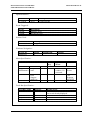
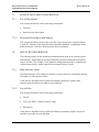
PROGRAM LIST
This part should provide a list of program specifications contained in the program
manual. The program specifications may be grouped under different function
groups.
For example,
5.
PROGRAM LIST
A. Online Input
Program ID
SSMPROJ
SSMSTFF
Description
Support Project Maintenance
Support Staff Maintenance
B. Reports & Enquiry
Program ID
SSLPROJ
SSLSTFF
Description
Support Project List
Support Staff List
C. Batch Processing
Program ID
SSMPURG
Description
Purge outdated information
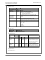
or, the program list may be sorted in alphabetical order
5.
PROGRAM LIST
Program ID
SSLPROJ
SSLSTFF
SSMPROJ
SSMPURG
SSMSTFF
Description
Support Project List
Support Staff List
Support Project Maintenance
Purge outdated information
Support Staff Maintenance
6-3
DOCUMENTATION STANDARDS
FOR IMPLEMENTATION PHASE
6.4
PROGRAM MANUAL
PROGRAM SPECIFICATIONS
Each program specification should include the information as described below.
6.4.1
Program ID
This is the unique identification assigned to a program unit. If the code is
structured, i.e. certain digit has a special meaning, this should be documented in the
“Definitions & Conventions” of the program manual.
6.4.2
Mode
This describes the operation mode of the program unit. It may be any one of the
following :
6.4.3
Online/Update
Batch/Update
Batch/Report
Online/Enquiry
Online submit batch job
Sub-routine
Program Name
A meaningful program name should be given for each program.
6.4.4
Description
This is a narrative description of the tasks to be performed by the program.
6.4.5
Programming Environment
This includes :
Program Source Filename
Programming Language in use
Version of Compiler/development tools (if the program is auto-generated, the
program generation tool information should be specified here)
Program size and run time main memory requirement (if critical)
6-4
DOCUMENTATION STANDARDS
FOR IMPLEMENTATION PHASE
6.4.6
PROGRAM MANUAL
Amendment History
This describes the amendment made to the program specification. All changes
made to the program specification must be documented.
6.4.7
File Usage
Following information are needed :
Full name of the file/table in use
File Usage (Read, Write, Update, Delete, File Delete, File Create, etc.)
For Client/Server application, the File Location (Database Server, Application
Server, Client, etc.) and the way of accessing the file/table (e.g. using remote
procedure call) should be documented.
6.4.8
Input Parameters
This describes the format of the parameters used as input to the program. If the
program is a subroutine, a separate paragraph on the output parameters/ messages
returned should also be given.
6.4.9
Screens Used
This is a list of all screen/window identifier involved. The screen layouts are
placed in the Screen/Report Section of the Data Manual.
6.4.10 Processing Logic
This provides a narrative description on the processing steps. Sufficient details
should be given for the programmers to complete coding and testing of the
program. The followings should be elaborated where applicable :
Normal start
Special restart
Program options
Validity check
Screen/Window Navigation
Editing criteria
6-5
DOCUMENTATION STANDARDS
FOR IMPLEMENTATION PHASE
PROGRAM MANUAL
Arithmetic computation and logical manipulation
End procedures
Events and the corresponding actions (including control break for reports)
Message displayed
Tabular form and decision table should be used if appropriate.
6.4.11 External Reference
This describes any library procedure (subroutine) called within the program.
These include special-purpose procedures written for the applications, in-house
library procedures and software library procedures supplied by the manufacturers
but exclude calls generated by the compiler system.
Procedure/Function/Routine ID
Library filename
Input/Output Parameters
Remarks
For client/server situation, the location of remote procedure should be documented
in Remarks.
6.4.12 Program Limits
This describes areas where the capability of the program is likely to be limited by
design, including :
sequence of input data
volume restriction
storage limitation
limitation on utility program usage
maximum in-store arrays
others
6-6
DOCUMENTATION STANDARDS
FOR IMPLEMENTATION PHASE
PROGRAM MANUAL
6.4.13 Unit Test Record
For each unit test performed on the program, the following should be given :
Test number
Test Description
Expected/Actual Result
Test data generating procedures (if applicable)
Test run procedures (if applicable)
6.4.14 Program Listing
The latest version of all the programs should be kept in softcopy for future
reference and maintenance. Depending on the development environment, project
team should decide whether hardcopy of the program source are included in the
Program Manual.
6-7
DOCUMENTATION STANDARDS
FOR IMPLEMENTATION PHASE
PROGRAM MANUAL
6.5
ILLUSTRATION
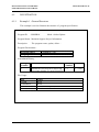
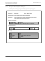
6.5.1
Example 1 : General Structure
This example is used to illustrate the structure of program specification.
Program ID
: SSMPROJ
Mode : Online/Update
Program Name : Maintain Support Project Information
Description
: The program create, update, delete ...
Program Environment :
Program Source
Language/
SSMPROJ.COB
COBOL
Amendment History :
Change
Number
1
Revision Description
Amend the screen layout to add a flag
represents whether it is an ASA project.
Revision
Number
1.1
Date
5.7.1995
File Usage :
File
TEAM
USERDEPT
PROJECT
Usage
Read
Read
Read, Write, Update, Delete
6-8
DOCUMENTATION STANDARDS
FOR IMPLEMENTATION PHASE
PROGRAM MANUAL
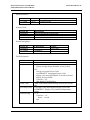
Input Parameters :
Parameter
G_USER
Format
X(12)
Description
Login User ID
Screens Used :
Screen ID
SSMPROJ
LUTEAM
Description
Project Maintenance Main Input
Team Master Look Up
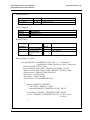
Screen Navigation :
Screen ID
SSMPROJ
LUTEAM
Called from
Calling
LUTEAM
SSMPROJ
Field Navigation :
Field
Action
Project Code
Team Code
User Dept Code
Confirm Flag
Validation/Action
Only allow “A”, “D”, “U” values.
if Action = “A”
System Assign unique identifier in 9(9) format
else
Accept user input Project Code
read PROJECT using input Project Code
display error message ER0001 if record not found
display Project Details
if Action = “D”
skip input to Confirm Flag.
Team Code entered must already exist in the TEAM
file.
User Dept Code entered must already exist in the
USERDEPT. Display UD_NAME as Department
Name.
if “Y”
if Action = “A”
Insert ... record
else
....
6-9
DOCUMENTATION STANDARDS
FOR IMPLEMENTATION PHASE
PROGRAM MANUAL
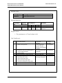
Message Used :
Message ID
ERR0001
Message Text
Project does not exist
External Reference :
Procedure
ID
proc_chkdate
Library
Filename
commlib
Parameters
I/O Name
I
i_date
O
status
Remarks
format
9(6)
X(1)
Commonly used subfunction
Program Limits :
1. The maximum no. of Team Lookup is 999.
...
Unit Test Record :
No
Test Description
1
Create a new project
2
Amend the newly created project
- project start/end date
- project name
Delete the newly created project
Error Handling
- Invalid action value
- Non-exist team code
- Non-exist user dept code
- Invalid confirmation flag value
3
4
Expected
Results
Auto-generated
project ID and
project successfully
created
All fields amended
correctly
Actual
Results
as expected
Project deleted
Correct error
message displayed
as expected
as expected
as expected
6-10
DOCUMENTATION STANDARDS
FOR IMPLEMENTATION PHASE
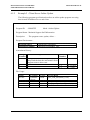
6.5.2
PROGRAM MANUAL
Example 2 : Client/Server Online Update
The following program specification describes an online update program accessing
data located in Database Server and client.
Program ID
: SSMSTFF
Mode : Online/Update
Program Name : Maintain Support Staff Information
Description
: The program create, update, delete ...
Program Environment :
Program Source
Language/Compiler
ssmstff.frm, ssmstff.bas
Microsoft Visual Basic V4.0
Amendment History :
Change
Number
1
2
3
Revision Description
Revision
Number
1.1
Change the table structure of STAFF to
keep track the date the staff transfer from
support team to other team.
...
1.2
1.3
Date
1.7.1994
8.12.1994
5.7.1995
File Usage :
Table
STAFF
TEAM
Location
Database
Server
Client
Usage
Read
Access Mean
proc_read_staff(Staff_Code)
Insert
Update
Read
proc_insert_staff(Staff_Code, ...)
proc_update_staff(Staff_Code, ...)
-
6-11
DOCUMENTATION STANDARDS
FOR IMPLEMENTATION PHASE
PROGRAM MANUAL
Input Parameters :
Parameter
G_USER
Format
X(12)
Description
Login User ID
Event Triggered :
Event
-11000
-12000
Description
Database Error
Divided by Zero
Screens Used :
Screen ID
SSMSTFF
Description
Support Staff Maintenance Main Input
Windows Navigation :
Screen ID
SSMSTFF
Modal
Y
Called from
Calling
Menu Specification :
Menu Item
Fast
Key
Level 1
Level 2
Support Staff Add new
Maintenance staff
Level 3
Nil
Alt-SP
Print
Support
Staff List
Disable
When
Action
When
window 1 is
activated
Clear
Screen
Call
Program
SSLSTFF
Tools Bar Specification :
Tool Bar Name
Previous Record
Fast Key
Alt-P
Next Record
Help
Alt-N
Alt-F1
Disable when
No Record retrieved.
1st record already displayed
...
Enabled at all time
6-12
DOCUMENTATION STANDARDS
FOR IMPLEMENTATION PHASE
PROGRAM MANUAL
Window Event :
Screen Objects
Event
For Window SSMSTFF :
Window
Startup
Staff Code
Input
Development
Experience
(check box)
Check
Scan Button
Confirm Button
Action
Reset ...
Staff Code must be numeric
call proc_read_staff(Staff_Code)
returning Staff Details
If Staff Code already existed in File ABC ...
Enable the input of Development Experience
field.
Un-check Set Development Experience to Nil.
Disable the input of Development Experience.
Click
call proc_scan_photo
Click
Retrieve ...
if ... then
...
endif.
Update ...
Message Used :
Message ID
ERR0001
Message Text
Project does not exist
External Reference :
Procedure
ID
proc_read
_staff
proc_scan
_photo
Library
Parameters
Filename
I/O Name
commlib I
codes
O
status
scanlib
O
Remarks
format
9(12)
X(1)
...
bitmap Large
Binary
Object
Remote Procedure Call locate in Database Server.
Activate event -11000 if
server not available.
Procedure supplied by the
scanner vendor. Refer to
XXX document for details
Program Limits : ...
Unit Test Record : ...
6-13
DOCUMENTATION STANDARDS
FOR IMPLEMENTATION PHASE
6.5.3
PROGRAM MANUAL
Example 3 : Batch Update and Report
A batch update and report program called by a parameter input program.
Program ID
: SSMPURG
Mode : Batch/Update
Program Name : Purge outdated project support information.
Description
: Purge outdated project support information and print a detail
report showing the purged project history.
Program Environment :
Program Source
Language / Compiler
ssmpurg.c
ANSI C with Oracle Pro*C pre-compiler
Amendment History :
Change
Number
Revision Description
Revision
Number
Date
File Usage :
Table
STAFF
TEMPTABLE
PROJECT
TEAM
Usage
Read
Table Create, Insert, Table Drop
Read, Delete
Read
6-14
DOCUMENTATION STANDARDS
FOR IMPLEMENTATION PHASE
PROGRAM MANUAL
Input Parameters :
Parameter
G_USER
Format
X(12)
Description
Login User ID
Event Triggered :
Event
-11000
-12000
Description
Database Error
Divided by Zero
Report Groups :
Sorting
Sequence
1
2
3
Data Items
Project End Date
Project Code
Project Event
Date
Control
Break
1
2
Remarks
Page Break
Retrieval Logic for report:
For each PROJECT with PROJECT.STATUS = “C” {Completed}
and PROJECT.END_DATE on or after 1 year before
ordered by END_DATE, CODE
Retrieve STAFF with CODE = PROJECT.SUPPORT_STAFF
Retrieve TEAM with TEAM.CODE = PROJECT.TEAM_CODE
(Project Name = PROJECT.DESCRIPTION
Staff Code = STAFF.CODE
Staff Name = STAFF.NAME
Project Team = TEAM.DESCRIPTION
...
)
Retrieve PROJECT_HISTORY
with CODE = PROJECT.CODE
ordered by PROJECT_HISTORY.EVENT_DATE
(Event Date = PROJECT_HISTORY.EVENT_DATE
Event = if PROJECT_HISTORY.EVENT is “S” then “Start”
“A” then ...
...
)
6-15
DOCUMENTATION STANDARDS
FOR IMPLEMENTATION PHASE
PROGRAM MANUAL
Processing Logic for Purging :
For all PROJECT records with END_DATE on or before 2 years
delete PROJECT_HISTORY
with PROJECT_HISTORY.PROJECT_CODE = PROJECT.CODE
delete PROJECT record
....
Program Limits : ...
Unit Test Record : ...
6-16
DOCUMENTATION STANDARDS
FOR IMPLEMENTATION PHASE
7.
DATA MANUAL
7.1
PURPOSE
DATA MANUAL
The Data Manual documents all computer data captured, processed or produced
by the system. The various forms of data to be described in the manual include :
*
Source Document
Source Document involved in the system for data input purpose.
Data file
Data which are kept in the system for future processing. These can be
conventional structured file or database.
Screen/Report
All Screens/Reports or documents which are output on printer, external media
or video display terminal.
Some development environments are capable of generating most of the
information required in the Data Manual. Project Teams are recommended to
make the best of the document generating features of the tools, so as to save the
effort required in preparing and updating the document.
If none of the above forms of data is designed for the application system (e.g. in
the setting up of a pure LAN), the preparation of Data Manual will not be
required.
7-1
DOCUMENTATION STANDARDS
FOR IMPLEMENTATION PHASE
7.2
DATA MANUAL
TABLE OF CONTENTS
TABLE OF CONTENTS
1
PURPOSE
2
SCOPE
3
REFERENCES
4
DEFINITIONS AND CONVENTIONS
5
5.1
5.2
5.2.1
5.2.2
5.2.3
SOURCE DOCUMENT DESCRIPTION
List of Documents
Document Description and Sample
[Document ID #1]
[Document ID #2]
....
6
6.1
6.2
6.3
6.3.1
6.3.2
6.3.3
DATA FILE DESCRIPTION
Data Structure Chart
List of Files
File/Table Description
[File ID/View ID #1]
[File ID/View ID #2]
....
7
7.1
7.2
7.2.1
7.2.2
SCREEN/REPORT DESCRIPTION
List of Screens
Screen Layout
[Screen #1]
[Screen #2]
...
List of Reports
Report Layout
[Report #1]
[Report #2]
7.3
7.4
7.4.1
7.4.2
.
7-2
DOCUMENTATION STANDARDS
FOR IMPLEMENTATION PHASE
DATA MANUAL
In case the data is distributed across different machines, the DATA FILE
DESCRIPTION should be grouped under different platforms as illustrated below :
6
6.1
6.2
6.3
6.3.1
6.3.2
6.3.3
DATA FILE DESCRIPTION - DATABASE SERVER
Data Structure Chart
List of Files
File/Table Description
[File ID/View ID #1]
[File ID/View ID #2]
....
7
7.1
7.2
7.3
7.3.1
7.3.2
7.3.3
DATA FILE DESCRIPTION - APPLICATION SERVER
Data Structure Chart
List of Files
File/Table Description
[File ID/View ID #1]
[File ID/View ID #2]
....
7-3
DOCUMENTATION STANDARDS
FOR IMPLEMENTATION PHASE
7.3
SOURCE DOCUMENT DESCRIPTION
7.3.1
List of Documents
DATA MANUAL
This section should list out the following information :
7.3.2
Form No.
Purpose/Form Description
Document Description and Sample
This section should briefly describe when the source document is used and what it
is used for. Sample of the input document should be attached. In additional to the
blank document, “filled-in” document may also be included.
7.4
DATA FILE DESCRIPTION
The following items are the minimum information that needs to be included in the
Data Manual. Depending on the implementation platform, additional information
may be needed. For example, some database management provides constraint rule
reinforcement facility, which should be documented in this section.
7.4.1
Data Structure Chart
The Data Structure Chart (database schema) is used to show the relationship among
files/tables or other groups of data.
If the data are distributed across different hardware platforms, separate data
structure chart should be provided for each platform.
7.4.2
List of Files
This section should list out the following information :
File ID
Type (E.g. DB2, VSAM or Oracle Table)
Description
If the data are distributed across different hardware platforms, separate list of file
should be provided for each platform.
7-4
DOCUMENTATION STANDARDS
FOR IMPLEMENTATION PHASE
7.4.3
DATA MANUAL
File/Table Description
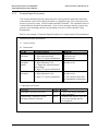
File Description
This sub-section should describe the detailed information of the data file/table,
including file/table physical name, narrative description and other
implementation related information (e.g. tablespace assigned, segment,
blocking factor, etc.).
In case the file contains multiple record types, description for each record type
should be provided.
Any data replication information should also be documented here. For
example, if File A is an image (or extracted summary) of File B as at last
month end, this relationship needs to be documented in both File Description
of File A and File B. Noted that File A and File B may locate in same
machine, or in different machines in distributed data cases.
Record Description
This sub-section should list out the record structure, including field/column
name, description, size and format (stored and display), etc.
If there are multiple record types for a data file, or REDEFINE clause is used,
there should be multiple record description for the data file.
Index Description
This sub-section can be omitted if the index are embedded in the data file and
documented in the Record/Row Description.
For each index of the corresponding data file/table, the field/column involved
and their sequence (Ascending or Descending) should be specified. If any
environment specific facility is applied, for example, cluster index or bit map
index, the information should also been documented.
7-5
DOCUMENTATION STANDARDS
FOR IMPLEMENTATION PHASE
DATA MANUAL
For example : The Table/Row/Index Description for Oracle RDBMS table
A_CODE
6.3.1
A_CODE
6.3.1.1
File Description
A_CODE contains ...... information.
tablespace for data: user_table_space1
tablespace for index A_CODE_IND1 : user_index_space1
...
6.3.1.2
6.3.1.3
Record Description
Column
Description
Attribute
Size
A_CODE
A_DESC
A_PCT
A code
A description
A percentage
varchar2
varchar2
number
5
30
4,2
Output
Format
XXX-XX
X(30)
9999.99%
Null ?
N
Y
N
Index Description
Index
A_CODE__IND1
A__CODE_IND2
Uniqueness
YES
Column
A_CODE
Order
Ascending
NO
A_DESC
A_DESC
Ascending
Descending
Remarks
Cluster
Index
7-6
DOCUMENTATION STANDARDS
FOR IMPLEMENTATION PHASE
DATA MANUAL
For example : The Record Description for Index Sequential File with multiple
record type.
6.3.1
A_MASTER
6.3.1.1
File Description
A_MASTER file contains ...... information.
The Header Record is used to ....
The Tx. Record are used to ...
Blocking Factor : ...
Record Size : ...
(if record size for each record type is different,
the record size will be documented in Record Description)
6.3.1.2
Record Description
6.3.1.2.1
Record Type : Header Record
6.3.1.2.2
Field
Key
Description
Picture
A-CODE
Y
A code
X(5)
REC-TYPE
Y
Record Type
X(1)
FILLER
A-DESC
A-PCT
FILLER
Y
Filler
A description
A percentage
X(6)
X(30)
99V99
X(30)
Output Remarks
Format
XXXXX
X
= “1” for
header record
X(6)
Blank
X(30)
99.99%
X(30)
Record Type : Transaction Record
Field
A-CODE
REC-TYPE
Key
Y
Y
Description
A code
Record Type
Picture
X(5)
X(1)
A-TX-DATE
TX_DTL
Y
Tx Date
Tx Details
9(6)
X(50)
Remarks
= “2” for Tx
Record
in YYMMDD
In the above case, the key is embedded in the data file, and thus the Index Description is
omitted.
7-7
DOCUMENTATION STANDARDS
FOR IMPLEMENTATION PHASE
7.5
SCREEN/REPORT DESCRIPTION
7.5.1
List of Screens
DATA MANUAL
This section should list out all screen ID (and description if applicable) by screen
ID or functional group sequence.
7.5.2
Screen Layout
This section should give a collection of all screen layouts as mentioned in the List
of Screen.
7.5.3
List of Reports
This section should list out all report ID (and description if applicable) by report ID
or functional group sequence.
7.5.4
Report Layout
This section should give a collection of all the Computer Output (reports, preprinted form, etc.) layouts as mentioned in the List of Report.
7-8
DOCUMENTATION STANDARDS
FOR IMPLEMENTATION PHASE
APPLICATION OPERATION MANUAL
8.
APPLICATION OPERATION MANUAL
8.1
PURPOSE
The purpose of the Application Operation Manual (AOM) is to provide relevant
information to the computer operation staff of the system implemented. It should
document in detail the instructions of all the work to be performed by the
computer operation staff in running the application system. The work handled by
end user should be documented in the Application User Manual.
If no additional activity is introduced to the computer operation staff after the
application system is implemented, the preparation of AOM will not be required.
8-1
DOCUMENTATION STANDARDS
FOR IMPLEMENTATION PHASE
8.2
APPLICATION OPERATION MANUAL
TABLE OF CONTENTS
TABLE OF CONTENTS
1
PURPOSE
2
SCOPE
3
REFERENCE
4
DEFINITIONS AND CONVENTIONS
5
5.1
5.2
5.3
5.4
5.5
SYSTEM DESCRIPTION
System Overview
Job Identification/Description
System Flow
Job Run Flow
Summary of Program Description
6
6.1
6.2
SYSTEM MEDIA INPUT AND OUTPUT
Input Tapes/Discs
Output Tapes/Discs
7
7.1
7.2
7.3
7.4
SYSTEM OUTPUT REPORTS
Daily Reports
Weekly Reports
Monthly Reports
Other Reports
8
8.1
8.2
8.3
OPERATIONS DESCRIPTION
On-line Schedule
Batch Schedule
Adhoc Schedule
9
9.1
9.2
RUN JOB SPECIFICATIONS
[Job #1]
[Job #2]
......
8-2
DOCUMENTATION STANDARDS
FOR IMPLEMENTATION PHASE
10
10.1
10.2
10.3
10.3.1
10.3.2
10.4
10.5
APPLICATION OPERATION MANUAL
ERROR HANDLING
Critical Errors Handling
Non-Critical Errors Handling
Other Errors Handling Procedures
Input Tape Error Handling
Error Message Handling
Job Restart Procedure
Contact Points
8-3
DOCUMENTATION STANDARDS
FOR IMPLEMENTATION PHASE
8.3
SYSTEM DESCRIPTION
8.3.1
System Overview
APPLICATION OPERATION MANUAL
This section should briefly describe the major functions provided by the application
system.
8.3.2
Job Identification/Description
This section should describe the naming convention for a job.
8.3.3
System Flow
This section should document the flow of the system in which all programs, input
and output media are shown.
8.3.4
Job Run Flow
This section should describe the sequence for all separate jobs using Job Run Flow
diagram.
8.3.5
Summary of Program Description
This section should provide a brief summary about the job program's description.
8.4
SYSTEM MEDIA INPUT OUTPUT
This part should describe in detail the nature of input and output media.
8.4.1
Input Tapes/Discs
This section should describe the media required for input.
8.4.2
Output Tapes/Discs
This section should describe the media required for output.
8-4
DOCUMENTATION STANDARDS
FOR IMPLEMENTATION PHASE
8.5
APPLICATION OPERATION MANUAL
SYSTEM OUTPUT REPORTS
This part should describe in brief all reports output from the Application System.
The reports are classified as :
8.6
Daily Reports
Weekly Reports
Monthly Reports
Other Reports (For example, such as Microfilm)
OPERATIONS DESCRIPTION
This section should describe the Operation schedule and service hours of the
Application System. The schedule are classified as :
8.7
On-line Schedule
Batch Schedule
Adhoc Schedule
RUN JOB SPECIFICATIONS
This part should describe (by job) the specifications of all jobs processed. It
includes the following information :
Jobname and Job Function
Estimated Run Time
Parameters
Requirement/Limitation
Program Sequence
Restart Procedures
Output Listings
8-5
DOCUMENTATION STANDARDS
FOR IMPLEMENTATION PHASE
8.8
APPLICATION OPERATION MANUAL
ERROR HANDLING
This part should describe the following :
Procedure for handling Job failure and Job restart. Project Team is required to
provide detail and clear cut instruction on this topic.
Example on Job restart Procedure.
Contact Persons for User and Project Team.
8-6
DOCUMENTATION STANDARDS
FOR IMPLEMENTATION PHASE
8.9
APPLICATION OPERATION MANUAL
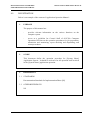
ILLUSTRATION
Below is an example of the content of Application Operation Manual :
1.
PURPOSE
The purpose of this manual are :
2.
-
provides relevant information on the various functions on the
computer system
-
serves as a guideline for Control Staff of OGCIO's Computer
Operations Division on the operation procedures for job preparation,
submission and monitoring; report checking and dispatching; and
restart procedures.
SCOPE
This document define the operation procedure for [System Name]
Application System. It should be reference for all operation staff involved
in the [System Name] application operation.
3.
REFERENCES
3.1
STANDARDS
Documentation Standards for Implementation Phase [S8]
3.2
OTHER REFERENCES
Nil
8-7
DOCUMENTATION STANDARDS
FOR IMPLEMENTATION PHASE
4.
DEFINITIONS AND CONVENTIONS
4.1
DEFINITIONS
APPLICATION OPERATION MANUAL
Nil
4.2
CONVENTIONS
Nil
5.
SYSTEM DESCRIPTION
5.1
SYSTEM OVERVIEW
The [System Name] performs the major function on
...................................
It was an integrated system of the following sub-systems :
Driving Offence Points Record Processing
Drivers Licensing
[Sub-system #3]
[Sub-system #4]
5.1.1 Driving Offence Points Record Processing
The explanation on functions performed by sub-system.
5.1.2 Drivers Licensing
The explanation on functions performed by sub-system.
5.1.3 [Sub-system #3]
..............................................
..............................................
8-8
DOCUMENTATION STANDARDS
FOR IMPLEMENTATION PHASE
5.2
APPLICATION OPERATION MANUAL
JOB IDENTIFICATION/DESCRIPTION
PXXZZZnn is the Job Name where :
P
=
Production job
XX =
Job Identification of [System Name]
ZZZ =
Jobname/Nature of the Job.
UPT
SRT
MRG
PRT
HKP
ADC
nn
=
=
=
=
=
=
=
Update
Sort
Merge
Print
Housekeeping
Adhoc
The assigned Job number 01, 02 ... 99 etc.
8-9
DOCUMENTATION STANDARDS
FOR IMPLEMENTATION PHASE
APPLICATION OPERATION MANUAL
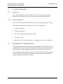
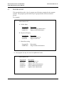
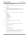
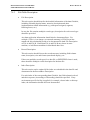
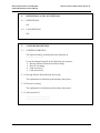
5.3 SYSTEM FLOW
5.3.1 [Sub-system #1] System Flow
IN D E X
F IL E
MO NTHL Y
S T A T IS T I C
S Y S TE M
C O N T R O L F IL E
P RG M 1000
P R IN T A N D A R C H IV E
P U B L IC L O G
P U B L IC
LOG
D A IL Y P U B L IC
L O G CO NTRO L
REPORT
D A IL Y
P U B L IC L O G
ID C A M S
M E R G E P U B L IC L O G
ME RG E D
P U B L IC L O G
ID C A M S
D E L E T E T E M P /S K U P
F IL E
ID C A M S
RENAME
M E R G E D F IL E T O
A R C H IV E F I L E
N E W A R C H IV E
P U B L IC L O G
5.3.2 ..........
8-10
DOCUMENTATION STANDARDS
FOR IMPLEMENTATION PHASE
APPLICATION OPERATION MANUAL
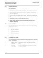
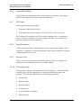
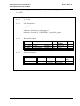
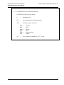
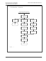
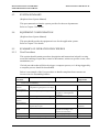
5.4 JOB RUN FLOW
5.4.1 Job Run Flow -- Daily Job
Run after CICS service close down
PXXZZZnn
PXXZZZ01
PXXZZZ02
PXXZZZ04
PXXZZZ03
PXXZZZ05
END
PXXZZZ06
PXXZZZ07
PXXZZZ08
PXXZZZ09
END
8-11
DOCUMENTATION STANDARDS
FOR IMPLEMENTATION PHASE
APPLICATION OPERATION MANUAL
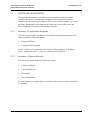
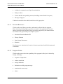
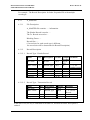
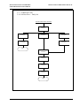
5.4.2 Job Run Flow -- Weekly Job
Run after CICS service close down
Run after completion of all DAILY JOBS
PXXZZZ10
PXXZZZ11
PXXZZZ12
PXXZZZ13
END
PXXZZZ14
PXXZZZ15
PXXZZZ16
PXXZZZ17
PXXZZZ18
PXXZZZ19
PXXZZZ20
PXXZZZ21
END
5.4.3 ..........
8-12
DOCUMENTATION STANDARDS
FOR IMPLEMENTATION PHASE
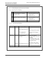
5.5
SUMMARY OF PROGRAM DESCRIPTION
Jobname
PXXUPTnn
PXXZZZnn
6.
6.1
APPLICATION OPERATION MANUAL
Program ID
PRGM1000
PRGM2000
PRGM3000
PRGM4000
Program Description
Update payment transaction
Generate daily payment report
Cancel Account
......
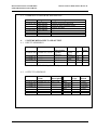
SYSTEMS MEDIA INPUT AND OUTPUT
INPUT TAPES/DISCS
Jobname
Data Set Name
PXXUPTnn
XXXXX.YYY.ZZ
PXXSRTnn
PXXPRTnn
..........
..........
File
Description
Update
Enquiry
..........
..........
Medium
Freq No. of
Copy
D
1
Open
Reel
Cartridge W
Disc
M
4
3
Note : D= Daily, W= Weekly, M= Monthly
6.2
OUTPUT TAPES/DISCS
Jobname
PXXUPTnn
PXXSRTnn
PXXPRTnn
Data Set
Name
XXXXX.YYY
..........
..........
File
Description
File Code
..........
..........
Medium
No. of
Copy
Disc
7
Cartridge 2
Cartridge 3
Disc
Retention
Period
7 Days
2 Weeks
3 Months
3 Days
8-13
DOCUMENTATION STANDARDS
FOR IMPLEMENTATION PHASE
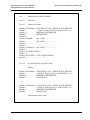
7.
7.1
APPLICATION OPERATION MANUAL
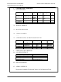
SYSTEM OUTPUT REPORTS
DAILY REPORTS
Jobname
Report ID
PXXUPTnn
[Report ID #1]
[Report ID #2]
PXXPRTnn
..........
Report
Name
Update
Report
Daily
Checklist
..........
Media
In Use
S1P
Decollating No. of
Yes/No
Copy
No
3
S1P
No
7.2
WEEKLY REPORTS
..........
7.3
MONTHLY REPORTS
..........
7.4
YEARLY REPORTS
..........
7.5
OTHER REPORTS - MICROFILM/MICROFICHE
Jobname
PXXUPTnn
PXXPRTnn
8.
8.1
File ID/ File
Description
[File ID #1]
[File ID #2]
..........
Microfiche
Master / Copy
1
1
1
2
..........
2
Rollfilm
Freq.
1
1
Weekly
Monthly
OPERATION DESCRIPTION
ON-LINE SCHEDULE
Monday through Friday
Saturday
Sunday
Public Holidays
8.2
BATCH SCHEDULE
..........
8.3
ADHOC SCHEDULE
0800 - 1800
0800 - 1300
No on-line service
No on-line service
Request are forwarded to Production Control via Job Submission Form.
8-14
DOCUMENTATION STANDARDS
FOR IMPLEMENTATION PHASE
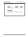
9.
9.1
APPLICATION OPERATION MANUAL
RUN JOB SPECIFICATIONS
PXXZZZnn
9.1.1 Function
-
To merge all I/P Master Records
To sort Master Records
To print Master Record list
9.1.2 Estimate Run Time
15 minutes
9.1.3 Parameters
Nil
9.1.4 Requirement/Limitations
-
Run daily at 18:00 after close of On-line CICS
Cannot run with other batch job
9.1.5 Program Sequence
Step
STEP001
STEP002
STEP003
Program
PRGM1010
PRGM1020
PRGM1030
Highest RC
00
00
00
Function
Merge Master Records
Sort Master Records
Print Record List
9.1.6 Restart Procedure
In case of System error, simply rerun job from Job Step.
Other than System Failure, please refer Chapter 10.
9.1.7 Output Listings
-
Journal
P1030LST - Master Record List
8-15
DOCUMENTATION STANDARDS
FOR IMPLEMENTATION PHASE
10.
APPLICATION OPERATION MANUAL
ERROR HANDLING
Unless otherwise specified in Run Job Specification that it would affect the
on-line service on next day or immediate on-line service, all jobs are
considered non-critical.
Operator would contact Support Staff only if critical job failed again after
carried out normal restart/recovery actions. Usually, it is Data Base updating
job that would affect the on-line service. In case of job failure and recovery
fails due to problem on recovery procedure, Project Team should
update/amend the AOM in the following day.
10.1 CRITICAL ERRORS HANDLING
When a job aborts, refer to Run Job Specifications of the AOM and follow
the procedures to prepare for restart or recovery. If a critical job fails to
recover, Production Control Staff is required to contact Support Team of the
Application for advice. Also, to record all information about job failure,
such as time, date and actions performed for further investigation.
10.2 NON-CRITICAL ERROR HANDLING
All jobs are considered non-critical unless otherwise specified. All noncritical jobs should have their own recovery procedure. Step by step and job
by job. If the procedure does not work and cause failure on job recovery,
Production Control staff should follow up the case to inform Support Team
to amend/update the AOM as soon as possible.
8-16
DOCUMENTATION STANDARDS
FOR IMPLEMENTATION PHASE
APPLICATION OPERATION MANUAL
10.3 OTHER ERRORS HANDLING PROCEDURES
10.3.1 Input Tape Error Handling
1
Error
Error in DUMMY or VOLSER
parameter values
Action
1. Verify the parameter values
2. Correct errors
3. Resubmit the job
2
Duplicate Volume Serial Numbers
1. Verify the parameter values
2. Correct errors
3. Resubmit the job
3
10.3.2
Error Message Handling
Jobname Program
Message
Action
PXXZZZ01 PXX001 E010:Invalid Control File Check the file content
E020:Empty System File
Check System File content
PXXZZZ02
PXX002
PXX003
E030, E035-E038:
SQL Error
Contact OGCIO Support
ASAP
E020:Records not
matched
Check I/P Parameter.
If typing mistake, rerun from
beginning
If not typing mistake, contact
User for correct I/P Parameter
during office hours.
Information only. Inform
E030:Subscriber not exist Project team during office
hours
8-17
DOCUMENTATION STANDARDS
FOR IMPLEMENTATION PHASE
APPLICATION OPERATION MANUAL
10.4
JOB RESTART PROCEDURE
10.4.1
PXXX001
10.4.1.1
Normal Job Steps
000001 //PXXX0001 JOB (PXXX,YYYY), 'PRINT DAILY REPORT',
000002 //
CLASS=P, MSGCLASS=X, MSGLEVEL=(1,1),
000003 //*
RESTART=XXXXXXXX,
000004 //
REGION=8M
000005 //*
000006 //JOBLIB
DD DSN=...........................
000007 //
DD DSN=...........................
000008 //
....................................
000009 //
....................................
000010 //JOBPROC* DD DSN=...........................
000011 //*
000012 //* DELETE FILES
000013 //*
000014 //DELSTEP1 EXEC PGM=IEFBR14
000015 //.............................................
10.4.1.2
If job aborted on step 'DELSTEP1'
Replace
000001 //PXXX0001
000002 //
000003 //*
000004 //
JOB (PXXX,YYYY), 'PRINT DAILY REPORT',
CLASS=P, MSGCLASS=X, MSGLEVEL=(1,1),
RESTART=XXXXXXXX,
REGION=8M
to
000001 //PXXX0001
000002 //
000003 //
000004 //
JOB (PXXX,YYYY), 'PRINT DAILY REPORT',
CLASS=P, MSGCLASS=X, MSGLEVEL=(1,1),
RESTART=XXXXXXXX,
REGION=8M
Then submit job for rerun.
8-18
DOCUMENTATION STANDARDS
FOR IMPLEMENTATION PHASE
APPLICATION OPERATION MANUAL
10.5 CONTACT POINTS
User Support
Office Hours
(0845-1730)
Other Hours
1st line - [Support Staff #1]
2nd line - [Support Staff #2]
[Phone No. #1]
[Phone No. #2]
[Pager #1]
[Pager #2]
[Phone No. #3]
[Phone No. #4]
[Pager #3]
[Pager #4]
Maintenance Support
1st line - [Support Staff #3]
2nd line - [Support Staff #4]
8-19
DOCUMENTATION STANDARDS
FOR IMPLEMENTATION PHASE
9.
APPLICATION USER MANUAL
9.1
PURPOSE
APPLICATION USER MANUAL
The purpose of the Application User Manual is to provide relevant information to the
user department of the system implemented. The intended users of the manual are the
staff of the user department who will use the system.
The manual should contain detailed instructions in addition to an overall description of
the procedures. The detailed instructions should be made up of a set of standard
instructions, each part being complete in itself describing a logically distinct function
(e.g. procedures relating to a particular transactions). The idea is that copies of different
parts would be distributed to different persons whose duties are to carry out the
particular work. In other words, the standard instructions would be able to form part of
the job description of a post.
If the application provides online facilities for the user, a part on the terminal operating
procedures should also be documented.
Normally, it is the user responsibility to prepare the Application User Manual. Project
team should provide adequate assistance to the user in preparing the manual.
9-1
DOCUMENTATION STANDARDS
FOR IMPLEMENTATION PHASE
9.2
APPLICATION USER MANUAL
TABLE OF CONTENTS
TABLE OF CONTENTS
1
PURPOSE
2
SCOPE
3
REFERENCES
4
DEFINITIONS AND CONVENTIONS
5
5.1
5.2
SYSTEM SUMMARY
Objectives
System Functions
6
6.1
6.2
6.3
EQUIPMENT CONFIGURATION
Computer Hardware
Ancillary Machinery
Consumable and Media
7
7.1
7.2
SUMMARY OF OPERATION PROCEDURES
User Procedures
Terminal Input Procedures
8
RUN SCHEDULE
9
COMPUTER INPUT DOCUMENTS
10
COMPUTER OUTPUT DOCUMENTS
11
TERMINAL OPERATING INSTRUCTIONS
9-2
DOCUMENTATION STANDARDS
FOR IMPLEMENTATION PHASE
9.3
APPLICATION USER MANUAL
SYSTEM SUMMARY
(Replicate from System Manual)
This part summarizes what the system provides for the user departments.
Refer to Chapter 5 for details.
9.4
EQUIPMENT CONFIGURATION
(Replicate from System Manual)
This part should provide the equipment in use for the application system.
Refer to Chapter 5 for details.
9.5
SUMMARY OF OPERATION PROCEDURES
9.5.1
User Procedures
This section should contain procedures description and instructions in detail covering
areas like batching of input data, control of documents, actions on specific events, error
amendments, etc.
Clerical procedures that will directly trigger a computer process, or is being triggered by
a computer process should be documented.
Below is an example of the User procedure to handle complaint from customer on
incorrect invoice outstanding balance.
Section/
Clerical Procedures
Computer Procedures
User Role
Event : Complaint from customer, the outstanding balance on invoice is incorrect.
Event occurred randomly.
Customer
Report the detail information in
Service
Complaint Log and pass to A/C dept
Representative
A/C Supervisor
Acknowledge complaint log
Perform Customer Ledger
Enquiry to investigate the
situation.
The investigation result was logged.
Customer
Feedback the result to customer
Service
Representative
If manual adjustment is needed,
prepare adj tx input
Computer Input
Perform Adjustment Tx entry
Staff
process according to A/C
supervisor instruction
Print Adj update report
A/C Supervisor
Check the Adj update report
Form/Screen
/Report Ref
Form CL001
Screen SCM013
Form CL001
Form
ADJ010
Screen SCM015
Report SCP040
9-3
DOCUMENTATION STANDARDS
FOR IMPLEMENTATION PHASE
APPLICATION USER MANUAL
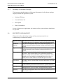
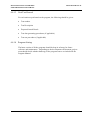
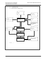
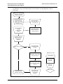
An alternative way to document the User Procedures is using diagram, such as
following :
Receive complaint from
customer : Incorrect
Invoice Balance
Customer Service
Representative:
Report the detail
information in the
complaint log
A/C Supervisor :
Acknowledge the
complaint log
A/C Supervisor:
Log the
Investigation
Result
A/C Supervisor:
Perform Customer
Ledger Enqiury
Customer Service
Representative :
Feedback to
customer
If A/C Adj is needed
YES
A/C Supervisor:
Prepare A/C adj
tx input
Symbol in use:
Computer Input Staff:
Input A/C adj tx
Computer
Process
NO
Computer Input Staff:
Print A/C Adj Update
Report
Complaint from
customer handled
Terminator
A/C Supervisor:
Check the A/C
Adj Update
Report
Manual
process
Decision
9-4
DOCUMENTATION STANDARDS
FOR IMPLEMENTATION PHASE
9.5.2
APPLICATION USER MANUAL
Terminal Input Procedures
This section should specify the instructions for carrying out the application functions
(transactions) via the video display terminal covering data entry, error corrections and
actions on specific events. Screen formats should be included. The validation rules for
critical data item should be documented. A list of error messages that the system may
generate, their meanings and the corresponding corrective actions should be fully
documented.
Below is an example of Terminal Input Procedures of a simple master file maintenance.
Maintain Salesman Information
A. Screen Layout
....
B. Instructions
To Do
Add a new
salesman
Change
salesman
details
Delete a
salesman
Action Required
1. Input “A” in Action
2. Input salesman detail
3. Input “Y” upon confirmation.
1. Input “U” in Action
2. Input Salesman Code
3. Change the Salesman details
accordingly.
4. Input “Y” upon confirmation.
1. Input “D in Action
2. Input Salesman Code
3. Input “Y” upon confirmation.
Remarks
1. System will generate the
salesman code
automatically.
1. The salesman must
already exists.
1. The salesman must
already exists.
2. The salesman must have
no outstanding commission.
...
C. Messages and Action
Messages
Salesman Code does not exists
Nature
Error
Outstanding Commission exists,
salesman cannot be deleted
Error
Action
Check if the wrong salesman
code is inputted.
Withhold the deletion. Pass the
case to accounting dept for
investigation....
9-5
DOCUMENTATION STANDARDS
FOR IMPLEMENTATION PHASE
9.6
APPLICATION USER MANUAL
RUN SCHEDULE
This part should provide detailed schedule for each periodic and ad hoc job to be
triggered by users. Those processes handled by Computer Operation Staff can be
omitted here. Information provided should include :
9.7
Event
Scheduled date/time
Jobs/macros used (if any)
Estimated run time
COMPUTER INPUT DOCUMENTS
This part should provide detailed instructions for the preparation of computer input
documents. A completed sample of each document should be given.
9.8
Document-id
Purpose
When used
Fill in instructions
COMPUTER OUTPUT DOCUMENTS
This part should describe all output documents produced by the system and detailed
instructions on the checking of such documents. A completed sample of each output
documents should be given.
Printout-id
Purpose
No. of copies
Filing instructions
Checking instructions
Messages displayed
Meaning and action
9-6
DOCUMENTATION STANDARDS
FOR IMPLEMENTATION PHASE
9.9
APPLICATION USER MANUAL
TERMINAL OPERATING INSTRUCTIONS
This part should describe in detail steps and instructions in operating terminal. It should
cover :
Power on/off of the Terminal
Signing on/off
Meaning of function keys
Preliminary fault diagnosis checking (lamps setting, modems)
Fault reporting
9-7
DOCUMENTATION STANDARDS
FOR IMPLEMENTATION PHASE
COMPUTER OPERATING
PROCEDURES MANUAL
10.
COMPUTER OPERATING PROCEDURES MANUAL
10.1
PURPOSE
The Computer Operating Procedures Manual provides information and operating
instructions related to the operating of the computer system. The intended users
are the operating staff of the computer operation department.
This manual should be site-specific. For established computer site with this
manual already prepared, there is no need to re-produce it for individual system
introduced into the site. However, please note that some parts of the manual, for
example the Hardware Configuration or the System Files section, may need to be
updated due to the introduction of new system.
It should be noted that the manual is not intended to be a complete replacement of
the formal technical publication as issued by the manufacturer. Information and
instructions documented in the manual would be specific to the installation and
should take precedence over the manufacturer's counterparts.
When the system is to be operated by the end users themselves, the detailed
procedures would be explained in the Application User Manual instead.
10-1
DOCUMENTATION STANDARDS
FOR IMPLEMENTATION PHASE
10.2
COMPUTER OPERATING
PROCEDURES MANUAL
TABLE OF CONTENTS
TABLE OF CONTENTS
1
PURPOSE
2
SCOPE
3
REFERENCES
4
DEFINITIONS AND CONVENTIONS
5
5.1
5.1.1
5.1.2
5.2
5.3
5.4
COMPUTER SYSTEM INFORMATION
Hardware Configuration
Computer Hardware Configuration
Communication Network Configuration
Hardware Components Description
System Software Environment
Systems Files
6
COMPUTER SYSTEM OPERATING PROCEDURES – NORMAL
CASE
Powering On/Off
Switching On/Off The Hardware Components
Loading/Closing Down the Computer System/Communication Network
Media Placement
Scheduling & Spooling
System Prompts/Exceptions Handling
6.1
6.2
6.3
6.4
6.5
6.6
7
7.1
7.2
7.3
7.4
COMPUTER SYSTEM OPERATING PROCEDURES –
ABNORMAL CASE
Taking System Dumps
Checking the Air-Conditioning System/Power Supply System
Fault Reporting Procedures
First Line System Crash/Communication Faults Diagnosis
10-2
DOCUMENTATION STANDARDS
FOR IMPLEMENTATION PHASE
COMPUTER OPERATING
PROCEDURES MANUAL
8.1
8.2
8.3
COMPUTER SYSTEM OPERATING PROCEDURES – RESTART
CASE
Reloading Procedures
Reconfiguration (Switching of Network)
Degraded Mode Operating Procedures
9
9.1
9.2
9.3
MAGNETIC TAPE HANDLING
Tape Deck Handling
Magnetic Tape Failure Recover/Reporting
Labeling of Magnetic Tapes
10
10.1
10.2
OPERATION HOUSEKEEPING JOBS
System Files Backup
Magnetic Media Cleaning
8
10-3
DOCUMENTATION STANDARDS
FOR IMPLEMENTATION PHASE
APPENDIX A
APPENDIX A
CROSS REFERENCE BETWEEN SSADM DELIVERABLES AND THE
CORRESPONDING DOCUMENTS/SECTIONS
Document/Section
SSADM Deliverables
SYSTEM MANUAL
1
Purpose
N/A
2
Scope
N/A
3
References
N/A
4
Definitions and Conventions
N/A
5
System summary
5.1 Objectives
5.2 System functions
N/A
Function Definition
6
Equipment configuration
6.1 Computer hardware
6.2 Ancillary machine
6.3 Consumable and media
7
Software Inventories
7.1 Inventory of application programs
7.2 Inventory of system software
7.3 Inventory of software package
) Selected Technical System
) Option
)
)
Process Module
) Selected Technical System
Option
)
8
Security and backup
Audit, Control and Security
Requirements
9
Database administration
N/A
10 System constraints and limitations
Constraints List
11 Function point analysis
Function Point Analysis
A-1
DOCUMENTATION STANDARDS
FOR IMPLEMENTATION PHASE
Document/Section
APPENDIX A
SSADM Deliverables
PROGRAM MANUAL
1
Purpose
N/A
2
Scope
N/A
3
References
N/A
4
Definitions and Conventions
N/A
5
Program List
N/A
6
Program Specifications
Process Module
DATA MANUAL
1
Purpose
N/A
2
Scope
N/A
3
References
N/A
4
Definitions and Conventions
N/A
5
Source document description
N/A
6
Data file description
( Required System LDS
( Required System Entity
Description
7
Screen/Report description
( Screen Layout
( Report Layout
A-2
DOCUMENTATION STANDARDS
FOR IMPLEMENTATION PHASE
Document/Section
APPENDIX A
SSADM Deliverables
APPLICATION OPERATION MANUAL
1
Purpose
N/A
2
Scope
N/A
3
References
N/A
4
Definitions and Conventions
N/A
5
System description
5.1 System overview
5.2
5.3
5.4
5.5
Job identification/description
System flow
Job run flow
Summary of program description
Required System Overview
of Required System Description
N/A
N/A
N/A
Process Module
6
System media input and output
N/A
7
System output reports
N/A
8
Operations description
N/A
9
Run job specification
N/A
10 Error handling
N/A
A-3
DOCUMENTATION STANDARDS
FOR IMPLEMENTATION PHASE
Document/Section
APPENDIX A
SSADM Deliverables
APPLICATION USER MANUAL
1
Purpose
N/A
2
Scope
N/A
3
References
N/A
4
Definitions and Conventions
N/A
5
System summary
5.1 Objectives
5.2 System functions
N/A
Function Definition
6
Equipment configuration
6.1 Computer hardware
6.2 Ancillary machine
6.3 Consumable and media
) Selected Technical System
) Option
)
)
7
Summary of operation procedures
7.1 User procedures
7.2 Terminal input procedures
Required System Description
Screen Layout
8
Run schedule
N/A
9
Computer input documents
N/A
10 Computer output documents
Report Layout
11 Terminal operating instructions
N/A
A-4
DOCUMENTATION STANDARDS
FOR IMPLEMENTATION PHASE
COMPUTER OPERATING
PROCEDURES MANUAL
APPENDIX B
GOA PROJECTS
Due to project characteristics, only three manuals will be produced in GOA Projects as final
documentation for Implementation Phase. The Application User Manual and Computer
Operating Procedures Manual would be used as cook books for daily operation, whereas
System Manual would be treated as the primary reference materials for future system
maintenance. The table of contents of the three manuals are stated in the following pages.
In order to produce the above three manuals during Implementation Phase, the following
SDLC major steps and interim deliverables should be followed and produced :
SDLC
Major Steps
Deliverables
Guidelines /
Techniques
Physical
System
Design
- User requirements and existing configuration
- Vertical Network Requirement Report
- Horizontal Network Requirement Report
- E-mail System Implementation/Migration Proposal
- Site Preparation Requirement Report
- Network Installation Guide
- Router Configuration Proposal
- Master Activity Plan
[G35], [G41],
[G43], [G44],
System
Integration,
Testings &
Installation
- Prepared Site
- Procured Hardware & Software
User
Acceptance
Testing,
Training &
Production
- Quality Assurance, Resilience Test Plan,
Specification and Results
- Trained User
- GCN Connection
- Handover Document
(*)
- Application User Manual
(*)
- Computer Operating Procedures Manual
(*)
- System Manual
(*)
- Computer Systems in Production Use
[S8]
Project
Evaluation
Review
- Project Evaluation Report
[G38]
(*)
Final deliverables of the project
Ref. No. : S8
B-1
DOCUMENTATION STANDARDS
FOR IMPLEMENTATION PHASE
COMPUTER OPERATING
PROCEDURES MANUAL
FOR GOA PROJECTS, THE PROPOSED TABLE OF CONTENTS FOR SYSTEM
MANUAL, APPLICATION USER MANUAL AND COMPUTER OPERATING
PROCEDURES MANUAL ARE AS FOLLOWS :
DOCUMENT/SECTION
GOA Deliverables
SYSTEM MANUAL
1.
PURPOSE
2.
SCOPE
3.
REFERENCES
4.
DEFINITIONS AND CONVENTIONS
5.
SYSTEM SUMMARY
5.1
5.2
OBJECTIVES
SYSTEM FUNCTIONS
6.
EQUIPMENT CONFIGURATION
6.1 COMPUTER HARDWARE
6.2 ANCILLARY MACHINERY
6.3 CONSUMABLE AND MEDIA
7.
N/A
N/A, details are to be included in
Annex A - Resilience Design and
Recovery Procedures
SOFTWARE INVENTORIES
7.1 INVENTORY OF APPLICATION PROGRAMS
7.2 INVENTORY OF SYSTEM SOFTWARE
7.3 INVENTORY OF SOFTWARE PACKAGES
8.
SECURITY AND BACKUP
9.
DATABASE ADMINISTRATION
10.
SYSTEM CONSTRAINTS AND LIMITATIONS
11.
FUNCTION POINT ANALYSIS
N/A
N/A
N/A
ANNEX A - RESILIENCE DESIGN AND RECOVERY
PROCEDURES
Ref. No. : S8
B-2
DOCUMENTATION STANDARDS
FOR IMPLEMENTATION PHASE
DOCUMENT/SECTION
COMPUTER OPERATING
PROCEDURES MANUAL
GOA Deliverables
APPLICATION USER MANUAL
1.
PURPOSE
2.
SCOPE
3.
REFERENCES
4.
DEFINITIONS AND CONVENTIONS
5.
SYSTEM SUMMARY
5.1
5.2
OBJECTIVES
SYSTEM FUNCTIONS
6.
EQUIPMENT CONFIGURATION
6.1
6.2
6.3
COMPUTER HARDWARE
ANCILLARY MACHINERY
CONSUMABLE AND MEDIA
7.
SUMMARY OF OPERATION PROCEDURES
7.1
7.2
USER PROCEDURES
TERMINAL INPUT PROCEDURES
N/A
8.
RUN SCHEDULE
N/A
9.
COMPUTER INPUT DOCUMENTS
N/A
10.
COMPUTER OUTPUT DOCUMENTS
N/A
11.
TERMINAL OPERATING INSTRUCTIONS
N/A
12.
SYSTEM MESSAGE BROADCASTING
13.
DOCUMENTATION
14.
SERVICES AND SUPPORT
Ref. No. : S8
N/A
N/A
B-3
DOCUMENTATION STANDARDS
FOR IMPLEMENTATION PHASE
DOCUMENT/SECTION
COMPUTER OPERATING
PROCEDURES MANUAL
GOA Deliverables
COMPUTER OPERATING PROCEDURES MANUAL
1.
PURPOSE
2.
SCOPE
3.
REFERENCES
4.
DEFINITIONS AND CONVENTIONS
5.
COMPUTER SYSTEM INFORMATION
5.1
5.2
5.3
5.4
HARDWARE CONFIGURATION
HARDWARE COMPONENTS DESCRIPTION
SYSTEM SOFTWARE ENVIRONMENT
SYSTEM FILES
N/A
N/A
N/A
6.
COMPUTER SYSTEM OPERATING - NORMAL
N/A
7.
COMPUTER SYSTEM OPERATING - ABNORMAL
N/A
8.
COMPUTER SYSTEM OPERATING - RESTART TAPE N/A
9.
MAGNETIC HANDLING
9.1
9.2
9.3
TAPE DECK HANDLING
MAGNETIC TAPE FAILURE RECOVER
LABELLING OF MAGNETIC TAPES
10.
OPERATION HOUSEKEEPING JOBS
10.1 SYSTEM FILES BACKUP
10.2 MAGNETIC MEDIA CLEANING
11.
SYSTEM ADMINISTRATION
11.1 LAN ADMINISTRATION
11.2 LAN USER ADMINISTRATION
11.3 OTHER APPLICATIONS ADMINISTRATION
ANNEX A - E-MAIL SYSTEM ADMINISTRATOR GUIDE
Ref. No. : S8
B-4
DOCUMENTATION STANDARDS
FOR IMPLEMENTATION PHASE
APPENDIX C
APPENDIX C
CROSS REFERENCE BETWEEN OOM DELIVERABLES AND THE
CORRESPONDING DOCUMENTS/SECTIONS
Document/Section
OOM Deliverables
SYSTEM MANUAL
1
Purpose
N/A
2
Scope
N/A
3
References
N/A
4
Definitions and Conventions
N/A
5
System summary
5.1 Objectives
5.2 System functions
6
Equipment configuration
6.1 Computer hardware
6.2 Ancillary machine
6.3 Consumable and media
7
Software Inventories
7.1 Inventory of application programs
7.2 Inventory of system software
7.3 Inventory of software package
Objectives of Required System
Description
Use Case Model
) Selected Technical System
) Option
)
)
List of Components and
Classes
) Selected Technical System
Option
)
8
Security and backup
Audit, Control and Security
Requirements
9
Database administration
N/A
10 System constraints and limitations
Constraints List
11 Function point analysis
Function Point Analysis
C-1
DOCUMENTATION STANDARDS
FOR IMPLEMENTATION PHASE
APPENDIX C
Document/Section
OOM Deliverables
PROGRAM MANUAL
1
Purpose
N/A
2
Scope
N/A
3
References
N/A
4
Definitions and Conventions
N/A
5
Program List
N/A
6
Program Specifications
(
(
(
(
(
Use Case Model
Business Rules
Class Model
Object Sequence Diagrams
Component Dependency
Model
DATA MANUAL
1
Purpose
N/A
2
Scope
N/A
3
References
N/A
4
Definitions and Conventions
N/A
5
Source document description
N/A
6
Data file description
( Required System LDS
( Required System Entity
Description
7
Screen/Report description
( Screen Layout
( Report Layout
C-2
DOCUMENTATION STANDARDS
FOR IMPLEMENTATION PHASE
Document/Section
APPENDIX C
OOM Deliverables
APPLICATION OPERATION MANUAL
1
Purpose
N/A
2
Scope
N/A
3
References
N/A
4
Definitions and Conventions
N/A
5
System description
5.1 System overview
5.2
5.3
5.4
5.5
Job identification/description
System flow
Job run flow
Summary of program description
Required System Overview
of Required System Description
N/A
N/A
N/A
N/A
6
System media input and output
N/A
7
System output reports
N/A
8
Operations description
N/A
9
Run job specification
N/A
10 Error handling
N/A
C-3
DOCUMENTATION STANDARDS
FOR IMPLEMENTATION PHASE
Document/Section
APPENDIX C
OOM Deliverables
APPLICATION USER MANUAL
1
Purpose
N/A
2
Scope
N/A
3
References
N/A
4
Definitions and Conventions
N/A
5
System summary
5.1 Objectives
5.2 System functions
Objectives of Required System
Description
Use Case Model
6
Equipment configuration
6.1 Computer hardware
6.2 Ancillary machine
6.3 Consumable and media
) Selected Technical System
) Option
)
)
7
Summary of operation procedures
7.1 User procedures
7.2 Terminal input procedures
Required System Description
Screen Layout
8
Run schedule
N/A
9
Computer input documents
N/A
10 Computer output documents
Report Layout
11 Terminal operating instructions
N/A
C-4