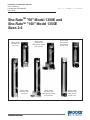
1
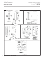
Installation and Operation Manual
X-VA-1350E-eng
Part Number: 541B082AAG
April, 2009
Models 1350E and 1355E
Sho-RateTM "50" Model 1350E and
Sho-RateTM "150" Model 1355E
Sizes 2-6
Model 1350E
Sho-Rate "50"
(no valve)
Model 1355E
Sho-Rate "150"
(no valve)
Model 1350E
Sho-Rate "50"
With optional Integral
flow controller
Model 1355E
Sho-Rate "150"
With optional Integral
flow controller
Model 1350E
Sho-Rate "50"
With optional
needle valve
Model 1355E
Sho-Rate "150"
With optional
needle valve
Models 1350E and 1355E
Installation and Operation Manual
X-VA-1350E-eng
Part Number: 541B082AAG
April, 2009
Essential Instructions
Read this page before proceeding!
Brooks Instrument designs, manufactures and tests its products to meet many national and international standards. Because
these instruments are sophisticated technical products, you must properly install, use and maintain them to ensure they
continue to operate within their normal specifications. The following instructions must be adhered to and integrated into your
safety program when installing, using and maintaining Brooks Products.
• Read all instructions prior to installing, operating and servicing the product. If this instruction manual is not the correct
manual, please see back cover for local sales office contact information. Save this instruction manual for future reference.
• If you do not understand any of the instructions, contact your Brooks Instrument representative for clarification.
• Follow all warnings, cautions and instructions marked on and supplied with the product.
• Inform and educate your personnel in the proper installation, operation and maintenance of the product.
• Install your equipment as specified in the installation instructions of the appropriate instruction manual and per applicable
local and national codes. Connect all products to the proper electrical and pressure sources.
• To ensure proper performance, use qualified personnel to install, operate, update, program and maintain the product.
• When replacement parts are required, ensure that qualified people use replacement parts specified by Brooks Instrument.
Unauthorized parts and procedures can affect the product's performance and place the safe operation of your process at
risk. Look-alike substitutions may result in fire, electrical hazards or improper operation.
• Ensure that all equipment doors are closed and protective covers are in place, except when maintenance is being
performed by qualified persons, to prevent electrical shock and personal injury.
Pressure Equipment Directive (PED)
All pressure equipment with an internal pressure greater than 0.5 bar (g) and a size larger than 25mm or 1" (inch) falls under the
Pressure Equipment Directive (PED). The Directive is applicable within the European Economic Area (EU plus Norway, Iceland
and Liechtenstein). Pressure equipment can be traded freely within this area once the PED has been complied with.
• Section 1 of this manual contains important safety and operating instructions related to the PED directive.
• Meters described in this manual are in compliance with EN directive 97/23/EC module H Conformity Assessment.
• All Brooks Instrument Flowmeters fall under fluid group 1.
• Meters larger than 25mm or 1" (inch) are in compliance with category I, II, III of PED.
• Meters of 25mm or 1" (inch) or smaller are Sound Engineering Practice (SEP).
Installation and Operation Manual
X-VA-1350E-eng
Part Number: 541B082AAG
April, 2009
Models 1350E and 1355E
Dear Customer,
We appreciate this opportunity to service your flow measurement and control requirements with a Brooks
Instrument device. Every day, flow customers all over the world turn to Brooks Instrument for solutions to their
gas and liquid low-flow applications. Brooks provides an array of flow measurement and control products for
various industries from biopharmaceuticals, oil and gas, fuel cell research and chemicals, to medical devices,
analytical instrumentation, semiconductor manufacturing, and more.
The Brooks product you have just received is of the highest quality available, offering superior performance,
reliability and value to the user. It is designed with the ever changing process conditions, accuracy requirements
and hostile process environments in mind to provide you with a lifetime of dependable service.
We recommend that you read this manual in its entirety. Should you require any additional information concerning
Brooks products and services, please contact your local Brooks Sales and Service Office listed on the back cover
of this manual or visit www.BrooksInstrument.com
Yours sincerely,
Brooks Instrument
Installation and Operation Manual
X-VA-1350E-eng
Part Number: 541B082AAG
April, 2009
Models 1350E and 1355E
THIS PAGE WAS
INTENTIONALLY
LEFT BLANK
Installation and Operation Manual
X-VA-1350E-eng
Part Number: 541B082AAG
April, 2009
Contents
Models 1350E and 1355E
Section 1 Introduction
Paragraph
Page
Number
Number
1-1 Description ................................................................................................................................................. 1-1
1-2 Specifications ............................................................................................................................................. 1-1
1-3 Optional Equipment ................................................................................................................................... 1-5
Section 2 Installation
Paragraph
Page
Number
Number
2-1 Receipt of Equipment ................................................................................................................................ 2-1
2-2 Unpacking .................................................................................................................................................. 2-1
2-3 Return Shipment ........................................................................................................................................ 2-2
2-4 Recommended Storage Practice ............................................................................................................... 2-2
2-5 Installation ................................................................................................................................................. 2-3
Section 3 Operation
Paragraph
Page
Number
Number
3-1 Operation ................................................................................................................................................... 3-1
Section 4 Maintenance
Paragraph
Page
Number
Number
4-1 Disassembly & Cleaning ............................................................................................................................ 4-1
4-2 Reassembly procedure .............................................................................................................................. 4-1
Section 5 Parts List
Paragraph
Page
Number
Number
5-1 General ...................................................................................................................................................... 5-1
Figures
Figure
Page
Number
Number
2-1 Typical Flowmeter Installation .................................................................................................................... 2-3
2-2 Dimensions - Sho-Rate 1350E ................................................................................................................... 2-4
2-3 Dimensions - Sho-Rate 1350E and 1355E with Integral Controller ............................................................ 2-5
2-4 Dimensions - Sho-Rate 1355E ................................................................................................................... 2-6
5-1 Parts Drawing Sho-Rate Models 1350E and 1355E .................................................................................. 5-2
Tables
Table
Page
Number
Number
1-1 Capacities for Sho-Rate Model 1350E Rib Guided Tubes, Spherical Floats ............................................. 1-3
1-2 Capacities for Sho-Rate Model 1350E Plain Tapered Tube, Spherical Floats ........................................... 1-3
1-3 Tube and Float Code, Detachable Scale Option, 1st Digit ......................................................................... 1-4
1-4 Tube and Float Code, Detachable Scale Option, 2nd & 3rd Digits ............................................................ 1-4
1-5 Capacities for Sho-Rate Model 1355E Rib Guided Tubes, Spherical Floats ............................................. 1-4
5-1 Parts List - Sho-Rate Models 1350E and 1355E ....................................................................................... 5-3
i
Contents
Installation and Operation Manual
X-VA-1350E-eng
Part Number: 541B082AAG
April, 2009
Models 1350E and 1355E
THIS PAGE WAS
INTENTIONALLY
LEFT BLANK
ii
Section 1 Introduction
Installation and Operation Manual
X-VA-1350E-eng
Part Number: 541B082AAG
April, 2009
Models 1350E and 1355E
1-1 Description
The Sho-Rate Flowmeters are variable area, glass tube, flow rate
indicating meters. The basic elements are a tapered glass metering tube
and a metering float. Features include quick and simple removal or
installation of the tube and float while the meter remains in the process
piping.
1-2 Specifications
Capacities
1350 Series: Refer to Tables 1-1 or 1-2, or 1-3 and 1-4
1355 Series: Refer to Tables 1-3 and 1-4, or 1-5
Accuracy
1350 Series Standard: Accuracy of ±10% of full scale from 100% to 10% of
scale reading
1355 Series Standard: ±5% of full scale from 100% to 10% of scale
reading
Repeatability
0.5% full scale
Rangeability
10 to 1
Pressure
200 psig at temperatures up to 250°F
Pressure Drop
Inquire at factory
Flow Meter Assembly
Pressure Equipment Directive (97/23/EC)
Note: Equipment falls under Sound Engineering Practice (SEP) according
to the
directive.
1-1
Section 1 Introduction
Installation and Operation Manual
X-VA-1350E-eng
Part Number: 541B082AAG
April, 2009
Models 1350E and 1355E
Scales
1350 Series:
Length: 65 mm, nominal
Graduations: Standard: 0-65mm, or 0-100 linear reference scale with air or
water calibration table.
1355 Series:
Length: 150mm, nominal
Graduations: Standard: 0-150 mm, or 0-100 linear reference scale with air
or water calibration table. Optional: for either 65 mm or 150 mm direct
reading scale, ceramic ink fused on glass tube or metal scale plate
mounted beside tube
Type: Standard: Ceramic ink fused on meter tube with contrasting yellow
background
Materials of Construction
Metering Tubes: Borosilicate glass
Floats: Glass, 316 stainless steel, sapphire,
Carboloy®, tantalum
Structural Members:
End fittings: Chrome plated brass, black anodized aluminum, 316
stainless steel
Side Plates:
Standard: Black anodized aluminum
Optional: 316 stainless steel
Window: Clear polycarbonate; Back Window: Milk white polycarbonate
Float Stops:
Standard: Teflon®
Optional: 316 Stainless Steel
Tube Packing:
Standard: Buna-N (Brass and aluminum meters), Viton-A®
fluoroelastomers (316 stainless steel meters)
Optional: Teflon, EPM (also known as EPR)
O-rings:
Standard: Buna-N (Brass and aluminum meters), Viton-A fluoroelastomers
(316 stainless steel meters)
Optional: Teflon (not available with needle valves), EPM, Kalrez®
Connections
Standard: Horizontal female 1/8" NPT threaded adapters with locknuts for
front of panel mounting
Multi-tube meters: Individual 1/8" NPT horizontal inlet and outlet; Manifold
connection 1/8" NPT on inlet with individual outlet or manifold outlet with
individual inlet connections.
Dimensions
Refer to Figures 2-2 and 2-3
1-2
Section 1 Introduction
Installation and Operation Manual
X-VA-1350E-eng
Part Number: 541B082AAG
April, 2009
Models 1350E and 1355E
Table 1-1 Capacities for Sho-Rate Model 1350E Rib Guided Tubes, Spherical Floats
RIBBED TUBES, SPHERICAL FLOATS
METER
SIZE
TUBE
NO.
R-2-65-A
R-2-65-B
2
R-2-65-C
R-2-65-D
R-6-65-A
6
R-6-65-B
FLOAT
MATERIAL
GLASS
SAPPHIRE
STN. STL.
CARBOLOY
TANTALUM
GLASS
SAPPHIRE
STN. STL.
CARBOLOY
TANTALUM
GLASS
SAPPHIRE
STN. STL.
CARBOLOY
TANTALUM
GLASS
SAPPHIRE
STN. STL.
CARBOLOY
TANTALUM
GLASS
SAPPHIRE
STN. STL.
CARBOLOY
TANTALUM
GLASS
SAPPHIRE
STN. STL.
CARBOLOY
TANTALUM
MAXIMUM FLOW RATE
GPH
0.011
0.022
0.046
0.10
0.11
0.013
0.026
0.06
0.12
0.13
0.11
0.15
0.38
0.65
0.65
0.65
0.95
1.60
2.40
2.60
2.40
3.40
5.50
8.50
9.0
8.0
12.0
19.0
28.0
30.0
CODE
JB6
JC4
JC8
JB4
JD2
KB8
KC1
KC5
KB4
KD2
LB9
LC1
LC7
LB3
LD1
MB9
MC2
MC7
MB5
MD5
NB8
NC4
ND1
NB2
ND6
PB9
PC5
PD1
PB3
PD7
WATER
LPH
0.042
0.085
0.18
0.38
0.42
0.048
0.10
0.22
0.48
0.50
0.42
0.6
1.4
2.4
2.6
2.4
3.6
6.0
9.0
10.0
8.5
13.0
20.0
32.0
34.0
30.0
44.0
70.0
100
110
CODE
JB9
JC2
JC5
JB5
JC9
KB2
KD3
KC6
KB5
KD5
LB7
LC2
LC8
LB2
LD2
MB7
MC3
MD1
MB2
MD6
NB7
NC3
ND3
NB3
ND5
PB8
PC3
PC9
PB2
PD6
SCFH
0.13
0.18
0.34
0.65
0.70
0.15
0.22
0.42
0.80
0.85
0.95
1.3
2.0
3.0
3.2
3.8
5.0
7.5
11.0
12.0
13.0
17.0
26.0
36.0
38.0
44.0
60.0
85.0
130
140
CODE
JB7
JC3
JC7
JB2
JD1
KB7
KC2
KC7
KB3
KD4
LB6
LC3
LC9
LB4
LD3
MB8
MC4
MC6
MB3
MD2
NC1
NC6
NC9
NB5
ND7
PC1
PC4
PC8
PB6
PD5
AIR*
NLPH
3.4
5.0
9.0
17.0
19.0
4.0
5.5
11.0
22.0
22.0
24.0
34.0
50.0
80.0
85.0
100
130
200
280
300
340
460
650
950
1000
1100
1500
2200
3400
3600
CODE
JB8
JC1
JC6
JB3
JD3
KB9
KC3
KC8
KB6
KD1
LB8
LC4
LC6
LB5
LD4
MC1
MC5
MC8
MB4
MD4
NB9
NC5
ND2
NB6
ND4
PB7
PC2
PC6
PB4
PD4
* FLOW RATES GIVEN ARE MAXIMUM VALUES. AIR FLOWS ARE AT 14.7 PSIA AND 70 DEGREES F.
Table 1-2 Capacities for Sho-Rate Model 1350E Plain Tapered Tubes, Spherical Floats
TUBE AND FLOAT
1-65A GLASS
2-65A GLASS
2-65B STN. STL
3-65A GLASS
3-65B STN. STL
4-65A GLASS
4-65B STN. STL
5-65A GLASS
5-65B STN. STL
6-65A GLASS
6-65B STN. STL
6-65E CARBOLOY
SCFH
AIR*
1.2
2.0
5.0
6.0
10
12
18
45
80
55
90
120
PLAIN TAPER TUBES, SPHERICAL FLOATS
Press. Drop **
Inches W.C.
CODE
TUBE AND FLOAT
1.0
AB4
1-65C GLASS
2.2
BA7
2-65C STN. STL.
10.8
CA4
2-65D STN. STL.
12.4
EB4
3-65C GLASS
10.1
EB8
3-65D STN. STL
10.4
FC3
4-65C GLASS
25
FC8
4-65D STN. STL
60
GB6
5-65C GLASS
214
GC1
5-65D STN. STL
73
HB8
6-65C GLASS
292
HC5
6-65D STN. STL
400
HD3
6-65F CARBOLOY
GPH
WATER
0.14
0.5
1.0
0.7
1.6
2.0
4.0
9.0
17
11
20
30
Press. Drop **
Inches W.C.
1.8
4.0
19.5
22.3
18.3
18.7
45
109
385
132
525
890
CODE
AB5
DA5
CA8
EB9
EC1
FD3
FD6
GC4
GC5
HC7
HD1
HD4
* FLOW RATES ARE MAXIMUM VALUES. AIR FLOWS ARE AT 14.7 PSIA AND 70 DEGREES F
** PRESSURE DROPS ARE APPROXIMATE
1-3
Section 1 Introduction
Installation and Operation Manual
X-VA-1350E-eng
Part Number: 541B082AAG
April, 2009
Models 1350E and 1355E
Table 1-3 Tube and Float Code,
Detachable Scale Option, 1st Digit
CODE
A
B
C
D
E
F
G
H
J
K
L
M
N
P
Y
MODEL 1350 TUBE
1-65
2-65A
2-65B & D
2-65C
3-65
4-65
5-65
6-65
R-2-65-A
R-2-65-B
R-2-65-C
R-2-65-D
R-6-65-A
R-6-65-B
NO TUBE
MODEL 1355 TUBE
R-2-15-A
R-2-15-AA
R-2-15-AAA
R-2-15-B
R-2-15-C
R-2-15-D
R-6-15-A
R-6-15-B
Table 1-4 Tube and Float Code,
Detachable Scale Option, 2nd & 3rd Digits
METER
ACCURACY
STANDARD
(1350-10%)
(1355- 5%)
CALIBRATED
(1350-5%)
(1355-2%)
NO TUBE
N/A
FLOAT
MATERIAL
GLASS
STN. STL.
SAPPHIRE
CARBOLOY
TANTALUM
*ALUMINUM
GLASS
STN. STL.
SAPPHIRE
CARBOLOY
TANTALUM
*ALUMINUM
NONE
MM
1A
1B
1C
1D
1E
1F
1G
1H
1J
1K
1L
1M
9A
DETACHABLE SCALE INSCRIPTION
SPECIAL
SPECIAL
0-100
SINGLE
DUAL
BLANK
LINEAR
SCALE
SCALE
SCALE
1N
2A
2N
3A
1P
2B
2P
3B
1Q
2C
2Q
3C
1R
2D
2R
3D
1S
2E
2S
3E
1T
2F
2T
3F
1U
2G
2U
1V
2H
2V
1W
2J
2W
1X
2K
2X
1Y
2L
2Y
1Z
2M
2Z
9B
9C
*ALUM INUM SPOOL FLOAT FOR 15 CC/MIN AIR AVAILABLE ONLY WITH R-2-15-AAA
Table 1-5 Capacities for Sho-Rate Model 1355E Rib Guided Tubes, Spherical Floats
CAPACITIES (RIB GUIDE TUBES, SPHERICAL FLOATS) - FOR USE WITH 1355 SERIES ONLY
M AXIMUM FLOW RATE *
MODEL CODE - SCALE ON TUBE
METER
WATER
SIZE
TUBE NO.
FLOAT MATERIAL
(CC/MIN.)
AIR
0-150 MM
10-100%
0-100 LINEAR
GLASS
0.524
47.1 SCC/M
CA6
CA1
SAPPHIRE
1.02
73.3 SCC/M
CA8
CA3
R-2-15-AAA
STN. STL.
2.42
140 SCC/M
CA7
CA2
CARBOLOY
4.77
238 SCC/M
CA9
CA4
TANTALUM
5.31
260 SCC/M
CB1
CA5
GLASS
0.964
83.8 SCC/M
BA6
BA1
SAPPHIRE
1.86
128 SCC/M
BA8
BA3
R-2-15-AA
STN. STL.
4.34
245 SCC/M
BA7
BA2
CARBOLOY
8.37
416 SCC/M
BA9
BA4
TANTALUM
9.30
454 SCC/M
BB1
BA5
GLASS
5.58
361 SCC/M
FA6
FA1
SAPPHIRE
10.2
491 SCC/M
FA8
FA3
2
R-2-15-D
STN. STL.
19.8
790 SCC/M
FA7
FA2
CARBOLOY
31.9
1170 SCC/M
FA9
FA4
TANTALUM
34.4
1250 SCC/M
FB1
LIQ.
GAS
FA5
GLASS
16.1
0.790 SLPM
AA6
AB7
AC3
AA1
SAPPHIRE
25.2
1.04 SLPM
AA8
AB9
AC4
AA3
R-2-15-A
STN. STL.
44.2
1.60 SLPM
AA7
AB8
AC6
AA2
CARBOLOY
67.7
2.32 SLPM
AA9
AC1
AC5
AA4
TANTALUM
72.5
2.46 SLPM
AB1
AC2
AC7
AA5
GLASS
50.6
2.25 SLPM
DA6
DB2
DA1
SAPPHIRE
76.2
2.92 SLPM
DA8
DB4
DA3
R-2-15-B
STN. STL.
127
4.42 SLPM
DA7
DB3
DA2
CARBOLOY
189
6.35 SLPM
DA9
DB5
DA4
TANTALUM
202
6.74 SLPM
DB1
DB6
DA5
GLASS
81.1
3.69 SLPM
EA6
EB2
EA1
SAPPHIRE
123
4.81 SLPM
EA8
EB4
EA3
R-2-15-C
STN. STL.
208
7.23 SLPM
EA7
EB3
EA2
CARBOLOY
312
10.1 SLPM
EA9
EB5
EA4
TANTALUM
333
10.6 SLPM
EB1
EB6
EA5
GLASS
191
8.26 SLPM
GA6
GB2
GA1
SAPPHIRE
284
10.6 SLPM
GA8
GB4
GA3
R-6-15-A
STN. STL.
468
15.7 SLPM
GA7
GB3
GA2
CARBOLOY
690
22.0 SLPM
GA9
GB5
GA4
6
TANTALUM
735
23.3 SLPM
GB1
GB6
GA5
GLASS
548
22.6 SLPM
HA6
HB2
HA1
SAPPHIRE
809
28.6 SLPM
HA8
HB4
HA3
R-6-15-B
STN. STL.
1290
41.6 SLPM
HA7
HB3
HA2
CARBOLOY
1850
58.1 SLPM
HA9
HB5
HA4
TANTALUM
1960
61.4 SLPM
HB1
HB6
HA5
NOTE: ALL AIR FLOWS ARE AT 14.7 PSIA AND 70 DEGREES F.
* FLOW RATES SHOWN ARE M AXIMUM CAPACITIES. DIRECT READ SCALES MAY END AT SLIGHTLY DIFFERENT
MAXIMUM FLOWS.
1-4
Installation and Operation Manual
X-VA-1350E-eng
Part Number: 541B082AAG
April, 2009
Section 1 Introduction
Models 1350E and 1355E
1-3 Optional Equipment
Standard Needle Valve
The standard needle valve can be supplied integrally mounted to the inlet
or outlet of the instrument. For more details on the needle valve go to our
website: BrooksInstrument.com, select Documentation, Precision Valves
& Flow Controllers, select Brooks-Line IV, CART, 8503 or 8504 valves.
Flow Contollers
Flow controllers can be supplied integrally mounted to the inlet or outlet of
the instrument. For the flow controller's complete instruction manual go to
our website: BrooksInstrument.com, select Documentation, Precision
Valves & Flow Controllers, select FC8800, or FC8900.
1-5
Section 1 Introduction
Installation and Operation Manual
X-VA-1350E-eng
Part Number: 541B082AAG
April, 2009
Models 1350E and 1355E
THIS PAGE WAS
INTENTIONALLY
LEFT BLANK
1-6
Section 2 Installation
Installation and Operation Manual
X-VA-1350E-eng
Part Number: 541B082AAG
April, 2009
Models 1350E and 1355E
2-1 Receipt of Equipment
When the equipment is received, the outside of the packing case should be
checked for any damage incurred during shipment. If the packing case is
damaged, the local carrier should be notified at once regarding his liability.
Remove the envelope containing the shipping list. Carefully remove the
equipment from the packing case and inspect for any damaged or missing
parts.
In the event that the meter is damaged during shipment, the Product
Service Department, Brooks Instrument,LLC, Hatfield, PA 19440 should be
contacted to obtain a return shipment form.
Brooks Instrument
407 W. Vine Street
P.O. Box 903
Hatfield, PA 19440 USA
Toll Free (888) 554 FLOW (3569)
Tel (215) 362 3700
Fax (215) 362 3745
E-mail: [email protected]
www.BrooksInstrument.com
Brooks Instrument
Neonstraat 3
6718 WX Ede, Netherlands
P.O. Box 428
6710 BK Ede, Netherlands
Tel +31 (0) 318 549 300
Fax +31 (0) 318 549 309
E-mail: [email protected]
Brooks Instrument
1-4-4 Kitasuna Koto-Ku
Tokyo, 136-0073 Japan
Tel +81 (0) 3 5633 7100
Fax +81 (0) 3 5633 7101
Email: [email protected]
2-2 Unpacking
Carefully unpack the meter and inspect it for any damage that may have
occurred during shipment. The flowmeters are shipped completely
assembled and tested. It should not be necessary to tighten or adjust any
of the parts when it is received.
2-1
Section 2 Installation
Installation and Operation Manual
X-VA-1350E-eng
Part Number: 541B082AAG
April, 2009
Models 1350E and 1355E
2-3 Return Shipment
Do not return any assembly or part without a Return Materials Report. The
Return Materials Report is available from all District Sales Offices and the
Product Service Department, Hatfield, PA 19440. Information describing
the problem, corrective action, if any, and the work to be accomplished at
the factory must be included.
Brooks Instrument
407 W. Vine Street
P.O. Box 903
Hatfield, PA 19440 USA
Toll Free (888) 554 FLOW (3569)
Tel (215) 362 3700
Fax (215) 362 3745
E-mail: [email protected]
www.BrooksInstrument.com
Brooks Instrument
Neonstraat 3
6718 WX Ede, Netherlands
P.O. Box 428
6710 BK Ede, Netherlands
Tel +31 (0) 318 549 300
Fax +31 (0) 318 549 309
E-mail: [email protected]
Brooks Instrument
1-4-4 Kitasuna Koto-Ku
Tokyo, 136-0073 Japan
Tel +81 (0) 3 5633 7100
Fax +81 (0) 3 5633 7101
Email: [email protected]
2-4 Recommended Storage Practice
If intermediate or long term storage is required for equipment, as supplied
by Brooks Instrument, it is recommended that said equipment be stored in
accordance with the following:
a. Within the original shipping container.
b. Stored in a sheltered area, preferably a warm, dry heated warehouse.
c. Ambient temperature 70°F (21.0°C) nominal 110°F maximum/45°F
minimum (43°C maximum/7.1°C minimum).
d. Relative humidity 45% nominal 60% maximum/25% minimum.
Upon removal from storage, a visual inspection should be conducted to
verify the condition of equipment is "as received". If the equipment has
been in storage for an excess of two (2) years or in conditions in excess of
those recommended, all pressure boundary seals should be replaced and
the device subject to a hydrostatic/pneumatic pressure test to 150% of
rated pressure.
2-2
Section 2 Installation
Installation and Operation Manual
X-VA-1350E-eng
Part Number: 541B082AAG
April, 2009
Models 1350E and 1355E
2-5 Installation (See Figures 2-1, 2-2, 2-3, 2-4 and 2-5)
The flowmeter should be mounted within 6° of true vertical. The inlet
connection to the flowmeter is in the bottom end fitting. The connections
are normally horizontal, female NPT. Be sure the piping is adequately
supported to prevent undue strain on the meter.
VERTICAL
LINE
HORIZONTAL
LINE
D
FLOWMETER B
FLOWMETER
B
A
C
D
A
E
E
C
A - Inlet Valve
B - Outlet Valve
D - Control Valve
C - Bypass Valve
E - Drain Valve
Figure 2-1 Typical Flowmeter Installation
It is recommended that a final leak test of the system plumbing and meter
be performed before subjecting it to process fluid.
(See Section 4, Paragraph 4-2, e.)
2-3
Section 2 Installation
Installation and Operation Manual
X-VA-1350E-eng
Part Number: 541B082AAG
April, 2009
Models 1350E and 1355E
Model 1350E-V (Valve Inlet)
(Cartridge Open)
(Cartridge Open)
2-4
Model 1350E-VB (Valve Inlet with Aluminum Bezel)
Figure 2-2 Dimensions - Sho-Rate 1350E
Installation and Operation Manual
X-VA-1350E-eng
Part Number: 541B082AAG
April, 2009
Section 2 Installation
Models 1350E and 1355E
Model 1350E-8800
(Controller on
Inlet)
Model 1350E-8900
(Controller on Outlet)
Figure 2-3 Dimensions - Sho-Rate 1350E & 1355E with Integral Flow Controller
2-5
Section 2 Installation
Installation and Operation Manual
X-VA-1350E-eng
Part Number: 541B082AAG
April, 2009
Models 1350E and 1355E
Model 1355E-V (Valve Inlet )
8.81
224
(Cartridge Open)
8.81
224
(Cartridge Open)
2-6
Model 1355E-VB (Valve Inlet with Aluminum Bezel)
Figure 2-4 Dimensions - Sho-Rate 1355E
Installation and Operation Manual
X-VA-1350E-eng
Part Number: 541B082AAG
April, 2009
Section 3 Operation
Models 1350E and 1355E
3-1 Operation
After the flowmeter has been installed in the flow system, it is ready for
operation. An optional built-in needle control valve may be provided to control
the flow through the flowmeter. These control valves are designed
for fine control. Excessive tightening may damage the valve seat and limit its
effectiveness as a control valve. If tight shut-off is required, it is
recommended that a separate shut-off valve should be installed in the line
immediately before the flowmeter.
Flow indication is measured using the center of the spherical float as the
reference point.
3-1
Section 3 Operation
Installation and Operation Manual
X-VA-1350E-eng
Part Number: 541B082AAG
April, 2009
Models 1350E and 1355E
THIS PAGE WAS
INTENTIONALLY
LEFT BLANK
3-2
Installation and Operation Manual
X-VA-1350E-eng
Part Number: 541B082AAG
April, 2009
Section 4 Maintenance
Models 1350E and 1355E
4-1 Disassembly and Cleaning
It is recommended the user periodically inspect the tube and float, and
clean if necessary. Dirt or foreign materials adhering to the tube and float
may cause inaccuracy and sticking of the float. The metering tube
(Borosilicate glass) and related parts may be cleaned with any solvent
which does not attack glass.
4-1
Section 4 Maintenance
Installation and Operation Manual
X-VA-1350E-eng
Part Number: 541B082AAG
April, 2009
Models 1350E and 1355E
THIS PAGE WAS
INTENTIONALLY
LEFT BLANK
4-2
Section 5 Parts List
Installation and Operation Manual
X-VA-1350E-eng
Part Number: 541B082AAG
April, 2009
Models 1350E and 1355E
5-1 General
When ordering parts please specify:
Brooks Serial Number
Model Number
Part Number
Description and Quantity
(Refer to Figure 5-1 and Table 5-1)
5-1
Section 5 Parts List
Models 1350E and 1355E
Figure 5-1 Parts Drawing Sho-Rate Models 1350E and 1355E
5-2
Installation and Operation Manual
X-VA-1350E-eng
Part Number: 541B082AAG
April, 2009
Installation and Operation Manual
X-VA-1350E-eng
Part Number: 541B082AAG
April, 2009
Section 5 Parts List
Models 1350E and 1355E
Table 5-1 Parts List - Sho-Rate Models 1350E and 1355E
5-3
Models 1350E and 1355E
Installation and Operation Manual
X-VA-1350E-eng
Part Number: 541B082AAG
April, 2009
LIMITED WARRANTY
Seller warrants that the Goods manufactured by Seller will be free from defects in materials or workmanship under normal use
and service and that the Software will execute the programming instructions provided by Seller until the expiration of the
earlier of twelve (12) months from the date of initial installation or eighteen (18) months from the date of shipment by Seller.
Products purchased by Seller from a third party for resale to Buyer (“Resale Products”) shall carry only the warranty extended
by the original manufacturer.
All replacements or repairs necessitated by inadequate preventive maintenance, or by normal wear and usage, or by fault of
Buyer, or by unsuitable power sources or by attack or deterioration under unsuitable environmental conditions, or by abuse,
accident, alteration, misuse, improper installation, modification, repair, storage or handling, or any other cause not the fault of
Seller are not covered by this limited warranty, and shall be at Buyer’s expense.
Goods repaired and parts replaced during the warranty period shall be in warranty for the remainder of the original warranty
period or ninety (90) days, whichever is longer. This limited warranty is the only warranty made by Seller and can be
amended only in a writing signed by an authorized representative of Seller.
BROOKS SERVICE AND SUPPORT
Brooks is committed to assuring all of our customers receive the ideal flow solution for their application, along with
outstanding service and support to back it up. We operate first class repair facilities located around the world to provide
rapid response and support. Each location utilizes primary standard calibration equipment to ensure accuracy and reliability
for repairs and recalibration and is certified by our local Weights and Measures Authorities and traceable to the relevant
International Standards.
Visit www.BrooksInstrument.com to locate the service location nearest to you.
START-UP SERVICE AND IN-SITU CALIBRATION
Brooks Instrument can provide start-up service prior to operation when required.
For some process applications, where ISO-9001 Quality Certification is important, it is mandatory to verify and/or (re)calibrate
the products periodically. In many cases this service can be provided under in-situ conditions, and the results will be traceable
to the relevant international quality standards.
CUSTOMER SEMINARS AND TRAINING
Brooks Instrument can provide customer seminars and dedicated training to engineers, end users and maintenance persons.
Please contact your nearest sales representative for more details.
HELP DESK
In case you need technical assistance:
1 888 554 FLOW
Americas
Europe
+31 (0) 318 549 290
Asia
+81 (0) 3 5633 7100
Due to Brooks Instrument's commitment to continuous improvement of our products, all specifications are subject to change
without notice.
TRADEMARKS
Brooks ........................................................... Brooks Instrument, LLC
Kalrez ............................................... DuPont Performance Elastomer
NRS .............................................................. Brooks Instrument, LLC
Sho-Rate ....................................................... Brooks Instrument, LLC
Teflon ................................................ E.I. DuPont de Nemours & Co.
Viton-A ............................................. DuPont Performance Elastomer