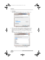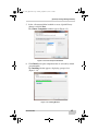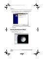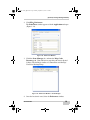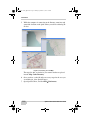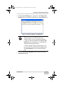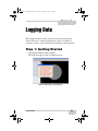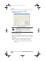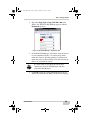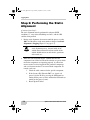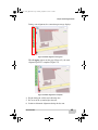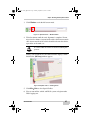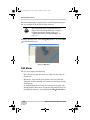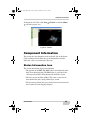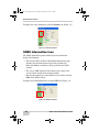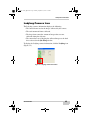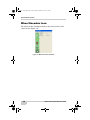
1
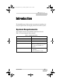
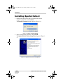
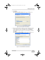
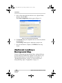
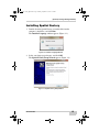
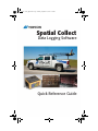
Spatial Collect_QRG.book Page 1 Monday, September 13, 2010 5:04 PM
3PATIAL#OLLECT
$ATA,OGGING3OFTWARE
1UICK2EFERENCE'UIDE
Spatial Collect_QRG.book Page 2 Monday, September 13, 2010 5:04 PM
Spatial Collect_QRG.book Page 1 Monday, September 13, 2010 5:04 PM
P O S I T I O N I N G
S Y S T E M S
Spatial Collect
Quick Reference Guide
Part Number 7010-1003
Rev A
©Copyright Topcon Positioning Systems, Inc.
September, 2010
All contents in this manual are copyrighted by Topcon. All rights reserved.
The information contained herein may not be used, accessed, copied, stored,
displayed, sold, modified, published, or distributed, or otherwise reproduced
without express written consent from Topcon.
Spatial Collect_QRG.book Page 2 Monday, September 13, 2010 5:04 PM
Terms and Conditions
Thank you for buying this Topcon product. This manual has been prepared to assist
you with the installation of the product and its use is subject to these Terms and
Conditions and those more fully set forth in the Operator’s/User’s Manual.
Usage and Safety
This product is designed for use by professionals. Always use safety precautions
when operating this or any Topcon product.
Copyrights
All information contained in this Manual is the intellectual property of, and
copyrighted material of TPS. All rights are reserved. You may not use, access, copy,
store, display, create derivative works of, sell, modify, publish, distribute, or allow
any third party access to, any graphics, content, information or data in this Manual
without TPS’ express written consent and may only use such information for the care
and operation of your Product. The information and data in this Manual are a valuable
asset of TPS and are developed by the expenditure of considerable work, time and
money, and are the result of original selection, coordination and arrangement by TPS.
Trademarks
IP-S2, Topcon, and Topcon Positioning Systems are trademarks or registered
trademarks of TPS.
Other product and company names mentioned herein may be trademarks of their
respective owners.
Disclaimer of Warranty
EXCEPT FOR SUCH WARRANTIES AND LICENSES PROVIDED WITH THE PRODUCT,
THIS MANUAL AND THE PRODUCT ARE PROVIDED “AS-IS”. TOPCON AND ITS
DISTRIBUTORS SHALL NOT BE LIABLE FOR TECHNICAL OR EDITORIAL ERRORS OR
OMISSIONS CONTAINED HEREIN; NOR FOR INCIDENTAL OR CONSEQUENTIAL
DAMAGES RESULTING FROM THE FURNISHING, PERFORMANCE OR USE OF THIS
MATERIAL OR THE PRODUCT.
Please see the Operator’s/User’s Manual for detailed information on warranties and
the license agreement which may apply to the Product.
License Agreement
Use of any computer programs or software supplied by Topcon or downloaded from
the Topcon website in connection with the Product implies acceptance of the Terms
and Conditions here and in the Operator’s/User’s Manual.
Please see the Operator’s/User’s Manual for detailed information on warranties and
the license agreement which may apply to the Product.
ECO#3954
Spatial Collect_QRG.book Page i Monday, September 13, 2010 5:04 PM
TOC
Table of Contents
Chapter 1
Introduction .......................................................... 1-1
System Requirements ......................................................
Installing Spatial Collect ..................................................
(Optional) Loading a Background Map ...........................
Installing Spatial Factory ..........................................
Caching Background Maps .......................................
1-1
1-2
1-4
1-5
1-8
Chapter 2
Logging Data ........................................................ 2-1
Step 1: Getting Started .....................................................
Step 2: Performing the Static Alignment .........................
Step 3: Kinematic Alignment ..........................................
Step 4: Shutting Down Spatial Collect ............................
2-1
2-4
2-6
2-6
Chapter 3
Spatial Collect Features ....................................... 3-1
View Icons .......................................................................
The Map View ...........................................................
3-D View ...................................................................
Component Information ...................................................
Status Information Icon .............................................
GNSS Information Icon ............................................
Ladybug Camera Icon ...............................................
Wheel Encoders Icon ................................................
P/N 7010-1003
3-1
3-1
3-2
3-3
3-3
3-4
3-5
3-6
i
Spatial Collect_QRG.book Page ii Monday, September 13, 2010 5:04 PM
Table of Contents
Notes:
ii
Spatial Collect Quick Reference Guide
Spatial Collect_QRG.book Page 1 Monday, September 13, 2010 5:04 PM
Chapter 1
Introduction
This Quick Reference Guide provides instructions for installing and
using the Spatial Collect data logging software for the IP-S2 system.
System Requirements
Your computer must meet the minimum requirements listed in
Table 1-1 to run the Spatial Collect software.
Table 1-1. System Requirements
Component
Minimum Requirements
Processor
Dual-Core 2.5 GHz or higher
RAM
4 GB
Hard Disk
75GB
Graphics
NVIDIA GeForce 9800 GT with 512
MB dedicated VRAM (ATI and graphics
cards with shared VRAM are not
supported).
Operating System
• Microsoft Windows XP Professional
64-bit SP2
• Microsoft Windows 7, 64-bit
P/N 7010-1003
1-1
Spatial Collect_QRG.book Page 2 Monday, September 13, 2010 5:04 PM
Introduction
Installing Spatial Collect
1. Double-click the Spatial Collect executable file from the
computer’s hard drive, and click Run.
The Installer Language window appears (Figure 1-1).
Figure 1-1. Installer Language Window
2. Select your language preference, and click OK.
The Spatial Factory Collect Setup Wizard appears (Figure 12).
Figure 1-2. Spatial Factory Collect Setup Wizard
1-2
Spatial Collect Quick Reference Guide
Spatial Collect_QRG.book Page 3 Monday, September 13, 2010 5:04 PM
Installing Spatial Collect
3. Click Next.
The Choose Install Location window appears (Figure 1-3).
Figure 1-3. Choose Install Location Window
4. If the destination folder in which you want to install the Spatial
Collect program is correct, click Next. If not, click Browse,
locate a different folder in which to save the program, and then
click Next.
The Choose Start Menu Folder window appears (Figure 1-4).
Figure 1-4. Choose Start Menu Folder Window
P/N 7010-1003
1-3
Spatial Collect_QRG.book Page 4 Monday, September 13, 2010 5:04 PM
Introduction
5. Select a Start menu folder in which to create a Spatial Collect
shortcut, and click Next.
The Choose Components window appears (Figure 1-5).
Figure 1-5. Choose Components Window
6. Click Install to keep the components that are selected by default
(recommended).
The Installing window appears, displaying a progress bar.
7. Once the installation is complete, click Finish on the setup
wizard.
(Optional) Loading a
Background Map
To load a background map into Spatial Collect, the Spatial Factory
program must be installed on the computer to cache the necessary
maps. If Spatial Factory is not installed on your computer, see
“Installing Spatial Factory” on page 1-5. If you do not want a
background map, skip to “Logging Data” on page 2-1.
1-4
Spatial Collect Quick Reference Guide
Spatial Collect_QRG.book Page 5 Monday, September 13, 2010 5:04 PM
(Optional) Loading a Background Map
Installing Spatial Factory
1. Double-click the Spatial Factory executable file from the
computer’s hard drive, and click Run.
The Installer Language window appears (Figure 1-1).
Figure 1-6. Installer Language Window
2. Select your language preference, and click OK.
The Spatial Factory Setup Wizard appears (Figure 1-2).
Figure 1-7. Spatial Factory Setup Wizard
P/N 7010-1003
1-5
Spatial Collect_QRG.book Page 6 Monday, September 13, 2010 5:04 PM
Introduction
3. Click Next.
The Choose Install Location window appears (Figure 1-3).
Figure 1-8. Choose Install Location Window
4. If the destination folder in which to install the Spatial Factory
program is correct, click Next. If not, click Browse, locate a
different folder in which to save the program, and then click
Next.
The Choose Start Menu Folder window appears (Figure 1-4).
Figure 1-9. Choose Start Menu Folder Window
1-6
Spatial Collect Quick Reference Guide
Spatial Collect_QRG.book Page 7 Monday, September 13, 2010 5:04 PM
(Optional) Loading a Background Map
5. Select a Start menu folder in which to create a Spatial Factory
shortcut, and click Next.
The Choose Components window appears (Figure 1-5).
Figure 1-10. Choose Components Window
6. Click Install to keep the components that are selected by default
(recommended).
The Installing window appears, displaying a progress bar
(Figure 1-11).
Figure 1-11. Installing Window
P/N 7010-1003
1-7
Spatial Collect_QRG.book Page 8 Monday, September 13, 2010 5:04 PM
Introduction
Once the installation is complete, the Completing the Spatial
Factory Setup Wizard window appears (Figure 1-12).
Figure 1-12. Completing the Spatial Factory Setup Wizard Window
7. Click Finish.
Caching Background Maps
1. Open Spatial Factory.
The main page appears (Figure 1-13).
Figure 1-13. Spatial Factory Main Page (Map View)
1-8
Spatial Collect Quick Reference Guide
Spatial Collect_QRG.book Page 9 Monday, September 13, 2010 5:04 PM
(Optional) Loading a Background Map
2. Click FilePreferences
The Preferences window appears with the Applications tab open
(Figure 1-14).
Figure 1-14. Preferences Window
3. Click the Scene Manager tab, and note the Map Cache
Directory path. (You will have to enter this path later in Spatial
Collect.) The default is similar to C:/Documents and Settings/
User/Local Settings/Temp.
Figure 1-15. Preferences Window – Scene Manager
4. Once the location is noted, close the Preferences window.
P/N 7010-1003
1-9
Spatial Collect_QRG.book Page 10 Monday, September 13, 2010 5:04 PM
Introduction
5. While the computer is connecting to the Internet, zoom into and
around the location on the globe where you will be collecting IPS2 data.
Figure 1-16. Zooming In on the Map
The map tiles that are loaded as you zoom in further are placed
into the Map Cache Directory.
6. Once you have cached all of the necessary maps for the area you
are working in, close Spatial Factory.
7. Open Spatial Collect, and click FilePreferences.
1-10
Spatial Collect Quick Reference Guide
Spatial Collect_QRG.book Page 11 Monday, September 13, 2010 5:04 PM
(Optional) Loading a Background Map
8. Click the Scene Manager tab, and type the same Map Cache
Directory that was used for Spatial Factory into the Value field.
Figure 1-17. Preferences Window – Scene Manager
NOTE
This guide assumes the Spatial Factory and Spatial
Collect programs are installed on the same
computer. If they are not, perform the following:
1. Copy the entire Temp folder in the Map Cache
Directory where the map tiles are stored onto the
computer running Spatial Collect.
2. On the computer running Spatial Collect, enter
the path of the Temp folder into the Value field on
the Scene Manager tab to load the background
map.
9. Once the Map Cache Directory has been entered, close the
Preferences window.
P/N 7010-1003
1-11
Spatial Collect_QRG.book Page 12 Monday, September 13, 2010 5:04 PM
Introduction
Notes:
1-12
Spatial Collect Quick Reference Guide
Spatial Collect_QRG.book Page 1 Monday, September 13, 2010 5:04 PM
Chapter 2
Logging Data
This chapter describes in four steps how to log data using Spatial
Collect. The user is advised to perform these steps in sequence to
ensure the accuracy of the collected data and proper system operation.
Step 1: Getting Started
1. Open Spatial Collect on the computer.
The main page appears with a warning message.
Figure 2-1. Main Page – Driver Warning
P/N 7010-1003
2-1
Spatial Collect_QRG.book Page 2 Monday, September 13, 2010 5:04 PM
Logging Data
2. Read the driver safety message, and click OK.
The Job Setup window appears.
Figure 2-2. Job Setup Window
NOTE
Do not change the host name or TCP/IP port in the
IP-S2 Settings box; otherwise, no Ethernet
connection can be made to the IP-S2 system to
begin data logging.
3. In the drive_name field, type a name for the root directory where
IP-S2 datasets will be stored.
4. Select the destination drive for each of the sensor outputs in the
IP-S2 system. You can place data from the sensors onto multiple
hard drives.
5. Confirm the IP-S2 system is powered up and all of the system
components have been successfully initialized. To do this:
1. Open a Web browser while connected to the IP-S2 via
Ethernet.
2-2
Spatial Collect Quick Reference Guide
Spatial Collect_QRG.book Page 3 Monday, September 13, 2010 5:04 PM
Step 1: Getting Started
2. Type either http://ips2 or http://192.168.2.166 in the
address bar. The IP-S2 Web Manager appears with the
Dashboard tab open.
Figure 2-3. IP-S2 Web Manager – Dashboard Tab
3. On the IP-S2 Web Manager, wait for the status circle next
to each component (Figure 2-3) to turn green, which
means the sensor is operating properly. A yellow circle
means the sensor is still activating, and a red circle means
there is an error with the sensor.
NOTE
If a status circle is red, check the sensor cable
connections, close the Web Manager, and then
reopen the Web Manager.
4. Click OK to begin the static alignment process for the
inertial measurement unit (IMU) and IP-S2 data logging.
P/N 7010-1003
2-3
Spatial Collect_QRG.book Page 4 Monday, September 13, 2010 5:04 PM
Logging Data
Step 2: Performing the Static
Alignment
(Continued from Step 1)
The static alignment must be performed in adequate GNSS
conditions, i.e. away from tall buildings and trees, with 6+ GPS
satellites being tracked.
1. During static alignment, do not move until the process reaches
100% and the notice on the main window changes from Static
Alignment to Logging (Figure 2-5 on page 2-5).
WARNING
It is critical that the vehicle is not moved during the
static alignment process. Anyone inside of the
vehicle must remain still. Anyone outside of the
vehicle should not lean on the vehicle, open doors
or the trunk, etc.
2. When the static alignment begins, confirm that all of the
component icons on the left side of the window are green, which
means the components are operating properly. A yellow icon
means a notice has been logged for that particular component,
and a red icon means there is an error with the component. To
remedy a red icon:
1. Check the cable connected to the specific component.
2. If the System, GPS, Encoder, IMU, etc. icon is red,
power-cycle the IP-S2 by pressing the OFF button (or
turning off the power system) and then the ON button (or
turning on the power system).
3. Restart Spatial Collect.
2-4
Spatial Collect Quick Reference Guide
Spatial Collect_QRG.book Page 5 Monday, September 13, 2010 5:04 PM
Step 2: Performing the Static
During static alignment, the connection percentage displays.
Figure 2-4. Static Alignment in Progress
When Logging appears on the page (Figure 2-5), the static
alignment process is complete (Figure 2-5).
Figure 2-5. Static Alignment is Complete
4. Begin driving the vehicle and collecting data.
5. Be aware of the system height clearance.
6. Perform a kinematic alignment during the data run.
P/N 7010-1003
2-5
Spatial Collect_QRG.book Page 6 Monday, September 13, 2010 5:04 PM
Logging Data
Step 3: Kinematic Alignment
(Continued from Step 2)
During data logging, it is recommended to perform a kinematic
alignment for the inertial measurement unit (IMU) to produce the best
post-processing results.
To do the kinematic alignment, perform the following during the IPS2 data run:
1. There must be at least three minutes of adequate GNSS
conditions (6+ tracked satellites) while moving at speeds in
excess of 15 mph (25 km/h).
2. During this time, the vehicle should have made at least one left
turn and one right turn.
Step 4: Shutting Down Spatial
Collect
(Continued from Step 3)
1. Park the vehicle, and click Stop at the top of the Spatial Collect
page.
Figure 2-6. Spatial Collect — Stop Button
A warning message appears, asking if you want to stop logging.
2. Click Yes.
2-6
Spatial Collect Quick Reference Guide
Spatial Collect_QRG.book Page 7 Monday, September 13, 2010 5:04 PM
Step 4: Shutting Down Spatial Collect
3. Click Window to exit the full screen mode.
Figure 2-7. Spatial Collect — Window Button
4. Wait five minutes until the static alignment is complete. Do not
move for five minutes. Anyone inside of the vehicle must remain
still. Anyone outside of the vehicle should not lean on the vehicle,
open doors or the trunk, etc.
WARNING
It is critical that the vehicle is not moved during this
process.
During static alignment, the disconnection time displays. When
finished, the Job Setup window appears.
Figure 2-8. Spatial Collect — Shutting Down
5. Click FileExit to close Spatial Collect.
6. You can turn off the vehicle and IP-S2 system or begin another
IP-S2 logging run.
P/N 7010-1003
2-7
Spatial Collect_QRG.book Page 8 Monday, September 13, 2010 5:04 PM
Logging Data
Notes:
2-8
Spatial Collect Quick Reference Guide
Spatial Collect_QRG.book Page 1 Monday, September 13, 2010 5:04 PM
Chapter 3
Spatial Collect
Features
This chapter describes how to view collected data during a data run
and how to view component information.
View Icons
In the project area of Spatial Collect there are three viewing icons:
Map View (globe icon), 3-D View (house icon), and Panoramic View
(camera icon). Two of these icons allow the user to view collected
data during a run.
This section describes the Map View and 3-D View and what type of
information each icon offers that can be accessed during a data run.
The Map View
The Map View displays the following:
• The 2-D trajectory that the vehicle has taken over the course of
the data run.
• The images, represented by blue spheres, that were collected
during the data run.
• A section of the Lidar data that was collected in real-time. (By
default, Spatial Collect shows 75m of the collected Lidar data, but
the following distance is user-defined under FilePreferences.)
P/N 7010-1003
3-1
Spatial Collect_QRG.book Page 2 Monday, September 13, 2010 5:04 PM
Spatial Collect Features
All of this information is displayed on a cached background map of
the area in which the IP-S2 data is being collected.
NOTE
The background map is an optional feature to
import. For information about how to import a
background map into Spatial Collect, see
“(Optional) Loading a Background Map” on
page 1-4.
To display the Map View, click ViewMap View or click the Globe
icon in the project area.
Figure 3-1. Map View
3-D View
The 3-D view displays the following:
• The 3-D trajectory that the vehicle has taken over the course of
the data run.
• The images, represented by blue spheres, that were collected
during the data run (although you cannot view the images during
data logging).
• A section of the data in 3-D that was collected in real-time. (By
default Spatial Collect shows 75m of the collected Lidar data, but
the following distance is user-defined under FilePreferences.)
3-2
Spatial Collect Quick Reference Guide
Spatial Collect_QRG.book Page 3 Monday, September 13, 2010 5:04 PM
Component Information
To display the 3-D View, click View3-D View or click the House
icon in the project area.
Figure 3-2. 3-D View
Component Information
This section lists the component icons on the left side of the Spatial
Collect window and describes the type of information each icon
offers that can be accessed during a data run.
Status Information Icon
The system information displays the following:
• The position of the RMS (The RMS value is also displayed on the
Map View during logging.) The RMS value is a measure of the
current precision that is being obtained by the IP-S2 system.
• The data rate for the Lidar in Mb/s. This value is a measure of
how much Lidar data is being collected per second.
• The percentage of hard drive space that has been used on any hard
drive connected to the logging computer
P/N 7010-1003
3-3
Spatial Collect_QRG.book Page 4 Monday, September 13, 2010 5:04 PM
Spatial Collect Features
To display the status information, click the System icon (Figure 3-3).
Figure 3-3. Status Information
GNSS Information Icon
The GNSS (Global Navigation Satellite Systems) information
displays the following:
• The current number of GPS + GLONASS (Global Navigation
Satellite System maintained and operated by the Russian
Federation Ministry of Defense) being tracked by the GNSS
antenna.
• The average SNR (Signal-to-Noise Ratio) value, which is the
average signal strength of the tracked satellites.
• The current solution type of the GNSS receiver and the Position
RMS of the GNSS receiver.
To display the GNSS Information, click the GPS icon (Figure 3-4).
Figure 3-4. GNSS Information
3-4
Spatial Collect Quick Reference Guide
Spatial Collect_QRG.book Page 5 Monday, September 13, 2010 5:04 PM
Component Information
Ladybug Camera Icon
The Ladybug (camera) information displays the following:
• The current frame rate for the images collected by the camera.
• The total amount of frames collected.
• The drop frame count (the amount of images that were not
collected during the data run).
• The current data rate of logging the collected images to the hard
drive selected on the Job Setup window.
To display the Ladybug camera information, click the Ladybug icon
(Figure 3-5).
Figure 3-5. Ladybug Camera Information
P/N 7010-1003
3-5
Spatial Collect_QRG.book Page 6 Monday, September 13, 2010 5:04 PM
Spatial Collect Features
Wheel Encoders Icon
The wheel encoder information displays the current velocity of the
vehicle in m/s (Figure 3-6).
Figure 3-6. Wheel Encoder Information
3-6
Spatial Collect Quick Reference Guide
Spatial Collect_QRG.book Page 1 Monday, September 13, 2010 5:04 PM
Spatial Collect_QRG.book Page 2 Monday, September 13, 2010 5:04 PM
Topcon Positioning Systems, Inc.
7400 National Drive, Livermore, CA 94550
800∙443∙4567 www.topconpositioning.com
Spatial Collect Quick Reference Guide
P/N: 7010-1003 Rev A 09/10
©2010 Topcon Corporation All rights reserved. No unauthorized duplication.