1
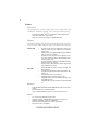
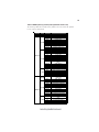
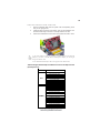
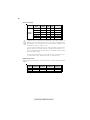
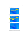
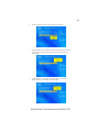
i
Preface
Copyright
This publication, including all photographs, illustrations and software, is protected
under international copyright laws, with all rights reserved. Neither this manual, nor
any of the material contained herein, may be reproduced without written consent of
the author.
Version 1.0A
Disclaimer
The information in this document is subject to change without notice. The manufacturer makes no representations or warranties with respect to the contents hereof and
specifically disclaims any implied warranties of merchantability or fitness for any
particular purpose. The manufacturer reserves the right to revise this publication and
to make changes from time to time in the content hereof without obligation of the
manufacturer to notify any person of such revision or changes.
Trademark Recognition
Microsoft, MS-DOS and Windows are registered trademarks of Microsoft Corp.
MMX, Pentium, Pentium-II, Pentium-III, Celeron are registered trademarks of Intel
Corporation.
Other product names used in this manual are the properties of their respective
owners and are acknowledged.
Federal Communications Commission (FCC)
This equipment has been tested and found to comply with the limits for a Class B
digital device, pursuant to Part 15 of the FCC Rules. These limits are designed to
provide reasonable protection against harmful interference in a residential installation. This equipment generates, uses, and can radiate radio frequency energy and, if
not installed and used in accordance with the instructions, may cause harmful interference to radio communications. However, there is no guarantee that interference
will not occur in a particular installation. If this equipment does cause harmful
interference to radio or television reception, which can be determined by turning the
equipment off and on, the user is encouraged to try to correct the interference by one
or more of the following measures:
•
•
•
•
Reorient or relocate the receiving antenna
Increase the separation between the equipment and the receiver
Connect the equipment onto an outlet on a circuit different from that to
which the receiver is connected
Consult the dealer or an experienced radio/TV technician for help
Shielded interconnect cables and a shielded AC power cable must be employed with
this equipment to ensure compliance with the pertinent RF emission limits governing this device. Changes or modifications not expressly approved by the system’s
manufacturer could void the user’s authority to operate the equipment.
Preface
ii
Declaration of Conformity
This device complies with part 15 of the FCC rules. Operation is subject to the
following conditions:
•
•
This device may not cause harmful interference, and
This device must accept any interference received, including interference that may cause undesired operation
Canadian Department of Communications
This class B digital apparatus meets all requirements of the Canadian Interferencecausing Equipment Regulations.
Cet appareil numérique de la classe B respecte toutes les exigences du Réglement sur
le matériel brouilieur du Canada.
About the Manual
The manual consists of the following:
Describes features of the
motherboard.
Chapter 1
Introducing the Motherboard
Go to
Chapter 2
H
page 1
Describes installation of
motherboard components.
Installing the Motherboard
Go to
H
page 7
Provides information on using the BIOS Setup Utility.
Chapter 3
Using BIOS
Go to
Chapter 4
Using the Motherboard Software
Chapter 5
®
Using the Intel System Recovery
Tool (Intel® SRT)
Preface
H
page 25
Describes the motherboard
software
Go to
H
page 41
Describes the motherboard
software
Go to
H
page 47
iii
TABLE OF CONTENTS
Preface
i
Chapter 1
1
Introducing the Motherboard
1
Introduction......................................................................................1
Feature...............................................................................................2
Motherboard Components.............................................................4
Chapter 2
7
Installing the Motherboard
7
Safety Precautions..........................................................................7
Choosing a Computer Case............................................................7
Installing the Motherboard in a Case............................................7
Checking Jumper Settings...............................................................8
Setting Jumpers......................................................................8
Checking Jumper Settings......................................................9
Jumper Settings......................................................................9
Installing Hardware...................................................................10
Installing the Processor........................................................10
Installing Memory Modules.................................................12
Expansion Slots....................................................................14
Connecting Optional Devices...............................................17
Installing a Hard Disk Drive/CD-ROM/SATA Hard Drive..19
Installing a Floppy Diskette Drive.......................................20
Connecting I/O Devices................................................................21
Connecting Case Components.....................................................22
Front Panel Header..............................................................24
Chapter 3
25
Using BIOS
25
About the Setup Utility.................................................................25
The Standard Configuration................................................25
Entering the Setup Utility......................................................25
Using BIOS.....................................................................................26
Main Features.....................................................................27
Advanced Features..............................................................28
iv
PCI Configuration..............................................................28
Boot Configuration.............................................................29
Peripheral Configuration....................................................29
IDE Configuration..............................................................30
Video Configuration............................................................31
USB Configuration..............................................................31
Chipset Configuration............................................................32
Performance Support.......................................................... 33
System Health.....................................................................34
Security Features.................................................................35
Power Features..................................................................36
Boot....................................................................................38
Exit.....................................................................................38
Updating the BIOS.............................................................40
41
Chapter 4
Using the Motherboard Software
41
About the Software CD-ROM.......................................................41
Auto-installing under Windows 2000/XP/Vista.........................41
Running Setup....................................................................42
Manual Installation.........................................................................46
Utility Software Reference.............................................................46
47
Chapter 5
®
®
Using the Intel System Recovery Tool (Intel SRT)
47
About the Intel® System Recovery Tool.....................................47
Features............................................................................................47
Installation Step..............................................................................48
Feature Notes..................................................................................53
1
Chapter 1
Introducing the Motherboard
Introduction
Thank you for choosing the ISRT 945GCT-M motherboard. This motherboard is a
high performance, enhanced function motherboard designed to support the LGA775
socket Intel® CoreTM 2 Duo/Pentium® Dual Core/Pentium® D/Pentium® 4/Celeron® D
processors for high-end business or personal desktop markets.
The motherboard incorporates the 945GC Northbridge (NB) and ICH7 Southbridge
(SB) chipsets. The Northbridge supports a Front Side Bus (FSB) frequency of 1066/
800/533 MHz using a scalable FSB Vcc_CPU. The memory controller supports
DDR2 memory DIMM frequencies of 667/533/400. It supports two DDR2 sockets
with up to maximum memory of 2 GB. DDR2 Maximum memory bandwidth of 10.7
Gb/s in dual-channel interleaved mode using DDR2 667 MHz. High resolution graphics via two PCI Express slots, intended for Graphics Interface, are fully compliant to
the PCI Express Base Specification revision 1.0a.
The ICH7 Southbridge supports two PCI slots which are PCI 2.3 compliant. It
implements an EHCI compliant interface that provides 480 Mb/s bandwidth for
eight USB 2.0 ports. One onboard IDE connector supports 2 IDE devices in Ultra
ATA 100/66/33 mode. The Southbridge integrates a Serial ATA host controller that
is SATA 1.0a compliant, supporting four SATA ports with maximum transfer rate up
to 3.0 Gb/s each.
The motherboard is equipped with advanced full set of I/O ports in the rear panel,
including PS/2 mouse and keyboard connectors, COM1, one VGA port, four USB
ports, one LAN port and audio jacks for microphone, line-in and line-out.
Introducing the Motherboard
2
Feature
Processor
The motherboard uses an LGA775 type of Intel® CoreTM 2 Duo/Pentium® Dual
Core/Pentium® D/Pentium® 4/Celeron® D that carries the following features:
•
•
Accommodates Intel® CoreTM 2 Duo/Pentium® Dual Core/Pentium®
D/Pentium® 4/Celeron® D processors
Supports a system bus (FSB) of 1066/800/533 MHz
Chipset
The 945GC Northbridge (NB) and ICH7 Southbridge (SB) chipsets are based on
an innovative and scalable architecture with proven reliability and performance.
945GC (NB)
•
•
•
•
•
ICH7 (SB)
•
•
•
•
•
•
Memory
•
•
•
Supports 32-bit host bus addressing, allowing the
CPU to access the entire 2 GB of the memory address space
2 GB/s point-to-point Direct Media Interface (DMI) to
ICH7 (1 Gb/s) each direction
Supports one PCI Express x16 for Graphics Interface, fully compliant to the PCI Express Base Specification revision 1.0a.
Supports 256-Mb, 512-Mb and 1-Gb DDR2 technologies for x8 and x16 devices
Supports high quality 3D setup, Render Engine and
high-quality texture engine
Enhanced DMA Controller, interrupt controller, and
timer functions
Compliant with PCI Express Base Specification, Revision 1.0a
Compliant with PCI 2.3 specification
Integrated SATA 3.0 Gb/s Host Controller
Integrated USB 2.0 Host Controller supporting up to
eight USB 2.0 ports
Integrated IDE controller supports Ultra ATA 100/66/
33
Supports DDR2 667/533/400 DDR SDRAM with Dual-channel architecture
Accommodates two unbuffered DIMMs
Up to 1 GB per DIMM with maximum memory size up to 2 GB
Audio
•
•
•
•
•
5.1 channel High Definition Audio Codec
All DACs Support 192K/96K/48K/44.1KHz DAC sample rate
Software selectable 2.5V/3.75V VREFOUT
Meets Microsoft WHQL/WLP 2.x audio requirements
Direct Sound 3DTM compatible
Introducing the Motherboard
3
Onboard LAN (Optional)
The onboard LAN controller provides the following features:
•
•
•
•
•
•
Integrated 10/100/1000 transceiver
Supports PCI v2.3, 32-bit, 33/66 MHz
Supports Wake-On-LAN (WOL) function and remote wake-up
Supports 10/100 Mb/s N-Way Auto negotiation operation
Half/Full duplex capacity
Supports Wake-On-LAN (WOL) function and remote wake-up
Expansion Options
The motherboard comes with the following expansion options:
•
Two PCI Express slots for Graphics Interface
•
Two 32-bit PCI v2.3 compliant slots
•
One IDE connector that supports two IDE devices
•
One floppy disk drive interface
•
Four 7-pin SATA connectors
The motherboard supports UDMA bus mastering with transfer rates of 100/66/33
Mb/s.
Integrated I/O
The motherboard has a full set of I/O ports and connectors:
•
•
•
•
•
•
Two PS/2 ports for mouse and keyboard
One serial port
One VGA port
Four USB ports
One LAN port
Audio jacks for microphone, line-in and line-out
BIOS Firmware
This motherboard uses Insyde BIOS that enables users to configure many system
features including the following:
•
Power management
•
Wake-up alarms
•
CPU parameters
•
CPU and memory timing
The firmware can also be used to set parameters for different processor clock
speeds.
1. Some hardware specifications and software items are subject to change
without prior notice.
2. Due to chipset limitation, we recommend that motherboard be operated
in the ambiance between 0 and 50 ° C.
Introducing the Motherboard
4
Motherboard Components
Introducing the Motherboard
5
Table of Motherboard Components
LABEL
1. CPU Socket
2. CPU_FAN
3. DIMM1/3
4. FDD
5. ATX1
6. IDE1
7. SATA1~4
8. F_PANEL
9. CLR_CMOS1
10. F_USB1~2
11. PWR_FAN*
12. SPDIFO
13. F_AUDIO
14. CD_IN
15. PCI1~2
16. PCIEX4
17. PCIEX16
18. SYS_FAN
19. ATX12V
COMPONENTS
®
®
LGA775 socket for Intel CoreTM 2 Duo/Pentium
®
®
®
Dual Core/Pentium D/Pentium 4/Celeron D CPUs
CPU cooling fan connector
240-pin DDR2 SDRAM slots
Floppy disk drive connector
Standard 24-pin ATX power connector
Primary IDE connector
Serial ATA connectors
Front panel switch/LED header
Clear CMOS jumper
Front Panel USB headers
Power cooling fan connector
SPDIF out header
Front panel audio header
Analog audio input connector
32-bit add-on card slots
PCI Express Lite for graphics interface
PCI Express slot for graphics interface
System cooling fan connector
Auxiliary 4-pin power connector
“*” stands for optional components.
This concludes Chapter 1. The next chapter explains how to install the motherboard.
Introducing the Motherboard
6
Memo
Introducing the Motherboard
7
Chapter 2
Installing the Motherboard
Safety Precautions
•
•
•
•
•
Follow these safety precautions when installing the motherboard
Wear a grounding strap attached to a grounded device to avoid damage from static electricity
Discharge static electricity by touching the metal case of a safely
grounded object before working on the motherboard
Leave components in the static-proof bags they came in
Hold all circuit boards by the edges. Do not bend circuit boards
Choosing a Computer Case
There are many types of computer cases on the market. The motherboard complies
with the specifications for the Micro ATX system case. First, some features on the
motherboard are implemented by cabling connectors on the motherboard to indicators and switches on the system case. Make sure that your case supports all the
features required. Secondly, this motherboard supports one floppy diskette drive and
two enhanced IDE drives. Make sure that your case has sufficient power and space for
all drives that you intend to install.
Most cases have a choice of I/O templates in the rear panel. Make sure that the I/O
template in the case matches the I/O ports installed on the rear edge of the
motherboard.
This motherboard carries a Micro ATX form factor of 244 x 220 mm. Choose a case
that accommodates this form factor.
Installing the Motherboard in a Case
Refer to the following illustration and instructions for installing the motherboard in
a case.
Most system cases have mounting brackets installed in the case, which correspond
the holes in the motherboard. Place the motherboard over the mounting brackets
and secure the motherboard onto the mounting brackets with screws.
Ensure that your case has an I/O template that supports the I/O ports and expansion
slots on your motherboard.
Installing the Motherboard
8
Do not over-tighten the screws as this can stress the motherboard.
Checking Jumper Settings
This section explains how to set jumpers for correct configuration of the motherboard.
Setting Jumpers
Use the motherboard jumpers to set system configuration options. Jumpers with
more than one pin are numbered. When setting the jumpers, ensure that the jumper
caps are placed on the correct pins.
The illustrations show a 2-pin jumper. When
the jumper cap is placed on both pins, the
jumper is SHORT. If you remove the jumper
cap, or place the jumper cap on just one pin,
the jumper is OPEN.
SHORT
This illustration shows a 3-pin jumper. Pins
1 and 2 are SHORT.
Installing the Motherboard
OPEN
9
Checking Jumper Settings
The following illustration shows the location of the motherboard jumpers. Pin 1 is
labeled.
Jumper Settings
Jumper
Type
Description
Setting (default)
1-2: Clear CMOS
CLR_CMOS1 3-pin
2-3: Normal
Clear CMOS
Before clearing the
CMOS, make sure to
turn off the system.
1
CLR_CMOS1
To avoid the system instability after clearing CMOS, we recommend
users to enter the main BIOS setting page to “Load Optimal Defaults”
and then “Save Changes and Exit”.
Installing the Motherboard
10
Installing Hardware
Installing the Processor
Caution: When installing a CPU heatsink and cooling fan make sure
that you DO NOT scratch the motherboard or any of the surfacemount resistors with the clip of the cooling fan. If the clip of the
cooling fan scrapes across the motherboard, you may cause serious
damage to the motherboard or its components.
On most motherboards, there are small surface-mount resistors near
the processor socket, which may be damaged if the cooling fan is
carelessly installed.
Avoid using cooling fans with sharp edges on the fan casing and the
clips. Also, install the cooling fan in a well-lit work area so that you
can clearly see the motherboard and processor socket.
Before installing the Processor
This motherboard has a LGA775 socket. When choosing a processor, consider the
performance requirements of the system. Performance is based on the processor
design, the clock speed and system bus frequency of the processor, and the quantity
of internal cache memory and external cache memory.
This motherboard automatically determines the CPU clock frequency and system
bus frequency for the processor. You may be able to change the settings in the system
Setup Utility. We strongly recommend that you do not over-clock processors or
other components to run faster than their rated speed.
Warning:
1. Over-clocking components can adversely affect the reliability of
the system and introduce errors into your system. Over-clocking can
permanently damage the motherboard by generating excess heat in
components that are run beyond the rated limits.
2. Always remove the AC power by unplugging the power cord from
the power outlet before installing or removing the motherboard or
other hardware components.
Fail-Safe Procedures for Over-clocking
When end-users encounter failure after attempting over-clocking, please take the
following steps to recover from it.
1. Shut down the computer.
2. Press and hold the “Page Up Key (PgUp)” of the keyboard, and then boot the
PC up.
3. Two seconds after the PC boots up, release the “Page Up Key (PgUp)”.
4. The BIOS returns to the default setting by itself.
Installing the Motherboard
11
CPU Installation Procedure
The following illustration shows CPU installation components.
A. Read and follow the instructions shown on the
sticker on the CPU cap.
B. Unload the cap
· Use thumb & forefinger to hold the
lifting tab of the cap.
· Lift the cap up and remove the cap
completely from the socket.
C. Open the load plate
· Use thumb & forefinger to hold the
hook of the lever, pushing down and pulling
aside unlock it.
· Lift up the lever.
· Use thumb to open the load plate. Be
careful not to touch the contacts.
D. Install the CPU on the socket
· Orientate CPU package to the socket.
Make sure you match triangle marker
to pin 1 location.
E. Close the load plate
· Slightly push down the load plate onto the
tongue side, and hook the lever.
· CPU is locked completely.
F. Apply thermal grease on top of the CPU.
G. Fasten the cooling fan supporting base onto
the CPU socket on the motherboard.
H. Make sure the CPU fan is plugged to the
CPU fan connector. Please refer to the CPU
cooling fan user’s manual for more detail
installation procedure.
1. To achieve better airflow rates and heat dissipation, we suggest that you
use a high quality fan with 3800 rpm at least. CPU fan and heatsink
installation procedures may vary with the type of CPU fan/heatsink sup
plied. The form and size of fan/heatsink may also vary.
2. DO NOT remove the CPU cap from the socket before installing a CPU.
3. Return Material Authorization (RMA) requests will be accepted only if the
motherboard comes with the cap on the LGA775 socket.
Installing the Motherboard
12
Installing Memory Modules
This motherboard accommodates two memory modules. It can support two 240-pin
DDR2 667/533/400. The total memory capacity is 2 GB.
DDR2 SDRAM memory module table
Memory module
Memory Bus
DDR2 400
DDR2 533
200 MHz
266 MHz
DDR2 667
333 MHz
You must install at least one module in any of the two slots. Each module can be
installed with 256 MB to 1 GB of memory; total memory capacity is 2 GB.
Do not remove any memory module from its antistatic packaging
until you are ready to install it on the motherboard. Handle the
modules only by their edges. Do not touch the components or metal
parts. Always wear a grounding strap when you handle the modules.
Installation Procedure
Refer to the following to install the memory modules.
1
2
3
4
5
6
This motherboard supports unbuffered DDR2 SDRAM .
Push the latches on each side of the DIMM slot down.
Align the memory module with the slot. The DIMM slots are keyed with
notches and the DIMMs are keyed with cutouts so that they can only be
installed correctly.
Check that the cutouts on the DIMM module edge connector match the
notches in the DIMM slot.
Install the DIMM module into the slot and press it firmly down until it
seats correctly. The slot latches are levered upwards and latch on to
the edges of the DIMM.
Install any remaining DIMM modules.
Installing the Motherboard
13
Table A: DDR2 (memory module) QVL (Qualified Vendor List)
The following DDR2 667/533/400 memory modules have been tested and qualified
for use with this motherboard.
Type
Size
DDR2 400 512 MB
256 MB
DDR2 533
512 MB
1 GB
256 MB
512 MB
DDR2 667
1 GB
Vendor
Module Name
TwinMos
msung K4T51083QB-GCCC
Corsair
Corsair
Eipida
Hynix
Kingston
Kingmax
Kingston
Nanya
Ramaxel
Ramaxel
Aeneon
Aeneon
Corsair
Eipida
Hynix
Infineon
Kingston
Kingston
PQI
Aeneon AET94F-370
VC256MB533D2 4PB11D9CHM
E2508AA-DF-E
HY5PS121621
Elpida E5116F-5C-E
Hynix HY5PS121621
Infineon HYB18T512260AF-3.7
NT5TU32M16AG-37B
Elpida E5116AF-5C-E
5PB42 D9DCD
AET93F370
AET94F370
Samsung K4T51083QB-ZCD5
04180WB01
HY5PS12821
HY818T512800AF37 33346778
Hynix HYB18T512800AF37
Hynix HY5PS12821
PQI PQB2648D38R0701
PC2-4200U-444 LF 6AD11
Ramaxel
D9GCT
Ramaxel
5PB32 D9DCN
Samsung
K4T51083QC
Samsung
K4T51083QF-ZCD5
Twinmos
Elpida E5108AB-5C-E
Apacer
Elpida E5108AB-5C-E
Geil
A016E2864T2AG8AKT5H120001
Infineon
HY818T512800AF37 33344539
Kingmax
KKEA88E4AAKG-37
PQI
PQI PQB2648D38R0651
UMAX
U2S12D30TP-5C
Infineon
HYS64T325001HU-3-A
HYB18T256
Ramxel
5NB31 D9DCG
A-DATA
AD29608A88-3EG
Corsair
Corsair K4T5108QC
Corsair
VALUESELECT 32M8CEC
GEIL
GEIL GL2L64M088BA30AW
GEIL
GL2L64M088BA18W
Ramxel
5LB31 D9DCL
Samsung
K4T51083QC
Sync
Max 04400WB01 R050008A
Transcend
JetRam J12Q3AB-6
Transcend
SEL520ZCE6 K4T51083QC
Twinmos
TMM6208G8M30B
Apacer
Elpida AM4B5708GEWS7E0637F
Infineon
HYB18T51512800BF3S
PQI
PQI PQB2648D38R0648
Samsung
K4T51083QC
UMAX
U2S12030TP-6E TBF614-L93G
Installing the Motherboard
14
Expansion Slots
Installing Add-on Cards
The slots on this motherboard are designed to hold expansion cards and connect
them to the system bus. Expansion slots are a means of adding or enhancing the
motherboard’s features and capabilities. With these efficient facilities, you can increase the motherboard’s capabilities by adding hardware that performs tasks that are
not part of the basic system.
PCIEX16
Slot
The PCI Express slot is used to install an external PCI Express graphics card that is fully compliant to the PCI Express Base Specification
revision 1.0a.
PCIEX4
The PCI Express Lite is used to install an external PCI Express graphics card that is fully compliant to the PCI Express Base Specification
revision 1.0a.
Lite
PCI 1~2
Slots
This motherboard is equipped with two standard PCI slots. PCI stands
for Peripheral Component Interconnect and is a bus standard for
expansion cards, which for the most part, is a supplement of the older
ISA bus standard. The PCI slots on this board are PCI v2.3 compliant.
Before installing an add-on card, check the documentation for the
card carefully. If the card is not Plug and Play, you may have to
manually configure the card before installation.
Installing the Motherboard
15
Follow these instructions to install an add-on card:
1
2
3
Remove a blanking plate from the system case corresponding to the
slot you are going to use.
Install the edge connector of the add-on card into the expansion slot.
Ensure that the edge connector is correctly seated in the slot.
Secure the metal bracket of the card to the system case with a screw.
1. For some add-on cards, for example graphics adapters and network
adapters, you have to install drivers and software before you can begin
using the add-on card.
2. The onboard PCI interface does not support 64-bit SCSI cards.
Table B: Supported PCI Express VGA Card List for PCI Express Slot
(PCI Express x4)
VGA Chip
Model Name
ASUS EAX1900XT 512MB
ASUS EAX1950XTX 512MB
ASUS X800XT 256MB
ASUS X850XT PE 246MB
ATI
ATI X1600XT 256M
Colorful X300SE 128MB
GIGABYTE X700PRO128MB
MSI RX550 256MB
MSI X1300 256MB
Albatron 256MB7600GT 256M
ASUS EN7600GS 512MB
BITC 6200TC 16MB
ELSA 6600GT 128MB
GEFORCE 7300GS128MB
GEFORCE 6600LE 256MB
GIGABYTE GV-NX73TC512DL-RH
GF7300GS 512MB
NVIDIA
GIGABYTE 6200 128MB
Leadtek 6800 Ultra 256MB
NVIDIA PVX5300 128MB
NVIDIA PCX5750 128MB
PIxelView PV-N70GXE 256MB
WinfastPX6500 128MB
Winfast PX6600GT128MB
Winfast 6800GS 256MB
Winfast PX7900GT 256MB
Installing the Motherboard
16
Surround Display
Function
Init Display Onboard PCI-E PCI-E
Test Result
First
VGA
x16
x4
PCI-E Card
Install
WinXP
o
x
x
pass
PCI-E Card
x
o
x
pass
PCI-E Card
x
x
o
pass
o
pass
PCI-E Card
o
x
Onboard VGA
o
x
o
Not support
PCI-E Card
x
o
o
Not support
1. When the driver of onboard VGA is installed first, the primary Graphics in
Windows will be onboard VGA. However, if the driver of add-on PCI Express Graphics card is installed first, the primary Graphics in Windows will
be add-on PCI Express Graphics card.
2. If you install the add-on PCI Express VGA card, BIOS setup will automatically disable the onboard VGA after loading optimal defaults. To enable the Surround Display function, make sure to manually enable onboard
VGA in the BIOS setting.
3. When using surround display, please make sure that “Init Display First”
in “CMOS Setup Utility” should be selected to “Onboard VGA”.
ADD2 Card Function
When you want to perform dual view (clone) function, only the following assemble
supports.
Function PCI-E x16 PCI-E x4
Dual View
(Clone)
o
x
Test Result
pass
Installing the Motherboard
Remark
17
Connecting Optional Devices
Refer to the following for information on connecting the motherboard’s optional
devices:
F_AUDIO: Front Panel Audio header
This header allows the user to install auxiliary front-oriented microphone and lineout ports for easier access.
Pin
1
2
3
4
5
6
7
AUD_MIC
Signal Name
Function
Pin
Front Panel Microphone input signal
AUD_GND
Ground used by Analog Audio Circuits
MIC_BIAS
Microphone Power
8
9
10
Key
No Pin
AUD_F_L
Left Channel Audio signal to Front Panel
AUD_RET_L
Left Channel Audio signal to Return from Front Panel
AUD_VCC
Filtered +5V used by Analog Audio Circuits
AUD_F_R
Right Channel audio signal to Front Panel
AUD_RET_R
RightChannelAudiosignaltoReturnfromFrontPanel
REVD
Reserved
CD_IN: Analog Audio Input connector
Pin
1
2
3
4
Signal Name
Signal Name
Function
CD_L
CD In right channel
GND
Ground
GND
CD_R
Ground
CD In left channel
Installing the Motherboard
18
SATA1~4: Serial ATA connectors
These connectors are used to support the new Serial ATA devices for the highest data
transfer rates (3.0 Gb/s), simpler disk drive cabling and easier PC assembly. It eliminates limitations of the current Parallel ATA interface. But maintains register compatibility and software compatibility with Parallel ATA.
Pin
Signal Name
1
3
Ground
5
7
Pin
Signal Name
TX+
TX-
2
4
RXGround
6
-
RX+
-
Ground
F_USB1~2: Front Panel USB headers
The motherboard has four USB ports installed on the rear edge I/O port array.
Additionally, some computer cases have USB ports at the front of the case. If you
have this kind of case, use auxiliary USB connector to connect the front-mounted
ports to the motherboard.
Pin
Signal Name
Function
1
USBPWR
2
3
4
5
6
7
8
9
10
USBPWR
Front Panel USB Power
USB_FP_P0-
USB Port 0 Negative Signal
USB_FP_P1-
USB Port 1 Negative Signal
Front Panel USB Power
USB_FP_P0+
USB Port 0 Positive Signal
USB_FP_P1+
USB Port 1 Positive Signal
GND
GND
Ground
Ground
Key
No pin
USB_FP_OC0
Overcurrent signal
Please make sure that the USB cable has the same pin assignment as
indicated above. A different pin assignment may cause damage or system
hang-up.
SPDIFO: SPDIF out header
This is an optional header that provides an SPDIFO (Sony/Philips Digital Interface)
output to digital multimedia device through optical fiber or coaxial connector.
Pin
Signal Name
1
2
3
4
SPDIFOUT
+5V
Key
GND
Installing the Motherboard
19
Installing a Hard Disk Drive/CD-ROM/SATA Hard Drive
This section describes how to install IDE devices such as a hard disk drive and a CDROM drive.
About IDE Devices
Your motherboard has one IDE channel interface. An IDE ribbon cable supporting
two IDE devices is bundled with the motherboard.
You must orient the cable connector so that the pin1 (color) edge of
the cable corresponds to the pin 1 of the I/O port connector.
IDE1: IDE Connector
This motherboard supports four high data transfer SATA ports with each runs up to
3.0 Gb/s. To get better system performance, we recommend users connect the CDROM to the IDE channel, and set up the hard dives on the SATA ports.
IDE devices enclose jumpers or switches used to set the IDE device as MASTER or
SLAVE. Refer to the IDE device user’s manual. Installing two IDE devices on one
cable, ensure that one device is set to MASTER and the other device is set to SLAVE.
The documentation of your IDE device explains how to do this.
About SATA Connectors
Your motherboard features four SATA connectors supporting a total of four drives.
SATA refers to Serial ATA (Advanced Technology Attachment) is the standard interface for the IDE hard drives which are currently used in most PCs. These connectors
are well designed and will only fit in one orientation. Locate the SATA connectors on
the motherboard and follow the illustration below to install the SATA hard drives.
Installing Serial ATA Hard Drives
To install the Serial ATA (SATA) hard drives, use the SATA cable that supports the
Serial ATA protocol. This SATA cable comes with an SATA power cable. You can
connect either end of the SATA cable to the SATA hard drive or the connector on the
motherboard.
SATA cable
(optional)
SATA power cable
Installing the Motherboard
(optional)
20
Refer to the illustration below for proper installation:
1
2
3
Attach either cable end to the connector on the motherboard.
Attach the other cable end to the SATA hard drive.
Attach the SATA power cable to the SATA hard drive and connect the
other end to the power supply.
This motherboard does not support the “Hot-Plug” function.
Installing a Floppy Diskette Drive
FDD: Floppy Disk Connector
Connect the single end of the of the floppy connector to the onboard floppy
connector firstly, and then connect the remaining plugs on the other end to the
floppy drives correspondingly.
You must orient the cable connector so that the pin 1 (color) edge of
the cable corresponds to the pin 1 of the I/O port connector.
Installing the Motherboard
21
Connecting I/O Devices
The backplane of the motherboard has the following I/O ports:
PS2 Mouse
Use the upper PS/2 port to connect a PS/2 pointing device.
PS2 Keyboard
Use the lower PS/2 port to connect a PS/2 keyboard.
Serial Port
(COM1)
Use the COM port to connect serial devices such as mice or
fax/modems.
VGA Port
Connect your monitor to the VGA port.
LAN Port
Connect an RJ-45 jack to the LAN port to connect your
computer to the Network.
USB Ports
Use the USB ports to connect USB devices.
Audio Ports
Use the three audio jacks to connect audio devices. The first
jack is for stereo line-in signal. The second jack is for stero
line-out signal. The third jack is for microphone.
Installing the Motherboard
22
Connecting Case Components
After you have installed the motherboard into a case, you can begin connecting the
motherboard components. Refer to the following:
1
Connect the CPU cooling fan cable to CPU_FAN.
2
Connect the system cooling fan connector to SYS_FAN.
3
Connect the case switches and indicator LEDs to the F_PANEL.
4
Connect the standard power supply connector to ATX1.
5
Connect the auxiliary case power supply connector to ATX12V.
6
Connect the power fan connector to PWR_FAN (optional).
Connecting 24-pin power cable
The ATX 24-pin connector allows you to connect to ATX v2.x power
supply.
With ATX v2.x power supply, users please
note that when installing 24-pin power
cable, the latches of power cable and the
ATX1 match perfectly.
24-pin power cable
Connecting 4-pin power cable
The ATX12V power connector is used to provide power to the CPU.
When installing 4-pin power cable, the
latches of power cable and the ATX12V
match perfectly.
4-pin power cable
Installing the Motherboard
23
CPU_FAN: FAN Power Connector
Pin
1
2
3
4
Signal Name
GND
+12V
Sense
Control
Function
System Ground
Power +12V
Sensor
CPU FAN control
Users please note that the fan connector supports the CPU cooling fan of
1.1A ~ 2.2A (26.4W max) at +12V.
SYS_FAN: System Cooling FAN Power Connector
Pin
1
2
3
Signal Name
Function
System Ground
Power +12V
Sensor
GND
+12V
Sense
ATX1: ATX 24-pin Power Connector
Pin
Signal Name
1
2
3
4
5
6
7
8
9
+3.3V
10
11
12
+12V
Pin
13
14
15
16
17
18
19
20
21
+3.3V
Ground
+5V
Ground
+5V
Ground
PWRGD
+5VSB
22
23
24
+12V
+3.3V
Signal Name
+3.3V
-12V
Ground
PS_ON
Ground
Ground
Ground
-5V
+5V
+5V
+5V
Ground
ATX12V: ATX 12V Power Connector
Pin
1
2
3
4
Signal Name
Ground
Ground
+12V
+12V
PWR_FAN: FAN Power Connector (optional)
Pin
1
2
3
Signal Name
GND
+12V
NC
Function
System Ground
Power +12V
Not connect
Installing the Motherboard
24
Front Panel Header
The front panel header (F_PANEL) provides a standard set of switch and LED
headers commonly found on ATX or Micro ATX cases. Refer to the table below for
information:
Pin
Signal
Function
Pin
Signal
Function
1
HD_LED_P Hard disk LED(+)
2
FP PWR/SLP *MSG LED(+)
3
HD_LED_N Hard disk LED(- )
4
FP PWR/SLP *MSG LED(-)
5
RST_SW_N Reset Switch(-)
6
PWR_SW_P Power Switch(+)
7
RST_SW_P
Reset Switch(+)
8
PWR_SW_N Power Switch(-)
9
RSVD
Reserved
10 Key
No pin
* MSG LED (dual color or single color)
Hard Drive Activity LED
Connecting pins 1 and 3 to a front panel mounted LED provides visual indication
that data is being read from or written to the hard drive. For the LED to function
properly, an IDE drive should be connected to the onboard IDE interface. The LED
will also show activity for devices connected to the SCSI (hard drive activity LED)
connector.
Power/Sleep/Message waiting LED
Connecting pins 2 and 4 to a single or dual-color, front panel mounted LED provides
power on/off, sleep, and message waiting indication.
Reset Switch
Supporting the reset function requires connecting pins 5 and 7 to a momentarycontact switch that is normally open. When the switch is closed, the board resets and
runs POST.
Power Switch
Supporting the power on/off function requires connecting pins 6 and 8 to a momentary-contact switch that is normally open. The switch should maintain contact for at
least 50 ms to signal the power supply to switch on or off. The time requirement is
due to internal de-bounce circuitry. After receiving a power on/off signal, at least two
seconds elapses before the power supply recognizes another on/off signal.
This concludes Chapter 2. The next chapter covers the BIOS.
Installing the Motherboard
25
Chapter 3
Using BIOS
About the Setup Utility
The computer uses the latest Insyde BIOS with support for Windows Plug and Play.
The CMOS chip on the motherboard contains the ROM setup instructions for configuring the motherboard BIOS.
The BIOS (Basic Input and Output System) Setup Utility displays the system’s
configuration status and provides you with options to set system parameters. The
parameters are stored in battery-backed-up CMOS RAM that saves this information
when the power is turned off. When the system is turned back on, the system is
configured with the values you stored in CMOS.
The BIOS Setup Utility enables you to configure:
•
•
•
•
Hard drives, diskette drives and peripherals
Video display type and display options
Password protection from unauthorized use
Power Management features
The settings made in the Setup Utility affect how the computer performs. Before
using the Setup Utility, ensure that you understand the Setup Utility options.
This chapter provides explanations for Setup Utility options.
The Standard Configuration
A standard configuration has already been set in the Setup Utility. However, we
recommend that you read this chapter in case you need to make any changes in the
future.
This Setup Utility should be used:
•
•
•
•
•
when changing the system configuration
when a configuration error is detected and you are prompted to make
changes to the Setup Utility
when trying to resolve IRQ conflicts
when making changes to the Power Management configuration
when changing the password or making other changes to the Security
Setup
Entering the Setup Utility
When you power on the system, BIOS enters the Power-On Self Test (POST)
routines. POST is a series of built-in diagnostics performed by the BIOS. After the
POST routines are completed, the following message appears:
Using BIOS
26
Using BIOS
When you start the Setup Utility, the main menu appears. The main menu of the
Setup Utility displays a list of the options that are available. A highlight indicates
which option is currently selected. Use the cursor arrow keys to move the highlight
to other options. When an option is highlighted, execute the option by pressing
<Enter>.
Some options lead to pop-up dialog boxes that prompt you to verify that you wish to
execute that option. Other options lead to dialog boxes that prompt you for information.
Some options (marked with a triangle f) lead to submenus that enable you to change
the values for the option. Use the cursor arrow keys to scroll through the items in the
submenu.
In this manual, default values are enclosed in parenthesis. Submenu items are denoted
by a triangle f .
The default BIOS setting for this motherboard applies for most conditions with
optimum performance. It is not suggested to change the default values in the
BIOS setup and the manufacture takes no responsibility to any damage caused
by changing the BIOS settings.
BIOS Navigation Keys
The BIOS navigation keys are listed below:
KEY
FUNCTION
<>
Select Screen
qr
Select Item
+-
Change Field
Tab
Select Field
F1
General Help
F9
Setup Defaults
F10
Save and Exit
ESC
Exit
For the purpose of better product maintenance, the manufacture reserves the
right to change the BIOS items presented in this manual. The BIOS setup
screens shown in this chapter are for reference only and may differ from the
actual BIOS. Please visit the manufacture’s website for updated manual.
Using BIOS
27
Main Features
This option displays basic information about your system.
Main
Advanced
InsydeH2O Setup Utility
Security
Power
Insyde H2O version
945GCT-M Ver 1.4
07/10/2007
Processor Type
System Bus Speed
System Memory Speed
Cache RAM
Genuine Intel (R)CPU
@ 2.40GHz
200 MHz
[Not Detected]
512 KB
Total Memory
Channel Status
DIMM 0
DIMM 1
[Not Detected]
Single Channel
[Not Installed]
[Not Installed]
ISRT Language
<English>
System Time
System Date
[05:38:45]
[01/01/2004]
Boot
Exit
Select the current
default language used
by the InsydeH2O.
+-
Select Boot Device
Selecct Screen
Select Item
Enter Select fSubMenu
F9 = Setup Defaults
F10 = Save and Exit
Esc = Exit
<>
mn
Insyde H2O version (945GCT-M Ver 1.4)
This item shows Insyde H2O version.
Processor Type
The item is automatically detected by the system at start up time. The Processor
item shows the processor type and speed installed in your computer. This is displayonly field.You cannot make changes to this field.
System Bus/Memory Speed
This item shows the speed of Bus and Memory.
Cache RAM (512 KB)
This item shows cache size of RAM.
Total Memory (Not Detected)
The item is automatically detected by the system at start up time. This is displayonly field. You cannot make changes to this field.
Channel Status (Single Channel)
About the channel status, it will show “Single Channel” if memory slot plugs one
memory DIMM. Otherwise, it will show “Dual Channel” if memory slot plugs two
memory DIMMs.
DIMM 0/1 (Not Installed)
This item shows the memory capacity of DIMM.
ISRT Language (English)
This item determines the Language version of the BIOS.
System Time and Date
The System Time and Date items show the current date and time on the computer.
If you are running a Windows OS, these items are automatically updated whenever
you make changes to the Windows Date and Time Properties utility.
Using BIOS
28
fAdvanced Features
This option defines advanced information about your system.
Main
f
f
f
f
f
f
f
f
f
Advanced
InsydeH2O Setup Utility
Power
Security
Boot
Exit
PCI Configuration
PCI Configuration
Boot Configuration
Peripheral Configuration
IDE Configuration
Video Configuration
USB Configuration
Chipset Configration
Performance Support
System Health
+-
Select Boot Device
Selecct Screen
Select Item
Enter Select fSubMenu
F9 = Setup Defaults
F10 = Save and Exit
Esc = Exit
<>
mn
fPCI Configuration (Press Enter)
Scroll to this item and press <Enter> to view the following screen:
InsydeH2O Setup Utility
Main
Advanced
Power
Security
PCI Configuration
PCI Slot1 IRQ Priority
PCI Slot2 IRQ Priority
<Auto>
<Auto>
Boot
Exit
Manual IRQ Selection
does not garantee PCI
slot device will be
configured with choice
because PnP ISA cards
(if present) are
assigned the availabe
resources before PCI
device.
+-
Select Boot Device
Selecct Screen
Select Item
Enter Select fSubMenu
F9 = Setup Defaults
F10 = Save and Exit
Esc = Exit
<>
mn
PCI Slots1/2 IRQ Priority (Auto)
Manual IRQ Selection does not guarantee PCI slot device will be configured with
choice because PnP ISA cards (if present) are assigned the availabe resources before
PCI device.
Press <Esc> to return to the Advanced Features page.
Using BIOS
29
f Boot Configuration (Press Enter)
Scroll to this item and press <Enter> to view the following screen:
Main
Advanced
InsydeH2O Setup Utility
Power
Security
Boot
Exit
Selects Power-on state
for Numlock
Boot Configuration
Numlock
Zip Emulation Type
FDD Controller
FDD Write Protect
HALT ON
<On>
<FDD>
<Enabled>
<Disabled>
<No Error>
+-
Select Boot Device
Selecct Screen
Select Item
Enter Select fSubMenu
F9 = Setup Defaults
F10 = Save and Exit
Esc = Exit
<>
mn
Numlock (On)
The item selects Power-on state for Numlock.
Zip Emulation Type (FDD)
The item shows the type of zip emulation.
FDD Controller (Enabled)
The item enables or disable the floppy disk drive interface.
FDD Write Protect (Disabled)
The item enables or disable the FDD write protect function.
HALT ON (No Error)
This item defines the operation of the system POST(Power On Self Test) routine.
You can use this item to select which types of errors in the POST are sufficient to
halt system.
Press <Esc> to return to the Advanced Features page.
f Peripheral Configuration (Press Enter)
Scroll to this item and press <Enter> to view the following screen:
Main
Advanced
InsydeH2O Setup Utility
Power
Security
Boot
Peripheral Configuration
Serial Port A
<Auto>
Parallel Port
Mode
<Auto>
<ECP>
Azalia
Realtek LAN
<Auto>
<Enabled>
Configure Serial port A
using uptions:
[Disable] No
Configuration [Enable]
User Configuration
[Auto] EFI/OS chooses
configuration
+-
Select Boot Device
Selecct Screen
Select Item
Enter Select fSubMenu
F9 = Setup Defaults
F10 =Save and Exit
Esc =Exit
<>
mn
Using BIOS
Exit
30
Serial Port A (Auto)
The item is used to assign the I/O address and interrupt request (IRQ) for onboard
serial port 1 (COM1)
Parallel Port Mode (ECP)
Use this item to set the parallel port mode. You can select Normal (Standard Parallel
Port),ECP (Extended Capabilities Port), EPP (Enhanced Parallel Port), or EPP &
ECP.
Azalia (Auto)
This option allows you to control the onboard Azalia audio. Disable this item if you
are going to install a PCI audio add-on card.
Realtek LAN (Enabled)
Use this item to enable or disable the Onboard LAN Device.
Press <Esc> to return to the Advanced Features page.
fIDE Configuration (Press Enter)
Scroll to this item and press <Enter> to view the following screen:
Main
Advanced
InsydeH2O Setup Utility
Power
Security
Boot
IDE Configuration
IDE Controller
Compatible
<Enabled>
<Enhanced Non-AHCI>
Exit
DISABLED: disables both
the PATA & SATA IDE
controllers. BOTH:
enables both the PATA &
SATA IDE controllers.
fChannel 1 Master
fChannel 1 Slave
fChannel 2 Master
fChannel 2 Slave
fChannel 3 Master
fChannel 3 Slave
fChannel 4 Master
fChannel 4 Slave
[Not Installed
[Not Installed
[Not Installed
[Not Installed
[Not Installed
[Not Installed
[Not Installed
[ST3160812AS
]
]
]
]
]
]
]
]
+-
Select Boot Device
Selecct Screen
Select Item
Enter Select fSubMenu
F9 = Setup Defaults
F10 =Save and Exit
Esc =Exit
<>
mn
IDE Controller (Enabled)
Use this item to enable or disable either or both of the onboard Primary and Secondary IDE channels.
Compatible (Enhanced Non-AHCI)
When this item sets to Compatible mode, SATA and PATA drives are auto-detected
and placed in Legacy mode. If it sets to Enhanced (non-AHCI) mode, SATA and
PATA drives are auto-detected and placed in Native IDE mode.
Channel 1/2/3/4 Master/Slave
Your computer has four IDE channels and each channel can be installed with one or
two devices (Master and Slave). In addition, this motherboard supports four SATA
channels and each channel allows one SATA device to be installed. Use these items to
configure each device on the IDE channel.
Press <Esc> to return to the Advanced Features page.
Using BIOS
31
fVideo Configuration (Press Enter)
Scroll to this item and press <Enter> to view the following screen:
Main
Advanced
InsydeH2O Setup Utility
Power
Security
Exit
Select Memory Allocation
Mode
Video Configuration
Primary Video Device
Boot
<Auto>
IGD - Pre-allocat Memory: <UMA = 8MB>
IGD - DVMT Mode Select <DVMT Mode>
IGD - DVMT Size
<DVMT 128MB>
+-
Select Boot Device
Selecct Screen
Select Item
Enter Select fSubMenu
F9 = Setup Defaults
F10 = Save and Exit
Esc = Exit
<>
mn
Primary Video Device (Auto)
Use this item to set the primary video device.
IGD - pre-allocate Memory (UMA=8MB)
This item lets you allocate a portion of the main memory for the onboard VGA
display application.
IGD - DVMT Mode Select (DVMT Mode)
This item allows you to select the DVMT operating mode.
IGD - DVMT Size (DVMT 128MB)
When set to DVMT Mode, the graphics chip will dynamically allocate system memory
as graphics memory, according to system and graphics requirements.
Press <Esc> to return to the Advanced Features page.
f USB Configuration (Press Enter)
Scroll to this item and press <Enter> to view the following screen:
Main
Advanced
InsydeH2O Setup Utility
Power
Security
USB Configuration
USB2.0
USB Driver Select
<Enabled>
<Legacy USB>
Boot
Exit
Disable this option when
a USB2.0 driver is not
available.
+-
Select Boot Device
Selecct Screen
Select Item
Enter Select fSubMenu
F9 = Setup Defaults
F10 =Save and Exit
Esc =Exit
<>
mn
Using BIOS
32
USB 2.0 (Enabled)
Use this item to enable or disable the USB 2.0 function.
USB Driver Select (Legacy USB)
Use this item to enable or disable support for legacy USB devices.
Press <Esc> to return to the Advanced Features page.
f Chipset Configuration (Press Enter)
Scroll to this item and press <Enter> to view the following screen:
Main
Advanced
InsydeH2O Setup Utility
Power
Security
Chipset Configuration
Setup Warning:
Setting items on this screen to incorrect values
May cause your system to malfunction!
System Memory Frequency
<Auto>
Dram Timing Selectable
RAM CAS# Latency
RAM RAS Act. to Pre.
RAM RAS# to CAS# delay
RAM RAS# Precharge
Refresh Cycle Time
Refresh Mode Select
<Default>
<5>
<15>
<02>
<02>
<0>
<15.6 us>
Boot
Exit
Allows override of
detected memory
frequency value.
+-
Select Boot Device
Selecct Screen
Select Item
Enter Select fSubMenu
F9 = Setup Defaults
F10 = Save and Exit
Esc = Exit
<>
mn
System Memory Frequency (Auto)
Use this item to enable or disable the frequency of system memory.
Dram Timing Selectable (Default)
Use this option to determine if the memory timings should be read from SPD or set
up manually.
RAM CAS# latency (5)
This item determines the operation of DDR RAM memory CAS (column address
strobe). It is recommended that you leave this item at the default value.
RAM RAS Act. to Pre (15)
Depending on your SDRAM module structure, the 4-Way setting can offer the best
performance. If you choose the wrong setting, the computer system will not run in
a stable number.
RAM RAS# to CAS# delay (02)
This item specifies the RAS# to CAS# read write delay time to the same bank.
RAM RAS# Precharge (02)
This item specifies the RAS# precharge time.
Refresh Cycle Time (0)
This item means Refresh cycle time.
Using BIOS
33
Refresh Mode Select (15.6 us)
This item is uesd to select refresh mode.
Press <Esc> to return to the Advanced Features page.
fPerformance Support (Press Enter)
Scroll to this item and press <Enter> to view the following screen:
Main
Advanced
InsydeH2O Setup Utility
Power
Security
Boot
Exit
Performance Support
Spread Spectrum
Set Processor Multiplier
CPU Clock
<Enabled>
<12>
<200>
+-
Select Boot Device
Selecct Screen
Select Item
Enter Select fSubMenu
F9 = Setup Defaults
F10 = Save and Exit
Esc = Exit
<>
mn
Spread Spectrum (Enabled)
If you enable this item, it can significantly reduce the EMI (Electro-Magnetic Interference) generated by the system.
Set Processor Multiplier (12)
This item is used to set processor multiplier.
CPU Clock (200)
This item shows the frequency of the CPU installed in your system.
Press <Esc> to return to the Advanced Features page.
Using BIOS
34
f System Health (Press Enter)
Scroll to this item and press <Enter> to view the following screen:
Main
Advanced
InsydeH2O Setup Utility
Power
Security
System Health
CPU Temperature
System Temperature
CPU Fan Speed
CPU Vcore
VDIMM
: 25 Degree
: 25 Degree
:3924 RPM
: 1.32V
: 1.83V
Shutdown Temperature
Warning Temperature
<Disabled>
<Disabled>
SMART FAN Control
<Disabled>
Boot
Exit
Disabled: Don’t monitor
current temperature.
70-80 Degree: Alarm
when current
temperature over than
the selected
temperature.
+-
Select Boot Device
Selecct Screen
Select Item
Enter Select fSubMenu
F9 = Setup Defaults
F10 = Save and Exit
Esc = Exit
<>
mn
System Component Characteristics
These fields provide you with information about the system’s current operating
status. You cannot make changes to these fields.
•
•
•
•
•
CPU Temperature
System Temperature
CPU Fan Speed
CPU Vcore
VDIMM
Shutdown Temperature (Disabled)
Enable you to set the maximum temperature the system can reach before powering
down.
Warning Temperature (Disabled)
This item allows you to manually set the warning temperature of the system.
SMART FAN Control(Disabled)
This item allows users to enable or disable smart fan control function.
Press <Esc> to return to the Advanced Features page.
Using BIOS
35
Security Features
This page helps you install or change a password.
Main
Advanced
InsydeH2O Setup Utility
Security
Power
Boot
Supervisor Password :
User Password
:
Not Installed
Not Installed
Exit
Install or Change the
password.
Set Supervisor Password
Set User Password
+-
Select Boot Device
Selecct Screen
Select Item
Enter Select fSubMenu
F9 = Setup Defaults
F10 = Save and Exit
Esc = Exit
<>
mn
Supervisor Password/User Password (Not Installed)
This item indicates whether a supervisor password/user password has been set. If the
password has been installed, Enabled displays. If not, Disabled displays.
Set Supervisor Password/Set User Password
You can select this option and press <Enter> to access the sub-menu. You can use the
sub-menu to change the supervisor password.
Using BIOS
36
Power Features
This page sets up some parameters for system power management operation.
InsydeH2O Setup Utility
Main
Advanced
Power
Boot
Exit
These items control
various CPU parameters.
f Advanced CPU Control
ACPI S1 :
<Enabled>
ACPI S3 :
<Enabled>
Resume By PS2 KB (S3)
<Disabled>
Resume By PS2 Mouse (S3)
<Disabled>
Resume By USB (S3)
<Disabled>
Soft-Off by PWR-BTTN:
<Instant-Off>
Wake on PME
<Enabled>
Wake on Modem Ring
<Disabled>
+-
Select Boot Device
Selecct Screen
Select Item
Enter Select fSubMenu
F9 = Setup Defaults
F10 = Save and Exit
Esc = Exit
<>
mn
f Advanced CPU Control (Press Enter)
Scroll to this item and press <Enter> to view the following screen:
Main
Advanced
InsydeH2O Setup Utility
Power
Boot
Exit
Enable /Disable GV3.
Advanced CPU Control
Intel (R) SpeedStep(tm) Tech
Thermal Management
CMP Support
Execute Disable Bit
Venderpool Technology
C1E Support
<Enabled>
<TM1>
<Auto>
<Disabled>
<Enabled>
<Enabled>
+-
Select Boot Device
Selecct Screen
Select Item
Enter Select fSubMenu
F9 = Setup Defaults
F10 =Save and Exit
Esc =Exit
<>
mn
Intel(R) SpeedStep(tm) Tech (Enabled)
This item enables or disables the Intel (R) SpeedStep (tm) technology. When enabled, allows enhance Intel SpeedStep Technology transitions.
Thermal Management (TM1)
This item displays CPU’s temperature and enables you to set a safe temperature to
Prescott CPU.
CMP Support (Auto)
This item is used to control the Core Multi-Processing.
Execute Disabled Bit (Disasbled)
This item is a security feature that helps you protect your CPU and operating system
against malicious software exrcuting code. it is available when CPU supports the
feature.
Using BIOS
37
Venderpool Technology (Enabled)
Use this item to enable or disable the Venderpool Technology, which is only for the
CPU supporting the VT function.
C1E Support (Enabled)
Use this item to decrease the bus ratio reduces the consumption of CPU electricity
and power.
Press <Esc> to return to the Power Features page.
ACPI S1/S3 (Enabled)
This item enable or disable ACPI S1/S3 function.
Resume By PS2 KB/Mouse (S3) (Disabled)
These items enable or disable you to allow keyboard/mouse activity to awaken the
system from power saving mode.
Resume By USB (S3) (Disabled)
This item allows the activity of the USB devices (keyboard and mouse) to wake-up
the system from S3 sleep state.
Soft-Off by PWR-BTTN (Instant-Off)
Under ACPI (Advanced Configuration and Power management Interface) you can
create a software power down. In a software power down, the system can be resumed
by Wake Up Alarms. This item lets you install a software power down that is controlled by the power button on your system. If the item is set to Instant-Off, then the
power button causes a software power down. If the item is set to Delay 4 Sec. Then
you have to hold the powerbutton down for four seconds to cause a software power
down.
Wake on PME (Disabled)
The system can be turned off with a software command. If you enable this item, the
system can automatically resume if there is an incoming call on the PCI Modem or
PCI LAN card.You must use an ATA power supply in order to use this feature. Use
this item to do wake-up action if inserting the PCI card.
Wake on Modem Ring (Disabled)
The system can be turned off with a software command. If you enable this item, the
systemcan automatically resume if there is an incoming call on the Modem. You
must use an ATA power supply in order to use this feature.
Using BIOS
38
Boot
This option defines advanced information about your system.
InsydeH2O Setup Utility
Main
Advanced
Security
Onboard LAN Boot ROM
Power
<Disabled>
Boot
Exit
Disables or enables PXE
boot to LAN.
1st : ST3160812AS
+-
Select Boot Device
Selecct Screen
Select Item
Enter Select fSubMenu
F9 = Setup Defaults
F10 = Save and Exit
Esc = Exit
<>
mn
Onboard LAN Boot ROM (Disabled)
This item allows you to enable or disable the onboard LAN Boot ROM function.
f
Exit
This option displays exit options about your system.
InsydeH2O Setup Utility
Main
Advanced
Power
Boot
Exit
Exit system setup and
save your changes.
Exit Saving Changes
Exit Discarding Changes
Load Optimal Defaults
Load Custom Defaults
Save Custom Defaults
Discard Changes
+-
Select Boot Device
Selecct Screen
Select Item
Enter Select fSubMenu
F9 = Setup Defaults
F10 = Save and Exit
Esc = Exit
<>
mn
Exit Saving Changes
Highlight this item and press <Enter> to save the changes that you have made in the
Setup Utility and exit the Setup Utility. When the Save and Exit dialog box appears,
press <Yes> to save and exit, or press <No> to return to the main menu.
Exit discarding Changes
Highlight this item and press <Enter> to discard any changes that you have made in
the Setup Utility and exit the Setup Utility. When the Exit Without Saving dialog
box appears, press <Yes> to discard changes and exit, or press <No> to return to the
main menu.
Using BIOS
39
Load Optimal Defaults
This option opens a dialog box that lets you install optimized defaults for all
appropriate items in the Setup Utility. Press <Yes> and then <Enter> to install the
defaults. Press <No> and then <Enter> to not install the defaults. If you only want
to install setup defaults for a specific option, select and display that option, and
then press <F9>.
Load Custom Defaults
If you saved your CMOS setting as custom defaults before the BIOS upgrade, then
go to the Exit menu and choose the “Load Custom Defaults“ option to return it to
your previous custom settings.
Save Custom Defaults
Highlight this item and press <Enter> to save the defaults as custom defaults. When
the Save and Exit dialog box appears, press <Yes> to save and exit, or press <No> to
return to the main menu.
Discard Changes
Highlight this item and press <Enter> to discard any changes that you have made in
the Setup Utility and exit the Setup Utility.
Using BIOS
40
Updating the BIOS
You can download and install updated BIOS for this motherboard from the
manufacturer’s Web site. New BIOS provides support for new peripherals, improvements in performance, or fixes for known bugs. Install new BIOS as follows:
1
2
3
4
5
6
7
If your motherboard has a BIOS protection jumper, change the setting to
allow BIOS flashing.
If your motherboard has an item called Firmware Write Protect in Advanced BIOS features, disable it. (Firmware Write Protect prevents
BIOS from being overwritten.)
Create a bootable system disk. (Refer to Windows online help for
information on creating a bootable system disk.)
Download the Flash Utility and new BIOS file from the manufacturer’s
Web site. Copy these files to the bootable device.
Turn off your computer and insert the bootable device in your computer. (You might need to run the Setup Utility and change the boot
priority items on the Advanced BIOS Features Setup page, to force
your computer to boot from the bootable device first.)
At the C:\ or A:\ prompt, type the Flash Utility program name and the file
name of the new bios and then press <Enter>. Example: AMINF340.EXE
040706.ROM
When the installation is complete, remove the bootable device from the
computer and restart your computer. If your motherboard has a Flash
BIOS jumper, reset the jumper to protect the newly installed BIOS from
being overwritten. The computer will restart automatically.
This concludes Chapter 3. Refer to the next chapter for information on the software
supplied with the motherboard.
Using BIOS
41
Chapter 4
Using the Motherboard Software
About the Software CD-ROM
The support software CD-ROM that is included in the motherboard package contains
all the drivers and utility programs needed to properly run the bundled products.
Below you can find a brief description of each software program, and the location for
your motherboard version. More information on some programs is available in a
README file, located in the same directory as the software. Before installing any
software, always inspect the folder for files named README.TXT, INSTALL.TXT,
or something similar. These files may contain important information that is not
included in this manual.
1.Never try to install all software from folder that is not specified for use
with your motherboard.
2.The notice of Intel HD audio installation (optional): The Intel High
Definition audio functionality unexpectedly quits working in Windows Server
2003 Service Pack 1 or Windows XP Professional x64 Edition. Users need
to download and install the update packages from the Microsoft Download Center “before” installing HD audio driver bundled in the Driver CD.
Please log on to http://support.microsoft.com/default.aspx?scid=kb;enus;901105#appliesto for more information.
Auto-installing under Windows 2000/XP/Vista
The Auto-install CD-ROM makes it easy for you to install the drivers and software
for your motherboard.
If the Auto-install CD-ROM does not work on your system, you can still
install drivers through the file manager for your OS (for example, Windows Explorer). Refer to the Utility Folder Installation Notes later in this
chapter.
The support software CD-ROM disc loads automatically under Windows 2000/XP/
Vista. When you insert the CD-ROM disc in the CD-ROM drive, the autorun feature
will automatically bring up the install screen. The screen has three buttons on it,
Setup, Browse CD and Exit.
If the opening screen does not appear; double-click the file “setup.exe”
in the root directory.
Using the Motherboard Software
42
Setup Tab
Setup
Click the Setup button to run the software installation program.
Select from the menu which software you want to install.
Browse CD The Browse CD button is the standard Windows command that allows you to open Windows Explorer and show the contents of the
support CD.
Before installing the software from Windows Explorer, look for a file
named README.TXT, INSTALL.TXT or something similar. This
file may contain important information to help you install the software correctly.
Some software is installed in separate folders for different operating
systems, such as Windows 2000/XP/Vista. Always go to the correct
folder for the kind of OS you are using.
In install the software, execute a file named SETUP.EXE or
INSTALL.EXE by double-clicking the file and then following the
instructions on the screen.
Exit
The EXIT button closes the Auto Setup window.
Application Tab
Lists the software utilities that are available on the CD.
Read Me Tab
Displays the path for all software and drivers available on the CD.
Running Setup
Follow these instructions to install device drivers and software for the motherboard:
1.
Click Setup. The installation program begins:
The following screens are examples only. The screens and driver lists will be
different according to the motherboard you are installing.
The motherboard identification is located in the upper left-hand corner.
Using the Motherboard Software
43
2.
Click Next. The following screen appears:
3.
Check the box next to the items you want to install. The default options are recommended.
4.
Click Next run the Installation Wizard. An item installation screen appears:
5.
Follow the instructions on the screen to install the items.
1. Drivers and software are automatically installed in sequence. Follow
the onscreen instructions, confirm commands and allow the computer
to restart a few times to complete the installation.
2. During the Windows Vista Driver Auto Setup Procedure, users should
use one of the following two methods to install the driver after the
system restart.
Using the Motherboard Software
44
Method 1. Run Reboot Setup
Windows Vista will block startup programs by default when installing drivers after the
system restart. You must select taskbar icon Run Blocked Program and run Reboot
Setup to install the next driver, until you finish all drivers installation.
Method 2. Disable UAC (User Account Control)
* For administrator account only. Standard user account can only use Method 1.
Disable Vista UAC function before installing drivers, then use CD driver to install
drivers, it will continue to install drivers after system restart without running blocked
programs.
Follow these instructions to Disable Vista UAC function:
1.
Go to Control Panel.
Using the Motherboard Software
45
2.
Select Classic View.
3.
Set User Account.
4.
Select Turn User Account Control on or off and press Continue.
Using the Motherboard Software
46
5. Disable User Account Control (UAC) to help protect your computer item and
press OK, then press Restart Now. Then you can restart your computer and continue to install
drivers without running blocked programs.
Manual Installation
Insert the CD in the CD-ROM drive and locate the PATH.DOC file in the root
directory. This file contains the information needed to locate the drivers for your
motherboard.
Look for the chipset and motherboard model; then browse to the directory and path
to begin installing the drivers. Most drivers have a setup program (SETUP.EXE) that
automatically detects your operating system before installation. Other drivers have
the setup program located in the operating system subfolder.
If the driver you want to install does not have a setup program, browse to the
operating system subfolder and locate the readme text file (README.TXT or
README.DOC) for information on installing the driver or software for your operating system.
Utility Software Reference
All the utility software available from this page is Windows compliant. They are
provided only for the convenience of the customer. The following software is furnished under license and may only be used or copied in accordance with the terms of
the license.
These software(s) are subject to change at anytime without prior notice.
Please refer to the support CD for available software.
This concludes Chapter 4.
Using the Motherboard Software
47
Chapter 5
Using the Intel ® System Recovery Tool (Intel ® SRT)
About the Intel® System Recovery Tool
Intel® System Recovery Tool is a value-add “on-board” software product that
provides easy-to-use solutions for data backup and recovery, aimed at individuals
who want to protect their system and personal data and small businesses that want
to conveniently create and deploy uniform software configurations on their business
computers.
System Requirements
To enable Intel® System Recovery Tool, there are some system requirements as
follows:
•
•
•
•
CPU: Any CPU of processor family below:
Intel (R) Core 2 Duo
Intel (R) Pentium (R) Duo Core
Intel (R) Pentium (R) D
Intel (R) Pentium (R) 4
Intel (R) Celeron (R) D
Motherboard: ECS Desktop Board 945GCT-M *
Memory: 512MB
NIC: Bulit-in 100Mbps Network Interface Card
* 1. Other names and brands may be claimed as the property of others.
2. At least 2 partitions are required on the hard disk.
Features
System backup
Back up the data on system partitions to
image files
System restore
Restore the system from image files to an
existing system partition, or to a new hard
disk
Partition based
data backup
Partition based
data restore
Back up the data on specific partitions to
image files
Restore data from image files to specific
partitions
USB storage
support
( feature preview )
Graphic UI
triggered
with one button
Partitions can be directly backed up to
USB 2.0 hard disks.
Intel® SRT UI can be triggered with one
button (F3) during boot. The graphic UI
provide a friendly user interface.
USB storage support in this version is only for feature preview. We may not
support the compatibility issues of Intel® SRT with some USB devices.
System backup/restore feature only supports Windows system installed on
the first partion of the disk.
Using the Intel® System Recovery Tool (Intel® SRT)
48
Installation Steps
Press F3 to enter the UI of Intel® System Recover Tool.
Backup Steps
1.
Press Enter to select Backup or Restore.
2.
Enter this page after backup is selected:
The partition selected shows gray, and press Enter to select Next.
Using the Intel® System Recovery Tool (Intel® SRT)
49
3.
The backup file is stored in the ISRT folder located in the selected
partition in this page by default.
4.
You can select New backup file or the existed backup file. The item selected
shows gray; Then press Enter to select Finish and backup starts.
5.
Backup is in progress...
Using the Intel® System Recovery Tool (Intel® SRT)
50
6.
When the backup is complete, UI will show Successful accordingly.
Restore Steps
1.
Press Enter to select Restore.
Please make sure the size of the partition to be restored is not less than that
of the partition from which the image file is generated.
2.
Enter this page after selecting Restore.
Using the Intel® System Recovery Tool (Intel® SRT)
51
3.
The item selected shows gray, and press Enter to select Next.
4.
If system partition is to be restored, select the hard disk where the partition
to be restored is in the list; After that, press Enter to select Finish. The
restore starts.
5.
If data partition is to be restored, select the partition in the list; After
that, press Enter to select Finish. The restore starts.
Using the Intel® System Recovery Tool (Intel® SRT)
52
6.
7.
Restore is in progress...
After the restore is complete, the UI will display Successul.
Using the Intel® System Recovery Tool (Intel® SRT)
53
Feature Notes
There are the notes for product limitations in Intel® SRT:
1.
In restoring systems, Intel® SRT will create a partition if there is no partition
on the hard disk. However, the system backup/restore feature only
supportsWindows systems installed on the first partition of the hard disk.
2.
During the data restore process, Intel® SRT will not create partitions if there is
no partition available. We suggest restore data to the original partition or
manually create a new partition before the restore process. Please notice that
system backup and restore do not have this limitation.
3.
If the disk is converted to “ Dynamic disk” , the disk format will not be supported in Intel ® SRT. And if system partition is restored to a “Dynamic
disk”,the system behavior will be abnormal.
4.
Intel® SRT supports storing image files on NTFS partitions. However, some
old version of NTFS partition or NTFS partition created by some 3rd party
tool are mot supported. We suggest use Windows integrated tool to create
NTFS partitions.
5.
Intel® SRT does not support to create or retrieve image files in a folder which
is compressed, encrypted or linked in NTFS partitions. Intel® SRT does not
support to restore a partition from an image file which is compressed, encrypted
or linked in NTFS partitions. We suggest disable these NTFS advanced features
before using Intel® SRT or never use these NTFS advanced features on Intel®
SRT related files or folders.
•
ISRT official web site
You can find the possible solutions to solve your problems by accessing ISRT
official web site via following link: http://platformadmintech.intel.com/srt
If upgrading the product version is needed, please download the upgrade packpage
via following link: http://platformadmintech.intel.com/srt/upgrade/
If you need to enable Intel® Platform Admimistration Technology on the
board, please visit the website for detail information.
This concludes Chapter 5.
Using the Intel® System Recovery Tool (Intel® SRT)
54
Memo
Using the Intel® System Recovery Tool (Intel® SRT)