1
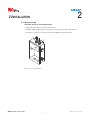
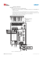
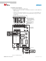
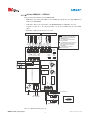
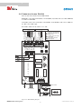
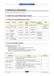
RM-2AC-IP
Installation and Operating Manual
© OSTI 0713 PN99740-0020 Rev. E
OMRON Scientific Technologies Inc.
0
© OSTI 0713 PN99740-0020 Rev..E
Table of Contents
Section 1—General System Description. . . . . . . . . . . . . . . . . . . . . . . . . . . . . . . . . . . . . . . . . . . . page 2
Section 2—Installation . . . . . . . . . . . . . . . . . . . . . . . . . . . . . . . . . . . . . . . . . . . . . . . . . . . . . . . . . page 3
2.1—Installation . . . . . . . . . . . . . . . . . . . . . . . . . . . . . . . . . . . . . . . . . . . . . . . . . . . . . . . . . . page 3
2.2—MiniSafe MS4800 . . . . . . . . . . . . . . . . . . . . . . . . . . . . . . . . . . . . . . . . . . . . . . . . . . . . . page 4
2.3—OptoShield OS3101 . . . . . . . . . . . . . . . . . . . . . . . . . . . . . . . . . . . . . . . . . . . . . . . . . . . page 5
2.4—F3SJ Light Curtain . . . . . . . . . . . . . . . . . . . . . . . . . . . . . . . . . . . . . . . . . . . . . . . . . . . . page 6
2.5—MiniSafe MS4600 / OF4600 . . . . . . . . . . . . . . . . . . . . . . . . . . . . . . . . . . . . . . . . . . . . . page 7
2.6—Perimeter Access PA4600. . . . . . . . . . . . . . . . . . . . . . . . . . . . . . . . . . . . . . . . . . . . . . . page 8
Section 3—Specifications and Additional Information . . . . . . . . . . . . . . . . . . . . . . . . . . . . . . . . page 9
3.1—System Specifications . . . . . . . . . . . . . . . . . . . . . . . . . . . . . . . . . . . . . . . . . . . . . . . . . . page 9
3.2—Spare Parts . . . . . . . . . . . . . . . . . . . . . . . . . . . . . . . . . . . . . . . . . . . . . . . . . . . . . . . . . page 10
3.3—Dimensional Drawings. . . . . . . . . . . . . . . . . . . . . . . . . . . . . . . . . . . . . . . . . . . . . . . . page 10
Section 4—Glossary of Terms. . . . . . . . . . . . . . . . . . . . . . . . . . . . . . . . . . . . . . . . . . . . . . . . . . . page 11
Section 5—Warranty and Additional Information . . . . . . . . . . . . . . . . . . . . . . . . . . . . . . . . . . . page 12
5.1—Warranty . . . . . . . . . . . . . . . . . . . . . . . . . . . . . . . . . . . . . . . . . . . . . . . . . . . . . . . . . . page 12
5.2—Repairs . . . . . . . . . . . . . . . . . . . . . . . . . . . . . . . . . . . . . . . . . . . . . . . . . . . . . . . . . . . page 12
5.3—Returns . . . . . . . . . . . . . . . . . . . . . . . . . . . . . . . . . . . . . . . . . . . . . . . . . . . . . . . . . . . page 12
Table of Figures
Figure 1-1—RM-2AC-IP Layout . . . . . . . . . . . . . . . . . . . . . . . . . . . . . . . . . . . . . . . . . . . . . . . . . page 2
Figure 2-1—Cable Strain Reliefs . . . . . . . . . . . . . . . . . . . . . . . . . . . . . . . . . . . . . . . . . . . . . . . . . page 3
Figure 2-2—MS4800 Wiring Diagram. . . . . . . . . . . . . . . . . . . . . . . . . . . . . . . . . . . . . . . . . . . . . page 4
Figure 2-3—OS3101 Wiring Diagram . . . . . . . . . . . . . . . . . . . . . . . . . . . . . . . . . . . . . . . . . . . . . page 5
Figure 2-4—F3SJ Wiring Diagram . . . . . . . . . . . . . . . . . . . . . . . . . . . . . . . . . . . . . . . . . . . . . . . page 6
Figure 2-5—MS/OF4600 Wiring Diagram . . . . . . . . . . . . . . . . . . . . . . . . . . . . . . . . . . . . . . . . . page 7
Figure 2-6—PA4600 Wiring Diagram . . . . . . . . . . . . . . . . . . . . . . . . . . . . . . . . . . . . . . . . . . . . . page 8
Figure 3-1—RM-2AC-IP Dimensional Drawings . . . . . . . . . . . . . . . . . . . . . . . . . . . . . . . . . . . page 10
OMRON Scientific Technologies Inc.
1
© OSTI 0713 PN99740-0020 Rev.E
1
1
1 G ENERAL S YSTEM D ESCRIPTION
+24VDC
0 VDC
CTL RET
MTS
CTL 2
CTL 1
AUX 2
COM +
COM -
START
AUX 1
EDM
OSSD 1
OSSD 2
0 VDC
+24VDC
The RM-2AC-IP is a resource module in a metal enclosure with an environmental rating of IP65. This
product can be used with the MS4800, F3SJ (PNP version only), OS3101, MS/OF4600, and PA4600.
The RM-2AC-IP provides power for safety devices with solid-state safety outputs and converts the
outputs of those devices to force-guided relay outputs. Two normally open (NO) and one normally
closed (NC) safety relay outputs and two normally closed (NC)/normally open (NO) auxiliary relay
outputs are provided. The two auxiliary outputs can be selected to accept NPN or PNP. Additionally,
the RM-2AC-IP serves as a central point for terminating all signals to and from a solid-state safety
device, including EDM (External Device Monitoring). The removable relay board facilitates
installation and servicing.
SW2
AUX
TB2
6
CTL RET
2
Auxiliary outputs
3
Removable relay board
4
Safety outputs
5
In-line fuse (replaceable)
6
Receiver and transmitter connections
1
NPN
YES
EXT
INT
TB3
NO
Configuration switches
a. EDM
i. INT: the relays on the relay board
will be monitored
ii. EXT: relays connected to the
outputs will be monitored via 2 NC
contacts in series across EDM and
0VDC on TB3.
b. AUX
i. PNP: when the safety device has
PNP auxiliary outputs
ii. NPN: when the safety device has
NPN auxiliary outputs
c. F3SJ
i. NO: an F3SJ is not being used.
ii. YES: an F3SJ is being used.
SW1
EDM
SW3
F3SJ
MTS
CTL 2
CTL 1
START
EDM
0 VDC
+24VDC
PNP
1
.
X
A
U
.O
K4
N
2
.C
N
.
6
TB
X
1
2
A
U
AC – DC POWER MODULE
. N
.O
K3
N
.
.C
B5
T
N.C.
N.O.1
TB1
5
N.O.2
K1
K2
3
O.S.S.D.
4
(L) Line (N) Neut
TB4
F1
Figure 1-1 RM-2AC-IP Layout
OMRON Scientific Technologies Inc.
2
© OSTI 0713 PN99740-0020 Rev..E
2
2 I NSTALLATION
2 . 1 I NS TAL LAT IO N
WARNING! In order to ensure IP65 protection:
•
Install cable strain relief (provided) at locations 1 and 2.
•
Install the gasketed plastic plug (provided) at location 2, when using an OS3101 Laser Scanner.
•
If locations 3, 4 and/or 5 are used, the user must provide IP65-rated cable strain reliefs.
1
2
5
4
3
Figure 2-1 Cable Strain Reliefs
OMRON Scientific Technologies Inc.
3
© OSTI 0713 PN99740-0020 Rev.E
2
2 . 2 M I NI S A FE M S 4 8 0 0
There are three slide switches inside the RM-2AC-IP:
•
EDM (SW1): select either internal (INT) or external (EXT). By default, this is set to INT. EDM must be
enabled on the MS4800.
•
AUX (SW2): The auxiliary output of the RM-2AC-IP needs to be configured based on the MS4800
being installed. If you are using the MS4800B or MS4800S, the AUX needs to be set to PNP. For an
MS4800A, the auxiliary output could be either PNP or NPN, depending on your configuration.
•
F3SJ (SW3): Make sure this switch is set to “NO”.
Brown
NOTE:
1 = NC switch to 0V shown. Other
configurations are possible. See
MS4800 manual
2 = MTS requires a NC switch. If
not used, install a jumper wire
between CTL RET and MTS on
TB3.
3 = Connection to Protective
Earth is required.
0 VDC
+24VDC
White
Blue
MTS/TEST
CTL RET
CTL 2
CTL 1
COM -
AUX 2
Black
Green
Green
COM +
Red
MS4800 Transmitter
Yellow
EDM
START
White
Pink
OSSD 2
AUX 1
Black
OSSD 1
Blue
+24VDC
0 VDC
Brown
MS4800 Receiver
Earth
CTL RET
CTL 2
CTL 1
START
EDM
0 VDC
+24VDC
TB2
MTS/TEST
SW2
AUX
PNP
NPN
SW1
EDM
SW3
F3SJ
NO YES
INT
EXT
TB3
.N
ED 1 ED 2
.
.C
.O
K4
.O
.
K3
N
TB4
O.S.S.D.
(L) Line (N) Neut
N.C.
N.O.1
N.O.2
K1
K2
5
TB
TB1
F1
3
Protective
Earth
.N
6
TB
.
C
AUX1
2
AC DC POWER MODULE
MTS
1
AUX2
N
START
To PLC Control
ED2
Fuse
Line Voltage
100 - 240 VAC
SUPPRESSOR
ED1
To Machine Control
ED1 ED2
SUPPRESSOR
Control Voltage
Figure 2-2 MS4800 Wiring Diagram
OMRON Scientific Technologies Inc.
4
© OSTI 0713 PN99740-0020 Rev..E
2 . 3 O PTO S HI ELD O S 3 1 0 1
There are three slide switches inside the RM-2AC-IP:
•
EDM (SW1): select either internal (INT) or external (EXT). By default, this is set to INT. EDM must be
enabled on the OS3101.
•
AUX (SW2): The Auxiliary output of the RM-2AC-IP needs to be configured based on the OS3101
being installed. Refer to the model number of OS3101. Look for the designation of either “NP” or “PN”
in the model number. A “NP” refers to NPN and the “PN” refers to PNP output.
•
F3SJ (SW3): Make sure this switch is set to “NO”.
Shield
Brown
NOTE:
1 = NC switch to 0V shown. Other
configurations are possible. See
MS4800 manual
2 = Zone select
= Connection to Protective
3 Earth is required.
0 VDC
+24VDC
MTS/TEST
Brown
Org/white
Org/black
Black
CTL 2
CTL RET
Red/Black
Pink
Gray
EDM
START
COM +
COM AUX 2
CTL 1
Yellow
Red
Blue
White
+24VDC
0 VDC
OSSD 1
OSSD 2
AUX 1
White
OS3101 Power I/O Cable
Earth
+24VDC
TB2
0 VDC
EDM
START
CTL 1
CTL 2
CTL RET
MTS/TEST
SW2
AUX
PNP NPN
SW1
EDM
F3SJ
SW3
NO YES
INT EXT
TB3
.
.C
ED 1 ED 2
.N
.O
K4
6
TB
.
.C
2
AUX2
N
START 1
AC – DC POWER MODULE
.N
.O
TB4
O.S.S.D.
F1
3
Protective (L) Line (N) Neut
Earth
N.C.
TB1
N.O.2
N.O.1
K1
K2
5
TB
AUX1
K3
N
To PLC Control
ED2
To Machine Control
Fuse
Line Voltage
100 – 240 VAC
SUPPRESSOR
ED1
ED1 ED2
SUPPRESSOR
Control Voltage
Figure 2-3 OS3101 Wiring Diagram
OMRON Scientific Technologies Inc.
5
© OSTI 0713 PN99740-0020 Rev.E
2
2 . 4 F 3 SJ L I GH T C U RT AI N
There are three slide switches inside the RM-2AC-IP:
•
EDM (SW1): select either internal (INT) or external (EXT). By default, this is set to INT. EDM must be
enabled on the F3SJ.
•
AUX (SW2): Check the F3SJ model number for an “N” or a “P”, where “N” designates NPN and “P”
designates PNP. Set the auxiliary output slider switch in the RM-2AC-IP to the appropriate setting for
your F3SJ system.
•
F3SJ (SW3): Make sure this switch is set to “YES”.
F3SJ Transmitter
NOTE:
1 = Mute select active. The red
wire is connected to CTL2 if
there is muting; otherwise,
connect the red wire to AUX2.
Connect mute sensors to CTL1
and CTL2 on TB3.
Yellow
White
Red
Green
Blue
Brown
+24VDC
0 VDC
OSSD 1
OSSD 2
AUX 1
EDM
START
COM +
COM AUX 2
CTL 1
CTL 2
1
2 = External Test Function. If
used, connect NO switch to
MTS/Test on TB3
3 = Connection to Protective
Earth is required.
CTL RET
MTS/TEST
0 VDC
+24VDC
White
Yellow
Red
Pink
Gray
Gray
Pink
Brown
Blue
Green
F3SJ Receiver
Earth
SW2
AUX
MTS
/TEST
CTL RET
EDM
START
CTL 1
CTL 2
+24VDC
0 VDC
TB2
TB3
SW3
F3SJ
PNP NPN
SW1
EDM
NO YES
INT EXT
ED1 ED2
6
TB
.
.C
AUX2
1
2
.N
TB4
O.S.S.D.
F1
3
Protective
(L) Line (N) Neut
Earth
N.C.
TB1
N.O.2
K1
K2
5
TB
AUX1
.O
N
K3
AC – DC POWER MODULE
TEST
N
1
K4
MUTE2
.
.C
.N
.O
N.O.1
RESET
MUTE1
Refer to the F3SJ
user’s manual for
more information.
To PLC Control
ED2
Fuse
Line Voltage
100 – 240 VAC
To Machine Control
SUPPRESSOR
ED1
ED1 ED2
SUPPRESSOR
Control Voltage
Figure 2-4 F3SJ Wiring Diagram
OMRON Scientific Technologies Inc.
6
© OSTI 0713 PN99740-0020 Rev..E
2 . 5 M I NI S AFE M S 4 6 0 0 / O F 4 6 0 0
There are three slide switches inside the RM-2AC-IP:
•
EDM (SW1): select either internal (INT) or external (EXT). By default, this is set to INT. EDM must be
enabled on the MS/OF4600.
•
AUX (SW2): Refer to the model number of the MS4600/OF4600. On a MS4600, look for the
designation of either “N” or “P” in the model number. An “N” refers to NPN and the “P” refers to PNP
output.
•
F3SJ (SW3): Make sure this switch is set to “NO”.
MS4600/OF4600 Receiver
MS4600/OF4600 Transmitter
NOTE:
= NC switch to 0V shown. Other
1 configurations are possible. See
MS4600 manual
2 = For MTS, requires NC switch
pulled to 0VDC
CTL 1
CTL 2
CTL RET
MTS/TEST
0 VDC
+24VDC
Black
Blue
Brown
White
Shield
White
Shield
COM AUX 2
EDM
START
COM +
OSSD 2
AUX 1
0 VDC
OSSD 1
+24VDC
Brown
Orange
Yellow
Violet
Pink
Gray
3
3 = For MTS, connect the black wire
of the transmitter cable to CTL
RET, connect the blue wire to
MTS/TEST.
4 = Connection to Protective
Earth is required.
Earth
+24VDC
0 VDC
EDM
START
CTL 1
CTL 2
CTL RET
MTS
/TEST
SW2
AUX
TB2
PNP NPN
SW1
EDM
SW3
F3SJ
NO YES
INT EXT
TB3
.
.C
ED 1 ED 2
.O
AUX2
K4
5
.N
.O
K3
N
N.C.
N.O.2
N.O.1
TB4
O.S.S.D.
K2
TB
TB1
F1
4
Protective
(L) Line (N) Neut
Earth
6
TB
.
.C
K1
AC – DC POWER MODULE
2
AUX1
N
START 1
MTS
.N
To PLC Control
ED2
Fuse
Line Voltage
100 – 240 VAC
SUPPRESSOR
ED1
To Machine Control
ED1 ED2
SUPPRESSOR
Control Voltage
Figure 2-5 MS/OF4600 Wiring Diagram
OMRON Scientific Technologies Inc.
7
© OSTI 0713 PN99740-0020 Rev.E
2
2 . 6 P E RIM E TER A C CE SS P A 4 6 0 0
There are three slide switches inside the RM-2AC-IP:
EDM (SW1): select either internal (INT) or external (EXT). By default, this is set to INT. EDM must
be enabled on the PA4600.
AUX (SW2): Refer to the model number of the PA4600. On the PA4600 a “NP” refers to NPN and
the “PN” refers to PNP output.
F3SJ (SW3): Make sure this switch is set to “NO”.
Blue
Brown
White
Black
NOTE:
= NC switch to 0V shown. Other
1 configurations are possible. See
PA4600 manual
2 = For MTS, requires NC switch
pulled to 0VDC
3 = Connection to Protective
Earth is required.
CTL 1
CTL 2
CTL RET
MTS/
TEST
0 VDC
+24VDC
COM AUX 2
Green
Pink
Gray
Green
PA4600 Transmitter
EDM
START
COM +
White
+24VDC
0 VDC
OSSD 1
OSSD 2
AUX 1
Brown
Red
Yellow
Blue
PA4600 Receiver
Earth
SW3
F3SJ
PNP NPN
SW1
EDM
NO YES
INT EXT
MTS
/TEST
CTL RET
EDM
START
CTL 1
CTL 2
TB2
+24VDC
0 VDC
SW2
AUX
TB3
.C
.O
AUX2
K4
5
.N
K3
N
TB4
N.C.
O.S.S.D.
TB1
N.O.2
K1
K2
TB
F1
3
Protective
(L) Line (N) Neut
Earth
6
TB
.
.C
.O
N.O.1
AC – DC POWER MODULE
2
AUX1
N
START 1
MTS
.
.N
ED 1 ED 2
To PLC Control
Fuse
ED2
Line Voltage
100 – 240 VAC
SUPPRESSOR
ED1
To Machine Control
ED1 ED2
SUPPRESSOR
Control Voltage
Figure 2-6 PA4600 Wiring Diagram
OMRON Scientific Technologies Inc.
8
© OSTI 0713 PN99740-0020 Rev..E
3 S PECIFICATIONS
AND
A DDITIONAL
3
I NFORMATION
3 . 1 S YST EM S P EC IFI CA TI ON S
Performance
Max. Response Time
10 ms NO, 20 ms NC plus maximum response time of safety
device being used
Indicators
3 green LEDs: Power, OSSD1, OSSD2
Electrical
Input Voltage
100 to 240 VAC, 50-60 Hz
Input Power
not more than 0.6/0.4A on 100 to 240 VAC
Internal Power Supply
24VDC ± 5% output at 1A
Safety Relay Outputs
Two NO and one NC force-guided contacts rated:
AC1: 250 VAC / 6A (resistive load)
DC1: 30 VDC / 6A (resistive load)
AC15: 240 VAC / 2A (inductive load)
DC13: 24 VDC / 1A (inductive load)
Auxiliary (Non-Safety) Relay
Outputs
Two NO/NC contacts. 250VAC / 5A, 30VDC / 5A (resistive load);
250VAC / 2A, 30VDC / 3A (inductive load)
EDM (MPCE
The safety output of the RM-2AC-IP unit must be monitored by the
light curtain via the EDM line
Cable Connections / Terminal
Blocks / Wire Size
3 rows of removable terminal blocks; 3 non-removable terminal
blocks; 14 AWG max. wire
Environmental
Enclosure Rating
IP65
Operating Temperature
0 to 55°C (32° to 131°F)
Relative Humidity
95% maximum, non-condensing
Storage Temperature
- 25°C to 75°C
Vibration
10 Hz to 55 Hz, 1 octave/minute, 20 sweeps for each of 3 axes
(per IEC 60068-2-6)
Shock
10 g, 16 ms, 1000 for each of 3 axes (per IEC 60068-2-29)
Mechanical
Enclosure
Polyurethane painted steel
Mounting
0.30 in. (7.6 mm) diameter mounting holes
Dimensions
2.0 mm thick, 25 cm by 17 cm by 7 cm.
Conformity/Approvals
CE approved and conforms to IEC 61496-1, EN 954-1, EN 602041, EN 50178, and Type 4 safety category (only when used with an
Omron STI Type 4 safety light curtain with EDM enabled).
CSA approved
SIL-3 (IEC 61508) when used with an Omron STI SIL-3 product
RoHS compliant
Table 3-1 RM-2AC-IP Specifications
OMRON Scientific Technologies Inc.
9
© OSTI 0713 PN99740-0020 Rev.E
3
3 . 2 S P ARE P AR TS
Model Number
Decscription
SP-RM2AP-RLY
Relay Board
SP-TB3
Terminal blocks (auxiliary)
SP-TB6
Terminal blocks (safety)
FUSE-T1.25A-SB
Fuse (250 mA)
SP-CRG
Cable Strain Relief (for use with Omron STI cables)
SP-PLG
Gasketed Plastic Plug (for use with the OS3101)
3 . 3 D IM EN SI ON AL D R AW IN G S
RM-2AC-IP CONTROLLER
(POWER SUPPLY/ LOGIC) ENCLOSURE BOX
1.33
33.7
1.73
43.9
1.73
43.9
1.42
36.1
.843
21.4
TOP VIEW
.875
22.2
f
KNOCKOUT
f
THRU HOLE (2 PLCS)
SEALED BY LIQUID-TITE CABLE GLANDS
7.40
188.0
1.69
MIN.
42.9
.30
DIA MTG HOLES (8)
7.6
4.00
101.6
RM-2AC-IP
11.5
293
MIN.
9.60
243.8
5.30
134.6
6.55
166.4
.78
19.8
FRONT VIEW
LEFT SIDE VIEW
2.05
52.1
BACK VIEW
RIGHT SIDE VIEW
.875/1.13
22.2/28.7
f
10.10
256.5
10.80
274.3
11.16
284.0
KNOCKOUT
COMBO (3 PLCS)
2.76
70.1
1.33
33.8
1.45
36.8
1.70
43.2
DIMENSIONS:
INCHES (+\-.01)
mm (+\-.3)
BOTTOM VIEW
Figure 3-1 RM-2AC-IP Dimensional Drawings
OMRON Scientific Technologies Inc.
10
© OSTI 0713 PN99740-0020 Rev..E
4 G LOSSARY
OF
4
T ERMS
EDM: External Device Monitoring. also known as MPCE (Machine Primary Control Element). This is
the electrically powered element that directly controls the normal operation of a machine such that it is
the last element (in time) to function when machine operation is to be initiated or arrested. Monitoring
of light curtains to machine control interface is necessary to detect malfunction within interface that
would prevent a stop signal from reaching the machine controller. EDM is required for control
reliability.
MTS: Machine Test Signal. A feature which allows a machine controller to simulate an interruption of
the sensing field.
Muting: A control reliable method of allowing the complete bypass or disabling of the light curtain’s
sensing field or stop signal to the protect machine during the non-hazardous(usually upstroke) portion
of the machine cycle. Generally accomplished by either of two methods.
NC: Normally closed
NO: Normally open
OSSD: Output Signal Switching Device. The component of a safety light curtain connected to the
machine control system which, when the light curtain is actuated during normal operation, responds by
going to the off-state.
OMRON Scientific Technologies Inc.
11
© OSTI 0713 PN99740-0020 Rev.E
4
5 W ARRANTY AND A DDITIONAL I NFORMATION
5 . 1 W A RR AN TY
Omron STI warrants its products to be free from defects of material and workmanship and will,
without charge, replace or repair any equipment found defective upon inspection at its factory, or other
designated point provided the equipment has been returned, transportation prepaid, within one year
from date of installation and not to exceed 18 months from date of factory shipment. Any software
products are provided “AS IS” and “WITH ALL FAULTS” and Omron STI makes no warranty that
the operation of software products will be uninterrupted or error free. THE FOREGOING
WARRANTY IS IN LIEU OF AND EXCLUDES ALL OTHER WARRANTIES NOT EXPRESSLY
SET FORTH HEREIN, WHETHER EXPRESSED OR IMPLIED BY OPERATION OF LAW OR
OTHERWISE, INCLUDING BUT NOT LIMITED TO, ANY IMPLIED WARRANTIES OF
MERCHANTABILITY, NON-INFRINGEMENT OR FITNESS FOR A PARTICULAR PURPOSE.
No representation or warranty, express or implied, made by any sales representative, distributor, or
other agent or representative of Omron STI which is not specifically set forth herein shall be binding
upon Omron STI. Omron STI shall not be liable for any incidental or consequential damages, losses or
expenses directly or indirectly arising from the sale, handling, improper application or use of the goods
or from any other cause relating thereto and Omron STI's liability hereunder, in any case, is expressly
limited to the repair or replacement (at Omron STI's option) of goods.
Warranty is specifically at the factory. Any on-site service will be provided at the sole expense of the
buyer at standard field service rates.
All associated equipment must be protected by properly rated electronic/electrical protection devices.
Omron STI shall not be liable for any damage due to improper engineering or installation by the
purchaser or third parties. Proper installation, operation and maintenance of the product becomes the
responsibility of the user upon receipt of the product. Returns and allowances must be authorized by
Omron STI in advance. Omron STI will assign a Returned Goods Authorization (RGA) number which
must appear on all related papers and the outside of the shipping carton. All returns are subject to final
review by Omron STI. Returns are subject to restocking charges as determined by Omron STI.
5 . 2 R EP AI RS
Omron STI offers product repair service at our factory. If you need repairs made to any Omron STI
product, contact our Customer Service Department at 1-800-556-6766.
5 . 3 R ETU RN S
Whenever you return a product to Omron STI (even if the product is in warranty) please contact our
Customer Service Department (1-800-556-6766) and request a Returned Goods Authorization number
(RGA). Goods that are returned for credit are subject to final review by Omron STI and are subject to
restocking charges as determined by Omron STI.
OMRON Scientific Technologies Inc.
12
© OSTI 0713 PN99740-0020 Rev..E
OMRON AUTOMATION AND SAFETY • THE AMERICAS HEADQUARTERS • Chicago, IL USA • 847.843.7900 • 800.556.6766 • www.omron247.com
OMRON CANADA, INC. • HEAD OFFICE
Toronto, ON, Canada • 416.286.6465 • 866.986.6766 • www.omron247.com
OMRON ARGENTINA • SALES OFFICE
Cono Sur • 54.11.4783.5300
OMRON ELECTRONICS DE MEXICO • HEAD OFFICE
México DF • 52.55.59.01.43.00 • 01-800-226-6766 • [email protected]
OMRON CHILE • SALES OFFICE
Santiago • 56.9.9917.3920
OMRON ELECTRONICS DE MEXICO • SALES OFFICE
Apodaca, N.L. • 52.81.11.56.99.20 • 01-800-226-6766 • [email protected]
OTHER OMRON LATIN AMERICA SALES
54.11.4783.5300
OMRON ELETRÔNICA DO BRASIL LTDA • HEAD OFFICE
São Paulo, SP, Brasil • 55.11.2101.6300 • www.omron.com.br
OMRON EUROPE B.V. • Wegalaan 67-69, NL-2132 JD, Hoofddorp, The Netherlands. • +31 (0) 23 568 13 00 • www.industrial.omron.eu
Authorized Distributor:
Automation Control Systems
• Machine Automation Controllers (MAC) • Programmable Controllers (PLC)
• Operator interfaces (HMI) • Distributed I/O • Software
Drives & Motion Controls
• Servo & AC Drives • Motion Controllers & Encoders
Temperature & Process Controllers
• Single and Multi-loop Controllers
Sensors & Vision
• Proximity Sensors • Photoelectric Sensors • Fiber-Optic Sensors
• Amplified Photomicrosensors • Measurement Sensors
• Ultrasonic Sensors • Vision Sensors
Industrial Components
• RFID/Code Readers • Relays • Pushbuttons & Indicators
• Limit and Basic Switches • Timers • Counters • Metering Devices
• Power Supplies
Safety
• Laser Scanners • Safety Mats • Edges and Bumpers • Programmable Safety
Controllers • Light Curtains • Safety Relays • Safety Interlock Switches
F92I-E-01
07/13
Note: Specifications are subject to change.
Printed on recycled paper.
© 2014 Omron Electronics LLC
Printed in U.S.A.