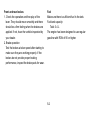
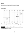
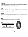
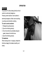
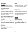
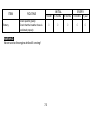
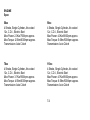
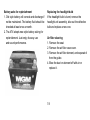
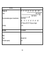
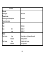
1
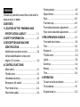
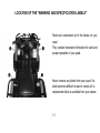
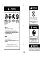
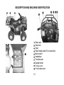
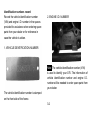
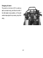
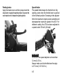
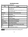
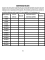
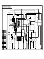
USER MANUAL
READ THIS MANUAL CAREFULLY.
It contains important safety information.
□50 □70 □90 □110
INTRODUCTION
This manual will provide you with a clear understanding of the details and operation of this vehicle.
This manual includes all of the necessary safety information. It provides information necessary to
ride your vehicle and also includes basic service and inspection procedures.
AN IMPORTANT SAFETY MESSAGE:
● READ THIS MANUAL CAREFULLY AND COMPLETELY BEFORE OPERATING YOUR
VEHICLE. MAKE SURE YOU UNDERSTAND ALL INSTRUCTIONS.
● PAY CLOSE ATTENTION TO THE WARNING AND CAUTION LABELS ON THE VEHICLE.
● NEVER OPERATE AN ATV WITHOUT PROPER TRAINING OR INSTRUCTION.
IMPORTANT MANUAL INFORMATION:
FAILURE TO FOLLOW THE WARNINGS CONTAINED IN THIS MANUAL CAN RESULT IN
SERIOUS INJURY OR DEATH.
Particularly important information is distinguished in this manual by the following notations:
ATTENTION: The Safety Alert Symbol means ATTENTION! BE ALERT! YOUR SAFETY IS
INVOLVED!
WARNING: Failure to follow WARNING instructions could result in severe injury or death to the
vehicle operator, a bystander or a person inspecting or repairing the vehicle.
CAUTION: A CAUTION indicates special precautions that must be taken to avoid damage to the
vehicle.
NOTE:
A NOTE provides key information to make procedures easier or clearer.
IMPORTANT NOTICE
This vehicle is designed and manufactured for OFF-ROAD use only. It is illegal and unsafe to
operate this machine on any public street, road or highway.
This vehicle complies with all applicable OFF-ROAD noise level and spark arrester laws and
regulations in effect at the time of manufacture.
Please check your local riding laws and regulations before operating this machine.
! WARNING
Indicates a potential hazard that could result in
serious injury or death.
CONTENTS:
1 LOCATION OF THE "WARNING AND
SPECIFICATION LABELS"… … … … ....... 1-1
2 SAFETY INFORMATION........................... 2-1
3 DESCRIPTION AND MACHINE
IDENTIFICATION...................................... 3-1
Identification numbers record.................... 3-2
Vehicle identification number and
engine I.D. number.................................... 3-2
4 CONTROL FUNCTIONS
Main switch................................................ 4-1
Throttle lever.............................................. 4-1
Handlebar switches................................... 4-2
Emergency kill switch................................ 4-3
Front brake lever....................................... 4-4
Rear brake pedal....................................... 4-4
Parking brake............................................ 4-5
Speed limiter.............................................. 4-5
Seat.......................................................... 4-6
Fuel tank cap............................................ 4-6
Front shock absorber adjustment............. 4-7
Rear shock absorber adjustment.............. 4-7
5 PRE-OPERATION CHECKS..................... 5-1
Front and rear brakes................................ 5-2
Fuel........................................................... 5-2
Engine oil................................................... 5-3
Throttle lever.............................................. 5-4
Lights......................................................... 5-4
Switches.................................................... 5-4
Battery… … … … … … … … … … … … ............ 5-4
Tires.......................................................... 5-4
6 OPERATION
To start out and accelerate… … … … … … ... 6-1
To decelerate............................................. 6-1
Engine break-in......................................... 6-2
Parking...................................................... 6-2
Parking on a slope..................................... 6-2
7 PERIODIC SERVICE................................. 7-1
Engine....................................................... 7-4
Engine oil................................................... 7-5
Idle speed adjustment............................... 7-6
Throttle lever adjustment........................... 7-6
Brake adjustment-rear brake..................... 7-7
Brake lever lubrication............................... 7-7
Fuse replacement...................................... 7-8
Battery asks for replenishment.................. 7-9
Replacing the headlight bulb..................... 7-9
Air filter cleaning… … … … … … … … … … … 7-9
8 SPECIFICATIONS..................................... 8-1
9 MAINTENANCE RECORD........................ 9-1
LOCATION OF THE "WARNING AND SPECIFICATION LABELS"
Read and understand all of the labels on your
quad.
They contain important information for safe and
proper operation of your quad.
Never remove any labels from your quad. If a
label becomes difficult to read or comes off, a
replacement label is available from your dealer.
1-1
1
○
2
○
3
○
4
○
1-2
SAFETY INFORMATION
TO DRIVE AN ATV IS A SERIOUS MATTER AND CAN BE HAZARDOUS TO OPERATE. An ATV
handles differently from other vehicles including motorcycles and cars. A collision or rollover can
occur quickly, even during routine maneuvers such as turning and riding on hills or over obstacles, if
you fail to take proper precautions.
SEVERE INJURY OR DEATH can result if you do not follow these instructions:
● Read this manual and all labels carefully and follow the operating procedures described.
● Never operate an ATV without proper training or instruction.
●A child under 16 years old should never operate an ATV.
● Never carry a passenger on an ATV.
● Always avoid operating an ATV on any paved surfaces, including sidewalks, driveways, parking
lots and streets.
● Never operate an ATV on any public street, road or highway nor a dirt or gravel one.
● Never operate an ATV without wearing an approved motorcycle helmet that fits properly. You
should also wear eye protection (goggles or face shield), gloves, boots, long-sleeved shirt or
jacket, and long pants.
● Never consume alcohol or drugs before or while operating this ATV.
●Never operate at speeds too fast for your skills or the conditions.
2-1
●Never attempt wheelies, jumps, or other stunts.
●Always inspect your ATV each time you use it to make sure it is in safe operating condition.
●Always follow the inspection and maintenance procedures and schedules described in
this manual.
● Always keep both hands on the handlebars and both feet on the footboards of the ATV during
operation.
●Never operate the ATV in fast flowing water or in water deeper than 25 cm (10 in.).
●Always use the size and type of tires specified in this manual. Always maintain proper tire pressure
as described in this manual.
●Never modify the ATV through improper installation or use of accessories.
●Never exceed the stated load capacity for an ATV. Cargo should be properly distributed and
securely attached. Reduce speed and follow instructions in this manual for carrying cargo or
pulling a trailer. Allow greater distance for braking while transporting cargo.
! WARNING
Always turn off the engine when refueling.
Don’
t start or run the engine in a closed area to avoid potential hazard.
2-2
DESCRIPTION AND MACHINE IDENTIFICATION
1
○
2
○
3
○
4
○
5
○
6
○
7
○
8
○
9
○
10
○
Rear rack
Seat lock
Seat
Rear brake pedal (Foot operation)
Main switch
Handlebar
Throttle lever
Speed limiter
Parking switch
Front brake lever
3-1
Identification numbers record
Record the vehicle identification number
(VIN) and engine I.D. number in the spaces
provided for assistance when ordering spare
parts from your dealer or for reference in
case the vehicle is stolen.
2. ENGINE I.D. NUMBER
1. VEHICLE IDENTIFICATION NUMBER
Note: The vehicle identification number (VIN)
is used to identify your ATV. The information of
vehicle identification number and engine I.D.
number will be needed to order spare parts from
your dealer.
The vehicle identification number is stamped
on the front side of the frame.
3-2
CONTROL FUNCTIONS
Main switch
Functions of the respective switch positions are
as follows:
On: Engine can be started only at this position.
Off: All electrical circuits are switched off. The
key can be removed in this position.
Throttle Lever
Once the engine is running, movement of the
throttle lever will increase the engine speed.
Regulate the speed of the engine by varying
the throttle position. Because the throttle is
spring-loaded, the engine will decelerate, and
the engine will return to an idle any time your
finger is removed from the throttle lever.
Before starting the engine, check the throttle to
be sure it is operating smoothly. Make sure it
returns to the idle position as soon as the lever
is released.
4-1
Handlebar switches
Start switch
The starter motor cranks the engine when this
switch is pushed.
CAUTION:
See starting instructions prior to starting engine.
Lights switch
Turn the switch on for front light and taillight
(option accessory).
1. Engine stop switch (Red)
2. Start switch
3. Lights switch (Black) (option)
Engine stop switch
The engine stop switch controls the ignition
and can be used at all times to stop the engine,
especially in an emergency. The engine will not
start or run when the engine stop switch is
turned to “ ”. When starting the engine, the
function button should be at “ ”position.
CAUTION:
Do not use the headlight with the engine turned
off for more than 10 minutes. The battery may
discharge to the point that the starter motor will
not operate properly. If this should happen,
remove the battery and recharge it, replace if
necessary.
4-2
Emergency kill switch
This switch is in the front of ATV, to which an
adult can attach string, and follow the child. If
the child needs to stop suddenly, or if the adult
wants to stop engine for any reason, just pull the
string.
4-3
Front brake lever
The brake lever is located on the right side of
the handlebar. Pull down on the lever to apply
the front brake.
Rear brake pedal
The brake pedal is located on the right side of
the frame. Step on the lever to apply the rear
brake.
4-4
Parking brake
Apply the brake lever and then press down the
stop-button to apply the parking brake. Squeeze the
rear brake lever to release the parking brake.
Speed limiter
The speed limiter keeps the throttle from fully
opening, even when the throttle lever is pushed
to the furthest position. Screwing in the adjuster
limits the maximum engine power available and
decreases the maximum speed of the ATV. For
children’
s safety, this ATV has been adjusted to
a speed under 35 km/h (22 mph).
WARNING:
Do not turn the speed adjuster out more than
12 mm (0.47 in.).
Always make sure the throttle lever free play
is 3~5 mm (0.12~0.20 in.).
4-5
Seat
To remove the seat, pull the seat lock lever
upward and pull up the seat at the rear.
Fuel tank cap
Remove the fuel tank cap by turning it
counterclockwise.
Automotive gasoline with octane number of 90
or higher may be used.
After refueling, be sure to tighten the tank cap
firmly.
To install the seat, insert the lobe on the seat
front into the receptacle on the frame and push
down the seat at the rear.
4-6
Front shock absorber adjustment
The spring preload can be adjusted to suit the
vehicle’
s load and riding conditions.
Spring preload adjustment:
To increase the spring preload, turn the
adjuster in direction a.
To decrease the spring preload, turn the
adjuster in direction b.
Rear shock absorber adjustment
The spring preload can be adjusted to suit the
vehicle’
s load and riding conditions.
Spring preload adjustment:
To increase the spring preload, turn the
adjuster in direction a.
To decrease the spring preload, turn the
adjuster in direction b.
Standard position: A
A--Minimum (Soft) E--Maximum (Hard)
Standard position: A
Warning:
Uneven adjustment on different sides can cause
poor handling and loss of stability.
4-7
PRE-OPERATION CHECKS
Before using this ATV, check the following points:
ITEM
ROUTINE
Check operation, free play. Check the combination of the brake lever,
brake cable and pad.
Brakes
If the brake pad is becoming worn, please replace with a new one
before use of the vehicle.
Parking brake
Check operation, condition and cable free play.
Check fuel level.
Fuel tank
Fill with fuel if necessary.
Check oil level.
Engine oil
Fill with oil if necessary.
Throttle
Check for proper throttle cable operation.
Wheels and tires
Check tire pressure, wear and damage.
Fittings and fasteners
Check all fittings and fasteners.
Lights
Check for proper operation if the lights have been installed.
Check fluid level.
Battery
Fill with distilled water if necessary.
ATTENTION: Always check each item in the above list prior to operating your ATV.
5-1
Front and rear brakes
1. Check the operation and free play of the
lever. They should move smoothly and there
should be a firm feeling when the brakes are
applied. If not, have the vehicle inspected by
your dealer.
2. Brake operation
Test the brakes at slow speed after starting to
make sure they are working properly. If the
brakes do not provide proper braking
performance, inspect the brake pads for wear.
Fuel
Make sure there is sufficient fuel in the tank.
Fuel tank capacity:
Total: 3.4 L
The engine has been designed to use regular
gasoline with RON of 90 or higher.
5-2
Engine oil
Make sure the engine oil is at the specified level. Add oil if necessary.
Recommended oil:
Recommended engine oil classification: API Service SE, SF, SG type or higher.
ATTENTION: Do not add any anti-friction modifier to ensure proper clutch function.
Oil quantity in engine: 0.9 L (0.24 gal.).
5-3
Throttle lever
Check to see that the throttle lever operates correctly. It must open smoothly and spring back to idle
position when released. Repair if necessary for proper operation.
Lights
If you have installed lights, check the headlight and taillight to make sure they are in working
condition. Repair if necessary for proper operation.
Switches
Check the operation of the headlight switch, engine stop switch and any other switches. Repair if
necessary for proper operation.
Battery
Check battery power; change the battery if electric power is getting poor.
Tires
1. Recommended tires for this ATV listed below:
Front
160/80-7
Rear
160/80-7
5-4
2. The tires should be set to the recommended pressure.
Recommended tire pressure:
Front 0.6-0.7 kgf/cm 2
Rear 0.7 kgf/cm2
Check and adjust tire pressures when the tires are cold.
Tire pressures must be equal on both sides.
3. Tire pressure below the minimum specified could cause the tire to dislodge from the rim under
severe riding conditions.
Minimum tire pressure:
Front 0.55 kgf/cm 2
Rear 0.55 kgf/cm 2
4. Use no more than the following pressures when seating the tire beads.
Front 2.5 kgf/cm 2
Rear 2.5 kgf/cm 2
Higher pressures may cause the tire to burst. Inflate the tires very slowly and carefully.
Fast inflation could cause the tire to burst.
5. Tire wear limit
When the tire groove decreases to 3 mm (0.12 in.) due to wear, replace the tire.
5-5
OPERATION
WARNING:
To operate ATV without being familiar with all
controls is extremely dangerous.
Freezing control cables in cold weather is
extremely dangerous. Make sure everything
is working smoothly before starting.
To start out and accelerate:
1. Release the parking brake.
2. Open the throttle gradually.
3. Once the vehicle has attained adequate
speed, release the throttle lever.
4. Open the throttle gradually.
To decelerate:
When slowing down or stopping, release the
throttle and apply the brakes smoothly and
evenly.
6-1
Engine break-in
ATTENTION: The first 20 hrs for engine
break-in is very important; never exceed the
running condition listed below:
0 ~ 10 hours:
Avoid continuous operation above half throttle.
Allow a cooling off period of five to ten minutes
after every hour of operation.
Vary the speed of the vehicle from time to time.
Do not operate it at one set throttle position.
10 ~ 20 hours:
Avoid prolonged operation above 3/4 throttle.
Rev the vehicle freely, but do not use full throttle
at any time.
After break-in:
Avoid prolonged full throttle operation. Vary
speeds occasionally.
Parking
When parking, stop the engine. Turn the fuel
cock to “OFF”and apply the parking brake.
Parking on a slope
Avoid parking on slopes. If you must park on an
incline, apply the parking brake, and block the
wheels with rocks or other objects.
ATTENTION:
MAXIMUM LOADING LIMIT
Vehicle loading limit (total weight of cargo, rider
and accessories, and tongue weight): 90 kg
(198 lbs.).
6-2
PERIODIC SERVICE
PERIODIC SERVICE/LUBRICATION
ITEM
Valves
Spark plug
Air filter
Carburetor
Cylinder head
cover breather
system
Exhaust system
ROUTINE
INITIAL
1 month
Check valve clearance.
Adjust if necessary.
Check condition.
Adjust gap and clean.
Replace if necessary.
Clean.
Replace if necessary.
Check idle speed/starter operation.
Adjust if necessary.
Check breather hose for cracks or
damage.
Replace if necessary.
Check leakage.
Retighten if necessary.
Replace gasket if necessary.
3 months
○
○
○
EVERY
6 months
6 months
1 year
○
○
○
○
○
○
Every 20~40 hours
(more often in wet or dusty areas)
○
7-1
○
○
○
○
○
○
○
○
○
ITEM
Fuel line
Engine oil
Engine oil strainer
Brake
Tires
Wheel bearings
Steering system
ROUTINE
INITIAL
1 month
Check fuel hose for cracks or
damage.
Replace if necessary.
Check oil level weekly.
Replace.(Warm up engine before
draining.)
Clean.
Check operation every time
before driving.
Correct if necessary.
Check pressure and wear.
Replace if damaged.
Check bearing assembly for
looseness/damage.
Replace if damaged.
Check operation, replace if
damaged.
Check toe-in, adjust if necessary.
3 months
6 months
6 months
1 year
○
○
○
○
○
○
○
○
○
○
○
○
○
○
○
○
○
○
○
○
○
○
○
○
○
○
○
○
7-2
EVERY
○
ITEM
Battery
ROUTINE
INITIAL
EVERY
1 month
3 months
6 months
6 months
1 year
○
○
○
○
○
Check specific gravity.
Check that the breather hose is
positioned properly.
WARNING:
Never service the engine while still running!
7-3
ENGINE
Spec:
50cc
4 Stroke, Single Cylinder, Air-cooled
12v, C.D.I., Electric Start
Max Power: 2.0Kw/7500rpm approx.
Max Torque: 2.5Nm/6000rpm approx.
Transmission: Auto Clutch
90cc
4 Stroke, Single Cylinder, Air-cooled
12v, C.D.I., Electric Start
Max Power: 4.0Kw/8000rpm approx.
Max Torque: 5.6Nm/6000rpm approx.
Transmission: Auto Clutch
70cc
4 Stroke, Single Cylinder, Air-cooled
12v, C.D.I., Electric Start
Max Power: 3.7Kw/8500rpm approx.
Max Torque: 4.5Nm/6000rpm approx.
Transmission: Auto Clutch
110cc
4 Stroke, Single Cylinder, Air-cooled
12v, C.D.I., Electric Start
Max Power: 4.7Kw/8500rpm approx.
Max Torque: 6.5Nm/6000rpm approx.
Transmission: Auto Clutch
7-4
Engine oil
1. Engine oil level measurement
a. Place the vehicle on a level surface.
b. Warm up the engine for several minutes and
stop it.
c. Wait a few minutes until the oil level settles
before checking.
d. Remove the dipstick and wipe it off with a
clean rag. Insert the dipstick in the filler hole
without screwing it in.
e. Remove the dipstick and inspect the oil level.
f. The oil level should be between the maximum
and minimum marks. If the level is low, add oil
to raise it to the proper level.
2. Engine oil replacement and oil strainer
cleaning
a. Place the vehicle on a level surface.
b. Warm up the engine for several minutes and
stop it.
c. Place a container under the engine.
d. Remove the dipstick and drain plug to drain
the oil.
CAUTION:
Be sure no foreign material enters the
crankcase.
7-5
Idle speed adjustment
NOTE: A diagnostic tachometer must be used
for this procedure.
1. Start the engine and warm it up for a few
minutes at approximately 1,000 to 2,000
r/min. Occasionally rev the engine to
4,000 to 5,000 r/min. The engine is warm
when it quickly responds to the throttle.
2. Connect the tachometer and set the idle
to the specified idling speed by adjusting
the throttle stop screw. Turn the screw
into increase engine speed, and out to
decrease engine speed.
SPECIFIED IDLE SPEED: 1700 rpm±100
Throttle lever adjustment
NOTE: Adjust the engine idling speed before
adjusting the throttle lever free play.
1. Loosen the locknut.
2. Turn the adjusting bolt until the throttle
lever free play is 3~5 mm (0.12~0.20 in).
3. Tighten the locknut.
1. Locknut
2. Adjusting bolt
a. 3 ~ 5 mm (0.12 ~ 0.20 in.)
7-6
Brake adjustment – rear brake
The rear brake lever free play should be
20~25 mm (0.80~1.0 in.). If the free play is
incorrect, adjust it as follows:
1. Raise the rear side of vehicle to make rear
tires leave from the ground.
2. Turn the rear wheels and turn the bolts and
nuts on these 2 positions to adjust the caliper
only with a suitable brake condition.
3. Tighten the nuts and test the adjustment
result, if it’
s still not adequate, do the same
process again.
Brake lever lubrication
Lubricate the pivot of each lever and pedal.
Please use SAE 10W30 motor oil.
7-7
Fuse replacement
If the fuse is blown, turn off the main switch
and install a new fuse of the specified
amperage. Then turn on the switches. If the
fuse immediately blows again, consult your
dealer. Specified fuse: 7 A/250 V.
1. main fuse
WARNING:
Never use an improper fuse.
An improper fuse can cause damage to the
electrical system which could lead to a fire.
CAUTION:
To prevent accidental short circuit, turn off the
main switch when checking or replacing a fuse.
7-8
Battery asks for replenishment
1. Old style battery will corrode and discharge if
not be maintained. The battery fluid should be
checked at least once a month.
2. The ATV adopts new style battery asking for
replenishment. Just enjoy its easy use
and sound performance.
Replacing the headlight bulb
If the headlight bulb is burnt, remove the
headlight unit assembly, take out the defective
bulb and replace a new one.
Air filter cleaning
1. Remove the seat.
2. Remove the air filter case cover.
3. Remove the air filter element, and separate it
from the guide.
4. Blow the dust on element off with air or
replace it.
7-9
SPECIFICATIONS
MODEL
Dimensions
Overall length
Overall width
Overall height
Minimum ground clearance
Basic Weight
Without oil
Engine
Engine type
Displacement
Starting system
Lubrication system
1420mm
860mm
910mm
160mm
92 KGS
4-stroke, single cylinder, air-cooled
50cc 39×41.4mm
70cc 47×41.4mm
90cc 47×49.5mm
110cc 52.4×49.5mm
Electric
Pressuring splash
8-1
MODEL
Quantity
0° 10° 30° 50° 70° 90° 100° 130℉
SAE 20W40
SAE 10W30
SAE 5W30
-20° -10° 0° 10° 20° 30° 40° 50℃
API Service SE, SF, SG type or higher
0.9 L
Air filter
Dry element
Fuel
Type
Fuel tank capacity
Unleaded fuel
3.4 L
Engine oil
Type
Recommended engine oil classification:
8-2
MODEL
Chassis
Frame type
Transmission
Secondary reduction system
Transmission type
Tire
Type
Size
front
rear
Brake
Front brake
type
operation
Rear brake
type
operation
Steel tube
Automatic
Tubeless
160/80-7
160/80-7
Drum brake or Hydraulic disc brake
Hand operation
Hydraulic disc brake
Foot operation
8-3
MODEL
Suspension
Front suspension
Rear suspension
Shock absorber
Front shock absorber
Rear shock absorber
Electrical
Ignition system
Generator system
Battery type/voltage, capacity
Double swing-arm
Single swing-arm
Coil spring/Oil damper
Coil spring/Oil damper
C.D.I.
Magneto
12V, 4A (50/70/90)
8-4
12V, 7A (110)
MAINTENANCE RECORD
Copies of work orders and/or receipts for parts you purchase and install will be required to document
maintenance done in accordance with the warranty. The chart below is printed only as a reminder to
you that the maintenance work is required. It is not acceptable proof of maintenance work.
MAINTENANCE
SERVICING DEALER
DATE OF
REMARKS
MILEAGE
NAME AND ADDRESS
SERVICE
INTERVAL
1 month
3 months
6 months
12 months
18 months
24 months
30 months
36 months
42 months
48 months
54 months
60 months
89-1
FA-D50-B Circuit Diagram
B/W
B/W
Br/W
R
B/W
G
R
Y
B/W
Ignition
switch
B Foot brake
switch
Annunciator
Starter
Gr
R
Horn
switch
R
Colour
B
Black
G
Green
R
Red
W
White
Y
Yellow
Bl
Blue
Br
Brown
Gr
Gray
B/W
Black/White
Bl/W
Blue/White
Bl/Y
Blue/Yellow
Br/W
Brown/White
G/Y
Green/Yellow
R/B
Red/Black
R/Y
Red/Yellow
Gr
G/Y
Hand brake
switch
Note
R/Y
Br/W
Change
switch
R/Y
G/Y
Gr
Horn
Bl/W
Bl/Y
Ignition
Bl
Y
W Starter
motor
R/B
Br/W
Ignition
coil
Taillight
B/W
Magneto
G
Br
Br/W
G
G
Headlight
Gr
Fog light
Gr