1
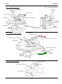
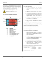
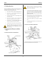
S-Series
_________________________________________________________________________
SM-54
Instruction Manual
_________________________________________________
MANUFACTURER:
DISTRIBUTER:
SCHUSTER Transferpressen GmbH
Fritz-Reichle-Ring 20
78315 Radolfzell
GERMANY
FON:
+49-7732-30279-10
FAX:
+49-7732-30279-13
E-MAIL: [email protected]
WEB:
www.schuster-transferpressen.de
Tel
1300 196 156
[email protected]
Street 24/25 Ingleston Road, Tingalpa QLD. 4173 Australia
Webwww.colourcomponents.com.au
Tel 1300 196 156 www.colourcomponents.com.au
S-Series
ENGLISH
__________________________________________________________________________
SM-54
Instruction Manual
1 Safety Advice .................................................................................................................................................................12
1.1 Manual Convention ................................................................................................................................................12
1.2 Important Security Advices ....................................................................................................................................12
1.3 Working with the Transfer Press ............................................................................................................................12
2 Check Shipment ..............................................................................................................................................................13
3 Assembling and Bringing into Service ...........................................................................................................................13
4 Settings ...........................................................................................................................................................................13
4.1 Height Adjustment for Work Plate .........................................................................................................................13
4.2 Set Pressure ............................................................................................................................................................14
4.3 Time and Temperatur Controller ............................................................................................................................14
4.3.1 Set Temperatur ............................................................................................................................................14
4.3.2 Set Printing Time ........................................................................................................................................14
5 Printing Operation ..........................................................................................................................................................15
6 Exchange Heat Element and Work Plate ........................................................................................................................15
6.1 Build in and Extend a Heat Element ......................................................................................................................15
6.2 Build in and Extend a Work Plate ..........................................................................................................................15
7 Maintenance....................................................................................................................................................................16
8 Problem Solving .............................................................................................................................................................16
9 Technical Data ................................................................................................................................................................17
The SCHUSTER Transferpressen GmbH takes no responsibility for damages arising from misuse, reparations, and modifications which where carried out
by third, not authorized parties, as well as for damages arising from non observance of the instruction manual. This handbook was constructed with great
care, a liability for small negligent mistakes, for example printing error, however are excluded.
The SCHUSTER Transferpressen GmbH takes no responsibility for damages or errors which arise from the use of accessory or spare parts which are not
original pdeviceucts of SCHUSTER Transferpressen GmbH.
Below SCHUSTER Transferpressen GmbH is identified as the manufacturer.
Copyright © 2010 SCHUSTER Transferpressen GmbH. All rights reserved
.
- 10 -
SM-54
ENGLISH
Abb. 1: Vorderansicht SM-54
Abb. 2: Rückansicht SM-54
Schließhebel
Maschinenkopf
Schwenkhebel
Heizplatte
Instrumentengehäuse
Arbeitsplatte
Klemmgriff
Kurbel zur Höhenverstellung
Abb. 3: Zusammenbau der SM-54
TransportSicherungsschraube
Schraube M6x12 + Scheibe
Gummipuffer + Scheiben
Schließhebel
Schraube M6x18 + Scheibe
Stützfuß
Abb. 4: Instrumentengehäuse
Heizplatten-Stecker
Hauptschalter
Zeit-& Temperatursteuerung
Sicherungshalter
- 11 -
ENGLISH
SM-54
current of all connected equipment does not
exceed the allowed power supply of the
connected electrical outlet.
1 Safety Advice
Never try to maintenance the device on your
own.
Read through following advices before bringing the
transfer press into service. It is necessary to consider all
warnings and advices indicated on the transfer press.
To ensure safe operations of the transfer press,
the operator has to make sure that nonauthorized people neither work on the machine,
nor set the machine into operation, or perform
any other operations on the machine.
1.1 Manual Convention
You can find this symbol in particular on
important safety advices in this instruction
manual, in which you will be advised about the
right handling of the transfer press. It is
necessary to pay attention to these advices.
Non-observance can lead to injuries of the user.
All operations on the transfer press can only be
accomplished by specialised staff who gained
an appropriate instruction or training.
General legal and other binding regulations for
accident
prevention
and
environmental
protection are to be considered in addition to
this instruction manual.
Security advices which are marked with this
symbol, it’s necessary to pay attention to. In
case of non observance, burns of the user may
occur. You also can find this symbol marked on
some parts on the transfer press.
A symbol like this advices you, that through
crushing danger of injuries exists. You also can
find this symbol marked on parts of the transfer
press.
1.3 Working with the Transfer Press
Look out not to touch the lower part of the heat
element while the press is in service, otherwise
burns may occur. Please also note that there is
still a danger to suffer burns even after turning
off the transfer press for a longer time.
1.2 Important Security Advices
This transfer press presents dangers if used
inappropriately, or when used for a non intended use. For
this reason, read carefully all of the following advices:
The case of the heat element will also be heating
up; so be careful.
The transfer press may only be used for
printings on pressure- and heat resistant
materials. Every exceeding use is seen as not
intended. If still used for non intended service,
the manufacturers will not be liable for the
resulting
damages.
Unauthorized
reconstructions and modifications are not
permitted, because they will interfere with the
security and the service of the machine.
During the service of the press, and especially
during the start of the transfer press, never put
your hand between the work plate and the heat
element, or the transfer press. Furthermore,
make sure that no other person can reach the
transfer press.
2 Check Shipment
Don’t insert any objects through the case notch.
Also make sure that no fluid will reach the
transfer press and the heat element.
SM-54 with a single
sliding table
with a double sliding
table
1 x silicone foam pad
2 x silicone foam pads
1 x protective cover
2 x protective cover
Watch out not to damage the power plug.
1 x hexagon wrench
button
1 x hexagon wrench
button
If you connect the transfer press over an
extension cable, please make sure that the
overall nominal current (of all connected
equipment) does not exceed the allowed current
load. Further make sure that the overall nominal
1 x instruction manual
1 x instruction manual
The used mains voltage has to be the same as
the stated mains voltage on the type plate of the
transfer press.
- 12 -
SM-54
ENGLISH
3 Assembling and Bringing Into Service
1.
Unpack the transfer press.
2.
Bring the transfer press to it’s location of
service. Only use the assembled transport
device to move the press. Make sure that no
flammable or heat-sensitive materials or
equipment are in immediate vicinity of the
transfer press.
3.
4.
Remove the transport device. It is very
important to keep them, because the transfer
press can ONLY be moved through these
transport devices. In particular; faults which
will appear when trying to lift the transfer press
up on other parts than the transfer devices, will
be exempted from this warranty. It is especially
unacceptable, to lift the transfer press at the
sliding table or at the heat element. When you
assemble the transport devices, make sure you
plumb in the fixing screws tightly.
5.
Connect the power plug with an electrical outlet
and connect the compressed air pipe to the
compressed air filter (see page 11, Fig. 2 and 4).
6.
Switch on the power switch to start the transfer
press.
7.
The transfer press will be ready for operations
now.
4 Settings
4.1 Height Adjustment for Work Plate
Remove the corrugated-head screws on the
sliding table. Keep these as well for a further
transport to secure the sliding table against
slipping.
1
3
2
1.
The first step will be to loose the locking of the
height adjustments. To do so, turn the clip
handle to the left.
2.
Now turn the work plate in clockwise direction
to lower it, or in anticlockwise direction to raise
it.
3.
When you reached your desired height, turn the
clip handle to the right to lock the height
adjustment.
The gap between the undersurface of the heat
element and the upper surface of the article to
be printed on, should be 15 – 25 mm. Is the gap
bigger/higher than 25 mm; the transfer press
will automatically cancel the printing process
for technical reasons, and the heat element will
go back into its original position.
4.2 Set Pressure
You can adjust the pressure with the pressure regulator;
the manometer in the control panel serves as a control for
your changes.
- 13 -
ENGLISH
SM-54
The first step to change the pressure will be to pull out
the pressure regulator, then turn the pressure regulator to
the right, to increase the pressure, to the left to reduce it.
After you adjusted the desired pressure, push the
pressure regulator back in to set the pressure.
4.3.1 Set Temperature
1.
To set the temperature; push the button
“temperature“ once; the first cypher will start
flashing.
2.
Adjust the desired value with the „upwards“
button.
3.
To change the value of the second cypher, push
the button „to the right”; and the second cypher
will start flashing. Use the same procedure to
adjust the value.
4.
To change the third cypher; use the same
process like for the second cypher.
5.
Push the button „temperature” to save the
settings, as well as to leave the adjustment
mode.
Usual values for sublimation prints: 3 – 5 bar.
Maximum allowed pressure: 6 bar.
4.3 Time and Temperature Controller
7
1
4
6
5
3
2
The light-emitting diode will flash “heating“, as long as
the temperature set point is not reached yet. After heating
up, the light-emitting diode will flash „O.K.“ after the
transfer press reached the desired temperature.
8
Pos.
1.
2.
3.
4.
5.
6.
7.
8.
Recommended temperature values: 180 – 200 °C
Definition
4.3.2 Set Printing Time
button „temperature“
button „time“
button „to the right“
button „upwards“
Light-emitting diode „heating“
Light-emitting diode „O.K.“
Display „temperature“
Display „time“
Two different printing times can be adjusted:
1.
Push the button „time“, and hold it. In the
display „time“ (lower display) “t1” (1. time set
point) and “t2” (2. time set point) will flash for
about one second each.
2.
To adjust the desired time set point: Release the
button „time“, when your desired time set point
(t1. or t2.) is flashing up in the display. Now
only the first cypher should be flashing.
3.
Set the desired value with the button “upwards”.
4.
To change the second and third cypher, push the
button „to the right“. It will flash up. Set the
value like you did with the first cypher.
If you push the button „time“; settings will be saved and
you will leave the adjustment mode.
Acceptable values:
Usual printing time:
- 14 -
1. time set point:
0-399 sec.
2. time set point:
0-60 sec.
45 – 70 sec.
SM-54
ENGLISH
5 Printing Operation
Before you start to extend the heat element,
assure yourself that the heat element is cooled
down to room temperature.
After you adjusted your settings and the temperature was
reached (the light-emitting diode “O.K.” will flash) - you
can begin with your printing operations.
1.
At first remove the heat element plug. To do so;
you first of all have to loosen the corrugatedhead screw of the heat element plug with a
phillips screwdriver. Remove the heat element
plug from the outlet.
2.
Now you have to loosen both retaining screws
of the heat element with a 13-way spanner, and
screw it out for approximately 3-4 mm.
1.
If you have an SM-54, pull the sliding table out.
2.
If you have a , pull the double sliding table to
the left or right until it blocks.
3.
Arrange the item and the corresponding artwork
on the work plate.
4.
If you have an SM-54, push the sliding table
back into the transfer press until it blocks.
3.
Lift the heat element up, and pull it towards
you.
5.
If you have a , pull the double sliding table
towards the opposite side until it blocks.
4.
To build in a heat element, do the same process
in reversed order.
6.
Confirm both starter buttons and the same time.
7.
The heat element will lower and start the
operation. After the printing time is over, the
heat element will rise automatically and you
will hear a beep.
6.2 Build In and Extend a Work Plate
6 Exchange Heat Element and Work
Plate
6.1 Build In and Extend a Heat Element
Heizplatten-Stecker
Halte-Schrauben
Loose both retaining screws on the underside of the work
plate, then just pull the plate out towards you.
Halte-Schraube
- 15 -
ENGLISH
SM-54
8 Problem Solving
Problem
Transfer press does not work after
pushing the start button
After the printing process started,
the heat element lowers but returns
immediately into is original
position.
Work plate is twisting
Reason
Removal
1. Compressed air pipe is not
connected.
2. Compressor is turned off
3. Pressure regulator is closed
4. Sliding table is not in end
position
5. Start buttons didn’t get pushed at
the same time
6. Pushed emergency stop
Work plate was set up to low/ the
gap between heat element and
work plate is too big.
Height is not adjusted
insufficient locked in place.
- 16 -
or
Connect the compressed air pipe with the
compressed air filter (Ch. 3)
Turn on the compressor
Turn the pressure regulator to the left
(Ch. 4.2)
Push the sliding table until it blocks
(Ch.5)
Push the start buttons both at the same
time (Ch. 5)
Open the emergency stop
Raise the work plate, clearance max. 25
mm (Ch. 4.1)
Arrange the work plate and lock the right
height adjustment through turning the clip
handle to the right - until the work plate is
not twistable anymore. (Ch. 4.1)
SM-54
ENGLISH
9 Technical Data
SM-54
External Dimensions L x W x H
920 x 478 x 528 mm
880 x 1150 x 528 mm
Weight
80 kg
Voltage
230 V
Max. current consumption
9A
Max. heating power
2000 W
Temperature
Up to 210°C
1. time domain: 0 - 399 sec.
Time of pressure
2. time domain: 0 - 60 sec
Max. pressure
6 bar
Max. pressure at 6 bar
17 kN ≙ 1,7 t
Max. surface pressure at 6 bar on a pressure
surface of 40 x 50 cm
8,7 N/cm²
Max. height of the article to be printed on
ca. 50 mm
17