1
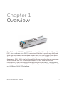
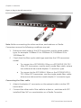
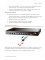
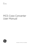
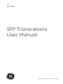
GE
Security
SFP Transceivers
User Manual
P/N 1069181 • REV 1.0 • ISS 22FEB10
Copyright
© 2010 GE Security, Inc.
This document may not be copied in whole or in part or otherwise
reproduced without prior written consent from GE Security, Inc.,
except where specifically permitted under US and international
copyright law.
Disclaimer
The information in this document is subject to change without notice.
GE Security, Inc. (“GE Security”) assumes no responsibility for
inaccuracies or omissions and specifically disclaims any liabilities,
losses, or risks, personal or otherwise, incurred as a consequence,
directly or indirectly, of the use or application of any of the contents
of this document. For the latest documentation, contact your local
supplier or visit us online at www.gesecurity.com.
This publication may contain examples of screen captures and
reports used in daily operations. Examples may include fictitious
names of individuals and companies. Any similarity to names and
addresses of actual businesses or persons is entirely coincidental.
Trademarks and
patents
Intended use
FCC compliance
GE and the GE monogram are trademarks of General Electric
Company. Other trade names used in this document may be
trademarks or registered trademarks of the manufacturers or
vendors of the respective products.
Use this product only for the purpose it was designed for; refer to the
data sheet and user documentation for details. For the latest product
information, contact your local supplier or visit us online at
www.gesecurity.com.
This equipment has been tested and found to comply with the limits
for a Class B digital device, pursuant to part 15 of the FCC Rules.
These limits are designed to provide reasonable protection against
harmful interference in a residential installation. This equipment
generates, uses and can radiate radio frequency energy and, if not
installed and used in accordance with the instructions, may cause
harmful interference to radio communications. However, there is no
guarantee that interference will not occur in a particular installation.
If this equipment does cause harmful interference to radio or
television reception, which can be determined by turning the
equipment off and on, the user is encouraged to try to correct the
interference by one or more of the following measures:
•
Reorient or relocate the receiving antenna.
•
Increase the separation between the equipment and receiver.
•
Connect the equipment into an outlet on a circuit different from
that to which the receiver is connected.
•
Consult the dealer or an experienced radio/TV technician for
help.
Regulatory
information
Manufacturer
N4131
GE Security, Inc.
HQ and regulatory responsibility:
GE Security, Inc., 8985 Town Center Parkway,
Bradenton, FL 34202, USA
EU authorized manufacturing representative:
GE Security B.V., Kelvinstraat 7,
6003 DH Weert, The Netherlands
2002/96/EC (WEEE directive): Products marked with this symbol
cannot be disposed of as unsorted municipal waste in the European
Union. For proper recycling, return this product to your local supplier
upon the purchase of equivalent new equipment, or dispose of it at
designated collection points. For more information see:
www.recyclethis.info.
Contact information
For contact information see our Web site: www.gesecurity.com.
For contact information see our Web site: www.gesecurity.eu.
Content
Chapter 1 Overview 1
Model List 2
Checklist 2
Introduction 2
Installing SFP modules 3
Appendix A Fiber Optic Cable Parameters 7
SFP Transceivers User Manual
i
Chapter 1
Overview
The GE Security SFP1000 and SFP100 family of Small Form Factor Pluggable
(SFP, also known as mini-GBIC) Transceiver Modules is specifically designed
for a high performance integrated duplex data link over single mode optical
fiber. These transceiver modules are compliant with the SFP Multisource
Agreement (MSA). With the hot plug ability, these modules offer an easy way
to be installed into SFP MSA compliant ports at any time without the
interruption of the host equipments operating online. The SFP Transceivers
can be installed into any of GE Security Switch products with the 100Base-FX
or 1000Base-SX/LX SFP interface.
SFP Transceivers User Manual
1
Chapter 1: Overview
Model List
The GE SFP1000/SFP100 Transceiver family comes with one of the following
models.
SFP module List
Model
SFP1000SX-220
SFP1000LX-10Km
Interface
Speed
Fiber connector and distance
1000Base-SX 1000Mbps LC, Multi-Mode (850nm) -220m/550m
1000Base-LX 1000Mbps
LC, Single Mode (1310nm) – 10km
SFP100FX1310-TSC-2Km
100Base-FX
100Mbps
LC, Multi-Mode (1310nm) -2km
SFP100FX1310-TSC-20Km
100Base-FX
100Mbps
LC, Single Mode (1310nm) – 20km
Checklist
Your SFP Transceiver box should contain the following items:
•
The SFP transceiver module
•
This User's manual
If any item is missing or damaged, please consult the dealer from whom you
purchased you SFP Transceiver module.
Introduction
1000Base-SX / LX SFP Mini-GBIC Modules - SFP1000SX-220, SFP1000LX10Km
Features:
2
•
Complies with the IEEE 802.3z Gigabit Ethernet standard
•
1 X 1000Mbps fiber port
SFP Transceivers User Manual
Chapter 1: Overview
•
Plug and Play Installation
•
SFP1000SX-220 provides distance up to 220m over 62.5/125µm
fiber cable and 550m over 50/125µm fiber cable
•
SFP1000LX-10Km provides distance up to 10km over 9/125µm
single mode fiber cable
100Base-FX SFP Mini-GBIC Modules - SFP100FX1310-TSC-2Km /
SFP100FX1310-TSC-20Km
Features:
•
Complies with IEEE 802.3u Fast Ethernet standard
•
1 x 100Mbps fiber port
•
Plug and Play Installation
•
SFP100FX1310-TSC-2Km provides distance up to 2km over
62.5/125µm multi-mode fiber cable
•
SFP100FX1310-TSC-20Km provides distance up to 20km over
9/125µm single mode fiber cable
Installing SFP modules
The section describes how to insert an SFP transceiver into an SFP slot.
The SFP transceivers are hot pluggable and hot swappable. You can plug-in
and out the transceiver from any SFP port without having to power down the
Switch/Media Converter. As Figure 1 shows.
SFP Transceivers User Manual
3
Chapter 1: Overview
Figure 1: Plug-in the SFP transceiver
Note: Before connecting the other switches, workstations or Media
Converters ensure the following conditions are met.
1.
Make sure both sides of the SFP transceiver are the same media
type, for example: 100Base-FX to 100Base-FX, 1000Base-SX to
1000Base-SX.
2.
Check that the fiber-optic cable type matches the SFP transceiver
model.
•
To connect to a SFP1000SX-220m or a SFP100FX1310-TSC2Km SFP transceiver, use the multi-mode fiber cable- where
one side must be a male duplex LC connector type.
•
To connect to the SFP1000LX-10km or the SFP100FX1310TSC-20Km SFP transceiver, use the single-mode fiber cablewhere one side must be a male duplex LC connector type.
Connecting the Fiber cable
4
1.
Attach the duplex LC connector on the network cable into the SFP
transceiver.
2.
Connect the other end of the cable to a device - switches with SFP
installed, fiber NIC on a workstation or a Media Converter.
SFP Transceivers User Manual
Chapter 1: Overview
3.
Check that the LNK/ACT LED on the SFP slot of the switch/converter.
Ensure that the SFP transceiver is operating correctly.
4.
Check the Link mode of the SFP port. If the link failed. Set the Link
mode to "1000 Force" or "100 Force" if needed.
Removing the module
1.
Make sure that there is no network activity by checking with the
network administrator. Or through the management interface of the
switch/converter (if available) to disable the port in advance.
2.
Remove the Fiber Optic Cable gently.
3.
Turn the handle of the MFB module to horizontal.
4.
Pull out the module gently through the handle.
Figure 2: Pullout the transceiver
Note: Never pull out the module without pull the handle or the push bolts on
the module. Pulling out the module with too much force could damage the
module and SFP module slot of the Managed Industrial Switch.
SFP Transceivers User Manual
5
Chapter 1: Overview
6
SFP Transceivers User Manual
Appendix A
Fiber Optic Cable
Parameters
The wiring details are shown below:
Standard
Fiber Type
Cable Specification
1000Base-SX (850nm)
Multi-mode
50/125 μm or 62.5/125μm
1000Base-LX (1310nm)
Single mode
9/125μm
Multi-mode
50/125μm or 62.5/125μm
Single mode
9/125μm
100Base-FX (1310nm)
SFP Transceivers User Manual
7