1
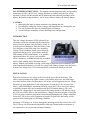
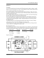
DP10 & DP20 User’s Manual
B R A N D
Models DP10 & DP20 Series
Low Voltage Disconnects
User’s Manual
Rev. 1.1
October 31, 2007
For Sales, Support and Service
phone: 407-331-4793
fax: 407-331-4708
website: www.xenotronix.com
email: [email protected]
Xenotronix/TLI, Inc.
2541 Tracy Road
Toledo, Ohio 43619
Phone: 419-666-6982
Fax: 419-666-6534
Xenotronix/TLI, Inc.
1
DP10 & DP20 User’s Manual
Warranty
Seller warrants that its products ("Product(s)") will meet the specifications set forth in its catalog
from time to time, unless the Buyer is notified otherwise prior to delivery. Seller will, without
charge, repair or provide a replacement for any of the Products which prove to be defective in
materials or workmanship within one (1) year from the date of shipment ("Warranty Period").
If, within the Warranty Period, Buyer discovers a defect in materials or workmanship which
interferes with the operation of any Product, Buyer must promptly notify Seller, in writing, of such
defect. Seller's sole obligation to Buyer under this Warranty is to repair and correct any defect in
material or workmanship, or provide a replacement Product to Buyer. Seller's decision with
respect to the applicability of this Warranty to any defect shall be final and conclusive. Seller
reserves the right to require Buyer, at Buyer's sole cost and expense, to return any defective
Product, including any alterations made thereto, F.O.B. Seller's factory in Ohio.
Seller does not warrant against abrasion, corrosion or erosion. Seller shall not be liable to Buyer or
to any other person for work done or repairs made, to remedy any defect, by any person who is not
an authorized representative of Seller, unless Seller's written consent is first obtained by Buyer.
This Warranty does not apply to, and is rendered null and void by, any Product which, after
leaving Seller's manufacturing plant: (a) is repaired or altered without Seller's prior written
approval; (b) is the subject of improper storage, installation or operation; (c) is the subject of
intentional or negligent misuse, misapplication, neglect or accident; or (d) is not used, repaired or
altered in accordance with Seller's written instructions.
Seller expressly reserves the right to declare this Warranty null and void upon Buyer's failure to
make full and timely payments with respect to any Products purchased by Buyer from Seller, in
which event all of Seller's obligations, and Buyer's rights, under this Warranty, shall immediately
terminate. SELLER DISCLAIMS THE IMPLIED WARRANTY OF MERCHANTABILITY
AND FITNESS FOR A PARTICULAR PURPOSE, AND ANY IMPLIED WARRANTIES
ARISING FROM COURSE OF PERFORMANCE, COURSE OF DEALING, OR USAGE OF
TRADE. SELLER SHALL NOT BE LIABLE TO BUYER OR ANY OTHER PARTY UNDER
THIS WARRANTY FOR DIRECT, SPECIAL, CONSEQUENTIAL, INDIRECT OR
INCIDENTAL DAMAGES OF ANY KIND.
Notice to the User
The information contained in this manual is believed to be correct. However,
Xenotronix/TLI, Inc. assumes no responsibility for any inaccuracies therein.
Information in this manual is subject to change without notice. No part of this manual may
be reproduced or transmitted in any form, electronic or mechanical, for any purpose, without
the express written permission of Xenotronix/TLI, Inc.
Copyright © 2007 Xenotronix/TLI, Inc. All rights reserved.
Xenotronix/TLI, Inc.
2
DP10 & DP20 User’s Manual
TABLE OF CONTENTS
Models DP10 & DP20 Low Voltage Disconnect – User’s Manual
Precautions . . . . . . . . . . . . . . . . . . . . . . . . . . . . . . . . . . . . . . . . . . . . . . . . . . 1
Introduction . . . . . . . . . . . . . . . . . . . . . . . . . . . . . . . . . . . . . . . . . . . . . . . . . 1
Product Photo . . . . . . . . . . . . . . . . . . . . . . . . . . . . . . . . . . . . . . . . . . . . . . . . 1
Installation . . . . . . . . . . . . . . . . . . . . . . . . . . . . . . . . . . . . . . . . . . . . . . . . . . 1
Hook-Up . . . . . . . . . . . . . . . . . . . . . . . . . . . . . . . . . . . . . . . . . . . . . . . . . . . . 2-3
Terminals . . . . . . . . . . . . . . . . . . . . . . . . . . . . . . . . . . . . . . . . . . . . . 2
Recommended Wire Sizes . . . . . . . . . . . . . . . . . . . . . . . . . . . . . . . . 2
Hook-Up Diagram . . . . . . . . . . . . . . . . . . . . . . . . . . . . . . . . . . . . . . 2
Hook-Up Summary. . . . . . . . . . . . . . . . . . . . . . . . . . . . . . . . . . . . . . 3
Operating Instructions . . . . . . . . . . . . . . . . . . . . . . . . . . . . . . . . . . . . . . . . . 3
LVD Operation Notes and Tips . . . . . . . . . . . . . . . . . . . . . . . . . . . . . . . . . . 3-4
Custom Units . . . . . . . . . . . . . . . . . . . . . . . . . . . . . . . . . . . . . . . . . . . . . . . . 5
Battery Charger Specifications . . . . . . . . . . . . . . . . . . . . . . . . . . . . . . . . . . . 6
Dimensions . . . . . . . . . . . . . . . . . . . . . . . . . . . . . . . . . . . . . . . . . . . . . . . . . . 6
Xenotronix/TLI, Inc.
3
DP10 & DP20 User’s Manual
SAVE THESE INSTRUCTIONS - This manual contains important safety and operating
instructions for DP10 & D20 Low Voltage Disconnects. Before using the low voltage
disconnect, please read this manual and all instructions and cautionary markings on the
battery, the product using the battery, and if using a battery charger, the battery charger.
CAUTION:
o Miswireing the input or output connectors may damage the unit.
o Exceeding the ratings for current, voltage, and temperature may damage the unit.
o Use only as directed to prevent personal injury and damage.
o Avoid touching components as static discharge may damage them.
INTRODUCTION
This low voltage disconnect (LVD) is basically an
electronic switch that automatically disconnects the
battery from the product using the battery (load). It
is used to prevent damage to either the battery, from
over discharge, or the load, from a low operating
voltage. These conditions usually occur in backup
applications during an AC power failure with the
load running off the backup battery, or in portable
applications where AC power is not available.
Alarm versions are available that provide an audible
and/or visual warning before disconnecting the
battery. Models are available covering a wide range of lead-acid, nickel-cadmium, and
nickel-metal-hydride batteries. If used in a system with a battery charger, once the battery
is about 50% charged, the LVD will automatically reconnect the battery to the load.
INSTALLATION
Due to wire resistance, the voltage at the load will be lower than at the battery. This
effect is more pronounced at higher currents, with smaller gage wires, and with longer
wire runs. Because of this, location plays a roll in how to best implement the low voltage
disconnect in your application. If the main purpose of using the LVD is to protect the
battery, while obtaining the maximum discharge, locate the LVD as close to the battery
as possible (shortest wire runs located between the LVD and the battery). This will
minimize the voltage drop in the leads between the battery and the LVD and the voltage
the LVD sees will be closer to the actual battery voltage. If the main purpose of using the
LVD is to protect sensitive equipment from potentially damaging low voltage conditions,
locate the LVD as close to the equipment as possible. In both cases the battery will be
protected from a damaging over discharge condition.
Mount the LVD using a no. 8 screw through the mounting hole in the center of the LVD.
The LVD may also be mounted using double-sided tape. Mount inside an enclosure or
use a protective cover to prevent mechanical damage.
Xenotronix/TLI, Inc.
4
DP10 & DP20 User’s Manual
HOOK-UP
Terminals:
The +BATT terminal is used to power the LVD and monitor the battery voltage. A small
gage wire may be used; however, if the +LOAD terminal is used to connect the load, then
a wire sized for the full load current must be used.
The –BATT terminal is used to power the LVD, monitor the battery voltage, and is also
the path for the full load current to flow into the LVD from the battery. This wire must be
sized for the full load current.
The –LOAD terminal is the path for the full load current to flow out of the LVD and into
the load. This wire must be sized for the full load current.
The +LOAD terminal is an optional connection point for connecting the positive load
wire if the positive battery terminal is not convenient. If used, it will draw the full load
current from the battery through the +BATT terminal and both wires must be sized for
the full load current.
The BEEPER header is for connecting the optional remote beeper accessory if using a
remote alarm version of the LVD. Small gage wires may be used.
The LED header is for connecting the optional remote LED accessory if using an alarm
version of the LVD. Small gage wires may be used.
Recommend Wire Sizes:
Wire manufacturers rate the current carrying capacity of wire based on a safe temperature
rise for the insulation. However, these ratings do not account for the voltage drop caused
by high currents and the resistance of the wire. We recommend the following wire gages:
Load Current
Wire Size
Load Current
Wire Size
0 to 4 Amps
18 AWG
11 to 15 Amps
12 AWG
4 to 7 Amps
16 AWG
15 to 20 Amps
10 AWG
7 to 10 Amps
14 AWG
Hook-Up Diagram:
LOAD
NEG
BATT
LOAD
BATT
POS
INCR
OPTIONAL
DECR
BATTERY
CHARGER
Xenotronix/TLI, Inc.
5
DP10 & DP20 User’s Manual
Hook-Up Summary:
To summarize, the +BATT and -BATT terminals on the LVD must be attached to the
battery to power the circuit. The negative load wire must be attached to the –LOAD
terminal on the LVD. The positive load wire is normally attached directly to the positive
battery terminal (preferred for high current applications); however, it may be connected
to the +LOAD terminal on the LVD if it is more convenient. If the +LOAD terminal is
used, the full load current will flow through the wire connecting the +BATT terminal to
the battery, so that wire must be sized to handle the full load current as well. For the best
performance, the shortest length and largest gage hook-up wires should be used.
OPERATING INSTRUCTIONS
Once the LVD is properly connected to the load and battery, operation is automatic.
When first attached to the battery, the LVD circuit defaults to a connected status and the
–BATT and –LOAD terminals are connected to each other. If the battery is discharged
down to the disconnect voltage, the LVD will wait 3-seconds to make sure it is not a
transient condition before disconnecting the load. While in a disconnected state, the LVD
will draw a small quiescent current to operate the circuit.
Alarm versions will indicate a warning for approximately 60-seconds and the low voltage
condition must be maintained for 60-seconds before the LVD disconnects the load. The
alarm will reset if the low voltage condition is removed for a continuous 3-seconds
during the alarm. If using an LED indicator, alarm versions will draw slightly more
quiescent current after disconnecting.
WARNING: This LVD has an automatic reconnect feature. When charging the battery,
once it has been charged to approximately 50% of capacity, the LVD will automatically
reconnect the load. This may cause unexpected operation of the equipment. If this will
cause a problem with the load or it is a safety issue, then do not charge the battery with
the LVD connected or use a separate switch to disable the load during charging.
LVD OPERATION NOTES AND TIPS
When the LVD is not connected to a battery, the default condition between the –BATT
and –LOAD terminals is disconnected. As soon as the LVD is powered, even at a voltage
below the disconnect voltage, the battery and load terminals are automatically connected
until the LVD runs through a normal disconnect cycle.
For longer battery life, once the load is disconnected it should not be turned on again
until the battery is fully recharged. This will ensure the battery is adequately recharged
between successive discharges. This is especially important when using lead-acid
batteries. If the load can not be controlled this way, then make sure the battery charger is
rated for at least twice the load current so that there will be adequate current available to
finish charging the battery once the load is automatically reconnected.
Xenotronix/TLI, Inc.
6
DP10 & DP20 User’s Manual
The battery should be recharged as soon as practical after the LVD has disconnected the
load; this will help prevent damaging sulfation. At this point all of the useful capacity of
the battery should have already been used and attempting further discharging will almost
certainly cause battery damage.
Connect a battery charger directly to the battery and not through the LVD terminals
because the battery charger may be rated for a higher current than the LVD terminals or
the wires connecting the LVD to the battery. The LVD may be left connected to the
battery, in parallel with the battery charger, without damage.
If installing a fuse or circuit breaker to protect the load, battery, LVD, or the wiring from
overload conditions, it should be located as close to the battery (the source of the energy)
as practical.
Reversing the -BATT and +BATT input power connections will damage the unit. If the
–BATT and –LOAD connections are reversed, it may appear that the unit is functioning
normally; however, when the LVD attempts to disconnect the battery it will be damaged.
Double check all wiring before making the final battery connection.
The LVD can not be used in common negative ground applications (such as using a metal
chassis to make common negative connections). The LVD must be able to break the path
between the negative battery terminal and the negative load terminal. An exception is if
the LVD is used to control a relay that is then used to control the positive connection.
When using the LVD in a system with a relay, as the relay coil magnetic field collapses,
it can generate a voltage spike of several hundred volts that will damage the LVD. If the
relay does not already have a catch diode added to prevent this voltage spike from
occurring, it must be added. The diode must be very fast to prevent the spike – general
purpose diodes are not sufficient.
In some types of motor load applications, disconnecting the battery while the motor is
operating may cause the motor to act as an unregulated generator. This could allow the
voltage to fly up causing current to flow in the reverse direction. In most applications, the
battery will filter the voltage spike and protect the LVD and other connected equipment.
In some applications, where the motor has a lot of stored energy, the reverse current may
be significant enough to damage the LVD or other equipment. To prevent a damaging
reverse current flow, a diode must be installed near the motor. The diode must be
adequately rated to handle the motor operating current as well as the voltage spike.
To prevent parasitic loads, including the LVD itself, from discharging the battery and
potentially damaging the battery from sulfation, disconnect the battery from the LVD and
all connected equipment while in storage or use a float charger.
Xenotronix/TLI, Inc.
7
DP10 & DP20 User’s Manual
MODIFIED & CUSTOM UNITS
Xenotronix/TLI, Inc. can modify our standard products or make custom units to exactly
match your specifications. Call our sales department for technical information and pricing
on modified and custom units or to see if another unit will work in your application.
These are some of the modifications we can make to our standard units*:
o Set the disconnect voltage to your specification
o Set the reset voltage to your specification
o Calibrate for different battery types
o Extended temperature operation
o Make changes to timers or other program operations
o Supply hook-up wires and connectors
o Custom enclosures
o Private labeling
*minimums may apply
Xenotronix/TLI, Inc.
8
DP10 & DP20 User’s Manual
LOW VOLTAGE DISCONNECT SPECIFICATIONS
General Conditions: 25 °C (77 °F)
Base Model Number
DP10
DP20
Maximum Continuous Current
10 A
20 A
Maximum Surge Current (5 sec.)
20 A
40 A
Quiescent Current
~2.5 mA
Maximum Input Voltage
40 V peak
Disconnect Delay
3 sec.
Operating Temperature
0 to 60 ºC (32 to 140 ºF)
Storage Temperature
-40 to 80 ºC (-40 to 176 ºF)
Dimensions
L 2.05” x W 2.05” x H 1.0”
Weight
Approx. 2 oz.
Terminals
0.250” x 0.032” PCB tab
Battery Type
Standard Disconnect Voltage
Custom Disconnect Voltage
Standard Reset Voltage
Battery (Available Models)
Lead-Acid
NiCd & NiMH
1.75 V/cell ± 1.5%
1 V/cell ± 1.5%
1.3 to 2 V/cell ± 1.5%
0.6 to 1.2 V/cell ± 1.5%
2.1 V/cell ± 3%
1.3 V/cell ± 3%
6 to 24 V (3-12 cells)
6 to 24 V (5-20 cells)
DIMENSIONS
0.57"
Ø0.166"
2.05"
BATT
LOAD
BATT
WEIGHT: APPROX. 2 OZ.
LOAD
1.00" *
2.05"
*ALLOW AN ADDITIONAL 0.5 − 1 INCH IN
HEIGHT FOR QUICK DISCONNECTS AND
WIRING CLEARANCE.
Refer to the DP10 & DP20 Application Notes document, available on the website, for
more detailed information on topics discussed in this manual and additional important
information about using your LVD and its available features and options.
Xenotronix/TLI, Inc.
9