1
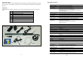
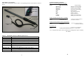
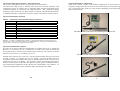
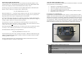
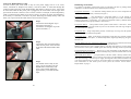
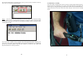
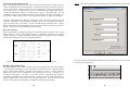
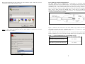
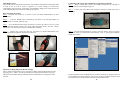
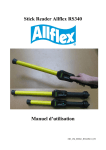
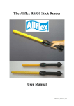
Allflex Australasia Sales Offices:
Allflex Australia
33 Neumann Rd
Capalaba, 4157
Brisbane , Australia
Tel 61 (07) 3245 9100
Fax 61 (07) 3245 9110
Allflex New Zeland
Private Bag 11003
Palmerston North
New Zealand
Tel 0011 646 356 7199
Fax 0015 646 355 3421
The Allflex RFID Stick Reader
Http://www.Allflex.com.au
ISO 11784 & 11785
This device complies with the standards set forward by the International Standardisation Organisation.
Specifically with standards
11784 : Radio frequency identification of animals -- Code Structure And
11785 : Radio frequency identification of animals -- Technical Concept.
FCC ID: NQY-930010
This device complies with Part 15 of the FCC Rules. Operation is subject to the following two conditions:
(1) this device may not cause harmful interference, and (2) this device must accept any interference received,
including interference that may cause undesired operation.
This device has been tested and meets the Electromagnetic Compatibility (EMC) requirements of EN50082-1
and EN50022 for the CE Declaration of Conformity (DoC).
Trademark Notices
HyperTerminal® is a registered trademark of Hilgraeve, Inc.
MS-Windows® is a registered trademark of Microsoft, Inc.
Configurator® is a registered trademark of Allflex USA, Inc.
User Manual
(Version 1.0 / 11- June -04 / Software V1.24+)
24
About This Guide
Information contained in this guide deals with operating the Allflex Stick Reader, using the
power supply, connecting the serial data ports and setting the Stick Readers configuration
options.
Unpacking
The Allflex Stick Reader is shipped to you in a box containing one each of the following
items.
1
Battery carry pouch.
2
PW-50 Ni-Cad battery pack.
3
5M Backup battery cable
4
Battery charger power lead.
5
60cm or 45cm Allflex Stick Reader.
6
1.8 m serial cable.
7
DC battery charger.
8
Belt clip
9
Allflex software disc.
SPECIFICATIONS:
GENERAL
RFID Compatibility:
Form Factor:
User Interface:
RS232 Serial Port:
Serial Data Format
Memory:
User Options:
Power/Data Interface:
Battery Power:
Agency Certifications:
(PENDING)
ISO 11784 & 11785 HDX and FDX-B
Portable Handheld Fiberglass Rod Enclosure w/Rubber Handle Grip
Single “Press to Read” Activation Button
Red LAMP “Exciter Active” Visual Indicator
Audible Beeper and Green LAMP “Good Read” Visual Indicator
RS232 Serial Data Port
Software upgradeable via RS232 serial port
1200 BPS to 57.6 KBPS (9600N81 default setting)
Decimal or Hexadecimal Mfr/Country Code + National ID Code
Stores up to 1,638 transponder codes in non-volatile memory for download
Non-volatile mode control options selectable via RS232 serial port interface
1 meter coilamp cable (extends to 3 meters) or 5 meter straight cable
w/DB9(f) connector & 2.5mm x 5.5mm coaxial power jack
6 to 12 VDC External Battery or Mains Powered Supply
Electromagnetic Compatibility - FCC Part 15 Class A, and CISPR 22
(EN55022), and EN50082-1
Product Safety - UL1950, IEC950 (CE Marked)
ISPRA Certification
PHYSICAL/ENVIRONMENTAL
1
2
2
3
4
5
Dimensions:
Weight:
Material:
Color:
Operate Temperature
Storage Temperature
Humidity:
Altitude:
Mechanical Shock:
Vibration:
Hermeticity:
8
60 cm or 45cm L x 32mm diameter (18” L x 1.25” diameter)
0.62 kg. (22 ounces)
UL94V0 Fiberglass and ABS UL94 HB Plastic
Black/Gray
-10ºC to +55ºC (IEC68.2.1/.2)
-40ºC to +85ºC (IEC68.2.1/.2)
0 to 95% (IEC68.2.56)
-100 to +3,000 meters
Per IEC 68-2-27 (15g/11mS sawtooth) & 1 meter free-fall drop onto
concrete)
Per IEC 68-2-6 (10-55 Hz sinusoidal/0.75mm displ./1 oct/min./10 cycles)
IP-67 (dust-tight/immersible) per IEC 529
RELIABILITY
9
MTBF:
MTTR:
Expected Life:
7
6
Figure 1 - Components shipped with Stick Reader
2
50,000 hours
0.5 hours (not field serviceable)
5 years, minimum
PERFORMANCE
Read Distance:
(@ 6 VDC)
(add 5 cm for 12VDC)
Reading Orientation:
Read Zone:
Interrogation Rate:
Read Error Rate:
Exciter Signal
Field Strength:
27cm (minimum - Allflex 30mm HDX/HP ear tag)
20cm (minimum – Allflex 31mm FDX-B ear tag)
0º to 45º with less than 10% range decrease
360º in radial and axial planes with respect to end of reader enclosure
~ 9 times/second
Less than 1 in 106
81 dBuV/m @ 10 meters with 6VDC power input
87 dBuV/m @ 10 meters with 12VDC power input
23
Your Allflex Installation CD
Special cautions and warnings
This equipment has been designed, constructed, and tested for compliance with FCC Rules that
regulate intentional and unintentional radiators. The user is not permitted to make any
modifications to this equipment or use it in any manner inconsistent with the methods described in
this User Manual, without express approval from Allflex. Doing so will void the user’s authority
to operate this equipment.
Allflex recommends that , as a precaution , persons with pacemakers should not uses this
device.
After inserting the cd into your CDROM, the cd will automatically start and
display the menu shown in figure 2 below. The menu items are listed with a simple
description in table 1 below.
Stick Reader Physical Integrity
The Stick Reader has been constructed from rugged and durable materials to provide long periods of
service in harsh environments. It is waterproof, and can withstand direct exposure to rain and small
amounts of water for cleaning purposes. The Stick Reader does contain electronic components,
however, that can be damaged if subjected to extreme intentional abuse, and such damage can
deteriorate or terminate the Reader’s functioning. The user should refrain from intentionally striking
other surfaces and objects with the Stick Reader. Damage resulting from such is not covered by the
Limited Product Warranty describe below.
Limited Product Warranty
Allflex warrants this product against any defects that are due to faulty material or workmanship for a
period of one year after date of purchase. This warranty does not apply to any damage to the product
resulting from accident, misuse, modification, or application other than that for which it is intended
and that is described within this User Manual.
If the product should become defective within the warranty period, Allflex will repair or replace it at
no charge. Allflex will return the product, shipping paid, provided it is shipped at customer cost to
Allflex. To obtain a return material authorization (RMA) code, please call Allflex at (07) 3245 9100,
or contact your Allflex sales representative.
Figure 2 - The Allflex CD menu screen.
Table 1 – Software menu screen layout.
Install NLIS Link 2.8 Installs the NLIS link program onto your PC.
Install Allflex Link
Installs the Allflex link program onto your PC.
2.8
Allflex Info
Displays general information about Allflex products.
Must have Adobe Acrobat Reader installed to view this
document.
NLIS Info
Displays detailed information on the
National
Livestock Identification Scheme. Must have Adobe
Acrobat Reader installed to view this document.
NLIS Video
General information video
Herd Test Video
General information video
VIC NLIS Video
NLIS information specifically for Victoria
Acrobat Reader 5.0
Installs Adobe Acrobat Reader 5.0. This software is
required to view the documents on this cd.
Exit
Exits the menu screen.
Installing programs from the cd
To install any program from the cd simply press the button corresponding with the program
that you wish to install. Read the instructions carefully and follow the steps provided.
22
3
Stick Reader User Interface
Each of the Stick Readers features and its corresponding function are described in Table 2
below.
Red Lamp
Antenna
Green Lamp
READ Button
DC Power
Jack
Audible Beeper
Soft Grip Handle
Data/Power
Cable
Command Language Examples:
Retrieve Current Configuration Settings:
User:
Reader:
P
Allflex Stick Reader
*HW V1.00
*SW V1.06
*PR V2.21
*B-840239
*S-4C
*I-01
*M-00
*A-3
*L-0000
*F-1638
Product Identity
Hardware Version Number
Software Version Number
Protocol Version Number
Serial Data Format Setting
RS232 Settings
Miscellaneous Settings
Memory Options
Read Time Interval
Memory ID Codes Stored
Memory ID Codes Vacant
Change Communications Bit Rate to 1200 BPS:
User:
S49<CR><LF>
Reader:
*S-49<CR><LF>
(<CR><LF> same as ‘Enter’)
Command Confirmed
Change ID Code Transmit Format to Hexadecimal:
User:
B850239<CR><LF>
Reader:
*B-850239
(<CR><LF> same as ‘Enter’)
Command Confirmed
Start Read Cycle:
User:
R
Reader:
(<CR><LF> not required)
LA_982_000000678234<CR><LF> (if tag found)
Strain Relief
Figure 3 – Features of The Allflex Stick Reader
For a complete description of all commands and configuration option variables, please
call Allflex
Table 2 - Stick Reader Features and Descriptions of Use
Feature
Description of Use
Antenna
Emits activation signal and receives transponder signal
Red Lamp
Illuminates whenever antenna is reading
Green Lamp
Illuminates whenever a transponder has been read
Audible Beeper
Beeps once on first transponder reading and twice for repeat
READ Button
Press this button to read a transponder
Data/Power Cable Conveys power to reader and serial data from reader
Serial Connector
Connects serial data to PC, scale head, data logger etc (using
RS232 communication)
DC Power Jack
Accepts 6 to 12 VDC input as reader power source
Soft Grip Handle
Rubber anti-slip gripping surface
Strain Relief
Watertight cable entry that resists cable breakage
4
21
Serial Command Language Method - Basic Instructions
This section is designed for the use of programmers and advanced users.
The instructions listed in table 5, describe some of the basic and more frequently used
configuration options. It illustrates how to implement them using the Stick Reader Serial
Command Language in conjunction with HyperTerminal®. The Command Language
method uses upper and lower case alpha characters combined with hexadecimal characters
to establish the Reader’s configuration. The most common commands are listed in Table 6.
Typical Stick Reader Configurations
Some of the common customer Stick Reader configurations are pictured below. While
using these configurations the user must be aware that the battery powering the weigh scale
may go flat quicker than normal. See “Special Notes Regarding Power Requirements” on
page 6 for more details.
Advanced Stick Reader Functions
Table 6 - Frequently Used Command Language Characters
Command
Application
P
Reader’s current settings are sent in command language format
Bnnnnnn
Configures ID code serial data format
Snn
Sets serial data communications parameters
Inn
Sets miscellaneous options
r
Resends the last tag read
G
Retrieves all ID codes stored in memory
M
Sets ID code memory options
C
Clears ID memory (requires <CR>
? or H
Retrieves list of valid Command Language characters
The Stick Reader connected to the Ruddweigh/Gallagher 600
Note 15 - In Table 6, commands followed with “n” (hexadecimal characters) require the user to
press the PC’s <Enter> key after typing in all command characters. Single letter commands do not
require <Enter> to be pressed, except as noted in Table 6.
Advanced Communication Options
ID Codes can be retrieved from the Stick Reader via its RS232 serial port by sending the
Reader a <G> command . The <G> command can be issued as many times as desired, and
the complete memory contents will be transferred upon each event. ID codes are not erased
from the memory until a <C> command is received.
The Stick Reader connected to the Trutest XR 3000
Each ID code is followed by a <CR><LF> (carriage return/line feed) which will cause each
ID code to appear on a separate line of a PC display. The Stick Reader contains a
configuration option that automatically inserts a null identification code in memory upon
application of power to the Reader. This provides a means of establishing partitions in
memory between blocks of ID codes that represent separate groups of identified animals,
thus facilitating the management of ID code data once downloaded to a PC database. To
set this partitioning marker, use the command <M02> (the default state is M00).
20
The Stick Reader in stand alone mode
5
Power Source Requirements
The Stick Reader is typically supplied with an Allflex PW-50 Battery as shown in figure 4
on page 7. It can be powered from a variety of DC power source options. These include a
car, truck, tractor, motorbike or dolphin torch battery using the stick readers backup battery
cable and the DC power jack located on the back of its serial connector or through the serial
connector itself using the PW-50 battery pack. For more details on using the backup battery
cable See page 8.
Special Notes Regarding Power Requirements
The stick reader can be powered by connecting it to some weigh scale heads instead of its
own stand alone battery source. In doing this, the user must be aware that the battery
powering the weigh scale may go flat quicker than normal.
The stick reader itself, does not contain an on/off switch. If the stick reader is left connected
to a battery that is switched on, it will consume small amounts of power until the battery is
flat . If connected to the Ni-Cad battery power source, ensure that the on/off switch on the
battery pack is turned off while not in use to conserve battery life.
The stick reader is also protected against accidental reverse voltage application and will not
be damaged if this occurs.
Configuration Options
The Stick Reader comes with a default configuration that will suit most scale heads without
modification. If however, it is necessary for these settings to be changed, it can be done in
one of two ways. The first being a set of code commands sent to the stick reader via its
RS232 serial communications, port or using a The Allflex Stick Reader Configurator
program. Once changed, the Stick Reader will retain these settings in memory until they are
intentionally changed by the user. For more information on changing these settings please
contact Allflex.
Table 5 lists the Stick Readers factory default configuration settings.
Table 5 - Default Configuration Options
Option
Default Configuration
Serial Data Format Per table 2, duplicate tag reads transmitted
Serial Hardware
9600 BPS, no parity, 8 BPW, 1 stop bit, no flow control
Miscellaneous
Beeper/LAMP = on, push-to-read, wireless sync = off
Read Time
3 seconds
Changing Configuration Options
Once communications have been established (see “Stick Reader Setup” on page 12 of this
guide), either of two methods can be used to change the Reader’s configuration. The first
method uses a terminal emulator program, such as HyperTerminal®, where the user must
type in short alphanumeric commands to make configuration changes. The second and
simplest method uses the Allflex Configurator® MS-Windows® based PC utility software
program, which allows the user to select configuration options from a series of drop-down
menu choices.
To make any changes to the stick readers configuration that are not covered in this manual
please contact Allflex Australia on (07) 3245 9100.
ID Code Memory
The Stick Reader contains an internal non-volatile memory capable of storing 1638 ID
codes. ID codes are stored automatically upon being read. A transponder ID code will not
be stored multiple times if read multiple times successively, but can be stored in memory
multiple times if other tags are read in between. All ID codes are retained when power to
the Stick Reader is shut off or set to the default factory settings. If more than 1638 ID
codes are read, the new ID codes are written over the oldest ID codes in a wrap-around
manner.
6
19
Interpreting Tag ID Code Information
Table 2 lists the default data formats that are transmitted from the Stick Reader’s serial
communications port. The default formats emulate the output of the TIRIS S2000 reader
that has been frequently used for animal identification in many venues.
For ISO type tags, there is no difference between HDX (Half Duplex) and FDX-B (Full
Duplex) outputs. Both types of tags produce a default format:
LA_982_000001088420<CR><LF>
Where the underscore “_” represents a space character, and <CR><LF> is a carriage return
/line feed (unprinted control characters which cause a PC’s display cursor to jump to the
beginning of the next line prior to displaying the next ID number).
In the above data output, the prefix “LA” represents “line mode – animal coded read only
tag”, “982” is the Allflex manufacturer number assigned by ICAR, and the last 12 digits is
a unique number sequence for this particular transponder.
The manufacturer code “982” will be different for another manufacturer’s tag, and can also be
replaced by an ISO country code (“250” = France, for example). When other manufacturer codes or
country codes exist, there can exist the same 12-digit ID number.
About The Allflex PW50 Battery Pack
The PW-50 is the standard battery shipped with all Allflex Stick Readers. The advantages
of using this battery are the following
•
•
•
•
•
The battery is rechargeable, and portable.
The battery supports continuous trickle charging.
There is an audible beeper built into the unit.
Convenient power and data connection via the battery’s RS232 serial port.
Rugged heavy duty construction.
Preparing For Use And Charging
To get the most out of the PW-50, the battery charge is cycled at the factory before
dispatch. This means that the battery pack is charged and discharged three times to heighten
the battery life expectancy. The battery is shipped in a discharged state meaning that prior
to the first use, the battery must be charged for a period of at least 16 hours. To get the most
out of the PW-50. Allflex recommends that the battery pack is completely discharged and
charged before any use. This can be done simply by placing a rubber band over the read
button. The battery will emit a series of beeps when it is almost fully discharged.
1
While HDX and FDX-B type transponders have an identical context, they are guaranteed by Allflex
to be unique. That is, HDX tag type ID numbers are never duplicated in FDX-B type tags.
5
For HDX Industrial coded tags, the output format is:
2
LR_0006_0000000018514348<CR><LF>
In this tag format, the prefix “LR” represents “line mode – industrial coded read only tag”,
“0006” is an application code unique to Allflex, and the last 16 digits comprise a unique
identifying number sequence.
3
4
The above default formats can be changed using the features described in the section
“Configuration Options” on page 19 of this guide.
Figure 4 - Features of The PW-50 Battery Pack
Table 3 – Battery Features And Description of Use
1 Battery pack on/off switch.
2 Plug the communications cable from your PC or scale head into this socket.
3 2.5mm DC power socket. Plug your DC battery charger into this socket to
charge the battery.
4 Red lamp displayed while battery is on charge.
5 Plug your stick reader into this socket for power and data transfer.
18
7
Using Your Backup Battery Cable
You can connect your stick reader to any 6V-12V power supply such as a car, truck,
tractor, motorbike or dolphin torch battery. The Stick reader is connected through the
socket located on the back of the Stick Readers data cable as shown in step 2. Users must
be aware that when the DC power jack is plugged in, the stick reader will no longer draw
power from the serial connector. This is a basic switch. For example, if the backup battery
cable is connected to the reader (as in step 2) it will try to derive its power from the battery.
If no battery is connected, it will have no power. Removing the backup battery cable will
allow you to power from the reader from its serial connector again.
Step 1
Connect the black alligator clip to
the negative terminal (-).
Connect the red alligator clip to the
positive terminal (+).
Read Range Performance
Tag readers are frequently assessed with respect to performance by their tag reading distance. The
read distance of the Stick Reader will be affected by the following:
Transponder Orientation - For maximum reading distance, the axes of the transponder and reader
antenna coils must be optimally oriented (see Figure 7).
Transponder Quality - Each manufacturer’s transponder differs in (a) the amount of energy
necessary to for the tag to generate a signal , and (b) the signal level of the information that is
returned to the reader. Consequently, it is normal for transponders made by different manufacturers
to exhibit different read range performance characteristics.
Transponder Motion - Most portable readers produce small effective “read zones”. Transponders
that are moving quickly past the reader may not be in the antennas read zone long enough for all the
tag information to be obtained.
Transponder Size - Larger transponders generally contain larger receiving coils that produce longer
reading distances than smaller transponders.
Transponder Type - HDX, or half duplex transponders (NLIS cattle tag) generally exhibit greater
reading distances than full duplex , or FDX-B transponders (Lightweight sheep tag) of approximately
the same size.
Step 2
Connect the other end of the battery
cable into the power socket located
at the end of the Stick Readers data
cable
Proximal Metallic Objects And Electrical Interference - Metal objects located near the transponder or
Reader can diminish the read distance and performance of both devices.
Radiated electrical noise from computer displays, and other such appliances can also interfere with
the transmission and reception of RFID signals, thus reducing read range and device performance.
Transponder/Reader Interference - Having two or more transponders in the immediate vicinity can
dramatically affect the reading performance and temporarily prevent the Stick Reader from reading.
Step 3
You should now be ready to start
using your stick reader. Press the
READ button momentarily and
observe the red lamp flashes for
approximately 3 seconds and then
stops.
8
Stick Reader Power Source - The performance of the stick reader is directly related to the amount
of power that the stick reader receives from its power source. The Stick Reader will operate at its best
when powered using a stand-alone power supply. Rechargeable sealed lead acid batteries rated to 12
volts and 4.5 ampere-hours or greater are an excellent choice for portable and field applications. For
more information on stick reader power sources please the read the section “Power Source
Requirements” on page 6.
17
If you wish to disconnect or re-connect at any time you can use the two buttons in the top
left corner of your HyperTerminal Window.
Portable Battery Assembly
The stick reader is supplied with a few accessories to make portable field operations easy.
The first of the two is the battery carry pouch. This holds the battery pack tightly and
simply clips on using the belt clip provided. The second is the stick reader belt clip. This
simply slides down to the base of the stick reader and clips to the users belt. See figure 5
below.
Step 6 - Next, be sure that your Stick Reader is turned on and press the read button. Bring
a tag to within 15 cm (6”) of the antenna ,see figure 7 on page 11. Observe the green light
briefly flash, indicating a successful read. The HyperTerminal® window, should now have
a transponder id code.
Even if the user’s intends to use a program other than HyperTerminal® completing the
steps above ensure that (a) the Stick Readers operation and communication is verified ,and
(b) the user becomes familiar with the basic operation of both the stick reader and
HyperTerminal® as a backup precaution.
16
Figure 5 – The portable battery pack assembly
9
Serial Data Interface Requirements
Data is transmitted between the stick reader and the scale head and/or computer using a
system called RS232 serial communications. The RS232 serial data connection consists of
a 3 wire arrangement .Transmit (TxD/pin 2), receive (RxD/pin 3), and ground (GND/pin 5).
This interface can be configured for a variety of communications settings, and is factory
configured with default settings of 9600 baud, no parity, 8 data bits, and 1 stop bit
(“9600N81”). This is the standard setting for communicating with most scale heads. To
change these default settings, please see “Configuration Options” on page 20 of this guide.
Step 5 - Now set the properties for the connection to the following. Then press OK.
The stick readers RS232 port interface is designed to connect directly to the serial port of a
computer, scale head or any other RS232 compliant device. If you find that the length of
your serial data cable is too short, it can be extended using a standard male to female
RS232 cable which can be purchased from most computer shops. Extensions longer than 2
meters (~6 feet) are not recommended for data and power.
How Does It Work?
When a transponder is scanned, data appears on the Stick Reader’s transmit pin (pin 2) in a
format known as ASCII. The ASCII language is compatible with most PC terminal
emulator programs, e.g. HyperTerminal®. The returned data is then filtered into a readable
format and is displayed or sent to the connected appliance.
Step 5 - Setting up your connection properties
Figure 6 - Stick Reader Power Jack and Data Connector Wiring Diagram
Notice the caption and time label down the bottom left hand corner of the screen showing
the status of the connection.
Reading Transponder Tags
The Stick Reader is always ready to read an electronic tag when power has been applied to
it. Pressing the read button on your stick reader will start this process. When the READ
button is pressed and released, it searches for an electronic tag for a 3 second period by
default. This option can be configured to intervals between 1 second, 9 seconds or to a
continuous read signal , see page 11 for issues with the continuous read function.
Alternately, the READ button can be held down, and the activation signal will remain on
until the READ button is released or until a tag has been read. You can tell if the stick
reader is searching for a transponder by looking for the flashing red read light .
10
15
When HyperTerminal® has fully loaded you will be asked to input a name for your new
connection. We’ll call this connection “Test”.
Issues With The Continuous Read Function
The Stick Reader can be configured for a continuously on activation signal, thus
eliminating the need to press the READ button. In continuous mode, the stick reader will
constantly search for an electronic tag When a tag is found it will continue to search
immediately after. This mode should be used only when (a) powering the Stick Reader
from a 6 volt power source, (b) when interference with other electronic tag readers is not
likely, and (c) when powering the Reader from a source that can provide sufficient
operating time (see page 6 for power source options). For information about enabling
continuous read mode please call Allflex
Figure 7 - The Stick Reader read zone
Step 3 - Starting a new connection
Step 4 - Next, select the COM Port that your Stick Reader is connected to. On most
computers this will be COM 1.
Figure 7 illustrates the read zone of the Stick Reader, Tags within this field can be
successfully detected and read. Optimum read distance is achieved by aligning the
transponder with the stick readers antenna as shown.
Table 3 lists the typical read distances that can be expected when operating the Stick
Reader at different power levels and when reading different types of Allflex ear tags,.
Table 4 - Typical read distances for various Allflex ear tags
Allflex PW-50 Battery Pack
Tag Type
HDX/HP Ear tag (NLIS cattle tag)
25 – 30 cm
FDX-B Ear tag (small stock/sheep tag)
15 – 20 cm
Step 4 – Selecting the right connection
14
11
Stick Reader Setup
The Stick Reader is configured at the factory with standard configuration settings that make
it ready to use as soon as power is supplied to it. These settings are selected for
compatibility with most users’ applications, and should be changed only when the user has
a full understanding of the effects of changing each option.
Connecting And Testing The Stick Reader Using HyperTerminal®
Step 1 - Step 1 assumes that you have successfully completed steps 1 through to 4 in the
basic operations walk through on page 12.
Step 2 - Connect the serial cable to the computers COM port (COM1 is the most common
port used).
Basic Operating Procedure
Step 1 - Turn the stick reader on, or connect to your scale head, standard battery or other
power source
Step 2 - Press the READ button momentarily, and observe the red light flashes for
approximately 3 seconds, and then stops.
Step 3 - Press the READ button again, and bring a electonic tag within 15 cm (6”) of the
end of the Stick Reader. Observe the green light illuminates briefly with the beeper,
indicating a successful read, and the red LAMP ceases flashing.
Step 4 - Repeat step 3 using the same tag, and observe a double flash/double beep,
indicating that the transponder tag has been read twice.
Step 1 - Connecting the power cables
Step 2 - Observe red LAMP
Step 3 - Read transponder
Step 4 – 2 beeps while green LAMP flashes
Special Notes Regarding Stick Reader Settings
Factory default configuration can be restored by holding down the READ button while
applying power. After 2 seconds, the Reader will respond with 6 flashes of its green
indicator (and 6 audible beeps) indicating that the standard factory settings have been
restored.
12
Step 2 – Connecting to comm. port 1
Step 3 - Launch HyperTerminal® by going to the Start button, then to Programs then to
accessories then to Communications and finally click on the HyperTerminal® icon to
launch the program.
Step 3 - Selecting The HyperTerminal® Program
HyperTerminal® comes standard with any windows installation, though versions may vary
across different operating platforms. The version of HyperTerminal® used for the photos in
this manual is the version installed with Microsoft Windows 2000.
13