1
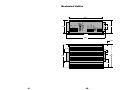
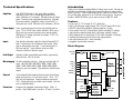
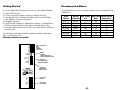
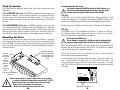
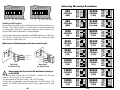
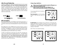
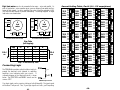
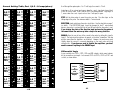
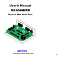
4/18/96
User's Manual
PD5580
Step Motor Driver
DIR+
DIR–
STEP+
STEP–
EN+
EN–
FAULT+
FAULT–
POWER
OVER TEMP
OVER CURRENT
1 2 3 4
MICROSTEP
RESOLUTION
1 2 3 4 5 6 7
50% IDLE
0.1
0.2
0.4
0.8
1.6
1.9
CURRENT
(BASE = 0.5 A)
AC POWER
MOTOR
PD5580
Step Motor Driver
B–
B+
A–
A+
GND
N
L
NEAR
R
E
W
PO
404 Westridge Drive Watsonville, CA 95076
Tel (408) 761-6555
(800) 525-1609
Fax (408) 761-6544
LY
LI
Applied Motion Products, Inc.
SUPP
motors • drives • controls
Mechanical Outline
8.00 "
DIR+
DIR–
STEP+
STEP–
EN+
EN–
FAULT+
FAULT–
POWER
OVER TEMP
OVER CURRENT
50% IDLE
0.1
0.2
0.4
0.8
1.6
1.9
5.45 "
1 2 3 4 5 6 7
5.30 "
CURRENT
(BASE = 0.5 A)
MICROSTEP
RESOLUTION
1 2 3 4
PD5580
Step Motor Driver
B–
B+
A–
A+
GND
L
N
-19-2-
0.25"
2.15"
1.25 " 3.00 "
MOTOR
AC POWER
3.07 "
8.97 "
9.25 "
0.06"
2.02 "
Technical Specifications
Amplifiers
Dual, MOSFET H-bridge, 3 state, pulse width modulated
switching at 20 kHz. 0.5 - 5.5 amps/phase output current,
switch selectable in 0.1 increments. 400 watts maximum output
power. Overcurrent and overtemperature protection. Automatic
idle current reduction (defeatable), reduces current to 50% of
setting after one second. Minimum motor inductance is 0.8 mH.
Power Supply
Linear, toroidal transformer based for high reliability and low
noise. 110 or 220 VAC input, switch selectable. 60 Hz only (a
50 Hz version for overseas operation can be special ordered).
400 W max. DC voltage at nominal line voltage: 75 VDC full
load, 90 VDC no load.
Inputs
Step, direction and enable, optically isolated, differential 5-12V
logic. 5 mA mininum, 20 mA maximum input current. Motor
steps on falling edge of step input. 1 µsec minimum pulse, 2
MHz max step rate. 1 µsec minimum set up time, 50µs
minimum hold time for direction signal.
Optically isolated, uncommitted (open collector, open emitter)
photo transistor. 30V, 20 mA max.
Physical
Block Diagram
110/220
VAC
step+
step–
dir+
dir–
enable+
enable–
Power
Amplifier
2 3 4 5 6 7
Isolation
Fault
Monitor
overcurrent
overtemp
-3-
1
-18-
+80V
Microstep
Sequencer
fault
lights
fault+
fault–
Power
Supply
Optical
Isolation
microstep
resolution
European style, pluggable screw terminal blocks. Motor: 4
position. Signal Input/output: 8 position. AC Input: 3 position.
power light
fuse
1 2 3 4
Connectors
Constructed with black anodized aluminum heat sink and heavy
gauge steel housing. 3 x 5.3 x 8 inches overall. 7.8 lbs. 70 C
max. heat sink temperature. Power,overtemp and overcurrent
LEDs. Mounting brackets and switch cover included. See back
cover for detailed drawing .
Features
• Drives sizes 14 (1.4") through 42 (4.2") step motors
• Built in 80 volt power supply (accepts 110 or 220 VAC power, 60 Hz only)
• MOSFET pulse width modulation switching amplifiers (3 state)
• Phase current from 0.5 to 5.5 amps/phase (switch selectable, 51 settings)
• Step, direction, amplifier enable inputs, fault output, optically isolated
• Microstepping from full step through 1/ 254 (switch selectable, 16 settings)
• Overtemp and overcurrent (short circuit) and surge protection
• Idle current reduction (50%, switch selectable)
• pluggable screw terminal connectors
motor
current
50% idle
on/off
motor phase B
Microstepping 16 switch selectable resolutions. Steps per revolution with 1.8
motor: 200, 400, 1000, 2000, 5000, 10000, 12800, 18000,
20000, 21600, 25000, 25400, 25600, 36000, 50000, 50800.
Waveform: pure sine standard. Other waveforms available upon
request.
Thank you for selecting an Applied Motion Products motor control. We hope our
dedication to performance, quality and economy will make your motion control
project successful. If there's anything we can do to improve our products or help
you use them better, please call or fax. We'd like to hear from you. Our phone
number is (800) 525-1609 or you can reach us by fax at (408) 761–6544.
motor phase A
Fault Output
Introduction
Getting Started
Recommended Motors
To use your Applied Motion Products motor control, you will need the following:
The following tables lists motors and current settings that are recommended for the
PD5580 drive.
✔ a power cable (line cord)
✔ a source of step pulses capable of sourcing or sinking at least 5 mA
✔ if your application calls for bidirectional rotation, you'll also need a direction
signal, capable of sourcing or sinking 5 mA
✔ a compatible step motor
✔ a small flat blade screwdriver for tightening the connectors - an Applied Motion
Products screwdriver suitable for this purpose is included with your drive.
✔ if you want to power the drive from 220 volts, you'll need a Philips screwdriver to
remove the cover
The sketch below shows where to find the important connection and adjustment
points. Please examine it now.
All mating connectors are included.
DIR+
DIR–
STEP+
STEP–
EN+
EN–
FAULT+
FAULT–
DIR
STEP
ENABLE
FAULT OUT
POWER
LEDs
OVER CURRENT
switches
1 2 3 4
MICROSTEP
RESOLUTION
POWER
OVER TEMP FAULT
OVER CURRENT FAULT
1 2 3 4 5 6 7
50% IDLE
0.1
0.2
0.4
0.8
1.6
1.9
Winding Max Torque
Connection
oz-in
parallel
75
parallel
120
parallel
177
parallel
185
parallel
300
parallel
390
parallel
595
logic connector
OVER TEMP
CURRENT
(BASE = 0.5 A)
Motor
Number
5023-122
5023-123
5023-124
5034-348
5034-349
5034-350
5042-022
IDLE REDUCTION
PHASE CURRENT
switches
AC POWER
MOTOR
MICROSTEP
RESOLUTION
B–
B+
A–
A+
connector
GND
connector
N
AC POWER
MOTOR
L
-4-
-17-
Max Power Current Setting
Watts
Amps/phase
60
2.0
93
2.5
110
3.5
133
4.8
151
5.0
213
5.5
300
5.5
Fault Protection
Connecting the AC Line
The PD5580 provides protection against motor short circuits and excessive drive
temperature.
If the OVERTEMP light is on the PD5580 has detected a thermal problem and
shut down the amplifiers. The first thing you should do is to unplug the drive from
the power source. Next, touch the heat sink with your fingers. If it is very hot, the
drive has probably overheated. Usually this means you need more air flow around
the drive.
If the OVERCURRENT light is on the PD5580 has detected a short circuit and
has shut down the amplifiers. Unplug the drive from the power source. Check the
motor wiring carefully. Make sure that the connections to the drive are secure and
that any unused motor leads are insulated from the drive and power supply and
from each other. Check the motor leads for shorts between phases or to ground.
!
110 Volts
The PD5580 is set for 110 volt operation at the factory. All you need to do is install
a power cord and plug it in. If you want to direct wire the PD5580 to AC power, you
must consult a qualified electrician and observe all building and electrical codes.
The AC cord you can install yourself, but be careful: AC power can be dangerous.
220 Volts
The PD5580 is set for 110 volt operation at the factory. In order to use 220 volts,
you'll need to change a switch setting inside the case. However, you can do this
from the outside with your Applied Motion screwdriver.
Mounting the Drive
You can mount your drive on the wide or the narrow side of the case. Either way
you'll need to get the brackets and screws out of the accessory bag and bolt them
onto the PD5580. If you're mounting on the narrow side, you'll first have to remove
one of the screws from the heat sink, then put it back with the bracket in place, as
shown in the figure.
Bracket position for
wide side mounting.
Place brackets on
top and bottom of
drive.
Before you can change the 100/220 volt switch setting, you must remove the motor
connector and the AC power connector from the drive. Set the drive on the widest
side, so that the heat sink fins are pointing upward.
Once you've done that, you'll see an opening in the case, just above the three
position and four position green connectors.
If you look into the slot, you should see two black objects. The one on the left is the
fuse. The black object to the right of the fuse is the 110/220 volt switch. The
sketches below and on page 6 show the two positions of the switch. To change
from 110V to 220V, carefully insert your scredriver into the slot and push the switch
to the right.
AC POWER
MOTOR
B–
B+
A–
A+
L
N
!
Never use your drive in a space where there is no air flow
or where the ambient temperature exceeds 50°C (120°F).
Never block the fins of the heat sink or the vent holes.
Never put the drive where it can get wet.
Never allow metal particles near the drive.
-16-
GND
This screw is already in
the drive.
!
Do not open the PD5580 case.
Do not attempt to change the 110/220 volt switch setting until the
power has been removed from the drive for at least five minutes.
Unplug these connectors
-5-
PD5580
Step Motor Driver
Bracket
position
for narrow
side
mounting.
Place
brackets
on top
and
bottom of
drive.
If you plan to operate the PD5580 outside of North America, in a
country where the powerline frequency may be less than 60 Hz,
you must order the special 50 Hz version of the PD5580.
B–
B+
A–
A+
GND
N
L
B–
B+
A–
A+
N
L
GND
Selecting Microstep Resolution
1 2 3 4
1 2 3 4
1 2 3 4
1 2 3 4
1 2 3 4
1 2 3 4
-15-
1 2 3 4
STEPS/REV
(1/254)
1 2 3 4
50800
MICROSTEP
RESOLUTION
STEPS/REV
(.02°)
STEPS/REV
(1/250)
MICROSTEP
RESOLUTION
18000
STEPS/REV
(.01°)
MICROSTEP
RESOLUTION
STEPS/REV
(1/64)
50000
STEPS/REV
(1/128)
MICROSTEP
RESOLUTION
-6-
12800
STEPS/REV
(1/127)
MICROSTEP
RESOLUTION
Always unplug the line cord from the wall before attaching it
!
to the PD5580
•Connect the black or brown wire to the PD5580 "L" terminal of the AC power
connector. That is the line, or "hot" connection.
•Connect the white or blue wire to neutral. That's the "N" terminal.
•Finally, and most importantly, connect the green wire to the GND terminal. That
connects the PD5580 metal enclosure and DC power supply ground to earth
ground.
STEPS/REV
(1/50)
36000
STEPS/REV
(1/125)
MICROSTEP
RESOLUTION
"New Style"
AC Power Plug
10000
STEPS/REV
(1 arc min)
MICROSTEP
RESOLUTION
black
STEPS/REV
(1/100)
MICROSTEP
RESOLUTION
"Old Style"
AC Power Plug
To Neutral
To Line (Hot)
1 2 3 4
To Line (Hot)
1 2 3 4
n
green
white
To Earth Ground
25600
1 2 3 4
To Neutral
25400
1 2 3 4
To Earth Ground
1 2 3 4
o
whit e r blue
o
black r brow
1 2 3 4
STEPS/REV
(1/25)
green
1 2 3 4
5000
1 2 3 4
2000
STEPS/REV
(1/10)
25000
MICROSTEP
RESOLUTION
Make sure you follow the proper sketch your connector style.
1000
STEPS/REV
(1/5)
MICROSTEP
RESOLUTION
The AC power plug that was shipped with your PD5580 might be one of two types.
The "old style" is shown below, on the left. The "new style" (shown on the right)
comes with an insulating rubber boot.
STEPS/REV
(HALF)
21600
MICROSTEP
RESOLUTION
Installing an AC Line Cord
Remove about 5 mm (3/16 inches) of insulation from each of the three wires of your
line cord. (That's right, three wires. For safety, always use a three wire power cord
on anything with a metal case.) Depending on where you got your power cord, it
may have black, white and green wires or brown/blue/green.
400
MICROSTEP
RESOLUTION
switch in 220V position
MICROSTEP
RESOLUTION
fuse
switch in 110V position
MICROSTEP
RESOLUTION
fuse
20000
MICROSTEP
RESOLUTION
STEPS/REV
(FULL)
MICROSTEP
RESOLUTION
200
Idle Current Reduction
Your drive is equipped with a feature that automatically reduces the motor current
by 50% anytime the motor is not moving. This reduces drive heating by about 50%
and lowers motor heating by 75%. This feature can be disabled if desired so that
full current is maintained at all times. This is useful when a high holding torque is
required. To minimize motor and drive heating we highly recommend that you use
the idle current reduction feature unless your application strictly forbids it. Idle
current reduction is enabled by sliding switch #1 toward the 50% IDLE label,as
shown in the sketch below. Sliding the switch away from the 50% IDLE label
disables the reduction feature.
1
1
Idle Current Reduction
Selected
Connecting the Motor
!
Never connect the motor to the driver when the AC power is on.
Secure any unused motor leads.
Never disconnect the motor while the AC power is on.
Never connect motor leads to ground or to a power supply.
You must now decide how to connect your
motor to the drive.
A+
Four lead motors can only be connected
one way. Please follow the sketch at the
right.
Red
4
lead
motor
A–
Blue
Yellow
B+
No Current Reduction
White
B–
4 Leads
Microstepping
Most step motor drives offer a choice between full step and half step resolutions. In
full step mode, both motor phases are used all the time. Half stepping divides each
step into two smaller steps by alternating between both phases on and one phase
on.
Microstepping drives like the PD5580 precisely control the amount of current in
each phase at each step position as a means of electronically subdividing the steps
even further. The PD5580 offers a choice of full and half step as well as 14 other
step resolutions. The highest setting divides each full step into 254 microsteps,
providing 50,800 steps per revolution when using a 1.8° motor.
Six lead motors can be connected in series or center tap. In series mode, motors
produce more torque at low speeds, but cannot run as fast as in the center tap
configuration. In series operation, the motor should be operated at 30% less than
the rated current to prevent overheating. Winding diagrams for both connection
methods are shown below.
Note: NC means not connected to anything.
A–
In addition to providing precise positioning and smooth motion, microstep drives
can be used for motion conversion between different units. The 25,400 step/rev
setting is provided as a means of converting motion from metric to english. (There
are 25.4 mm in an inch.) Other settings provide step angles that are decimal
degrees (36,000 steps/rev makes the motor take 0.01° steps.) Some settings are
used with lead screws. When the drive is set to 2000 steps/rev and used with a 5
pitch lead screw, you get .0001 inches/step.
NC
A+
Grn/Wht
A– Grn/Wht
6
lead
motor
White
Green
A+
NC
Red
B–
Red/
Wht
Black
NC
Green
Red
B–
B+
6 Leads Series Connected
-14-
6
lead
motor
White
Red/
Wht
Black
B+
NC
6 Leads Center Tap Connected
-7-
The PD5580 drive contains optical isolation circuitry to
prevent the electrical noise inherent in switching
amplifiers from interfering with your circuits. A
schematic diagram of the step input circuit is shown
below. The DIRECTION and ENABLE circuits are the
same as STEP.
680
0.1
3.8 0.2
0.4
AMPS/ 0.8
PHASE 1.6
1.9
0.1
4.4 0.2
0.4
AMPS/ 0.8
PHASE 1.6
1.9
0.1
4.9 0.2
0.4
AMPS/ 0.8
PHASE 1.6
1.9
0.1
5.0 0.2
0.4
AMPS/ 0.8
PHASE 1.6
1.9
PD5580 Input Circuit
Your logic signals can be sourcing, sinking or both (differential). The input current
will be about 1 mA per volt. Thus, if your logic signals are 5 volts, you'll be putting
-8-
-13-
2 3 4 5 6 7
Connecting Logic
0.1
4.3 0.2
0.4
AMPS/ 0.8
PHASE 1.6
1.9
2 3 4 5 6 7
Step 2 is the Power Up State
0.1
3.7 0.2
0.4
AMPS/ 0.8
PHASE 1.6
1.9
2 3 4 5 6 7
DIR=0
ccw
2 3 4 5 6 7
B–
+
+
–
–
2 3 4 5 6 7
B+
+
–
–
+
+
0.1
5.4 0.2
0.4
AMPS/ 0.8
PHASE 1.6
1.9
0.1
5.5 0.2
0.4
AMPS/ 0.8
PHASE 1.6
1.9
2 3 4 5 6 7
A–
–
+
+
–
0.1
4.8 0.2
0.4
AMPS/ 0.8
PHASE 1.6
1.9
2 3 4 5 6 7
A+
+
+
–
–
+
0.1
4.2 0.2
0.4
AMPS/ 0.8
PHASE 1.6
1.9
0.1
5.3 0.2
0.4
AMPS/ 0.8
PHASE 1.6
1.9
2 3 4 5 6 7
DIR=1
cw
Step
0
1
2
3
4
0.1
3.6 0.2
0.4
AMPS/ 0.8
PHASE 1.6
1.9
0.1
5.2 0.2
0.4
AMPS/ 0.8
PHASE 1.6
1.9
2 3 4 5 6 7
Step Table
(full stepping)
0.1
5.1 0.2
0.4
AMPS/ 0.8
PHASE 1.6
1.9
2 3 4 5 6 7
8 Leads Parallel Connected
2 3 4 5 6 7
8 Leads Series Connected
Red/Wht B–
0.1
4.7 0.2
0.4
AMPS/ 0.8
PHASE 1.6
1.9
2 3 4 5 6 7
Yel/
B+ Wht
0.1
4.1 0.2
0.4
AMPS/ 0.8
PHASE 1.6
1.9
2 3 4 5 6 7
Yel/
Wht B–
0.1
3.5 0.2
0.4
AMPS/ 0.8
PHASE 1.6
1.9
2 3 4 5 6 7
Yellow
0.1
4.6 0.2
0.4
AMPS/ 0.8
PHASE 1.6
1.9
2 3 4 5 6 7
B+
Red/
Wht
Yel
low
0.1
4.5 0.2
0.4
AMPS/ 0.8
PHASE 1.6
1.9
2 3 4 5 6 7
Red
Black
Red
2 3 4 5 6 7
Black
0.1
4.0 0.2
0.4
AMPS/ 0.8
PHASE 1.6
1.9
2 3 4 5 6 7
Org/
Wht
A–
0.1
3.4 0.2
0.4
AMPS/ 0.8
PHASE 1.6
1.9
8
lead
motor
2 3 4 5 6 7
Blk/Wht
A–
Blk/Wht
8
lead
motor
Org/Wht
Orange
2 3 4 5 6 7
A+
0.1
3.9 0.2
0.4
AMPS/ 0.8
PHASE 1.6
1.9
2 3 4 5 6 7
Orange
0.1
3.3 0.2
0.4
AMPS/ 0.8
PHASE 1.6
1.9
2 3 4 5 6 7
A+
Current Setting Table, Part 2 (3.3 - 5.5 amps/phase)
2 3 4 5 6 7
Eight lead motors can also be connected in two ways: series and parallel. As
with six lead motors, series operation gives you more torque at low speeds and less
torque at high speeds. In series operation, the motor should be operated at 30%
less than the rated current to prevent overheating. The wiring diagrams for eight
lead motors are shown below.
5 mA through the optocouplers. For 12 volt logic, the current is 12 mA.
Current Setting Table, Part 1 (0.5 - 3.2 amps/phase)
2 3 4 5 6 7
2 3 4 5 6 7
2 3 4 5 6 7
0.1
3.2 0.2
0.4
AMPS/ 0.8
PHASE 1.6
1.9
2 3 4 5 6 7
2 3 4 5 6 7
2 3 4 5 6 7
2 3 4 5 6 7
-12-
0.1
3.1 0.2
0.4
AMPS/ 0.8
PHASE 1.6
1.9
2 3 4 5 6 7
2 3 4 5 6 7
0.1
2.5 0.2
0.4
AMPS/ 0.8
PHASE 1.6
1.9
0.1
3.0 0.2
0.4
AMPS/ 0.8
PHASE 1.6
1.9
2 3 4 5 6 7
2 3 4 5 6 7
0.1
2.4 0.2
0.4
AMPS/ 0.8
PHASE 1.6
1.9
0.1
2.9 0.2
0.4
AMPS/ 0.8
PHASE 1.6
1.9
2 3 4 5 6 7
2 3 4 5 6 7
0.1
2.3 0.2
0.4
AMPS/ 0.8
PHASE 1.6
1.9
0.1
2.8 0.2
0.4
AMPS/ 0.8
PHASE 1.6
1.9
2 3 4 5 6 7
2 3 4 5 6 7
0.1
2.2 0.2
0.4
AMPS/ 0.8
PHASE 1.6
1.9
0.1
2.7 0.2
0.4
AMPS/ 0.8
PHASE 1.6
1.9
2 3 4 5 6 7
2 3 4 5 6 7
0.1
2.1 0.2
0.4
AMPS/ 0.8
PHASE 1.6
1.9
0.1
2.6 0.2
0.4
AMPS/ 0.8
PHASE 1.6
1.9
2 3 4 5 6 7
0.1
2.0 0.2
0.4
AMPS/ 0.8
PHASE 1.6
1.9
2 3 4 5 6 7
0.1
1.9 0.2
0.4
AMPS/ 0.8
PHASE 1.6
1.9
2 3 4 5 6 7
0.1
1.8 0.2
0.4
AMPS/ 0.8
PHASE 1.6
1.9
2 3 4 5 6 7
0.1
1.7 0.2
0.4
AMPS/ 0.8
PHASE 1.6
1.9
2 3 4 5 6 7
0.1
1.1 0.2
0.4
AMPS/ 0.8
PHASE 1.6
1.9
0.1
1.6 0.2
0.4
AMPS/ 0.8
PHASE 1.6
1.9
2 3 4 5 6 7
0.1
1.0 0.2
0.4
AMPS/ 0.8
PHASE 1.6
1.9
0.1
1.5 0.2
0.4
AMPS/ 0.8
PHASE 1.6
1.9
2 3 4 5 6 7
0.1
0.9 0.2
0.4
AMPS/ 0.8
PHASE 1.6
1.9
0.1
1.4 0.2
0.4
AMPS/ 0.8
PHASE 1.6
1.9
2 3 4 5 6 7
0.1
0.8 0.2
0.4
AMPS/ 0.8
PHASE 1.6
1.9
0.1
1.3 0.2
0.4
AMPS/ 0.8
PHASE 1.6
1.9
2 3 4 5 6 7
0.1
0.7 0.2
0.4
AMPS/ 0.8
PHASE 1.6
1.9
0.1
1.2 0.2
0.4
AMPS/ 0.8
PHASE 1.6
1.9
2 3 4 5 6 7
0.1
0.6 0.2
0.4
AMPS/ 0.8
PHASE 1.6
1.9
2 3 4 5 6 7
0.1
0.5 0.2
0.4
AMPS/ 0.8
PHASE 1.6
1.9
Logic low, or 0, for a given input occurs when the + and – signal pins have at least
4 volts DC across them. In this state the LED is conducting current. Logic high, or
1, occurs when the + and – inputs are less than 1 volt apart, or open.
STEP tells the driver when to move the motor one step. The drive steps on the
falling edge of the pulse. The minimum width is 1 microsecond.
DIRECTION signals which way the motor should turn. See the step table on page 7
for details. The DIRECTION signal should be changed at least 1 microsecond
before a step pulse is sent and held for at least 50 µsec after the step pulse is sent.
If you change the state of the direction input and send a step pulse at
the same instant the motor may take a step in the wrong direction.
ENABLE allows the user to turn off the current to the motor by setting this signal to
logic 0. The logic circuitry continues to operate, so the drive "remembers" the step
position even when the amplifiers are disabled. However, the motor may move
slightly when the current is removed depending on the exact motor and load
characteristics. If you have no need to disable the amplifiers, you don't
need to connect anything to the ENABLE input.
Differential Logic
If your controller has STEP+, STEP-, DIR+ and DIR- outputs, which many indexers
do, the connections are simple. Just connect STEP+ to STEP+, STEP- to STEP- and
so forth, as shown below.
Indexer
or
Controller
with
Differential
Outputs
DIR+
DIR+
DIR-
DIR-
STEP+
STEP+
STEP-
STEP-
ENABLE+
ENABLE+
ENABLE-
ENABLE-
= optional signal
-9-
PD5580
Drive
Sinking Logic
If your controller has STEP, DIR and +5V outputs, like the Applied Motion Products
SI-1 indexer, connect STEP+ and DIR+ to +5V. Connect STEP- to STEP. Connect
DIR- to DIR.
Indexer
or
Controller
with
Sinking
Outputs
+5V OUT
DIR+
DIR
DIRSTEP+
STEP
STEP-
PD5580
Drive
The PD5580 has a fault output to tell you if the drive has overheated or if a short
circuit has occured at the motor outputs. The fault output is optically isolated for
noise immunity. This makes it more flexible and more reliable, but also harder to
hook up. To connect to 5 volt logic, follow the sketch below. For other
connections, consult the factory.
The photo transistor turns on when there is a fault. In circuit below, the signal will
be high (near 5 volts) when there is no fault. The signal will go low (0 volts) if a
fault occurs.
PD5580
ENABLE+
ENABLE-
ENABLE-
TTL or CMOS input
Sourcing Logic
If your controller has STEP, DIR and GND (ground or common) outputs, connect
STEP- and DIR- to GND. Connect STEP+ to STEP. Connect DIR+ to DIR.
DIR
DIRSTEP+
STEPENABLE
ENABLE+
GROUND
ENABLE-
PD5580
Drive
= optional signal
The PD5580 optical isolation circuits have built in resistors for 5 - 12 volt logic. If
your logic voltage is greater than 12 volts but no more than 24 volts, you can add
series resistors to the signal "+" pins (i.e. STEP+, DIR+, etc). Use 1/4 watt, 1000
ohms.
Current Setting Formula
Locate the bank of eight switches. Six of the switches have a value of current
printed next to them, such as 0.1 and 1.6. Each switch controls the amount of
current, in amperes (A), that it's label indicates. There is always a base current of
0.5 A. To add to that, slide the appropriate switches toward their labels. You may
need your small screwdriver for this.
Example
Suppose you want to set the driver for 4 amps
per phase. You need the 0.5 A base
CURRENT
current plus another 1.6 and 1.9 A.
(BASE=0.5A)
4.0 (TOTAL) = 0.5 (BASE) + 1.6 + 1.9
Slide the 1.6 and 1.9 A switches toward the labels
as shown in the figure.
-11-
0.1
0.2
0.4
0.8
1.6
1.9
2 3 4 5 6 7
If Your Logic Voltage is not 5 to 12 Volts
-10-
Setting Phase Current
Before you turn on the power supply the first time, you need to set the driver for the
proper motor phase current. The rated current is usually printed on the motor label.
The current you set on the PD5580 is the peak current, not RMS.
The PD5580 drive current is easy to set. If you wish, you can learn a simple
formula for setting current and never need the manual again. Or you can skip to the
table on the next page, find the current setting you want, and set the DIP switches
according to the picture.
DIR+
STEP
+5 VDC
Resistor
10k 1/4W
1k
= optional signal
Indexer
or
Controller
with
Sourcing
Outputs
Using the Fault Output