1
ACTIVE@ UNDELETE 7.0
USER GUIDE
COPYRIGHT
Copyright © 2007, LSOFT TECHNOLOGIES INC. All rights reserved. No
part of this documentation may be reproduced in any form or by any
means or used to make any derivative work (such as translation,
transformation, or adaptation) without written permission from LSOFT
TECHNOLOGIES INC.
LSOFT TECHNOLOGIES INC. reserves the right to revise this
documentation and to make changes in content from time to time without
obligation on the part of LSOFT TECHNOLOGIES INC. to provide
notification of such revision or change.
LSOFT TECHNOLOGIES INC. provides this documentation without
warranty of any kind, either implied or expressed, including, but not
limited to, the implied warranties of merchantability and fitness for a
particular purpose. LSOFT may make improvements or changes in the
product(s) and/or the program(s) described in this documentation at any
time.
All technical data and computer software is commercial in nature and
developed solely at private expense. As the User, or
Installer/Administrator of this software, you agree not to remove or
deface any portion of any legend provided on any licensed program or
documentation contained in, or delivered to you in conjunction with, this
User Guide.
LSOFT.NET logo is a trademark of LSOFT TECHNOLOGIES INC.
Other brand and product names may be registered trademarks or
trademarks of their respective holders.
CONTENTS
1. Product Overview .................................................................................... 4
About Active@ UNDELETE 7.0 .................................................................... 4
System Requirements............................................................................... 4
2. Getting Started ....................................................................................... 5
Application Views and Windows .................................................................. 5
Application Preferences ........................................................................... 10
3. Using Active@ UNDELETE 7.0 .................................................................. 15
Restore Partitions .................................................................................. 15
Recover Files and Folders ........................................................................ 21
Using Scan Results................................................................................. 28
4. Active@ UNDELETE Tools ........................................................................ 37
Disk Image ........................................................................................... 37
Working with a Corrupted RAID System ..................................................... 41
Virtual Partition (Logical Drive Clone) ........................................................ 42
Preview Image Files ............................................................................... 43
Hardware Diagnostic File ......................................................................... 44
Hex Editor ............................................................................................ 45
5. Knowledge Base .................................................................................... 56
Understanding the File System: FAT .......................................................... 60
Understanding The File System: NTFS ....................................................... 75
Understanding The File Recovery Process ................................................... 86
Step by Step with examples..................................................................... 87
The Partition Recovery Process ................................................................. 94
Other Partition Recovery Topics ................................................................ 95
Appendix ................................................................................................ 105
Toolbar Commands Reference ................................................................. 105
Symbols and Icons ................................................................................ 108
Toolbars and Menus .............................................................................. 109
Recovery Tips ...................................................................................... 114
Troubleshooting.................................................................................... 114
Frequently Asked Questions .................................................................... 114
Online Help and Technical Support ........................................................... 114
Glossary.............................................................................................. 115
1. PRODUCT OVERVIEW
This chapter gives an overview of Active@ UNDELETE 7.0 and
requirements for running the utility.
ABOUT ACTIVE@ UNDELETE 7.0
Active @ UNDELETE is a software application designed to help you restore
your lost data from deleted files, folders or even partitions. With Active@
UNDELETE, you can:
· Recover deleted files and folders
· Detect deleted partitions and restore them or recover data from them
· Create a Disk Image for safe data restoration
· Perform an Advanced Scan and organize the result using Document
View and Recovery Toolkit
· Write recovered data from files and folders directly to a CD or Data
DVD, avoiding dangerous hard drive activity
· Perform batch file recovery, using Recovery Toolkit
· Restore data from damaged RAID-system drives
· Edit disk content with the advanced Hex Editor tool
· Preview image files before restoring
SYSTEM REQUIREMENTS
The following system specifications are required:
· Windows 2000, Windows 2003, Windows XP, WinPE, Windows Vista
operating system
· Pentium processor or compatible
· 6 MB available on hard disk
· 64 MB of RAM or more
· Internet Explorer 4 or later, Mozilla Firefox 1.0 or later
· CD/DVD burner (recommended)
· Mouse or other pointing device
2. GETTING STARTED
Active@ UNDELETE is designed to explore and browse all data storage devices on
your computer in different ways to find and recover lost data. All information in the
application is organized in tabbed views that provide easy access to information for
different purposes.
To familiarize yourself with the Active@ UNDELETE 7.0 workspace, read the
following topics in this guide:
· Application Views and Windows
· Application Preferences
· Toolbars and Menus (see Appendix)
For online help or to check for updates, an Internet connection is required. You can
view the availability and status of your Internet connection with the status bar icon,
shown below.
APPLICATION VIEWS AND WINDOWS
All information in the application is organized in tabbed views. Four of the main
views are:
· Recovery Explorer
· Document View
· Recovery Toolbox View
· Log View
To browse through each of these views, click on each tab in turn. You may also
open a view from the View menu.
To close the current view at any time, press CTRL+F4. To open any closed view,
select it from the View menu.
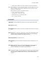
The status bar, at the bottom of the workspace shows the current status of the
application or status of the activity in progress. When Active@ UNDELETE is idle
and ready to perform an operation, the status displays "Ready".
To toggle the status bar on and off, click View > Status Bar.
Note When you run Active@ UNDELETE, the application gathers information about disks
and partitions available to the system. During this preliminary operation, the status
bar displays "Initializing..." and application prevents most other operations from
starting. Application Log View shows detailed information about the initialization
stage.
Application Views and Windows
Many views display lists and hierarchy trees and use symbols to indicate the status
of drives, devices, folders and other items. For descriptions of these symbols, see
Symbols and Icons in the Appendix.
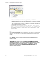
To modify the information displayed in columns in a table list, right-click any
column header and select or clear columns from context menu. If you click More…
in the context menu, the Choose Columns dialog box appears.
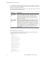
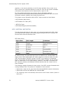
RECOVERY EXPLORER VIEW
The main view in Active@ UNDELETE is Recovery Explorer View. The view tab label
displays “My Computer”.
This is the default view that you see after the application starts. The left panel is
the Tree pane. It displays the hierarchical structure of all drives, devices, folders
and files of the scanned Logical Drive, Virtual RAID and opened Disk Image. Scan
Results appear here if you scan a device. To collapse a node in this tree, click the
minus sign (-) next to the node name or double-click a node. To expand a node,
click the plus sign (+) next to the node name or double-click a node.
When you select a node in the hierarchy tree, details of the selected node appear in
the List pane and Properties panel.
Recovery Explorer View
The List Pane displays the sub elements of the selected node. To make the list
easier to read, you may do the following:
· To sort the list by a column in ascending order, click the column header. The
column is highlighted.
· To sort the same column in descending order, click the column header a second
time.
· To show a list that is reduced in size by a filter, select one of the preset options
in the File Filter toolbar.
6
Active@ UNDELETE 7.0 User Guide
Document View
When you select items in the List pane, details of the selected item appear in the
Properties panel.
To perform an action on any node in either the Tree pane or the List pane, select
the node and choose a command from the View or Tools menus. You may also
choose a command from the toolbar or from the right-click context menu.
To add an item to the Recovery Toolbox, select the check box next to the item.
The Properties panel displays default properties for each selected item in Tree or
List panes. Updates to these properties appear dynamically along with commands
and activities performed in the workspace. To toggle the Properties Pane on and off
click View > Properties Pane.
Note You can create a custom filter for tree and list items. For more information see File
Filter Toolbar in the Appendix.
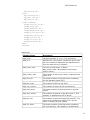
DOCUMENT VIEW
The Document View displays all files detected after a logical drive scan. The left
pane displays a list of items. To make the list easier to read, you may group these
items by:
· Extension
· Application
· File Type
When you select an item in the left pane, all detected files that match the selected
criteria appear in the right pane. To make this list easier to read, you may do the
following:
· To sort the list by a column in ascending order, click the column header.
· To sort the list by the same column in descending order, click the column header
a second time.
· To show a list that is reduced in size by a filter, select one of the preset options
in the File Filter toolbar.
· To add an item to the Recovery Toolbox, select the check box next to the item.
Note You can create a custom filter for this list. For more information see File Filter Bar
in the Appendix.
RECOVERY TOOLBOX VIEW
The Recovery Toolbox is a tool that allows files selected from various other views
(for example Recovery Explorer, Document View or Search Result) to be recovered
at once to the same specified destination. The recovery destination may be a
different Hard Disk or a CD or Data DVD. In the recovery destination, each
recovered file retains a copy of its original folder hierarchy. When you select the
check box next to a file or folder in Recovery Explorer view, Document View or
Search Results View, the selected item is copied to the Recovery Toolbox along with
its path information. Similarly, if you clear a check box next to a file or folder in
another view, the item is removed from the Recovery Toolbox.
7
Application Views and Windows
In the Recovery Toolbox, the Space Indicator panel displays available space on
recovery destination drive or CD/DVD along with the amount of free space required
to recover all selected files.
To clear all selected check boxes in all views, click Clear Recovery Toolbox.
Note Including path information is optional. For more information, see Recovery in
Application Preferences, in this chapter.
LOG VIEW
This log screen monitors each action taken by the application and displays
messages, notifications and other service information. Use the messages in this
screen to observe and further understand the flow of the recovery process.
We recommend that you attach a copy of the log file to all requests made to our
technical support group. The entries in this file will help us resolve certain issues.
To prepare a log file, turn on Display Trace Events and Write Log on Disk options in
the Preferences dialog box.
It is best to save the log file to a physical disk that is different from the disk that
holds the deleted data. By doing this, you reduce the risk of writing over the data
that you are trying to recover.
For information on setting log file options, see Application Preferences in this
chapter.
8
Active@ UNDELETE 7.0 User Guide
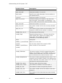
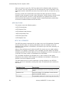
Search Results View
SEARCH RESULTS VIEW
The Search Results view appears after you perform a Search for Files and Folders.
The top panel displays the results of the search in a list.
Search Results View
To make this list easier to read, you may do the following:
· To sort the list by a column in ascending order, click the column header.
· To sort the list by the same column in descending order, click the column header
a second time.
· To show a list that is reduced in size by a filter, select one of the preset options
in the File Filter toolbar.
To add an item to the Recovery Toolbox, select the check box next to the item.
To recover an item in this list, right-click the item and choose Recover from the
context menu.
To preview an item, select it and click File Preview.
The Search Details panel shows the statistics and criteria of the search that was
recently performed. To show or hide this panel, click Information.
To change search criteria and repeat the search at the same location, click Search
Again.
To close the Search Results view and discard all information, click Close.
9
Application Preferences
Note: For information about how to start a search, see Search for Files and Folders in
Chapter 3. Using Active@ UNDELETE 7.0.
Note: You can create a custom filter for this list. For more information see File Filter Bar
in the Appendix.
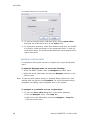
APPLICATION PREFERENCES
You can change many of the settings that affect the application's behavior in the
Preferences dialog box.
To open the Preferences dialog box, do one of the following:
· From the Tools menu, select Preferences
· In the Application toolbar, click Preferences
A description of the tabs in this page follows below.
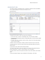
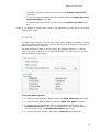
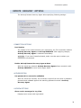
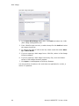
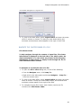
GENERAL
To set General options:
1. You may set default activities that happen when the application starts or exits:
· To show a warning before saving the current session when you exit, click Ask
before exit.
· To save the session without a warning when you exit, select Autosave
without prompt.
· To exit each time without saving, select Exit without saving.
· To load the previous session data each time you start, select the Autoload
last saved session check box.
10
Active@ UNDELETE 7.0 User Guide
Search Results View
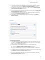
2. To connect to the Active@ UNDELETE site and check for application updates
each time you start, select the Check for available updates check box.
3. To display the property panel each time you start, select the Show Property
Panel for Files and Folders check box.
4. To show hints about the application each time you start, select the Show Hint
dialog at application start check box.
5. To automatically skip over bad sectors when scanning the disk or recovering
files, select the Ignore bad sectors check box.
6. To discard all custom General settings and restore defaults, click Restore
default settings.
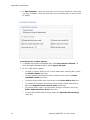
RECOVERY
To set Recovery options:
1. To set the default path to the folder where you will save recovered files, enter
the path in the Default path to recover field. You may also click the ellipsis
button (…) and navigate to this folder.
2. To automatically replace invalid characters in a recovered file name:
a. Select the Replace invalid file name symbols check box.
b. Enter a valid character in the field. The standard character is underscore
(_).
3. To save recovered files and folders on the same drive as the source data, select
the Allow to recover to the same drive check box.
4. To open the destination folder after you recover files and folders, select the
Open destination folder check box.
11
Application Preferences
5. To automatically skip over bad sectors when recovering a file, select the
Ignore bad sectors check box.
6. When you restore a partition, to automatically save a backup file before you
restore:
a. Select the Backup Partition Information check box.
b. Enter the path and the default file name for the backup file in the File
name field. You may also click the ellipsis button (…) and navigate to the
folder and then enter the file name.
Note: We strongly recommend that you do not write recovered files and folders to the
same hard drive as the source data.
TOOLS
To set Tools options:
1. In File Preview:
·
To attempt to preview an image file each time you select a new file, select
the File Preview follow-up check box. To attempt to preview an image file
manually each time, clear this check box.
·
To show non-image files in the image viewer in hexadecimal mode, from the
Number of columns in hexadecimal mode drop-down list, select the
number of columns.
2. In Application Log:
· To show the Application Log view when you start, select the Show Log
Window at Start check box.
12
Active@ UNDELETE 7.0 User Guide
Search Results View
· To record all system events in the log, select the Display Trace Events
check box.
· To show recovery messages from the system, select the Display Recovery
Kernel Messages check box.
· To automatically write the log to a file, select the Write log on disk check
box.
Note: If you display all system trace events in the application log, the log file will quickly
become very large.
HEX EDITOR
Hex Editor uses a simple, low-level disk viewer which displays information in binary
and text modes at the same time. You can use this view to analyze the contents of
data storage structure elements.
The Data Inspector is part of the Hex Editor and displays whatever is currently
under the cursor. It does so in ten different formats. This may help you interpret
data as displayed in Hex Editor.
To set Hex Editor options:
1. To show the Status pane by default, select the Show Status pane check box.
2. To show the Info pane by default, select the Show Info pane check box.
3. To display the current address offset in Hexadecimal format, select the
Hexadecimal address check box. To display the current address offset in
decimal format, clear the Hexadecimal address check box.
4. To set the font size, choose a size from the Font size drop-down list.
13
Application Preferences
5. In Data Inspector, select the check box next to all the formats of values that
you want to display. Clear the check box next to formats that you do not want
to display.
RECOVERY TOOLBOX
To set Recovery Toolbox options:
1. To display the file path of selected files, select Reconstruct Full Path. To
leave the path information blank, select Ignore file path.
2. In CD – DVD burner options:
14
·
To allow no further writing to CD or DVD media after restoring files, select
the Finalize Media check box.
·
To wipe erasable media before writing restored files, select the Erase
rewritable media check box.
·
To set the cache buffer size, enter a size in the Cache buffer size field.
·
To monitor and maintain the quality of disc writing (newer disc writers)
select the Dynamic Power Control (OPC) check box.
·
To prevent buffer under run errors when writing to CD/DVD, select the
Buffer Under RuN Error Proof check box.
·
To eject the CD/DVD after burning, select the Eject disk after burning
check box.
Active@ UNDELETE 7.0 User Guide
Scan a Physical Device for Deleted Partitions
3. USING ACTIVE@ UNDELETE 7.0
Note: Not every deleted file can be recovered. To be successful, it is important to try
every method available.
RESTORE PARTITIONS
If you cannot see partitions on your device, or if you know that partitions are
missing, you may scan a device to find partitions first.
If you can see partitions on your device, you may skip ahead to Recover Files and
Folders.
SCAN A PHYSICAL DEVICE FOR DELETED PARTITIONS
A physical device is an installed hard disk, Flash card, external USB disk or any
device that holds data. You may scan a device two ways:
· Scan for deleted partitions.
· Scan for files by signature.
SCAN FOR DELETED PARTITIONS
You can locate existing and deleted partitions on a physical device.
15
Restore Partitions
To scan a physical device for deleted partitions:
1. In the Recovery Explorer tree, select a device node under Data Storage
Devices. Details of the selected node appear in the List pane.
2. To open the Disk Scan dialog box, do one of the following:
· In the Recovery Explorer Toolbar, click Default Scan.
· Right-click the selected device and click Scan > Deleted Partitions from the
context menu.
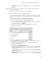
3. In the Disk Scan dialog box, you may:
· Select specific areas to scan or you may scan the entire disk.
·
If you select specific areas to scan, use sliders or exact numbers to set
boundaries of scan area.
· Set the scan type to Fast, Normal or Advanced.
· Search for default patterns, or you may select specific patterns to search for.
4. Click Scan. The Processing… dialog box appears.
5. To display scanning events and progress details, click Details.
6. To terminate the scan process, click Stop at any time. Results may be not
accurate or complete.
7. After the scan completes or terminates, a Scan Results branch appears in the
Recovery Explorer tree.
Note: If you stop a device scan before it has completed, you may resume the scan from
the point at which it was terminated.
You may use nodes in the Scan Results branch for further actions. For more
information, see Using Scan Results later in this chapter.
16
Active@ UNDELETE 7.0 User Guide
Filter Detected Partitions by Certainty
SCAN FOR FILES BY SIGNATURE
You can locate current and deleted files by their unique file signature on a physical
device.
To scan for files by signature:
1. In the Recovery Explorer tree, select a device node under Data Storage
Devices. Details of the selected node appear in the List pane.
2. To open the Low Level Disk Scan dialog box, do one of the following:
· From the Recovery Explorer toolbar, click Advanced Scan.
· Right-click the selected device and click Scan > Low Level from the context
menu
3. In the Low Level Disk Scan dialog box, you may:
· Select specific areas to scan or you may scan the entire disk.
·
If you select specific areas to scan, use sliders or exact numbers to set
boundaries of scan area.
· Select Options to add or remove file signatures to search for.
4. Click Scan. The Processing… dialog box appears.
5. To display scanning events and progress details, click Details.
6. To terminate the scan process, click Stop at any time. Results may be not
accurate or complete.
7. After the scan completes or terminates, a Scan Results branch appears in the
Recovery Explorer tree.
Note: If you stop a device scan before it has completed, you may resume the scan from
the point at which it was terminated.
You may use nodes in the Scan Results branch for further actions. For more
information, see Using Scan Results later in this chapter.
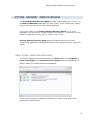
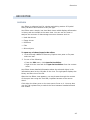
FILTER DETECTED PARTITIONS BY CERTAINTY
After you complete a scan, detected partitions are listed in order of their certainty
status based on attributes and validation level. To make a long list of partitions
easier to read, remove partitions with status Bad and lower using a filter.
To filter detected partitions:
1. In the Scan Results node, select a device node with detected partitions.
2. To open the Filter Detected Partition dialog box, do one of the following:
· From the Recovery Explorer toolbar, click Filter DeviceScan Results.
· Right-click the partition and click Filter… from the context menu.
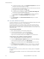
3. In the Filter Detected Partition dialog box, do the following:
a. To filter any file systems, select the Any File Systems check box.
17
Restore Partitions
b. To specify file systems to filter, select Specify File Systems and select the
check box next to all file systems to include.
c. To reduce the size of the partition list, select the check box only next to the
status settings that you want to display.
d. To display any size of partition, click Any Size.
e. To restrict the size of partition to display, click Specify Size Range, KB
and enter the lowest and highest partition size.
f. To set advanced filter options, click Advanced and indicate each FAT or
NTFS attribute in the Advanced Filtering dialog box appears.
4. Click OK.
5. Press Set Defaults in the Filter Detected Partition dialog box to cancel
partition filtering.
EDIT OR CLONE DETECTED PARTITIONS
It may be necessary for you to edit detected partition attributes directly when some
attributes are detected incorrectly or need adjustments.
Any detected partition can be cloned (virtually copied) before manually altering
partition attributes and properties. We recommend that you edit the clone rather
than directly edit the original partition. Any detected partition can be cloned as any
times as you want.
To clone detected partitions:
1. Select a detected partition in the Recovery Explorer tree.
2. To clone the selected partition, do one of the following:
· From the Recovery Explorer toolbar, click Clone Partition.
· Right-click the selected partition and click Clone from the context menu.
To edit the boot sector template in detected partitions:
1. Select a detected partition in the Recovery Explorer tree.
2. To open the Edit Boot Sector Template dialog box, do one of the following:
· From the Recovery Explorer toolbar, click Edit Partition.
· Right-click the selected partition and click Edit Partition from the context
menu.
3. In the Edit Boot Sector Template dialog box, edit the Primary or Copy Boot
sectors separately or simultaneously by entering values in designated fields.
RESTORE PARTITIONS
We recommend that you restore a partition with a certainty status of “Acceptable”
or higher).
Before you restore a partition, you may clone or edit the partition directly to adjust
its properties.
18
Active@ UNDELETE 7.0 User Guide
Restore Partitions
Here are some rules to follow when restoring a partition:
1. Assigning a drive letter.
· Be aware of the location of executable files or files required by the operating
system. Many MS-DOS and Windows programs refer to a specific drive letter
when describing a path to executable files.
· Drives A: and B: are usually reserved for floppy disk drives, but you can
assign these letters to removable drives if the computer does not have a
floppy disk drive.
· Hard disk drives in the computer receive letters C through Z, while mapped
network drives are assigned drive letters in reverse order (Z through B).
2. Setting the partition as active.
· You may set only a primary partition as active. You cannot set a logical drive
(an extended partition) as active.
· To set a partition as active, the partition must have an MBR (Master Boot
Record) as the first sector.
· A computer can only have one active partition per disk.
· The name commonly used for the partition that contains the startup files is
the boot partition. The name commonly used for the partition that contains
the operating system files is the system partition.
· The system partition can never be part of a striped volume, spanned volume,
or RAID-5 volume
· The system partition must be a primary partition that has been marked as
active for startup purposes. It must be located on the disk that the computer
accesses when starting up the system.
· There can be only one active system partition on a disk at a time.
· You may have multiple basic disks and each disk can have one active
partition, however the computer will only start from one specific disk. If you
want to use another operating system, you must first mark its system
partition as active before restarting the computer.
· You cannot mark an existing dynamic volume as active. However, you can
convert a basic disk containing the active partition to a dynamic disk. After
the disk is converted, the partition becomes a simple volume that is active. If
the active partition is not the current system or boot partition it becomes a
simple volume and loses its entry in the partition table, so it can no longer be
active.
3. Creating an extended partition.
· A computer can only have one extended partition per physical disk device.
· You cannot create an extended partition on a disk if it already has four
primary partitions.
To restore a detected partition:
1. Select a detected partition in the Recovery Explorer tree.
19
Restore Partitions
2. To open the Restore Partition dialog box, do one of the following:
· From the Recovery Explorer toolbar, click Restore Partition.
· Right-click the selected partition and choose Restore Partition from the
context menu.
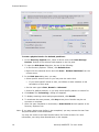
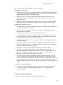
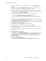
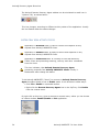
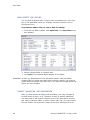
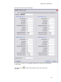
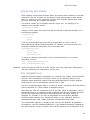
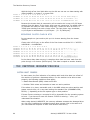
Restore Partition Dialog Box
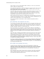
3. In the Restore Partition dialog box, specify options for recovery:
· To select a different partition from the Device Scan without exiting this dialog,
select one from the list. The selected partition appears on the device map,
showing its relative position and size.
· A selected partition that appears on the device map with a green border fits
the unallocated space and can be recovered.
· If the selected partition appears with a red highlight, then this partition
overlaps with an existing partition and cannot be restored.
· To assign a drive letter to the recovered partition, select a letter from the
Assign the following drive letter drop-down list.
· To set this partition as active, select the Set partition active check box.
· To save partition information to a file for safety or for reference, select the
Backup Partition Information check box and enter the path and file name
in the File name field. To browse to the folder and record the path, click the
ellipsis button (…).
20
Active@ UNDELETE 7.0 User Guide
Scan a Logical Drive
· To create an extended partition, select the Create Extended partition check
box.
· To automatically verify and correct the boot sector, select Auto.
· To verify and correct boot sectors records manually in a dialog box, select
Manual.
RECOVER FILES AND FOLDERS
After you can see partitions on a device, the UNDELETE process consists of two
stages.
· Stage 1 – Scan a logical drive
· Stage 2 – Search for deleted files and folders
· Stage 3 - Recover deleted files and folders
SCAN A LOGICAL DRIVE
Scanning logical drives is a required step for recovering files and folders – during
the scan all deleted (and existing) file and folders are detected. There are two ways
to scan a drive or a partition:
· Quick Scan – quick and sufficient in most scenarios.
· Low Level Scan - where files will be detected by a unique file signature.
QUICK SCAN
Quick Scan results are displayed in folders under the scanned drive node in
Recovery Explorer and, optionally, in Document View.
To Quick Scan a logical drive:
1. In the Recovery Explorer tree pane or in the list pane, select a logical drive.
2. To open the Scan Logical Drive dialog box, do one of the following:
· From the Recovery Explorer toolbar, click Default Scan.
· Right-click the selected logical drive and click Scan from the context menu.
3. Choose Quick Scan.
4. To collect scan results in the Document View, select the Show scan results in
Document View check box.
5. Click Scan! The Processing… dialog box appears.
6. To display scanning events and progress details, click Details.
7. To terminate the scan process, click Stop at any time. Results may be not
accurate or complete.
8. After the scan completes, if you chose to show scan results in the Document
View, the Document View appears.
21
Recover Files and Folders
9. To view hierarchical folders under the scanned drive node, select the My
Computer tab. The Recovery Explorer view appears. The node label for the
logical drive that was scanned is emphasized in bold.
For help with locating files in the Document View, see Application Views and
Windows in Chapter 2. Getting Started.
LOW LEVEL SCAN
Low Level Scan results are displayed under a Scan Results node in Recovery
Explorer. All found files are grouped by their file extension.
You may rescan logical drives as many times you want. All previous results will be
lost and each scan result may vary.
A Low Level Scan is a more complex process and will take more time than a Quick
Scan. You may save Low Level Scan results in a separate file and reuse the results
in a new session.
To Low Level Scan a physical device or a logical drive:
1. In the Recovery Explorer tree pane or in the list pane, select a physical device
or a logical drive.
2. To open the Scan Logical Drive(s) dialog box, do one of the following:
· From the Recovery Explorer toolbar, click Default Scan.
· Right-click the selected logical drive and click Scan from the context menu.
3. Choose Low Level Scan.
4. To modify list of file signatures to be searched:
g. Click Options. The Select File Signatures dialog box appears.
h. To restrict the search parameters, clear the check box next to each file type
that you do not want to search for.
i. Click OK.
5. View the list of file signatures that will be reported in the File Signatures text
box.
6. Click Scan! The Processing… dialog box appears.
7. To display scanning events and progress details, click Details.
8. To terminate the scan process, click Stop at any time. Results may be not
accurate or complete.
9. After the scan completes, scan results appear in a Scan Results node in
Recovery Explorer.
To save Low Level Scan results:
1. Under the Scan Results node, right-click a scanned logical drive and click
Save Scan Result from the context menu. The Save Scan Result dialog box
appears.
2. Browse to the folder where you want to save the file.
22
Active@ UNDELETE 7.0 User Guide
Search for deleted Files and Folders (Optional)
3. In File name, you may use the suggested file name, or you may change it.
4. Click Save.
WARNING: Save a scan results file to a physical drive that is different from the drive that
contains the original files.
After you have completed your scan, continue with Stage 2.
SEARCH FOR DELETED FILES AND FOLDERS (OPTIONAL)
To help you find deleted files in a long list of files from a scanned drive, you may
search the list with specific search criteria and review results in a Search Results
View.
To search a scanned drive for deleted Files and Folders:
1. Select a scanned Logical Drive or scanned Detected Partition.
2. To open the Search for Files and Folders dialog box, do one of the following:
· From the main toolbar, click Search.
· Right-click the selected item and click Search from the context menu.
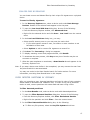
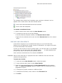
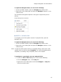
Search for Files and Folders Dialog Box
3. In the Look for field, enter the text, along with wildcard symbols or regular
expressions, for which you intend to search.
4. The search path appears in the In field. To change the search path, click
Browse… and select the drive.
5. To set options in the General Criteria tab:
· To search the root level of the drive and all sub folders, select the Recursive
search in subdirectories check box. To search only the root folder, clear
this check box.
· To display only files that are deleted or damaged, select the Search among
deleted only check box.
· To display only files that are not deleted, select the Search among existing
only check box.
23
Recover Files and Folders
· To display files that match upper and lower case letters in the Look for field,
select the Match casecheck box.
6. To display files by a specified date, in the Date Criteria tab, in the Date Type
drop-down list, choose a type and select a date range.
7. To display files by a specified file size, in the Size Criteria tab, select Small,
Medium or Large, or specify the size range in KB.
8. To display files based on file attributes, in the File Attributes Criteria tab, click
Selected Attributes Only and select the check box next to all attributes that
you want to search for.
9. To change all settings back to default settings, click Set Defaults.
10. Click Search Now. The Processing… dialog box appears.
11. To display disk image events and progress details, click Details.
12. To terminate the disk image process, click Stop at any time. Results may be
not accurate or complete.
13. After the search is complete, a Search Results view appears.
You may repeat a search many times and refine the search criteria for better
results.
Note: The search pattern wildcard symbols use the same pattern that you use when
searching in Windows.
The asterisk (*) in the pattern means that at this place can be zero or any other
symbol. For example:
· *
- all files on the drive or in the folder
· *.TXT
- all files with "TXT" extension
· My*.*
- all files starting with "My"
· MyFile.txt - search for the file named "MyFile.txt"
For information about the Search Results view, see Application Views and Windows
in Chapter 2. Getting Started.
You may use File Filter to improve search results. For more information see File
Filter Toolbar in the Appendix.
RECOVER FILES
Recovering deleted files and folders is one of essential features of Active@
UNDELETE. There are two main methods for recovering detected files and folders:
· Recover from application views. Recovery Explorer, Document View and
Search Result Views display files, which you can recover directly from the view.
· Recover using the Recovery Toolbox. You may collect files and folders in the
Recovery Toolbox from various sources and recover them all at once.
WARNING: Save recovered files or folders onto a different drive from where the original
damaged or deleted files or folders exist.
24
Active@ UNDELETE 7.0 User Guide
Recover Files
RECOVER FROM APPLICATION VIEWS
You may recover damaged or deleted files and folders directly from Recovery
Explorer, Document View and Search Result View.
To recover files from views:
1. In the view list, click a file or folder to select it.
2. You may select multiple files or folders.
· To select consecutive files or folders in a list, select the first item and press
SHIFT while you select the last item.
· To select non-consecutive files or folders, select the first item and press CTRL
while you select each other item.
3. To open the File and Folder Recovery dialog box, do one of the following:
· From the Recovery Explorer toolbar, click Recover Files and Folders.
· Right-click selected files and click Recover from the context menu.
4. In the File and Folder Recovery dialog box, specify the destination path to
save recovered files and other options and click Recover. The Processing…
dialog box appears.
5. To display recovery events and progress details, click Details.
6. To terminate the recovery process, click Stop at any time. Results may be not
accurate or complete.
RECOVER USING THE RECOVERY TOOLBOX
You can select files from different views in the Active@ UNDELETE workspace and
collect them in the Recovery Toolbox. To select files, select the check box next to
the file name in Recovery Explorer, Document View or Search Results view. To
remove files from the Recovery Toolbox, clear the check box in these three views.
You may recover the collection of files and folders in the Recovery Toolbox all at
once. There are two methods for recovering files:
· Recover files to a hard disk.
· Recover files to a CD or DVD.
To recover files to a hard disk:
1. To collect files in the Recovery Toolbox, select the check box next to the file
name or folder name in Recovery Explorer view, Document View or in
Search Result view. Folder hierarchy for selected files are preserved in the
Recovery Toolbox.
2. Select the Recovery Toolbox tab.
3. Click Recover all items in Recovery Toolbox. The File and Folder
Recovery dialog box appears.
4. In Destination path, enter the path to the folder where you want to save
recovered files. To browse to the folder and record the path in this field, click
the ellipsis button (…).
25
Recover Files and Folders
5. To use the same file name for each recovered file, click Use original file
names.
6. To rename each file, click Rename files to and enter a file name prefix. Each
file will be named with this prefix and a sequential number.
7. If you are writing recovered files back to the same folder where the original
files were, you might encounter existing files with the same name. Decide what
to do in each case in If file already exist.
8. To automatically replace invalid characters in a recovered file name:
j. Select the Replace invalid file name symbols check box.
k. Enter a valid character in the field. The standard character is underscore
(_).
9. To save recovered files and folders on the same drive as the source data, select
the Allow to recover to the same drive check box.
10. To display the destination folder after recovery, select the Browse destination
folder after recovery completes check box.
11. Click Recover. The Processing… dialog box appears.
12. To display recovery events and progress details, click Details.
13. To terminate the recovery process, click Stop at any time. Results may be not
accurate or complete.
14. If you chose to display the destination folder after recovery, the destination
folder appears.
To recover files to a CD or DVD:
1. To collect files in the Recovery Toolbox, select the check box next to the file
name or folder name in Recovery Explorer view, Document View or in
Search Result view. Folder hierarchy for selected files are preserved in the
Recovery Toolbox.
2. Select the Recovery Toolbox tab.
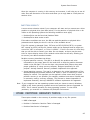
3. Click Burn. The Burn Files and Folder on CD\DVD dialog box appears.
26
Active@ UNDELETE 7.0 User Guide
Recover Files
Burn Files and Folders on CD\DVD Dialog Box
4. To change the volume label on the CD, enter the label in Volume label.
5. To select another burning device, choose it in the Burn to drop-down list.
6. To burn an ISO image:
a. In the Burn to drop-down list, choose ISO Image. The ISO File Name
field appears.
b. Enter the path to the folder where the ISO image will be created. To browse
to the folder, click the ellipsis button (…).
7. Specify burning options and file date preferences.
8. Click Burn! The Processing… dialog box appears.
9. To display recovery events and progress details, click Details.
10. To terminate the recovery process, click Stop at any time. Results may be not
accurate or complete. The disk will likely be unreadable, if you stop.
For a description of burning options in the Recovery Toolbox, see Application
Preferences in Chapter 2. Getting Started.
27
Using Scan Results
USING SCAN RESULTS
The information in this chapter can be used for either a physical device scan or for
a logical drive or partition scan.
After you have completed a device scan, a Scan Results branch appears in the
Recovery Explorer tree. Detected partitions are listed in order of their certainty.
Scan Results Display Order of Certainty
There are 12 attributes that define a partition. In some cases, the application
cannot be certain that the found item actually is a partition. The rating in the order
of certainty depends on how many attributes are found and what condition they are
in.
You may perform the following actions on partitions in the Scan Results branch:
· Stop and Resume a Scan
· Save and Load Scan Results
· Restore Scan Results
STOP AND RESUME A SCAN
To stop a physical device scan at any time, press Stop. After you stop a scan, a
Scan Results branch appears in the Recovery Explorer tree.
28
Active@ UNDELETE 7.0 User Guide
Save and Load Scan Results
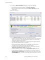
Example Stopped Scan Results
The example above shows how incomplete scan results are indicated. An icon
appears next to each node in the Scan Results branch.
- Device scan was terminated and can be resumed
- Device scan was completed
To resume a terminated scan:
1. Select a device scan result under the Scan Results branch.
2. To resume the scan, do one of the following:
· From the Recovery Explorer toolbar, click Resume Device Scan.
· Right-click the selected device scan and click Resume Scan from the context
menu.
SAVE AND LOAD SCAN RESULTS
It can take a long time to run a Default Disk Scan or a Low Level Disk Scan.
Because you are dealing with a large volume of information, you might not be able
to review all the data in one session.
So that you do not have to scan a partition again, you can save and re-use valuable
scan results. You can save entire Scan Results branch
or make separate save
for each Disk Scan or all scan set for particular device.
Scan results are saved with the file extension SCANINFO.
WARNING: Save a scan results file to a physical drive that is different from the drive that
contains the original files.
To save scan results:
1. To save the entire Scan Results branch, select the branch.
2. To save a device node, select it under Scan Results.
3. Right-click the selected node and click Save Scan Result from the context
menu. The Save Scan Result dialog box appears with the default path and a
suggested file name.
4. To change the file path, browse to a different folder.
5. To change the file name, enter a name in the File name field.
6. Click Save.
29
Using Scan Results
To load saved scan results:
7. To open the Load Scan Results dialog box, do one of the following:
· From the File menu, click Open > Scan Result…
· Right-click the logical drive node and click Load Scan Result from the
context menu.
· If there is a Scan Results branch in the Recovery Explorer tree, right-click
the Scan Results branch or right-click a Scan Results node and click Load
Scan Result from the context menu.
8. Browse to the folder that contains the scan result file and select the file.
9. Click Open.
The data from the scan results file appears in a Scan Results node in the Recovery
Explorer tree.
REMOVE SCAN RESULTS
Data in the Scan Results branch is copied from the original physical device. You
may remove any node – including detected partitions - from the Scan Results
branch without harming the data on the original physical device.
To remove scan results:
1. To remove the entire Scan Results branch, select the branch.
2. To remove a device node, select it under Scan Results.
3. Right-click the selected node and click Remove Scan Result from the context
menu.
The selected node is removed from the Recovery Explorer tree.
30
Active@ UNDELETE 7.0 User Guide
Establish the connection to remote computer
4. ACTIVE@ UNDELETE – ENTERPRISE EDITION
Active@ UNDELETE Network Edition allows application ("Client") to connect to the
remote computer ("Server") by using Active@ Remote Recovery Agent and:
· Scan drives and devices
· Search for Files and Folders
· Preview deleted Files
· Recover deleted Files and Folders on remote machine and much more...
The remote computer must be running the Active@ Remote Recovery Agent to let
the host computer to get access to its file structure. After establishing the
connection, you can navigate through drives and folders of the remote computer in
the same way that it works for a local computer.
CONNECT TO ACTIVE@ REMOTE RECOVERY AGENT
If you are using the Active@ UNDELETE Enterprise Edition you be able to connect to
Active@ Remote Recovery Agent to recover files on (from) remote computer.
Active@ Recovery Agent is a small utility that provides recovery features over a
network environment.
The computer that you want to connect to must have Active@ Remote Recovery
Agent running with status Enabled. After you establish connection through the
network, then you can scan and browse the Files and Folders of the remote
computer and select them for recovery. You can recover files locally (copy
recovered files from remote computer to the one where Active@ UNDELETE is
running) or remotely, e.g. recovered files will be stored on a computer where they
were actually recovered.
ESTABLISH THE CONNECTION TO REMOTE COMPUTER
1. Open Connect to Active@ Remote Recovery Agent dialog in one of the
following ways:
· From the Files menu choose Connect... command.
· From the Recovery Explorer toolbar, click Connect button.
31
Connect to Active@ Remote Recovery Agent
2. In Connect to Active@ Remote Recovery Agent dialog do the follows:
· Select a workstation from a drop-down list of network neighborhood computer
names or
· Type a computer name or computer IP address or a name into the combo box
text field and press [Enter] to connect.
3. Click Connect button to establish connection with Active@ Remote Recovery
Agent on computer you selected. Once connection is set, you will be able to see
Physical Disks and Drives of remote compuer ready to be scanned for deleted
Files and Folders.
Note:
Click Browse for Computer button, located on the right side of the neighborhood
computers drop-down list, to find and choose computer outside of workgroup or
domain;
Click Options... button to change connection options. See Remote Recovery
options for details.
WARNING: If the remote computer has Active@ Remote Recovery Agent
protected with a password, you will need to specify the same password in Remote
Recovery Options to be able to make connection. If the password you enter
matches the password defined for Active@ Remote Recovery Agent the
connection will be established.
32
Active@ UNDELETE 7.0 User Guide
Using Active@ Remote Recovery Agent
ACTIVE@ RECOVERY AGENT OVERVIEW
The Active@ Remote Recovery Agent provides unique ability (as a "server") to
let Active@ UNDELETE application (act as a "client") to do remote scan, search,
recover and other operations with remote computers.
This is very simple to use Active@ Remote Recovery Agent: run it as an
application (you can keep it as open window or minimize it, - in that case you can
access the application at any time in "System Tray" area).
Active@ Remote Recovery Agent has a few options that you can use to
configure the application in appropriate manner. See Remote Recovery options for
details.
USING ACTIVE@ REMOTE RECOVERY AGENT
To start the application from the Windows click Start button, click Programs >
LSoft Technologies. Click Remote Recovery Agent from the programs menu.
When it starts, the window shown below appears:
In this Log View screen, transaction information is shown, along with a brief
description of each activity.
33
Active@ Recovery Agent Overview
The Active@ Remote Recovery Agent window can be minimized to small icon in
"System Tray" as shown below:
This icon changes, according to different activity states of the application. Usually
the icon flashes when the status changes.
SYSTEM TRAY ICON ACTIVITY STATES
Application in Disabled state. It cannot receive and response on any
request from Active@ UNDELETE Client.
Application in Enabled state. It ready to receive and response on any
request from Active@ UNDELETE Client.
Application in Connected state. It currently on line with Recovery
Toolkit Client and processing scanning, recovery and other commands
from the client.
This icon indicates, that Active@ Remote Recovery Agent
processing requests from Active@ UNDELETE Client. Usually it
flashes also when change the status.
To let Active@ UNDELETE ("client") to connect to Active@ Remote Recovery
Agent its status should be set to Enable mode. It can be done in either ways:
· Click File > Enable in command toolbar.
· Right-click the Remote Recovery Agent icon in the SysTray. Click Enable
from the context menu.
By right click on this icon, gives an access to context menu, where you can choose
to restore window, Enable\Disable or Exit application.
34
Active@ UNDELETE 7.0 User Guide
Connection options
REMOTE RECOVERY OPTIONS
The Active@ Remote Recovery Agent allow specifying following settings:
CONNECTION OPTIONS
Port Number
The number of the communication port reserved for the TCP connection between
Active@ Recovery Agent and Active@ UNDELETE. After applying changes,
Active@ Recovery Agent is restarted immediately.
WARNING: If you have firewall activated, make sure that ports numbers you
selected are not blocked.
Enable Active@ Remote Recovery Agent at Start.
With this check box selected, Active@ Recovery Agent allows connection with
Active@ UNDELETE as soon as the agent starts.
AUTHORIZATION
Use password for connection validation
With this check box selected, the connection request from the client is password
protected and validated against the matching password entered in Active@
Recovery Agent.
LOGVIEW OPTIONS
Show service messages in Log View
Display traces events with high details
35
Remote Recovery Options
Auto-save log entries
With this option on, all events will be saved in log file on disk, by default, in
directory where Active@ Recovery Agent is installed.
36
Active@ UNDELETE 7.0 User Guide
5. ACTIVE@ UNDELETE TOOLS
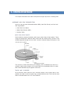
DISK IMAGE
With Active@ UNDELETE you can create a raw Disk Image of logical
drives and part of or a whole physical data storage device. A raw Disk
Image contains an exact, sector-by-sector copy of a single partition or
disk.
A raw Disk Image consists of two files: a configuration file and data file
(or files). The configuration file describes the disk or partition geometry
and keeps the image description. This file has the .DIM extension. When
verifying or exploring a raw image, select this file.
The raw Disk Image data files have numerical extensions starting from
.001 added to the whole image name.
Here is an example: If you save a raw disk image with the name
MyImage, the application creates a file named MyImage.dim. This is the
configuration file. Data is stored in a file named MyImage.dim.001. If
more than one file is created, the next file is named MyImage.dim.002,
and so on.
The data file can be split in several files – chunks that can be useful if you
want to save the Disk Image on a CD or Data DVD.
WHEN TO USE DISK IMAGE
Raw disk images are very helpful in a data recovery. Here are some
reasons why a raw disk image can be used for data recovery:
· Data recovery technologies are based on searching the unused space
on a partition for traces of deleted, lost or damaged files and folders.
So-called "unused space" on a partition is not recognized by the file
system and is not saved to a regular disk image. However, this space
does contain valuable data information and it is saved to a raw disk
image.
· The uncompressed raw disk image file contains a sequence of sectors
that is unchanged from the original. There are no headers or other
application-specific identifiers added. As a result, the raw disk image
can be viewed by any data rescue software as a mirror of your drive. If
the integrity of the data on your live disk is questionable, you may
want to experiment with the data on the partition image instead.
· If file size is an issue, a compressed raw image may be used. Active@
Undelete is an example of data recovery software which can work with
both compressed and uncompressed raw images.
· Raw images have no regard for the file system type. During the raw
disk image recording process, all sectors are backed up. An image of
any partition can be restored by using Active@ Disk Image software.
Disk Image
· If you want the data from a file to be restored from the disk image to
the same exact location as they were before, then use a raw disk
image. A regular image saves all current data but restores files to
different sectors, allowing the partition to shrink or grow, depending
on the size of the replaced file. In a regular situation, you should not
be concerned about partition size. If the partition size is important,
however, a raw image is the solution.
CREATE A DISK IMAGE
Using Active@ UNDELETE you can create a Disk Image of a logical Drive
or a Physical Device.
To create a Disk Image:
1. In Recovery Explorer, select a logical drive, a partition or a physical
device.
2. To open the Create Disk Image dialog box, do one of the following:
· From the Tools menu, choose Disk Image > Create.
· From the Recovery Explorer toolbar, click Create Disk Image.
· Right-click the selected item and click Create Disk Image from the
context menu.
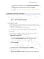
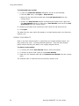
Create Disk Image Dialog Box
3. In the Create Disk Image dialog box, do the following:
· To change the selected disk, choose one from the Disk drop-down
list.
· To specify an area to image, click Select. The Select Disk Area
dialog box appears. Indicate the first and last sectors and click OK.
· Enter the path to the destination folder in Destination path. To
browse to the path, click the ellipsis button (…). If the disk image is
saved in chunks, all chunk files will be created in the same folder.
· Enter a brief description about this disk image for future reference.
38
Active@ UNDELETE 7.0 User Guide
Open a Disk Image
· To split the disk image into files of a specific size, select the Store
Disk Image as chunks of size check box and select the size from
the drop-down list.
· To lock the selected disk and prevent any read or write activity
during the disk image, select the Use Disk Lock check box.
· Indicate the disk compression level. To make the disk image
compatible with any third party applications, choose None [Raw
Data].
4. Click Create. The Processing… dialog box appears.
5. To display disk image events and progress details, click Details.
6. To terminate the disk image process, click Stop at any time. Results
may be not accurate or complete. The disk image will likely be
unreadable, if you stop.
Note: The file extension for a Disk Image configuration file is .DIM by default.
Important: The Destination Path for a Disk Image file must always be on another
drive.
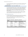
File systems such as FAT16 and FAT32 do not support file sizes larger
than 2GB and 4GB respectively. With these file systems it is not possible
to create a Disk Image file for a drive as it is likely to grow larger than
the size limit. The solution in this case is to do one of the following:
· Use a Destination Path drive that is formatted using Windows NT,
Windows 2000, Windows XP and using NTFS
· Create a Disk Image that is split into chunks of an appropriate size,
keeping within the limits set by the file system
OPEN A DISK IMAGE
You may open a Disk Image to browse for files and folders or to scan for
deleted files and folders.
To open a Disk Image file:
1. To open the Open Disk Image dialog box, do one of the following:
· From the Tools menu, choose Disk Image > Open…
· From the main toolbar, click Open Disk Image.
39
Disk Image
Open Disk Image Dialog Box
2. In the Open Disk Image dialog box, click Load and select the .DIM
(Disk Image Configuration) file.
3. If the .DIM file does not exist, to add a binary file click Add and select
the image chunk files.
4. To change the order of a file in the list, select it and click either Move
Up or Move Down.
5. If you are opening a disk image from a .DIM file, values in Disk Image
Geometry appear.
6. If you are opening a disk image from binary files, click Set Default.
values in Disk Image Geometry appear.
7. Click Open. A node appears in Recovery Explorer.
You may perform all tasks on this node that are applicable for a drive, a
device or a partition.
40
Active@ UNDELETE 7.0 User Guide
Open a Disk Image
WORKING WITH A CORRUPTED RAID SYSTEM
If you have a corrupted RAID configuration and one or more drives in the
array are damaged, you can combine the healthy drives together with the
damaged drives in a virtual disk array. If the damaged drives are
inaccessible, you can substitute a "dummy" drive as a replacement.
Active@ UNDELETE simulates the RAID assembly and you can scan this
virtual array as a logical device.
To create a Virtual Disk Array:
1. To open the Virtual Disk Array Assembly dialog box, do one of the
following:
· From the Tools menu, choose Virtual Disk Array (RAID).
· From the main toolbar, click RAID.
Virtual Disk Array Assembly Dialog Box
2. Specify the virtual array type.
3. To select disks, do one of the following:
· Double-click a disk in the Available disks list to move it to the
Selected disks list.
· Click a disk in the Available disks list to select it. To move it to the
Selected disks list, click Add.
4. To change the order of a disk in the Selected disks list, select it and
click Move Up or Move Down.
5. To remove a disk from the Selected disks list, do one of the
following:
· Double-click a disk in the Selected disks list.
· Click a disk in the Selected disks list. To remove it, click Remove.
6. To remove all disks from the Selected disks list, click Remove All.
41
Virtual Partition (Logical Drive Clone)
7. In Stripe block size, specify the stripe block size in kilobytes (Stripe
and RAID-5 arrays only).
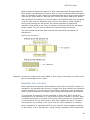
8. If RAID5 is recognized, select a parity layout from the Parity layout
drop-down list.
9. In some cases, you may be able to specify Disk Area to use in
Virtual RAID. To do so, enter the first sector and the area size in
sectors.
10. Click Create. The Processing… dialog box appears.
11. To display creation events and progress details, click Details.
12. To terminate the creation process, click Stop at any time. Results
may be not accurate or complete.
13. If a virtual disk array is created successfully, a new node appears in
Recovery Explorer tree.
14. If a virtual disk array is not created, or if it is created with errors,
return to step 1 and try again with different disks, or with a different
disk order and RAID options.
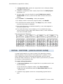
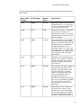
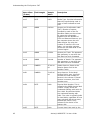
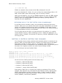
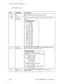
Parity Layout Choices for RAID5 Array
Left
Synchronous
Left
Asynchronous
Right
Synchronous
Right
Asynchronous
0
1
2
P
0
1
2
P
P
0
1
2
P
0
1
2
5
4
P
3
6
P
7
8
P
11
10
9
3
4
P
5
6
P
7
8
P
9
10
11
5
P
4
3
6
7
P
8
11
10
9
P
3
P
4
5
6
7
P
8
VIRTUAL PARTITION (LOGICAL DRIVE CLONE)
A virtual logical partition is a copy (a clone) of a logical drive using a
defined geometry that emulates a real logical drive or partition. If you
have a logical drive that is recognized by Windows, and you cannot
access the data in that drive, you may be able to gain access to your data
by creating a virtual partition copy.
To create a Virtual Partition:
1. In Recovery Explorer, select a logical drive or a partition and do one
of the following:
· From the Recovery Explorer toolbar, click Clone Partition.
· Right-click the selected item and click Clone Drive Info from the
context menu.
2. A partition copy appears under the corresponding physical device
item.
42
Active@ UNDELETE 7.0 User Guide
9
10
11
P
Open a Disk Image
You can execute all tasks applicable to a logical drive on this drive copy,
including Modify Partition command.
To alter the properties of a virtual drive, do one of the following:
1. Select a Virtual Partition item.
2. To open the Edit Boot Sector Template dialog box, do one of the
following:
· From the Recovery Explorer toolbar, click Edit Partition.
· Right-click the selected item and click Modify Partition from the
context menu.
3. In the Edit Boot Sector Template dialog box, make changes to
Boot Sector Primary and Boot Sector Copy separately or
simultaneously.
4. Click Save.
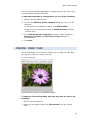
PREVIEW IMAGE FILES
File Preview allows you to view the contents of an image file (jpg, bmp,
gif, png etc.) before you recover the file.
File Preview Dialog Box
Preview files are shown in a separate window.
To open the File Preview dialog box from any view, do one of the
following:
· Double-click an image file.
· Right-click an image file and click File Preview from the context
menu.
43
Hardware Diagnostic File
· Select an image file and click File Preview from the main toolbar.
To recover a file from the File Preview dialog box, do one of the
following:
· Click Recover.
· Right-click anywhere in the preview window and click Recover from
the context menu.
· To add the preview file to Recovery Toolbox, click Add to Recovery
Toolbox. You may recover this file along with all other files in
Recovery Toolbox.
Note: If the preview file is not an image file, it appears in hexadecimal and text
mode.
To open a preview file in Hex Editor, do one of the following:
· Click Open in Hex Editor.
· Right-click anywhere in the preview window and click Open in Hex
Editor from the context menu.
Note: To change File Preview options, open the Preferences dialog box. For
more information, see Application Preferences in Chapter 2, Getting
Started.
HARDWARE DIAGNOSTIC FILE
If you want to contact our technical support staff for help with file
recovery, a file that contains a summary of your local devices is helpful.
Active@ UNDELETE allows you to create a summary listing file in XML
format. This data format is “human-readable” and can help our technical
support staff analyze your computer configuration or point out disk
failures.
To create a hardware diagnostic file:
1. From the File menu, click Save Hardware Info As...
Note: To save time when contacting our technical support staff, we highly
recommend that you provide us with a hardware diagnostic file.
44
Active@ UNDELETE 7.0 User Guide
Overview
HEX EDITOR
OVERVIEW
Hex Editor is advanced tool for viewing and editing sectors of Physical
Disks, Partitions and contents of any file type.
Hex Editor uses a simple, low-level disk viewer which displays information
in binary and text modes at the same time. You can use this view to
analyze the contents of data storage structure elements such as:
· Hard disk drives
· Floppy drives
· Partitions
· Files
· Other objects
To open any of these items in the editor:
1. In the Active@ UNDELETE Recovery Explorer tree pane or file pane
select an item.
2. Do one of the following:
· From the Edit menu, click Open In Hex Editor.
· Right-click the item and click Open In Hex Editor from the context
menu.
Hex Editor shows detailed information about the selected object in the
information panel on the left side of the view. The right panel displays the
binary and text view of the file.
After the Hex Editor view appears, you may browse through the content
of the open item using the scroll bar, keyboard arrows or the mouse
wheel.
Click either the binary area or the text area to focus on it. You may also
use the Tab keyboard key to switch the focus between hexadecimal and
text modes.
45
Hex Editor
OPEN OBJECTS FOR EDITING
You can open a physical disk, a logical drive and partitions or a file from
any of the application views (for example, Recovery Explorer view or
Documents view).
From the Hex Editor view, to open a disk for editing:
1. From the Hex Editor toolbar, click Open Disk. The Open Disk dialog
box appears.
2. Select a physical disk or a logical drive.
3. Click Open. The selected object appears in Hex Editor.
WARNING: As with any advanced tool, use “advanced caution” with Hex Editor.
Changes that you make may affect disk structure integrity. You must be
certain that the changes you make are in line with correct data structures
before you save changes.
SUBJECT NAVIGATION AND INFORMATION
After you have opened an object with Hex Editor, you may navigate by
scrolling block by block, or by “jumping” directly to specific addresses.
You may jump to disk system records, such as the boot sector (primary
and copy) or partition table. In a file’s cluster chain list, you may jump to
the first cluster of a continuous cluster chunk when working with a file.
46
Active@ UNDELETE 7.0 User Guide
Subject Navigation and Information
To open the Navigate menu, do one of the following:
· In the Hex Editor toolbar, open the Navigate drop-down menu.
· Right-click in the editor pane and open the Navigate submenu in the
context menu.
The selections that appear depend on the type of object that you are
editing.
Example Navigate Menu Selections
NAVIGATE A PHYSICAL DISK
To navigate to the disk system records of a physical disk, open the
Navigate menu.
To open the Navigate menu, do one of the following:
· In the Hex Editor toolbar, open the Navigate drop-down menu.
· Right-click in the editor pane and open the Navigate submenu in the
context menu.
Note: To open the disk system record in a template dialog, select menu item
marked with icon and the word Template. For more information about
templates, see Editing using Templates, later in this chapter.
To navigate to a particular area on a physical disk:
1. To open the Go to offset dialog box, do one of the following:
· From the Navigate menu, click Jump To…
· Right-click in the editor pane and choose Navigate > Jump To…
from the context menu.
47
Hex Editor
“Go to Offset Dialog Box for a Physical Disk
2. To jump to an exact sector (address) offset, select Logical offset
and enter the exact sector value in the Sector field.
3. To specify disk geometry, select Disk Geometry and enter the number
of cylinders, heads and sectors in the appropriate fields. To help you
enter these values, the minimum and maximum values appear to the
right of each field.
NAVIGATE A LOGICAL DRIVE
To navigate to disk system records of a logical drive, open the Navigate
menu.
To open the Navigate menu, do one of the following:
· In the Hex Editor Toolbar, open the Navigate drop-down menu.
· Right-click in the editor pane and open the Navigate submenu in the
context menu.
Note: To open the disk system record in a template dialog, select menu item
marked with icon and the word Template. For more information about
templates, see Editing using Templates, later in this chapter.
To navigate to a particular area on a logical drive:
1. To open the Go to offset dialog box, do one of the following:
· From the Navigate menu, click Jump To…
· Right-click in the editor pane and choose Navigate > Jump To…
from the context menu.
48
Active@ UNDELETE 7.0 User Guide
Subject Navigation and Information
“Go to Offset” Dialog Box for a Logical Drive
2. To jump to an exact offset, select Logical Offset and enter the exact
value in sectors or clusters. To help you enter these values, the
minimum and maximum values appear to the right of each field.
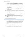
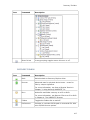
NAVIGATE THE CLUSTER CHAINS OF A FILE
File Cluster Chain
To help navigate through the content of open files, file cluster
information is displayed at the left side of the editor under the
object description. You can select any cluster in this list jump
immediately to that cluster or simply scroll through the list to
view selected cluster content.
To navigate to a particular area of a file:
1. To open the Go to offset dialog box, do one of the following:
· From the Navigate menu, click Jump To…
· Right-click in the editor pane and choose Navigate > Jump To…
from the context menu.
2. To jump to an exact offset, select Logical Offset and enter the exact
value in sectors. To help you enter these values, the minimum and
maximum values appear to the right of the field.
3. To navigate through files cluster chain blocks (continuous file
clusters) click File Cluster Chain.
49
Hex Editor
Example File Cluster Chain List
50
Active@ UNDELETE 7.0 User Guide
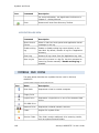
Data Inspector
DATA INSPECTOR
Data Inspector is a small table window that provides the service of
“inspecting” (or interpreting) data currently selected in the edit pane. The
Data Inspector table lets you view the type of data you have selected.
This may help you interpret data as displayed in Disk Hex Editor.
The Data inspector window disappears when you click on another area in
the explorer, and appears again when you return to the Hex Editor.
There are ten types to choose from.
Example Data Inspector Table
To open the Data Inspector:
1. Right-click in the edit panel and choose Data Inspector from the
context menu.
To change the way Data Inspector displays information:
1. Right-click anywhere in the Data Inspector window.
2. To show or hide any of the types displayed in Data Inspector:
· Select Show.
· Clear the check mark next to a type that you want to hide.
· Select a cleared type to show it.
3. To change the way that values are displayed, in the context menu,
choose one of:
· Octal view
· Hexadecimal view
· Decimal view
4. To hide Data Inspector, choose Hide from the context menu.
51
Hex Editor
EDITING WITH HEX EDITOR
Hex Editor allows you to edit the content of a selected part of an opened
object. By default, Hex Editor shows content of an object in Read Only
mode that prevents accidental modifications. In Edit mode, you can
change content of the opened file or disk and all modifications are stored
in memory.
Changes are written to the drive when you click Save.
To toggle between Read Only and Edit modes, do one of the
following:
· From the Hex Editor Toolbar, choose Edit > Allow Edit content.
· Right-click in the edit pane and choose Allow Edit content from the
context menu.
When you copy selected text from the edit pane to the clipboard, you
may store it there in one of three formats:
· Binary – hexadecimal representation of selected data
· Text – text representation of selected data
· Display – formatted hexadecimal and text representation of selected
data (as it appears in the editor)
EDITING USING TEMPLATES
You can edit Disk System Records (MFT, Boot sector etc.) by using
specially designed forms. The system record that appears in the Navigate
menu may be different, depending on the type of object that you have
opened in the Hex Editor.
To open a system record in the template dialog, do one of the
following:
· In the Hex Editor toolbar, choose Navigate > [system record]
(Template).
· Right-click in the editor pane and choose Navigate To > [system
record] (Template) from the context menu.
52
Active@ UNDELETE 7.0 User Guide
Editing with Hex Editor
Example Partition Table Template Dialog Box
To change any value in the template dialog box, select the field and type
a new value.
The pencil icon (
changed.
) beside a field indicates that value has been
53
Hex Editor
To discard all changes and restore all values to fields in the dialog box,
click Reset.
To save all changes made in the dialog box, click Save.
WARNING Saving incorrect values might render the partition useless. You may not
undo changes that you make in this dialog box.
Example Boot Sector Template Dialog Box
The fields that appear may vary, depending on the type of file system
(FAT, FAT32 or NTFS).
You can edit the primary and copy of the boot sector record
simultaneously. To do so, switch back and forth between Boot Sector
Primary and Boot Sector Copy to compare field values. Select Boot Sector
Primary and type a value into a field and then select Boot Sector Copy
and type a value into the same field.
The pencil icon (
changed.
) beside a field indicates that value has been
The caution icon (
) beside a field indicates that the value in the Boot
Sector Primary is different from the same field in Boot Sector Copy.
To discard all changes and restore all values to fields in the dialog box,
click Reset.
To save all changes made in the dialog box, click Save.
WARNING Saving incorrect values might render the boot sector useless. You may
not undo changes that you make in this dialog box.
54
Active@ UNDELETE 7.0 User Guide
Hex Editor Preferences
SAVING CHANGES
Unless stated otherwise, all modifications made in the Hex Editor are
stored in memory.
Changes are written to the drive when you click Save.
HEX EDITOR PREFERENCES
There are several options available in Hex Editor.
To set Hex Editor options:
1. From the Hex Editor toolbar, click Options. The Preferences dialog
box appears.
2. In Editor Window Options:
· To hide the status bar at the bottom of the edit pane, clear the
Show Status pane check box. To show the status bar, select this
check box.
· To hide the Info pane on the left side of the workspace, clear the
Show Info pane check box. To show the Info pane, select this
check box.
· To display text in hexadecimal offset format, select the
Hexadecimal address check box. To display text in decimal
format, clear this check box.
· To change the font size in the edit pane, select a font size from the
Font size drop-down list.
3. In Data Inspector:
· To show a format type, select the check box next to the type name.
To hide a format type, clear the check box next to the type name.
File Cluster Chain
To help navigate through the content of open files, file cluster information
is displayed at the left side of the editor under the object description. You
can select any cluster in this list jump immediately to that cluster or
simply scroll through the list to view selected cluster content.
55
6. KNOWLEDGE BASE
This chapter describes some basic concepts that might help when unerasing data.
HARDWARE AND DISK ORGANIZATION
Here you can get some information about HDDs (Hard Disk Drives) and low-level
disk organization:
· Hard Disk Drive Basics
· Master Boot Record (MBR)
· Partition Table
HARD DISK DRIVE BASICS
Each hard disk consists of platters, with rings on both sides of each platter. These
rings are called tracks. Sections within each track are called sectors. A sector is the
smallest physical storage unit on a disk. A sector is almost always 512 bytes in size.
Hard disk with two platters
The structure of older hard drives (for example, prior to Windows 95) refers to a
cylinder/ head/ sector notation. All current disks use a translation factor to make
their actual hardware layout appear continuous.
TRACKS AND CYLENDERS
On a hard disk, data is stored in thin, concentric bands. A drive head, while in one
position can read or write a circular ring, or band called a track. There can be more
than a thousand tracks on a 3.5-inch hard disk.
Hardware and Disk Organization
Tracks are a logical rather than a physical structure, and are established when the
disk is low-level formatted. Track numbers start at 0, and track 0 is the outermost
track of the disk. The highest numbered track is next to the spindle. If the disk
geometry is being translated, the highest numbered track would typically be 1023.
A hard disk showing track 0, a track in the middle of the disk, and track 1023
A cylinder consists of the set of tracks that are at the same head position on each
disk. In the picture above, cylinder 0 is the four tracks at the outermost edge of the
sides of the platters. If the disk has 1024 cylinders (which would be numbered 01023), cylinder 1023 consists of all of the tracks at the innermost edge of each side.
Most disks used in personal computers today rotate at a constant angular velocity.
The tracks near the outside of the disk are less densely populated with data than the
tracks near the center of the disk. Thus, a fixed amount of data can be read in a
constant period of time, even though the speed of the disk surface is faster on the
tracks located further away from the center of the disk.
Modern disks reserve one side of one platter for track positioning information, which
is written to the disk at the factory during disk assembly. It is not available to the
operating system. The disk controller uses this information to fine tune the head
locations when the heads move to another location on the disk. When a side
contains the track position information, that side cannot be used for data. Thus, a
disk assembly containing two platters has three sides that are available for data.
SECTORS AND CLUSTERS
Each track is divided into sections called sectors. A sector is the smallest physical
storage unit on the disk.
Each track has the same number of sectors, which means that the sectors are
packed much closer together on tracks near the center of the disk.
The picture below shows sectors on a track. You can see that sectors closer to the
spindle are closer together than those on the outside edge of the disk. The disk
controller uses the sector identification information stored in the area immediately
before the data in the sector to determine where the sector itself begins.
57
Hex Editor
Hard disk showing sectors on a track
As a file is written to the disk, the file system allocates the appropriate number of
clusters to store the file's data. For example, if each cluster is 512 bytes and the file
is 800 bytes, two clusters are allocated for the file. Later, if you update the file to,
for example, twice its size (1600 bytes), another two clusters are allocated.
If contiguous clusters (clusters that are next to each other on the disk) are not
available, the data are written elsewhere on the disk and the file is considered to be
fragmented. Fragmentation is a problem when the file system must search several
different locations to find all the pieces of the file you want to read. The search
causes a delay before the file is retrieved. A larger cluster size reduces the potential
for fragmentation, but increases the likelihood that clusters will have unused space.
Using clusters larger than one sector reduces fragmentation, and reduces the
amount of disk space needed to store the information about the used and unused
areas on the disk.
MBR (MASTER BOOT RECORD)
The Master Boot Record, created when you create the first partition on the hard
disk, is probably the most important data structure on the disk. It is the first sector
on every disk. The location is always track (cylinder) 0, side (head) 0, and sector 1.
The Master Boot Record contains the Partition Table for the disk and a small amount
of executable code. On x86-based computers, the executable code examines the
Partition Table, and identifies the system partition. The Master Boot Record then
finds the system partition's starting location on the disk, and loads a copy of its
Partition Boot Sector into memory. The Master Boot Record then transfers execution
to executable code in the Partition Boot Sector.
Note Although there is a Master Boot Record on every hard disk, the executable code in
the sector is used only if the disk is connected to an x86-based computer and the
disk contains the system partition.
Figure below shows a hex dump of the sector containing the Master Boot Record.
The figure shows the sector in two parts. The first part is the Master Boot Record,
which occupies the first 446 bytes of the sector. The disk signature (FD 4E F2 14) is
at the end of the Master Boot Record code. The second part is the Partition Table.
Physical Sector: Cyl 0, Side 0, Sector 1
58
Active@ UNDELETE 7.0 User Guide
Hardware and Disk Organization
00000000:
00000010:
00000020:
00000030:
00000040:
00000050:
00000060:
00000070:
00000080:
00000090:
000000A0:
000000B0:
000000C0:
000000D0:
000000E0:
000000F0:
00000100:
00000110:
00000120:
00000130:
00000140:
00000150:
00000160:
00000170:
00000180:
00000190:
000001A0:
000001B0:
00
BF
B3
CB
CB
56
BB
4F
55
69
6C
20
6D
69
00
00
00
00
00
00
00
00
00
00
00
00
00
00
33
00
04
75
74
BB
00
75
AA
64
65
6F
00
6E
00
00
00
00
00
00
00
00
00
00
00
00
00
00
C0
06
80
EF
1A
07
7C
ED
75
20
00
70
4D
67
00
00
00
00
00
00
00
00
00
00
00
00
00
00
8E
B9
3C
CD
80
00
B8
BE
C7
70
45
65
69
20
00
00
00
00
00
00
00
00
00
00
00
00
00
00
D0
00
80
18
3C
B4
01
A3
8B
61
72
72
73
73
00
00
00
00
00
00
00
00
00
00
00
00
00
00
BC
01
74
8B
00
0E
02
06
F5
72
72
61
73
79
00
00
00
00
00
00
00
00
00
00
00
00
00
00
00
F2
0E
14
74
CD
57
EB
EA
74
6F
74
69
73
00
00
00
00
00
00
00
00
00
00
00
00
00
00
7C
A5
80
8B
F4
10
CD
D3
00
69
72
69
6E
74
00
00
00
00
00
00
00
00
00
00
00
00
00
00
-
8B
EA
3C
4C
BE
5E
13
BE
7C
74
20
6E
67
65
00
00
00
00
00
00
00
00
00
00
00
00
00
FD
F4
1D
00
02
8B
EB
5F
C2
00
69
6C
67
20
6D
00
00
00
00
00
00
00
00
00
00
00
00
00
4E
50
06
75
8B
06
F0
73
06
00
6F
6F
20
6F
00
00
00
00
00
00
00
00
00
00
00
00
00
00
F2
07
00
1C
EE
AC
EB
0C
BF
49
6E
61
73
70
00
00
00
00
00
00
00
00
00
00
00
00
00
00
14
50
00
83
83
3C
FE
33
FE
6E
20
64
79
65
80
00
00
00
00
00
00
00
00
00
00
00
00
00
00
1F
BE
C6
C6
00
BF
C0
7D
76
74
69
73
72
45
00
00
00
00
00
00
00
00
00
00
00
00
00
00
000001C0:
000001D0:
000001E0:
000001F0:
01
41
C1
C1
00
97
2D
93
06
07
05
01
0F
0F
0F
0F
7F
FF
FF
FF
96
2C
92
A6
3F
90
30
D0
00
42
81
12
-
00
06
0C
0E
00
00
00
00
51
A0
A0
C0
42
3E
91
4E
06
06
01
00
00
00
00
00
FB
BE
10
10
74
05
CD
81
61
61
6E
74
61
14
00
00
00
00
00
00
00
00
00
00
00
00
00
FC
07
FE
FE
0B
00
13
3D
6C
62
67
65
74
15
00
00
00
00
00
00
00
00
00
00
00
00
00
.3.....|..P.P..
................
...<.t..<.u.....
.u......L.......
.t..<.t.....<.t.
V.......^.......
..|...W.._s.3...
Ou...........}.=
U.u.....|..Inval
id partition tab
le.Error loading
operating syste
m.Missing operat
ing system...E..
................
................
................
................
................
................
................
................
................
................
................
................
................
.........N......
80
00
00
00
55
01
00
00
00
AA
..
....•.?...QB....
A....,.B...>....
.-....0.........
...........N..U.
IMPORTANT Viruses Can Infect the Master Boot Record.
Many destructive viruses damage the Master Boot Record and make it impossible to
start the computer from the hard disk. Because the code in the Master Boot Record
executes before any operating system is started, no operating system can detect or
recover from corruption of the Master Boot Record. You can use, for example, the
DiskProbe program on Windows NT Workstation Resource Kit CD to display the
Master Boot Record, and compare it to the Master Boot Record shown above. There
are also utilities on the Microsoft Windows Resource Kits that enable you to save and
restore the Master Boot Record.
PARTITION TABLE
The Master Boot Record contains the Partition Table for the disk and a small amount
of executable code for the boot start. The location is always the first sector on the
disk.
59
Understanding the File System: FAT
The first 446 (0x1BE) bytes are MBR itself, the next 64 bytes are the Partition Table,
and the last two bytes in the sector are a signature word for the sector and are
always 0x55AA.
UNDERSTANDING THE FILE SYSTEM: FAT
The FAT (File Allocation Table) file system is a simple file system originally designed
for small disks and simple folder structures. The FAT file system is named for its
method of organization, the file allocation table, which resides at the beginning of
the volume. To protect the volume, two copies of the table are kept, in case one
becomes damaged. In addition, the file allocation tables and the root folder must be
stored in a fixed location so that the files needed to start the system can be
correctly located.
A volume formatted with the FAT file system is allocated in clusters. The default
cluster size is determined by the size of the volume. For the FAT file system, the
cluster number must fit in 16 bits and must be a power of two.
FAT PARTITION BOOT SECTOR
The Partition Boot Sector contains information that the file system uses to access
the volume. On x86-based computers, the Master Boot Record use the Partition Boot
Sector on the system partition to load the operating system kernel files.
The table below describes the fields in the Partition Boot Sector for a volume
formatted with the FAT file system.
60
Byte Offset
(in hex)
Field Length
Sample Value
Description
00
3 bytes
EB 3C 90
Jump instruction.
03
8 bytes
MSDOS5.0
OEM Name in text
0B
25 bytes
BIOS Parameter Block
24
26 bytes
Extended BIOS Parameter
Block
3E
448 bytes
Bootstrap code
1FE
2 bytes
0x55AA
End of sector marker
Active@ UNDELETE 7.0 User Guide
FAT Partition Boot Sector
The table below describes BIOS Parameter Block and Extended BIOS Parameter
Block Fields
Byte Offset
(in hex)
Field Length
Sample
Value
Description
0x0B
WORD
0x0002
Bytes per Sector. The size of a
hardware sector. For most disks
in use in the United States, the
value of this field is 512.
0x0D
BYTE
0x08
Sectors Per Cluster. The number
of sectors in a cluster. The
default cluster size for a volume
depends on the volume size and
the file system.
0x0E
WORD
0x0100
Reserved Sectors. The number of
sectors from the Partition Boot
Sector to the start of the first file
allocation table, including the
Partition Boot Sector. The
minimum value is 1. If the value
is greater than 1, it means that
the bootstrap code is too long to
fit completely in the Partition
Boot Sector.
0x10
BYTE
0x02
Number of file allocation tables
(FATs). The number of copies of
the file allocation table on the
volume. Typically, the value of
this field is 2.
0x11
WORD
0x0002
Root Entries. The total number of
file name entries that can be
stored in the root folder of the
volume. One entry is always
used as a Volume Label. Files
with long filenames use up
multiple entries per file.
Therefore, the largest number of
files in the root folder is typically
511, but you will run out of
entries sooner if you use long
filenames.
0x13
WORD
0x0000
Small Sectors. The number of
sectors on the volume if the
number fits in 16 bits (65535).
For volumes larger than 65536
sectors, this field has a value of
0 and the Large Sectors field is
61
Understanding the File System: FAT
Byte Offset
(in hex)
Field Length
Sample
Value
Description
used instead.
62
0x15
BYTE
0xF8
Media Type. Provides information
about the media being used. A
value of 0xF8 indicates a hard
disk.
0x16
WORD
0xC900
Sectors per file allocation table
(FAT). Number of sectors
occupied by each of the file
allocation tables on the volume.
By using this information,
together with the Number of
FATs and Reserved Sectors, you
can compute where the root
folder begins. By using the
number of entries in the root
folder, you can also compute
where the user data area of the
volume begins.
0x18
WORD
0x3F00
Sectors per Track. The apparent
disk geometry in use when the
disk was low-level formatted.
0x1A
WORD
0x1000
Number of Heads. The apparent
disk geometry in use when the
disk was low-level formatted.
0x1C
DWORD
3F 00 00
00
Hidden Sectors. Same as the
Relative Sector field in the
Partition Table.
0x20
DWORD
51 42 06
00
Large Sectors. If the Small
Sectors field is zero, this field
contains the total number of
sectors in the volume. If Small
Sectors is nonzero, this field
contains zero.
0x24
BYTE
0x80
Physical Disk Number. This is
related to the BIOS physical disk
number. Floppy drives are
numbered starting with 0x00 for
the A disk. Physical hard disks
are numbered starting with
0x80. The value is typically 0x80
for hard disks, regardless of how
many physical disk drives exist,
because the value is only
relevant if the device is the
startup disk.
0x25
BYTE
0x00
Current Head. Not used by the
Active@ UNDELETE 7.0 User Guide
File Allocation System
Byte Offset
(in hex)
Field Length
Sample
Value
Description
FAT file system.
0x26
BYTE
0x29
Signature. Must be either 0x28
or 0x29 in order to be recognized
by Windows NT.
0x27
4 bytes
CE 13 46
30
Volume Serial Number. A unique
number that is created when you
format the volume.
0x2B
11 bytes
NO NAME
Volume Label. This field was
used to store the volume label,
but the volume label is now
stored as special file in the root
directory.
0x36
8 bytes
FAT16 System ID. Either FAT12
or FAT16, depending on the
format of the disk.
For more detailed information see resource kits on Microsoft's web site
http://www.microsoft.com/windows/reskits/webresources/default.asp or Microsoft
Developers Network (MSDN) http://msdn.microsoft.com
FILE ALLOCATION SYSTEM
The FAT file allocation system is named for its method of organization, the file
allocation table, which resides at the beginning of the volume. To protect the
volume, two copies of the table are kept, in case one becomes damaged. In
addition, the file allocation tables must be stored in a fixed location so that the files
needed to start the system can be correctly located.
The file allocation table contains the following types of information about each
cluster on the volume (see example below for FAT16):
Three files
This picture shows three files. The file File1.txt is a file that is large enough to use
three clusters. The second file, File2.txt, is a fragmented file that also requires three
clusters. A small file, File3.txt, fits completely in one cluster. In each case, the folder
structure points to the first cluster of the file.
63
Understanding the File System: FAT
For more detailed information see resource kits on Microsoft's web site
http://www.microsoft.com/windows/reskits/webresources/default.asp or Microsoft
Developers Network (MSDN) http://msdn.microsoft.com
FAT ROOT FOLDER
The root folder contains an entry for each file and folder on the root. The only
difference between the root folder and other folders is that the root folder is on a
specified location on the disk and has a fixed size (512 entries for a hard disk,
number of entries on a floppy disk depends on the size of the disk). See Folder
Structure topic for details about folder organization.
For more detailed information see resource kits on Microsoft's web site
http://www.microsoft.com/windows/reskits/webresources/default.asp or Microsoft
Developers Network (MSDN) http://msdn.microsoft.com
FAT FOLDER STRUCTURE
Folders have set of 32-byte Folder Entries for each file and subfolder contained in
the folder (see example figure below).
Long File Name Folder Entry Example
The Folder Entry includes the following information:
· Name (eight-plus-three characters)
· Attribute byte (8 bits worth of information, described later in this section)
· Create time (24 bits)
· Create date (16 bits)
· Last access date (16 bits)
64
Active@ UNDELETE 7.0 User Guide
FAT32 Features
· Last modified time (16 bits)
· Last modified date (16 bits.)
· Starting cluster number in the file allocation table (16 bits)
· File size (32 bits)
There is no organization to the FAT folder structure, and files are given the first
available location on the volume. The starting cluster number is the address of the
first cluster used by the file. Each cluster contains a pointer to the next cluster in the
file, or an indication (0xFFFF) that this cluster is the end of the file.
See File Allocation System for details.
The information in the folder is used by all operating systems that support the FAT
file system. In addition, Windows NT can store additional time stamps in a FAT
folder entry. These time stamps show when the file was created or last accessed and
are used principally by POSIX applications.
Because all entries in a folder are the same size, the attribute byte for each entry in
a folder describes what kind of entry it is. One bit indicates that the entry is for a
subfolder, while another bit marks the entry as a volume label.
Normally, only the operating system controls the settings of these bits. A FAT file
has four attributes bits that can be turned on or off by the user — archive file,
system file, hidden file, and read-only file.
FILENAMES ON FAT VOLUMES
Beginning with Windows NT 3.5, files created or renamed on FAT volumes use the
attribute bits to support long filenames in a way that does not interfere with how
MS-DOS or OS/2 accesses the volume. Whenever a user creates a file with a long
filename, Windows creates an eight-plus-three name for the file. In addition to this
conventional entry, Windows creates one or more secondary folder entries for the
file, one for each 13 characters in the long filename. Each of these secondary folder
entries stores a corresponding part of the long filename in Unicode. Windows sets
the volume, read-only, system, and hidden file attribute bits of the secondary folder
entry to mark it as part of a long filename. MS-DOS and OS/2 generally ignore
folder entries with all four of these attribute bits set, so these entries are effectively
invisible to these operating systems. Instead, MS-DOS and OS/2 access the file by
using the conventional eight-plus-three filename contained in the folder entry for the
file.
The Long File Name Example above shows all of the folder entries for the file
Thequi~1.fox, which has a long name of The quick brown.fox. The long name is in
Unicode, so each character in the name uses two bytes in the folder entry. The
attribute field for the long name entries has the value 0x0F. The attribute field for
the short name is 0x20.
FAT32 FEATURES
The following topics describe the FAT32 file system.
· File System Specifications
· Boot Sector and Bootstrap Modifications
65
Understanding the File System: FAT
· FAT Mirroring
· Partition Types
File System Specifications
FAT32 is a derivative of the File Allocation Table (FAT) file system that supports
drives with over 2GB of storage. Because FAT32 drives can contain more than
65,526 clusters, smaller clusters are used than on large FAT16 drives. This method
results in more efficient space allocation on the FAT32 drive.
The largest possible file for a FAT32 drive is 4GB minus 2 bytes.
The FAT32 file system includes four bytes per cluster within the file allocation table.
Note that the high 4 bits of the 32-bit values in the FAT32 file allocation table are
reserved and are not part of the cluster number.
Modifications to Boot Sector
66
Modifications
Description
Reserved Sectors
FAT32 drives contain more reserved sectors than FAT16
or FAT12 drives. The number of reserved sectors is
usually 32, but can vary.
Boot Sector
Modifications
Because a FAT32 BIOS Parameter Block (BPB),
represented by the BPB structure, is larger than a
standard BPB, the boot record on FAT32 drives is
greater than 1 sector. In addition, there is a sector in
the reserved area on FAT32 drives that contains values
for the count of free clusters and the cluster number of
the most recently allocated cluster. These values are
members of the BIGFATBOOTFSINFO structure which is
contained within this sector. These additional fields
allow the system to initialize the values without having
to read the entire file allocation table.
Root Directory
The root directory on a FAT32 drive is not stored in a
fixed location as it is on FAT16 and FAT12 drives. On
FAT32 drives, the root directory is an ordinary cluster
chain. The A_BF_BPB_RootDirStrtClus member in the
BPB structure contains the number of the first cluster in
the root directory. This allows the root directory to grow
as needed. In addition, the BPB_RootEntries member of
BPB is ignored on a FAT32 drive.
Sectors Per FAT
The A_BF_BPB_SectorsPerFAT member of BPB is always
zero on a FAT32 drive. Additionally, the
A_BF_BPB_BigSectorsPerFat and
A_BF_BPB_BigSectorsPerFatHi members of the updated
BPB provide equivalent information for FAT32 media.
Active@ UNDELETE 7.0 User Guide
FAT32 Features
BPB (FAT32)
The BPB for FAT32 drives is an extended version of the FAT16/FAT12 BPB. It
contains identical information to a standard BPB, but also includes several extra
fields for FAT32 specific information.
This structure is implemented in Windows OEM Service Release 2 and later.
A_BF_BPB STRUC
A_BF_BPB_BytesPerSector DW ?
A_BF_BPB_SectorsPerCluster DB ?
A_BF_BPB_ReservedSectors DW ?
A_BF_BPB_NumberOfFATs DB ?
A_BF_BPB_RootEntries DW ?
A_BF_BPB_TotalSectors DW ?
A_BF_BPB_MediaDescriptor DB ?
A_BF_BPB_SectorsPerFAT DW ?
A_BF_BPB_SectorsPerTrack DW ?
A_BF_BPB_Heads DW ?
A_BF_BPB_HiddenSectors DW ?
A_BF_BPB_HiddenSectorsHigh DW ?
A_BF_BPB_BigTotalSectors DW ?
A_BF_BPB_BigTotalSectorsHigh DW ?
A_BF_BPB_BigSectorsPerFat DW ?
A_BF_BPB_BigSectorsPerFatHi DW ?
A_BF_BPB_ExtFlags DW ?
A_BF_BPB_FS_Version DW ?
A_BF_BPB_RootDirStrtClus DW ?
A_BF_BPB_RootDirStrtClusHi DW ?
A_BF_BPB_FSInfoSec DW ?
A_BF_BPB_BkUpBootSec DW ?
A_BF_BPB_Reserved DW 6 DUP (?)
A_BF_BPB ENDS
BPB Members
Member Name
Description
A_BF_BPB_BytesPerSector
The number of bytes per sector.
A_BF_BPB_SectorsPerCluster
The number of sectors per cluster.
A_BF_BPB_ReservedSectors
The number of reserved sectors, beginning
with sector 0.
A_BF_BPB_NumberOfFATs
The number of File Allocation Tables.
A_BF_BPB_RootEntries
This member is ignored on FAT32 drives.
A_BF_BPB_TotalSectors
The size of the partition, in sectors.
67
Understanding the File System: FAT
Member Name
Description
A_BF_BPB_MediaDescriptor
The media descriptor. Values in this
member are identical to standard BPB.
A_BF_BPB_SectorsPerFAT
The number of sectors per FAT.
Note This member will always be zero in a FAT32 BPB. Use the values from
A_BF_BPB_BigSectorsPerFat and A_BF_BPB_BigSectorsPerFatHi for FAT32
media.
A_BF_BPB_SectorsPerTrack
The number of sectors per track.
A_BF_BPB_Heads
The number of read/write heads on the
drive.
A_BF_BPB_HiddenSectors
The number of hidden sectors on the drive.
A_BF_BPB_HiddenSectorsHigh
The high word of the hidden sectors value.
A_BF_BPB_BigTotalSectors
The total number of sectors on the FAT32
drive.
A_BF_BPB_BigTotalSectorsHigh
The high word of the FAT32 total sectors
value.
A_BF_BPB_BigSectorsPerFat
The number of sectors per FAT on the
FAT32 drive.
A_BF_BPB_BigSectorsPerFatHi
The high word of the FAT32 sectors per FAT
value.
A_BF_BPBExtFlags
Flags describing the drive. Bit 8 of this
value indicates whether or not information
written to the active FAT will be written to
all copies of the FAT. The low 4 bits of this
value contain the 0-based FAT number of
the Active FAT, but are only meaningful if
bit 8 is set. This member can contain a
combination of the following values.
Value
Description
BGBPB_F_ActiveFATMsk
Mask for low four bits. (000Fh)
BGBPB_F_NoFATMirror
Mask indicating FAT (0080h) mirroring
state. If set, FAT mirroring is disabled. If
clear, FAT mirroring is enabled.
Bits 4-6 and 8-15 are reserved.
68
A_BF_BPB_FS_Version
The file system version number of the
FAT32 drive. The high byte represents the
major version, and the low byte represents
the minor version.
A_BF_BPB_RootDirStrtClus
The cluster number of the first cluster in the
FAT32 drive's root directory.
A_BF_BPB_RootDirStrtClusHi
The high word of the FAT32 starting cluster
number. A_BF_BPB_FSInfoSec The sector
Active@ UNDELETE 7.0 User Guide
FAT32 Features
Member Name
Description
number of the file system information
sector. The file system info sector contains
a BIGFATBOOTFSINFO structure. This
member is set to 0FFFFh if there is no
FSINFO sector. Otherwise, this value must
be non-zero and less than the reserved
sector count.
A_BF_BPB_BkUpBootSec
The sector number of the backup boot
sector. This member is set to 0FFFFh if
there is no backup boot sector. Otherwise,
this value must be non-zero and less than
the reserved sector count.
A_BF_BPB_Reserved
Reserved member.
BIGFATBOOTFSINFO (FAT32)
Contains information about the file system on a FAT32 volume. This structure is
implemented in Windows OEM Service Release 2 and later.
BIGFATBOOTFSINFO STRUC
bfFSInf_Sig DD ?
bfFSInf_free_clus_cnt DD ?
bfFSInf_next_free_clus DD ?
bfFSInf_resvd DD 3 DUP (?)
BIGFATBOOTFSINFO ENDS
BIGFATBOOTFSINFO Members
Member Name
Description
bfFSInf_Sig
The signature of the file system information
sector. The value in this member is
FSINFOSIG (0x61417272L).
bfFSInf_free_clus_cnt
The count of free clusters on the drive. Set
to -1 when the count is unknown.
bfFSInf_next_free_clus
The cluster number of the cluster that was
most recently allocated.
bfFSInf_resvd
Reserved member.
FAT MIRRORING
On all FAT drives, there may be multiple copies of the FAT. If an error occurs
reading the primary copy, the file system will attempt to read from the backup
copies. On FAT16 and FAT12 drives, the first FAT is always the primary copy and
69
Understanding the File System: FAT
any modifications will automatically be written to all copies. However, on FAT32
drives, FAT mirroring can be disabled and a FAT other than the first one can be the
primary (or “active”) copy of the FAT.
Mirroring is enabled by clearing bit 0x0080 in the extdpb_flags member of a FAT32
Drive Parameter Block (DPB) structure.
Mirroring
Description
When Enabled
(bit 0x0080
clear)
With mirroring enabled, whenever a FAT sector is written, it
will also be written to every other FAT. Also, a mirrored FAT
sector can be read from any FAT. A FAT32 drive with
multiple FATs will behave the same as FAT16 and FAT12
drives with multiple FATs. That is, the multiple FATs are
backups of each other.
When Disabled
(bit 0x0080
set)
With mirroring disabled, only one of the FATs is active. The
active FAT is the one specified by bits 0 through 3 of the
extdpb_flags member of DPB. The other FATs are ignored.
Disabling mirroring allows better handling of a drive with a
bad sector in one of the FATs. If a bad sector exists, access
to the damaged FAT can be completely disabled. Then, a
new FAT can be built in one of the inactive FATs and then
made accessible by changing the active FAT value in
extdpb_flags.
DRIVE PARAMETER BLOCK (FAT32)
The DPB was extended to include FAT32 information. Changes are effective for
Windows 95 OEM Service Release 2 and later.
DPB STRUC
dpb_drive DB ?
dpb_unit DB ?
dpb_sector_size DW ?
dpb_cluster_mask DB ?
dpb_cluster_shift DB ?
dpb_first_fat DW ?
dpb_fat_count DB ?
dpb_root_entries DW ?
dpb_first_sector DW ?
dpb_max_cluster DW ?
dpb_fat_size DW ?
dpb_dir_sector DW ?
dpb_reserved2 DD ?
dpb_media DB ?
ifdef NOTFAT32
dpb_first_access DB ?
else
70
Active@ UNDELETE 7.0 User Guide
FAT32 Features
dpb_reserved DB ?
endif
dpb_reserved3 DD ?
dpb_next_free DW ?
dpb_free_cnt DW ?
ifndef NOTFAT32
extdpb_free_cnt_hi DW ?
extdpb_flags DW ?
extdpb_FSInfoSec DW ?
extdpb_BkUpBootSec DW ?
extdpb_first_sector DD ?
extdpb_max_cluster DD ?
extdpb_fat_size DD ?
extdpb_root_clus DD ?
extdpb_next_free DD ?
endif
DPB ENDS
DBP Members
Member Name
Description
dpb_drive
The drive number (0 = A, 1 = B, and so on).
dpb_unit
Specifies the unit number. The device driver uses
the unit number to distinguish the specified drive
from the other drives it supports.
dpb_sector_size
The size of each sector, in bytes.
dpb_cluster_mask The number of sectors per
cluster minus 1.
dpb_cluster_shift
The number of sectors per cluster, expressed as a
power of 2.
dpb_first_fat
The sector number of the first sector containing
the file allocation table (FAT).
dpb_fat_count
The number of FATs on the drive.
dpb_root_entries
The number of entries in the root directory.
dpb_first_sector
The sector number of the first sector in the first
cluster.
dpb_max_cluster
The number of clusters on the drive plus 1. This
member is undefined for FAT32 drives.
dpb_fat_size
The number of sectors occupied by each FAT. The
value of zero indicates a FAT32 drive. Use the
value in extdpb_fat_size instead.
dpb_dir_sector
The sector number of the first sector containing
the root directory. This member is undefined for
71
Understanding the File System: FAT
Member Name
Description
FAT32 drives.
dpb_reserved2
Reserved member. Do not use.
dpb_media
Specifies the media descriptor for the medium in
the specified drive.
reserved
Reserved member. Do not use.
dpb_first_access
Indicates whether the medium in the drive has
been accessed. This member is initialized to -1 to
force a media check the first time this DPB is used.
dpb_reserved3
Reserved member. Do not use.
dpb_next_free
The cluster number of the most recently allocated
cluster.
dpb_free_cnt
The number of free clusters on the medium. This
member is 0FFFFh if the number is unknown.
extdpb_free_cnt_hi
The high word of free count.
extdpb_flags
Flags describing the drive. The low 4 bits of this
value contain the 0-based FAT number of the
Active FAT. This member can contain a
combination of the following values.
Value
Description
BGBPB_F_ActiveFATMsk
Mask for low four bits.
(000Fh)
Do not mirror active FAT to inactive FATs.
BGBPB_F_NoFATMirror
Bits 4-6 and 8-15 are reserved.
(0080h)
72
extdpb_FSInfoSec
The sector number of the file system information
sector. This member is set to 0FFFFh if there is no
FSINFO sector. Otherwise, this value must be nonzero and less than the reserved sector count.
extdpb_BkUpBootSec
The sector number of the backup boot sector. This
member is set to 0FFFFh if there is no backup boot
sector. Otherwise, this value must be non-zero and
less than the reserved sector count.
extdpb_first_sector
The first sector of the first cluster.
extdpb_max_cluster
The number of clusters on the drive plus 1.
extdpb_fat_size
The number of sectors occupied by the FAT.
extdpb_root_clus
The cluster number of the first cluster in the root
directory.
extdpb_next_free
The number of the cluster that was most recently
allocated.
Active@ UNDELETE 7.0 User Guide
FAT32 Features
FAT32 PARTITION TYPES
The following table displays all valid partition types and their corresponding
values for use in the Part_FileSystem member of the s_partition structure.
Value
Description
PART_UNKNOWN (00h)
Unknown
PART_DOS2_FAT (01h)
12-bit FAT
PART_DOS3_FAT (04h)
16-bit FAT. Partitions smaller than 32MB.
PART_EXTENDED (05h)
Extended MS-DOS Partition
PART_DOS4_FAT (06h)
16-bit FAT. Partitions larger than or equal to
32MB.
PART_DOS32 (0Bh) 32bit FAT
Partitions up to 2047GB.
PART_DOS32X (0Ch)
Same as PART_DOS32 (0Bh), but uses Logical
Block Address Int 13h extensions.
PART_DOSX13 (0Eh)
Same as PART_DOS4_FAT (06h), but uses Logical
Block Address Int 13h extensions.
PART_DOSX13X (0Fh)
Same as PART_EXTENDED (05h), but uses Logical
Block Address Int 13h extensions.
S_PARTITION (FAT32)
Note Values for head and track are 0-based. Sector values are 1-based. This structure is
implemented in Windows OEM Service Release 2 and later.
s_partition STRUC
Part_BootInd DB ?
Part_FirstHead DB ?
Part_FirstSector DB ?
Part_FirstTrack DB ?
Part_FileSystem DB ?
Part_LastHead DB ?
Part_LastSector DB ?
Part_LastTrack DB ?
Part_StartSector DD ?
Part_NumSectors DD ?
s_partition ENDS
73
Understanding the File System: FAT
s_partition Members
Member Name
Description
Part_BootInd
Specifies whether the partition is bootable or not.
This value could be set to PART_BOOTABLE (80h),
or PART_NON_BOOTABLE(00h). The first partition
designated as PART_BOOTABLE is the boot
partition. All others are not. Setting multiple
partitions to PART_BOOTABLE will result in boot
errors.
Part_FirstHead
The first head of this partition. This is a 0-based
number representing the offset from the beginning
of the disk. The partition includes this head.
Part_FirstSector
The first sector of this partition. This is a 1-based,
6-bit number representing the offset from the
beginning of the disk. The partition includes this
sector. Bits 0 through 5 specify the 6-bit value;
bits 6 and 7 are used with the Part_FirstTrack
member.
Part_FirstTrack
The first track of this partition. This is an inclusive
0-based, 10-bit number that represents the offset
from the beginning of the disk. The high 2 bits of
this value are specified by bits 6 and 7 of the
Part_FirstSector member.
PartFileSystem
Specifies the file system for the partition. The
following are acceptable values:
Value
Description
PART_UNKNOWN(00h)
Unknown.
PART_DOS2_FAT(01h)
12-bit FAT.
PART_DOS3_FAT(04h)
16-bit FAT. Partition smaller than 32MB.
PART_EXTENDED(05h)
Extended MS-DOS Partition.
PART_DOS4_FAT(06h)
16-bit FAT. Partition larger than or equal to 32MB.
PART_DOS32(0Bh)
32-bit FAT. Partition up to 2047GB.
PART_DOS32X(0Ch)
Same as PART_DOS32(0Bh), but uses Logical
Block Address Int 13h extensions.
PART_DOSX13(0Eh)
PART_DOSX13X(0Fh)
74
Same as PART_DOS4_FAT(06h), but uses Logical
Block Address Int 13h extensions.
Same as PART_EXTENDED(05h), but uses Logical
Block Address Int 13h extensions.
Part_LastHead
The last head of the partition. This is a 0-based
number that represents the offset from the
beginning of the disk. The partition includes the
head specified by this member.
Part_LastSector
The last sector of this partition. This is a 1-based,
Active@ UNDELETE 7.0 User Guide
FAT32 Features
Member Name
Description
6-bit number representing offset from the
beginning of the disk. The partition includes the
sector specified by this member. Bits 0 through 5
specify the 6-bit value; bits 6 and 7 are used with
the Part_LastTrack member.
Part_LastTrack
The last track of this partition. This is a 0-based,
10-bit number that represents offset from the
beginning of the disk. The partition includes this
track. The high 2 bits of this value are specified by
bits 6 and 7 of the Part_LastSector member.
Part_StartSector
Specifies the 1-based number of the first sector on
the disk. This value may not be accurate for
extended partitions. Use the Part_FirstSector value
for extended partitions.
Part_NumSectors
The 1-based number of sectors in the partition.
UNDERSTANDING THE FILE SYSTEM: NTFS
The Windows NT file system (NTFS) provides a combination of performance,
reliability, and compatibility not found in the FAT file system. It is designed to
quickly perform standard file operations such as read, write, and search — and even
advanced operations such as file-system recovery — on very large hard disks.
Formatting a volume with the NTFS file system results in the creation of several
system files and the Master File Table (MFT), which contains information about all
the files and folders on the NTFS volume.
The first information on an NTFS volume is the Partition Boot Sector, which starts at
sector 0 and can be up to 16 sectors long. The first file on an NTFS volume is the
Master File Table (MFT).
The following picture illustrates the layout of an NTFS volume when formatting has
finished.
Formatted NTFS Volume
The NTFS file system includes security features required for file servers and highend personal computers in a corporate environment. The NTFS file system also
supports data access control and ownership privileges that are important for the
integrity of critical data. While folders shared on a Windows NT computer are
assigned particular permissions, NTFS files and folders can have permissions
assigned whether they are shared or not. NTFS is the only file system on Windows
NT that allows you to assign permissions to individual files.
The NTFS file system has a simple, yet very powerful design. Basically, everything
on the volume is a file and everything in a file is an attribute, from the data
75
Understanding The File System: NTFS
attribute, to the security attribute, to the file name attribute. Every sector on an
NTFS volume that is allocated belongs to some file. Even the file system metadata
(information that describes the file system itself) is part of a file.
For more detailed information see resource kits on Microsoft's web site
http://www.microsoft.com/windows/reskits/webresources/default.asp or Microsoft
Developers Network (MSDN) http://msdn.microsoft.com.
This chapter covers information about NTFS. Topics covered are listed below:
• NTFS Partition Boot Sector
• NTFS Master File Table (MFT)
• NTFS File Types
• NTFS Data Integrity and Recoverability
NTFS PARTITION BOOT SECTOR
The table below describes the boot sector of a volume formatted with NTFS. When
you format an NTFS volume, the format program allocates the first 16 sectors for
the boot sector and the bootstrap code.
NTFS Boot Sector
Byte Offset
Field Length
Field Name
0x00
3 bytes
Jump Instruction
0x03
LONGLONG
OEM ID
0x0B
25 bytes
BPB
0x24
48 bytes
Extended BPB
0x54
426 bytes
Bootstrap Code
0x01FE
WORD
End of Sector Marker
On NTFS volumes, the data fields that follow the BPB form an extended BPB. The
data in these fields enables Ntldr (NT loader program) to find the master file table
(MFT) during startup. On NTFS volumes, the MFT is not located in a predefined
sector, as on FAT16 and FAT32 volumes. For this reason, the MFT can be moved if
there is a bad sector in its normal location. However, if the data is corrupted, the
MFT cannot be located, and Windows NT/2000 assumes that the volume has not
been formatted.
The following example illustrates the boot sector of an NTFS volume formatted while
running Windows 2000. The printout is formatted in three sections:
· Bytes 0x00– 0x0A are the jump instruction and the OEM ID (shown in bold print).
· Bytes 0x0B–0x53 are the BPB and the extended BPB.
· The remaining code is the bootstrap code and the end of sector marker (shown in
bold print).
76
Active@ UNDELETE 7.0 User Guide
NTFS Partition Boot Sector
Physical Sector: Cyl 0, Side 1, Sector 1
00000000: EB 52 90 4E 54 46 53 20 - 20 20 20 00 02
08 00 00 .R.NTFS ........ 00000010: 00 00 00 00 00
F8 00 00 - 3F 00 FF 00 3F 00 00 00 ........?...?...
00000020: 00 00 00 00 80 00 80 00 - 4A F5 7F 00 00
00 00 00 ........J....... 00000030: 04 00 00 00 00
00 00 00 - 54 FF 07 00 00 00 00 00 ........T.......
00000040: F6 00 00 00 01 00 00 00 - 14 A5 1B 74 C9
1B 74 1C ...........t..t. 00000050: 00 00 00 00 FA
33 C0 8E - D0 BC 00 7C FB B8 C0 07 .....3.....|....
00000060: 8E D8 E8 16 00 B8 00 0D - 8E C0 33 DB C6
06 0E 00 ..........3..... 00000070: 10 E8 53 00 68
00 0D 68 - 6A 02 CB 8A 16 24 00 B4 ..S.h..hj....$..
00000080: 08 CD 13 73 05 B9 FF FF - 8A F1 66 0F B6
C6 40 66 ...s......f...@f 00000090: 0F B6 D1 80 E2
3F F7 E2 - 86 CD C0 ED 06 41 66 0F .....?.......Af.
000000A0: B7 C9 66 F7 E1 66 A3 20 - 00 C3 B4 41 BB
AA 55 8A ..f..f. ...A..U. 000000B0: 16 24 00 CD 13
72 0F 81 - FB 55 AA 75 09 F6 C1 01 .$...r...U.u....
000000C0: 74 04 FE 06 14 00 C3 66 - 60 1E 06 66 A1
10 00 66 t......f`..f...f 000000D0: 03 06 1C 00 66
3B 06 20 - 00 0F 82 3A 00 1E 66 6A ....f;. ...:..fj
000000E0: 00 66 50 06 53 66 68 10 - 00 01 00 80 3E
14 00 00 .fP.Sfh.....>... 000000F0: 0F 85 0C 00 E8
B3 FF 80 - 3E 14 00 00 0F 84 61 00 ........>.....a.
00000100: B4 42 8A 16 24 00 16 1F - 8B F4 CD 13 66
58 5B 07 .B..$......fX[.. 00000110: 66 58 66 58 1F
EB 2D 66 - 33 D2 66 0F B7 0E 18 00 fXfX.-f3.f......
00000120: 66 F7 F1 FE C2 8A CA 66 - 8B D0 66 C1 EA
10 F7 36 f......f..f....6 00000130: 1A 00 86 D6 8A
16 24 00 - 8A E8 C0 E4 06 0A CC B8 ......$.........
00000140: 01 02 CD 13 0F 82 19 00 - 8C C0 05 20 00
8E C0 66 ........... ...f 00000150: FF 06 10 00 FF
0E 0E 00 - 0F 85 6F FF 07 1F 66 61 ..........o...fa
00000160: C3 A0 F8 01 E8 09 00 A0 - FB 01 E8 03 00
FB EB FE ................ 00000170: B4 01 8B F0 AC
3C 00 74 - 09 B4 0E BB 07 00 CD 10 .....<.t........
00000180: EB F2 C3 0D 0A 41 20 64 - 69 73 6B 20 72
65 61 64 .....A disk read 00000190: 20 65 72 72 6F
72 20 6F - 63 63 75 72 72 65 64 00 error occurred.
000001A0: 0D 0A 4E 54 4C 44 52 20 - 69 73 20 6D 69
73 73 69 ..NTLDR is missi 000001B0: 6E 67 00 0D 0A
4E 54 4C - 44 52 20 69 73 20 63 6F ng...NTLDR is co
000001C0: 6D 70 72 65 73 73 65 64 - 00 0D 0A 50 72
65 73 73 mpressed...Press 000001D0: 20 43 74 72 6C
2B 41 6C - 74 2B 44 65 6C 20 74 6F Ctrl+Alt+Del to
000001E0: 20 72 65 73 74 61 72 74 - 0D 0A 00 00 00
00 00 00 restart........ 000001F0: 00 00 00 00 00
00 00 00 - 83 A0 B3 C9 00 00 55 AA ..............U.
The following table describes the fields in the BPB and the extended BPB on NTFS
volumes. The fields starting at 0x0B, 0x0D, 0x15, 0x18, 0x1A, and 0x1C match
those on FAT16 and FAT32 volumes. The sample values correspond to the data in
this example.
77
Understanding The File System: NTFS
BPB Fields on NTFS
Byte Offset
Field
Length
Sample Value
Field Name
0x0B
WORD
0x0002
Bytes Per Sector
0x0D
BYTE
0x08
Sectors Per Cluster
0x0E
WORD
0x0000
Reserved Sectors
0x10
3 BYTES
0x000000
always 0
0x13
WORD
0x0000
not used by NTFS
0x15
BYTE
0xF8
Media Descriptor
0x16
WORD
0x0000
always 0
0x18
WORD
0x3F00
Sectors Per Track
0x1A
WORD
0xFF00
Number Of Heads
0x1C
DWORD
0x3F000000
Hidden Sectors
0x20
DWORD
0x00000000
not used by NTFS
0x24
DWORD
0x80008000
not used by NTFS
0x28
LONGLONG
0x4AF57F0000000000
Total Sectors
0x30
LONGLONG
0x0400000000000000
Logical Cluster Number
for the file $MFT
0x38
LONGLONG
0x54FF070000000000
Logical Cluster Number
for the file $MFTMirr
0x40
DWORD
0xF6000000
Clusters Per File Record
Segment
0x44
DWORD
0x01000000
Clusters Per Index Block
0x48
LONGLONG
0x14A51B74C91B741C
Volume Serial Number
0x50
DWORD
0x00000000
Checksum
PROTECTING THE BOOT SECTOR
Because a normally functioning system relies on the boot sector to access a volume,
it is highly recommended that you run disk scanning tools such as Chkdsk regularly,
as well as back up all of your data files to protect against data loss if you lose access
to a volume.
NTFS MFT (MASTER FILE TABLE)
Each file on an NTFS volume is represented by a record in a special file called the
master file table (MFT). NTFS reserves the first 16 records of the table for special
information. The first record of this table describes the master file table itself,
followed by a MFT mirror record. If the first MFT record is corrupted, NTFS reads the
second record to find the MFT mirror file, whose first record is identical to the first
78
Active@ UNDELETE 7.0 User Guide
NTFS MFT (Master File Table)
record of the MFT. The locations of the data segments for both the MFT and MFT
mirror file are recorded in the boot sector. A duplicate of the boot sector is located
at the logical center of the disk.
The third record of the MFT is the log file, used for file recovery. The log file is
discussed in detail later in this chapter. The seventeenth and following records of the
master file table are for each file and directory (also viewed as a file by NTFS) on
the volume.
The picture below provides a simplified illustration of the MFT structure.
NTSF MFT Structure
The master file table allocates a certain amount of space for each file record. The
attributes of a file are written to the allocated space in the MFT. Small files and
directories (typically 1500 bytes or smaller), such as the file illustrated in next
figure, can entirely be contained within the master file table record.
MTF Record for a Small File or Directory
This design makes file access very fast. Consider, for example, the FAT file system,
which uses a file allocation table to list the names and addresses of each file. FAT
directory entries contain an index into the file allocation table.
79
Understanding The File System: NTFS
When you want to view a file, FAT first reads the file allocation table and assures
that it exists. Then FAT retrieves the file by searching the chain of allocation units
assigned to the file. With NTFS, as soon as you look up the file, it's there for you to
use.
Directory records are housed within the master file table just like file records.
Instead of data, directories contain index information. Small directory records reside
entirely within the MFT structure. Large directories are organized into B-trees,
having records with pointers to external clusters containing directory entries that
could not be contained within the MFT structure.
NTFS FILE TYPES
This section covers the following topics:
• NTFS File Attributes
• NTFS System Files
• NTFS Multiple Data Streams
• NTFS Compressed Files
• NTFS Encrypted Files
• NTFS Sparse Files
NTFS FILE ATTRIBUTES
The NTFS file system views each file (or folder) as a set of file attributes. Elements
such as the file's name, its security information, and even its data, are all file
attributes. Each attribute is identified by an attribute type code and, optionally, an
attribute name.
When a file's attributes can fit within the MFT file record, they are called resident
attributes. For example, information such as filename and time stamp are always
included in the MFT file record. When all of the information for a file is too large to fit
in the MFT file record, some of its attributes are nonresident.
The nonresident attributes are allocated one or more clusters of disk space
elsewhere in the volume. NTFS creates the Attribute List attribute to describe the
location of all of the attribute records.
The table below lists all of the file attributes currently defined by the NTFS file
system. This list is extensible, meaning that other file attributes can be defined in
the future.
80
Attribute Type
Description
Standard Information
Includes information such as timestamp and link
count.
Attribute List
Lists the location of all attribute records that do
not fit in the MFT record.
File Name
A repeatable attribute for both long and short file
Active@ UNDELETE 7.0 User Guide
NTFS File Types
Attribute Type
Description
names. The long name of the file can be up to
255 Unicode characters. The short name is the
8.3, case-insensitive name for the file. Additional
names, or hard links, required by POSIX can be
included as additional file name attributes.
Security Descriptor
Describes who owns the file and who can access
it.
Data
Contains file data. NTFS allows multiple data
attributes per file. Each file typically has one
unnamed data attribute. A file can also have one
or more named data attributes, each using a
particular syntax.
Object ID
A volume-unique file identifier. Used by the
distributed link tracking service. Not all files have
object identifiers.
Logged Tool Stream
Similar to a data stream, but operations are
logged to the NTFS log file just like NTFS
metadata changes. This is used by EFS.
Reparse Point
Used for volume mount points. They are also
used by Installable File System (IFS) filter
drivers to mark certain files as special to that
driver.
Index Root
Used to implement folders and other indexes.
Index Allocation
Used to implement folders and other indexes.
Bitmap
Used to implement folders and other indexes.
Volume Information
Used only in the $Volume system file. Contains
the volume version.
Volume Name
Used only in the $Volume system file. Contains
the volume label.
NTFS SYSTEM FILES
NTFS includes several system files, all of which are hidden from view on the NTFS
volume. A system file is one used by the file system to store its metadata and to
implement the file system. System files are placed on the volume by the Format
utility.
81
Understanding The File System: NTFS
Metadata Stored in the Master File Table
82
System
File
File
Name
MFT
Record
Purpose of the File
Master
file table
$Mft
0
Contains one base file record for each file
and folder on an NTFS volume. If the
allocation information for a file or folder is
too large to fit within a single record, other
file records are allocated as well.
Master
file table
2
$MftMirr
1
A duplicate image of the first four records
of the MFT. This file guarantees access to
the MFT in case of a single-sector failure.
Log file
$Log file
2
Contains a list of transaction steps used for
NTFS recoverability. Log file size depends
on the volume size and can be as large as 4
MB. It is used by Windows NT/2000 to
restore consistency to NTFS after a system
failure.
Volume
$Volume
3
Contains information about the volume,
such as the volume label and the volume
version.
Attribute
definitions
$AttrDef
4
A table of attribute names, numbers, and
descriptions.
Root file
name
index
$
5
The root folder.
Cluster
bitmap
$Bitmap
6
A representation of the volume showing
which clusters are in use.
Boot
sector
$Boot
7
Includes the BPB used to mount the volume
and additional bootstrap loader code used if
the volume is bootable.
Bad
cluster file
$BadClus
8
Contains bad clusters for the volume.
Security
file
$Secure
9
Contains unique security descriptors for all
files within a volume.
Upcase
table
$Upcase
10
Converts lowercase characters to matching
Unicode uppercase characters.
NTFS
extension
file
$Extend
11
Used for various optional extensions such
as quotas, reparse point data, and object
identifiers.
12–15
Reserved for future use.
Active@ UNDELETE 7.0 User Guide
NTFS File Types
NTFS MULTIPLE DATA STREAMS
NTFS supports multiple data streams, where the stream name identifies a new data
attribute on the file. A handle can be opened to each data stream. A data stream,
then, is a unique set of file attributes. Streams have separate opportunistic locks,
file locks, and sizes, but common permissions.
This feature enables you to manage data as a single unit. The following is an
example of an alternate stream:
myfile.dat:stream2
A library of files might exist where the files are defined as alternate streams, as in
the following example:
library:file1
:file2
:file3
A file can be associated with more than one application at a time, such as
Microsoft® Word and Microsoft® WordPad. For instance, a file structure like the
following illustrates file association, but not multiple files:
program:source_file
:doc_file
:object_file
:executable_file
To create an alternate data stream, at the command prompt, you can enter
commands such as:
echo text>program:source_file
more <program:source_file
Important When you copy an NTFS file to a FAT volume, such as a floppy disk, data streams
and other attributes not supported by FAT are lost.
NTFS COMPRESSED FILES
Windows NT/2000 supports compression on individual files, folders, and entire NTFS
volumes. Files compressed on an NTFS volume can be read and written by any
Windows-based application without first being decompressed by another program.
Decompression occurs automatically when the file is read.
The file is compressed again when it is closed or saved. Compressed files and folders
have an attribute of C when viewed in Windows Explorer.
Only NTFS can read the compressed form of the data. When an application such as
Microsoft® Word or an operating system command such as copy requests access to
the file, the compression filter driver decompresses the file before making it
available. For example, if you copy a compressed file from another Windows
NT/2000–based computer to a compressed folder on your hard disk, the file is
decompressed when read, copied, and then recompressed when saved.
This compression algorithm is similar to that used by the Windows 98 application
DriveSpace 3, with one important difference — the limited functionality compresses
the entire primary volume or logical volume. NTFS allows for the compression of an
83
Understanding The File System: NTFS
entire volume, of one or more folders within a volume, or even one or more files
within a folder of an NTFS volume.
The compression algorithms in NTFS are designed to support cluster sizes of up to 4
KB. When the cluster size is greater than 4 KB on an NTFS volume, none of the
NTFS compression functions are available.
Each NTFS data stream contains information that indicates whether any part of the
stream is compressed. Individual compressed buffers are identified by “holes”
following them in the information stored for that stream. If there is a hole, NTFS
automatically decompresses the preceding buffer to fill the hole.
NTFS provides real-time access to a compressed file, decompressing the file when it
is opened and compressing it when it is closed. When writing a compressed file, the
system reserves disk space for the uncompressed size.
The system gets back unused space as each individual compression buffer is
compressed.
NTFS ENCRYPTED FILES (WINDOWS 2000 ONLY)
The Encrypting File System (EFS) provides the core file encryption technology used
to store encrypted files on NTFS volumes. EFS keeps files safe from intruders who
might gain unauthorized physical access to sensitive, stored data (for example, by
stealing a portable computer or external disk drive).
EFS uses symmetric key encryption in conjunction with public key technology to
protect files and ensure that only the owner of a file can access it. Users of EFS are
issued a digital certificate with a public key and a private key pair. EFS uses the key
set for the user who is logged on to the local computer where the private key is
stored.
Users work with encrypted files and folders just as they do with any other files and
folders. Encryption is transparent to the user who encrypted the file; the system
automatically decrypts the file or folder when the user accesses. When the file is
saved, encryption is reapplied. However, intruders who try to access the encrypted
files or folders receive an “Access denied” message if they try to open, copy, move,
or rename the encrypted file or folder.
To encrypt or decrypt a folder or file, set the encryption attribute for folders and files
just as you set any other attribute. If you encrypt a folder, all files and subfolders
created in the encrypted folder are automatically encrypted. It is recommended that
you encrypt at the folder level.
NTFS SPARSE FILES (WINDOWS 2000 ONLY)
A sparse file has an attribute that causes the I/O subsystem to allocate only
meaningful (nonzero) data. Nonzero data is allocated on disk, and non- meaningful
data (large strings of data composed of zeros) is not. When a sparse file is read,
allocated data is returned as it was stored; non-allocated data is returned, by
default, as zeros.
NTFS deallocates sparse data streams and only maintains other data as allocated.
When a program accesses a sparse file, the file system yields allocated data as
actual data and deallocated data as zeros.
84
Active@ UNDELETE 7.0 User Guide
NTFS File Types
NTFS includes full sparse file support for both compressed and uncompressed files.
NTFS handles read operations on sparse files by returning allocated data and sparse
data. It is possible to read a sparse file as allocated data and a range of data without
retrieving the entire data set, although NTFS returns the entire data set by default.
With the sparse file attribute set, the file system can deallocate data from anywhere
in the file and, when an application calls, yield the zero data by range instead of
storing and returning the actual data. File system application programming
interfaces (APIs) allow for the file to be copied or backed as actual bits and sparse
stream ranges. The net result is efficient file system storage and access.
The picture below shows how data is stored with and without the sparse file
attribute set.
Windows 2000 Data Storage
Important If either the master boot record (MBR) or boot sector is corrupted, you might not be
able to access data on the volume.
RECOVERING DATA WITH NTFS
NTFS views each I/O operation that modifies a system file on the NTFS volume as a
transaction, and manages each one as an integral unit. Once started, the transaction
is either completed or, in the event of a disk failure, rolled back (such as when the
NTFS volume is returned to the state it was in before the transaction was initiated).
To ensure that a transaction can be completed or rolled back, NTFS records the
suboperations of a transaction in a log file before they are written to the disk. When
a complete transaction is recorded in the log file, NTFS performs the suboperations
of the transaction on the volume cache. After NTFS updates the cache, it commits
the transaction by recording in the log file that the entire transaction is complete.
Once a transaction is committed, NTFS ensures that the entire transaction appears
on the volume, even if the disk fails. During recovery operations, NTFS redoes each
85
Understanding The File Recovery Process
committed transaction found in the log file. Then NTFS locates the transactions in
the log file that were not committed at the time of the system failure and undoes
each transaction suboperation recorded in the log file.
Incomplete modifications to the volume are prohibited.
NTFS uses the Log File service to log all redo and undo information for a transaction.
NTFS uses the redo information to repeat the transaction. The undo information
enables NTFS to undo transactions that are not complete or that have an error.
Important NTFS uses transaction logging and recovery to guarantee that the volume structure
is not corrupted. For this reason, all system files remain accessible after a system
failure. However, user data can be lost because of a system failure or a bad sector.
CLUSTER REMAPPING
In the event of a bad-sector error, NTFS implements a recovery technique called
cluster remapping. When Windows 2000 detects a bad-sector, NTFS dynamically
remaps the cluster containing the bad sector and allocates a new cluster for the
data. If the error occurred during a read, NTFS returns a read error to the calling
program, and the data is lost. If the error occurs during a write, NTFS writes the
data to the new cluster, and no data is lost.
NTFS puts the address of the cluster containing the bad sector in its bad cluster file
so the bad sector is not reused.
Important Cluster remapping is not a backup alternative. Once errors are detected, the disk
should be monitored closely and replaced if the defect list grows. This type of error
is displayed in the Event Log.
UNDERSTANDING THE FILE RECOVERY PROCESS
The file recovery process can be briefly described as drive or folder scanning to find
deleted entries in Root Folder (FAT) or Master File Table (NTFS) then for the
particular deleted entry, defining a cluster chain to be recovered and then copying
contents of these clusters to the newly created file.
Different file systems maintain their own specific logical data structure, however
basically each file system:
· has a list or catalog of file entries, so we can iterate through this list and entries,
marked as deleted
· keeps for each entry a list of data clusters, so we can try to find out set of
clusters composing the file
After finding out the proper file entry and assembling a set of clusters, composing
the file, Active@ UNDLETE reads and copies these clusters to another location.
Not every deleted file can be recovered, however there are some assumptions that
are common to all deleted files:
· First, we assume that the file entry still exists (it has not been overwritten with
other data). The fewer files that have been created on the drive where the
deleted file was resided, increases the chances that space for the deleted file
entry has not been used for other entries.
86
Active@ UNDELETE 7.0 User Guide
General Advice After Data Loss
· Second, we assume that the file entry is more-or-less safe to point to the proper
place where file clusters are located. In some cases (it has been noticed in
Windows XP, on large FAT32 volumes) the operating system damages file entries
right after deletion so that the first data cluster becomes invalid and further entry
restoration is not possible.
· Third, we assume that the file data clusters are safe (not overwritten with other
data). The fewer write operations events on the drive where deleted file resided,
the more chances that the space occupied by data clusters of the deleted file has
not been used for other data storage.
GENERAL ADVICE AFTER DATA LOSS
DO NOT WRITE ANYTHING ONTO THE DRIVE CONTAINING YOUR IMPORTANT DATA
THAT YOU HAVE JUST DELETED ACCIDENTALLY!
Even data recovery software installation can spoil your sensitive data. If the data is
really important to you and you do not have another logical drive to install software
to, take the whole hard drive out of the computer and plug it into another computer
where data recovery software has been already installed or use recovery software
that does not require installation, for example recovery software which is capable to
run from bootable floppy.
DO NOT TRY TO SAVE ONTO THE SAME DRIVE DATA THAT YOU FOUND AND TRYING
TO RECOVER!
When saving recovered data onto the same drive where sensitive data is located,
you can intrude in process of recovering by overwriting FAT/MFT records for this and
other deleted entries. It is better to save data onto another logical, removable,
network or floppy drive.
STEP BY STEP WITH EXAMPLES
This section describes the following functions:
· Disk Scanning for Deleted Entries
· Defining the Chain of Clusters
· Recovering the Chain of Clusters
DISK SCANNING FOR DELETED ENTRIES
Disk Scanning is a process of low-level enumeration of all entries in the Root Folders
on FAT12, FAT16, FAT32 or in Master File Table (MFT) on NTFS, NTFS5. The goal is
to find and display deleted entries.
In spite of different file/folder entry structure for the different file systems, all of
them contain basic file attributes like name, size, creation and modification
date/time, file attributes, existing/deleted status, etc...
Given that a drive contains root file table and any file table (MFT, root folder of the
drive, regular folder, or even deleted folder) has location, size and predefined
87
Step by Step with examples
structure, we can scan it from the beginning to the end checking each entry, if it's
deleted or not and then display information for all found deleted entries.
Note Deleted entries are marked differently depending on the file system. For example, in
FAT any deleted entry, file or folder has been marked with ASCII symbol 229
(OxE5) that becomes first symbol of the structure entry. On NTFS deleted entry has
a special attribute in file header that points whether the file has been deleted or not.
EXAMPLE OF SCANNING A FOLDER ON FAT16:
4. Existing folder MyFolder entry (long entry and short entry)
0003EE20
0003EE30
0003EE40
0003EE50
41
65
4D
56
4D
00
59
2B
00
72
46
56
79
00
4F
2B
00
00
4C
00
46
00
44
00
00
FF
45
C5
6F
FF
52
93
00
FF
20
56
6C
FF
20
2B
00
00
20
02
0F
00
10
00
00
FF
00
00
09
FF
4A
00
64
FF
C4
00
00
FF
93
00
AM.y.F.o.l....d.
e.r...yyyy..yyyy
MYFOLDER ..JA“
V+V+..A“V+......
5. Deleted file MyFile.txt entry (long entry and short entry)
0003EE60
0003EE70
0003EE80
0003EE90
E5
2E
E5
56
4D
00
59
2B
00
74
46
56
79
00
49
2B
00
78
4C
00
46
00
45
00
00
74
20
EE
69
00
20
93
00
00
54
56
6C
00
58
2B
00
00
54
03
0F
00
20
00
00
FF
00
33
BA
FF
C3
B7
65
FF
D6
01
00
FF
93
00
aM.y.F.i.l...?e.
..t.x.t.....yyyy
aYFILE TXT .AO“
V+V+..i“V+..3·..
6. Existing file Setuplog.txt entry (the only short entry)
0003EEA0
0003EEB0
0003EEC0
0003EED0
Offset
53
56
00
00
0
45 54
2B 56
00 00
00 00
1 2 3
55 50
2B 00
00 00
00 00
4 5 6
4C 4F
00 03
00 00
00 00
7 8 9
47 54
14 47
00 00
00 00
A B C
58 54
2B 07
00 00
00 00
D E F
20
00
00
00
18
8D
00
00
8C
33
00
00
F7
03
00
00
93
00
00
00
SETUPLOGTXT .??“
V+V+....G+..?3..
................
................
This folder contains 3 entries, one of them is deleted. First entry is an existing folder
MyFolder. Second one is a deleted file MyFile.txt Third one is an existing file
Setuplog.txt.
First symbol of the deleted file entry is marked with E5 symbol, so Disk Scanner can
assume that this entry has been deleted.
EXAMPLE OF SCANNING FOLDER ON NTFS5 (WINDOWS 2000):
For our drive we have input parameters:
• Total Sectors 610406
• Cluster size 512 bytes
• One Sector per Cluster
• MFT starts from offset 0x4000, non-fragmented
• MFT record size 1024 bytes
• MFT Size 1968 records
Thus we can iterate through all 1968 MFT records, starting from the absolute offset
0x4000 on the volume looking for the deleted entries. We are interested in MFT
entry 57 having offset 0x4000 + 57 * 1024 = 74752 = 0x12400 because it contains
our recently deleted file “My Presentation.ppt”
88
Active@ UNDELETE 7.0 User Guide
Disk Scanning for Deleted Entries
Below MFT record number 57 is displayed:
Offset 0 1 2 3 4 5 6
00012400 46 49 4C 45
00012410 47 00 02 00
00012420 00 00 00 00
00012430 10 00 00 00
00012440 48 00 00 00
00012450 00 30 2B D8
00012460 20 53 DD A3
00012470 00 00 00 00
00012480 00 00 00 00
00012490 30 00 00 00
000124A0 5A 00 00 00
000124B0 20 53 DD A3
000124C0 20 53 DD A3
000124D0 00 00 00 00
000124E0 20 00 00 00
000124F0 52 00 45 00
00012500 54 00 69 00
00012510 00 00 00 00
00012520 05 00 00 00
00012530 20 53 DD A3
00012540 20 53 DD A3
00012550 00 00 00 00
00012560 13 01 4D 00
00012570 65 00 6E 00
00012580 2E 00 70 00
00012590 01 00 00 00
000125A0 6D 00 00 00
000125B0 00 DC 00 00
000125C0 00 DC 00 00
000125D0 FF FF FF FF
000125E0 00 00 00 00
000125F0 00 00 00 00
...............
00012600 00 00 00 00
7 8 9
2A 00
30 00
00 00
60 00
18 00
48 E9
18 F1
00 00
00 00
78 00
18 00
18 F1
18 F1
00 00
00 00
53 00
6F 00
00 00
00 00
18 F1
18 F1
00 00
79 00
74 00
70 00
00 00
00 00
00 00
00 00
82 79
00 00
00 00
A B C
03 00
00 00
00 00
00 00
00 00
C0 01
C1 01
00 00
00 00
00 00
01 00
C1 01
C1 01
00 00
00 00
7E 00
6E 00
02 00
05 00
C1 01
C1 01
00 00
20 00
61 00
74 00
04 00
00 00
00 00
00 00
47 11
00 00
00 00
D E F
9C 74
D8 01
05 00
00 00
20 53
C0 BF
20 00
00 00
00 00
00 00
05 00
20 53
20 53
00 00
0C 02
31 00
30 00
68 00
20 53
20 53
00 00
20 00
50 00
74 00
80 00
00 00
40 00
00 DC
31 6E
00 00
00 00
00 00
21
00
03
00
DD
20
00
00
00
00
00
DD
DD
00
4D
2E
00
00
DD
DD
00
00
72
69
00
00
00
00
EB
00
00
00
03
00
00
00
A3
A0
00
00
00
00
00
A3
A3
00
00
00
00
00
A3
A3
00
00
00
00
00
00
00
00
C4
00
00
00
00
00
00
00
18
18
00
02
00
00
00
18
18
00
59
50
80
18
18
18
00
00
65
6F
48
00
00
00
04
00
00
00
00
04
00
00
F1
F1
00
01
00
00
00
F1
F1
00
00
00
00
00
F1
F1
00
00
00
00
00
00
00
00
00
00
00
00
00
00
00
00
C1
C1
00
00
00
03
05
C1
C1
00
50
50
00
01
C1
C1
00
00
73
6E
00
00
00
00
00
00
00
03
00
00
00
00
01
01
00
00
00
00
00
01
01
00
00
00
00
00
01
01
00
00
00
00
00
00
00
00
00
00
00
00
FILE*...?t!.....
G...0...O.......
................
....`...........
H....... SY?.nA.
.0+OHeA.A? .nA.
SY?.nA. .......
................
................
0...x...........
Z...............
SY?.nA. SY?.nA.
SY?.nA. SY?.nA.
................
.........M.Y.P.
R.E.S.~.1...P.P.
T.i.o.n.0...ˆ...
........h.......
........ SY?.nA.
SY?.nA. SY?.nA.
SY?.nA.........
........ .......
..M.y. .P.r.e.s.
e.n.t.a.t.i.o.n.
..p.p.t.ˆ...H...
................
m.......@.......
.U.......U......
.U......1neA....
yyyy‚yG.........
................
................
00 00 00 00 00 00 00 00 00 00 00 00 ................
An MFT Record has a pre-defined structure. It has a set of attributes defining any
file of folder parameters.
An MFT Record begins with a standard File Record Header (first bold section, offset
0x00):
· “FILE” identifier (4 bytes)
· Offset to update sequence (2 bytes)
· Size of update sequence (2 bytes)
· $LogFile Sequence Number (LSN) (8 bytes)
· Sequence Number (2 bytes)
· Reference Count (2 bytes)
· Offset to Update Sequence Array (2 bytes)
· Flags (2 bytes)
89
Step by Step with examples
· Real size of the FILE record (4 bytes)
· Allocated size of the FILE record (4 bytes)
· File reference to the base FILE record (8 bytes)
· Next Attribute Id (2 bytes)
The most important information for us in this block is the file state: deleted or inuse. If Flags (in red color) field has bit 1 set, it means that file is in-use. In our
example it is zero, and this means that the file is deleted.
Starting from 0x48, we have Standard Information Attribute (second bold section):
· File Creation Time (8 bytes)
· File Last Modification Time (8 bytes)
· File Last Modification Time for File Record (8 bytes)
· File Access Time for File Record (8 bytes)
· DOS File Permissions (4 bytes) 0x20 in our case Archive Attribute
Following the standard attribute header, we have File Name Attribute belonging to
DOS name space, short file names, (third bold section, offset 0xA8) and again
following standard attribute header, we have File Name Attribute belonging to Win32
name space, long file names, (third bold section, offset 0x120):
· File Reference to the Parent Directory (8 bytes)
· File Modification Times (32 bytes)
· Allocated Size of the File (8 bytes)
· Real Size of the File (8 bytes)
· Flags (8 bytes)
· Length of File Name (1 byte)
· File Name Space (1 byte)
· File Name (Length of File Name * 2 bytes)
In our case from this section we can extract file name, “My Presentation.ppt”, File
Creation and Modification times, and Parent Directory Record number. Starting from
offset 0x188, there is a non-resident Data attribute (green section).
· Attribute Type (4 bytes) (e.g. 0x80)
· Length including header (4 bytes)
· Non-resident flag (1 byte)
· Name length (1 byte)
· Offset to the Name (2 bytes)
· Flags (2 bytes)
· Attribute Id (2 bytes)
· Starting VCN (8 bytes)
· Last VCN (8 bytes)
90
Active@ UNDELETE 7.0 User Guide
Defining the Chain of Clusters
· Offset to the Data Runs (2 bytes)
· Compression Unit Size (2 bytes)
· Padding (4 bytes)
· Allocated size of the attribute (8 bytes)
· Real size of the attribute (8 bytes)
· Initialized data size of the stream (8 bytes)
· Data Runs ...
In this section we are interested in Compression Unit size (zero in our case means
non-compressed), Allocated and Real size of attribute that is equal to our file size
(0xDC00 = 56320 bytes), and Data Runs (see the next topic).
DEFINING THE CHAIN OF CLUSTERS
To reconstruct a file from a set of clusters, we need to define a chain of clusters.
Here are the steps:
1. Scan the drive to locate and identify data.
a. One-by-one, go through each file cluster (NTFS) or each free cluster (FAT)
that we presume belongs to the file.
a. Continue chaining the clusters until the size of the cumulative total of clusters
approximately equals the total size of the deleted file. If the file is fragmented,
the chain of clusters will be composed of several extents (NTFS), or select
probable contiguous clusters and bypass occupied clusters that appear to have
random data (FAT).
The location of these clusters can vary depending on file system. For example, a file
deleted in a FAT volume has its first cluster in the Root entry; the other clusters can
be found in the File Allocation Table. In NTFS each file has a _DATA_ attribute that
describes “data runs”. Disassembling data runs reveals extents. For each extent
there is a start cluster offset and a number of clusters in extent. By enumerating the
extents, the file’s cluster chain can be assembled.
The clusters chain can be assembled manually, using low-level disk editors, however
it is much simpler using a data recovery utility, like Active@ UNERASER.
DEFINING A CLUSTER CHAIN IN FAT16
In the previous topic, we were examining a sample set of data with a deleted file
named MyFile.txt. This example will continue with the same theme.
The folder we scanned before contains a record for this file:
0003EE60
0003EE70
0003EE80
0003EE90
E5
2E
E5
56
4D
00
59
2B
00
74
46
56
79
00
49
2B
00
78
4C
00
46
00
45
00
00
74
20
EE
69
00
20
93
00
00
54
56
6C
00
58
2B
00
00
54
03
0F
00
20
00
00
FF
00
33
BA
FF
C3
B7
65
FF
D6
01
00
FF
93
00
aM.y.F.i.l...?e.
..t.x.t.....yyyy
aYFILE TXT .AO”
V+V+..i”V+..3..
We can calculate size of the deleted file based on root entry structure. Last four
bytes are 33 B7 01 00 and converting them to decimal value (changing bytes order),
91
Step by Step with examples
we get 112435 bytes. Previous 2 bytes (03 00) are the number of the first cluster of
the deleted file. Repeating for them the conversion operation, we get number 03 this is the start cluster of the file.
Offset 0
00000200
00000210
00000220
What we can
1 2 3 4 5 6
F8 FF FF FF
09 00 0A 00
00 00 00 00
see in
7 8 9
FF FF
0B 00
00 00
the File Allocation
A B C D E F
00 00 00 00 00
0C 00 0D 00 FF
00 00 00 00 00
Table at this moment?
00 00 00 08 00 oyyyyy..........
FF 00 00 00 00 ..........yy....
00 00 00 00 00 ................
Zeros! And it is good in our case - it means that these clusters are free, i.e. most
likely our file was not overwritten by another file’s data. Now we have chain of
clusters 3, 4, 5, 6 and we are ready to recover it. Some explanations:
· We started looking from offset 6 because each cluster entry in FAT16 takes 2
bytes, our file starts from 3rd cluster, i.e. 3*2=6.
· We considered 4 clusters because cluster size on our drive is 32 Kb, our file size
is 112, 435 bytes, i.e. 3clusters*32Kb = 96Kb plus a little bit more.
· We assumed that this file was not fragmented, i.e. all clusters were located
consecutively. We need 4 clusters, we found 4 free consecutive clusters, so this
assumption sounds reasonable, although in real life it may be not true.
Note In many cases data cannot be successfully recovered, because the cluster chain
cannot be defined. This will occur when another file or folder is written on the same
drive as the one where the deleted file is located. Warning messages about this fact
will be displayed while recovering data using Active@ UNDELETE.
DEFINING A CLUSTER CHAIN IN NTFS
When recovering in NTFS, a part of DATA attributes called Data Runs provides the
location of file clusters. In most cases, DATA attributes are stored in the Master File
Table (MFT) record. Finding the MFT record for a deleted file will most likely lead to
the location of the cluster’s chain.
In example below the DATA attribute is marked with a green color. Data Runs inside
the DATA attribute are marked as Bold.
Offset 0
00012580
00012590
The File
000125A0
000125B0
000125C0
000125D0
1 2 3 4 5 6 7 8 9 A B C
2E 00 70 00 70 00 74 00
01 00 00 00 00 00 04 00
Recovery Process 91
6D 00 00 00 00 00 00 00
00 DC 00 00 00 00 00 00
00 DC 00 00 00 00 00 00
FF FF FF FF 82 79 47 11
D E F
80 00 00 00 48 00 00 00 ..p.p.t._...H...
00 00 00 00 00 00 00 00 ................
40
00
31
00
00
DC
6E
00
00
00
EB
00
00
00
C4
00
00
00
04
00
00
00
00
00
00
00
00
00
00
00
00
00
m.......@.......
.U.......U......
.U......1neA....
yyyy,yG.........
Decrypting Data Runs
Decrypting data runs can be accomplished using the following steps:
1. First byte (0x31) shows how many bytes are allocated for the length of the run
(0x1 in the example case) and for the first cluster offset (0x3 in our case).
a. Take one byte (0x6E) that points to the length of the run.
92
Active@ UNDELETE 7.0 User Guide
Recovering the Chain of Clusters
a. Pick up 3 bytes pointing to the start cluster offset (0xEBC404).
a. Changing bytes order we get first cluster of the file 312555 (equals 0x04C4EB).
a. Starting from this cluster we need to pick up 110 clusters (equals 0x6E).
a. Next byte (0x00) tells us that no more data runs exist.
a. Our file is not fragmented, so we have the only one data run.
a. Lastly, check to see if there is enough information (size of the file). Cluster size is
512 bytes. There are 110 clusters, 110*512 = 56,320 bytes. Our file size was
defined as 56,320 bytes, so we have enough information now to recover the file
clusters.
RECOVERING THE CHAIN OF CLUSTERS
After the cluster chain is defined, the final task is to read and save the contents of
the defined clusters to another place, verifying their contents. With a chain of
clusters and standard formulae, it is possible to calculate each cluster offset from
the beginning of the drive. Formulae for calculating cluster offset vary, depending on
file system. Starting from the calculated offset, copy a volume of data equal to the
size of the chain of clusters into a newly-created file.
To calculate the cluster offset in a FAT drive, we need to know:
· Boot sector size
· Number of FAT-supported copies
· Size of one copy of FAT
· Size of main root folder
· Number of sectors per cluster
· Number of bytes per sector
NTFS format defines a linear space and calculating the cluster offset is simply a
matter of multiplying the cluster number by the cluster size.
RECOVERING CLUSTER CHAIN IN FAT16
This section continues the examination of the deleted file MyFile.txt from previous
topics. By now we have chain of clusters numbered 3, 4, 5 and 6 identified for
recovering. Our cluster consists of 64 sectors, sector size is 512 bytes, so cluster
size is: 64*512 = 32,768 bytes = 32 Kb.
The first data sector is 535 (we have 1 boot sector, plus 2 copies of FAT times 251
sectors each, plus root folder 32 sectors, total 534 occupied by system data
sectors).
Clusters 0 and 1 do not exist, so the first data cluster is 2.
Cluster number 3 is next to cluster 2, i.e. it is located 64 sectors behind the first
data sector (535 + 64 = 599).
Equal offset of 306,668 byte from the beginning of the drive (0x4AE00).
93
The Partition Recovery Process
Offset 0
0004AE00
0004AE10
0004AE20
With the help of low-level disk editor on the disk
offset 0x4AE00, or cluster 3, or sector 599:
1 2 3 4 5 6 7 8 9 A B C D E F
47 55 49 20 6D 6F 64 65 20 53 65 74 75 70
61 73 20 73 74 61 72 74 65 64 2E 0D 0A 43
57 49 4E 4E 54 5C 44 72 69 76 65 72 20 43
we can see our data starting with
20 68 GUI mode Setup h
3A 5C as started...C:\
61 63 WINNT\Driver Cac
Because the cluster chain is consecutive, all we need to do is copy 112,435 bytes
starting from this place. If the cluster chain was not consecutive, we would need to
re-calculate the offset for each cluster and copy 3 times the value of 64*512 =
32768 bytes starting from each cluster offset. The last cluster copy remainder,
14,131 bytes is calculated as 112,435 bytes - (3 * 32,768 bytes).
RECOVERING CLUSTER CHAIN IN NTFS
In our example we just need to pick up 110 clusters starting from the cluster
312555.
Offset 0
0989D600
0989D610
0989D620
0989D630
0989D640
0989D650
Cluster size is 512 byte, so the offset of the first cluster
160028160 = 0x0989D600
1 2 3 4 5 6 7 8 9 A B C D E F
D0 CF 11 E0 A1 B1 1A E1 00 00 00 00 00 00 00 00
00 00 00 00 00 00 00 00 3E 00 03 00 FE FF 09 00
06 00 00 00 00 00 00 00 00 00 00 00 01 00 00 00
69 00 00 00 00 00 00 00 00 10 00 00 6B 00 00 00
01 00 00 00 FE FF FF FF 00 00 00 00 6A 00 00 00
FF FF FF FF FF FF FF FF FF FF FF FF FF FF FF FF
would be 512 * 312555 =
ÐÏ.ࡱ.á........
........>...þÿ..
................
i...........k...
....þÿÿÿ....j...
ÿÿÿÿÿÿÿÿÿÿÿÿÿÿÿÿ
In the above data, data recovery is complete when data has been read from this
point through 110 clusters (56320 bytes). This data is copied to another location.
THE PARTITION RECOVERY PROCESS
SYSTEM BOOT PROCESS
In some cases, the first indication of a problem with hard drive data is a refusal of
the machine to perform a bootstrap startup. For the machine to be able to start
properly, the following conditions must apply:
· Master Boot Record (MBR) exists and is safe
· Partition Table exists and contains at least one active partition
If the above is in place, executable code in the MBR selects an active partition and
passes control there, so it can start loading the standard files (COMMAND.COM,
NTLDR,...) depending on the file system type on that partition.
If these files are missing or corrupted it will be impossible for the operating system
to boot - if you have ever seen the famous “NTLDR is missing...” error, you
understand the situation.
When using Active@ UNDELETE, the recovery software accesses the damaged drive
at a low level, bypassing the standard system boot process (this is the same as if
you instructed the computer to boot from another hard drive).
94
Active@ UNDELETE 7.0 User Guide
System Boot Process
Once the computer is running in this recovery environment, it will help you to see all
other files and directories on the drive and allow you to copy data to a safe place on
another drive.
PARTITION VISIBILITY
A more serious situation exists if your computer will start and you cannot see a drive
partition or physical drive (see Note below). For the partition or physical drive to be
visible to the Operating System the following conditions must apply:
· Partition/Drive can be found via Partition Table
· Partition/Drive boot sector is safe
If the above conditions are true, the OS can read the partition or physical drive
parameters and display the drive in the list of the available drives.
If the file system is damaged (Root, FAT area on FAT12/FAT16/FAT32, or system
MFT records on NTFS) the drive's content might not be displayed and we might see
errors like “MFT is corrupted”, or “Drive is invalid”... If this is the case it is less likely
that you will be able to restore your data. Do not despair, as there may be some
tricks or tips to display some of the residual entries that are still safe, allowing you
to recover your data to another location.
Partition recovery describes two things:
· Physical partition recovery. The goal is to identify the problem and write
information to the proper place on the hard drive so that the partition becomes
visible to the OS again. This can be done using manual Disk Editors along with
proper guidelines or using recovery software, designed specifically for this
purpose. Active@ Partition Recovery software implements this approach.
· Virtual partition recovery. The goal is to determine the critical parameters of the
deleted/damaged/overwritten partition and render it open to scanning in order to
display its content. This approach can be applied in some cases when physical
partition recovery is not possible (for example, partition boot sector is dead) and
is commonly used by recovery software. This process is almost impossible to
implement manually. Active@ UNDELETE software implements this approach.
Note If your computer has two operating systems and you choose to start in Windows
95/98 or ME, these operating systems cannot see partitions that are formatted for
NTFS. This is normal operation for these operating systems. To view NTFS
partitions, you must be in a Windows NT/2000/XP environment.
OTHER PARTITION RECOVERY TOPICS
These topics related to the recovery of partitions apply to any file system:
· MBR is Damaged
· Partition is Deleted or Partition Table is Damaged
· Partition Boot Sector is Damaged
95
Other Partition Recovery Topics
· Missing or Corrupted System Files
For these topics the following disk layout will be used:
Example Disk Info
The figure shows a system with two primary partitions (C:(NTFS) and H:(FAT)) and
one extended partition having two logical drives (D: (FAT) and E:(NTFS))
MBR IS DAMAGED
The Master Boot Record (MBR) will be created when you create the first partition on
the hard disk. It is very important data structure on the disk. The Master Boot
Record contains the Partition Table for the disk and a small amount of executable
code for the boot start. The location is always the first sector on the disk.
The first 446 (0x1BE) bytes are MBR itself, the next 64 bytes are the Partition Table,
the last two bytes in the sector are a signature word for the sector and are always
0x55AA.
BLANK SCREEN ON STARTUP
For our disk layout we have MBR:
Physical Sector: Cyl 0, Side 0, Sector
000000000 33 C0 8E D0 BC 00 7C FB 50 07
000000010 BF 1B 06 50 57 B9 E5 01 F3 A4
000000020 38 2C 7C 09 75 15 83 C6 10 E2
000000030 EE 83 C6 10 49 74 16 38 2C 74
000000040 3C 00 74 FA BB 07 00 B4 0E CD
000000050 96 8A 46 04 B4 06 3C 0E 74 11
000000060 3A C4 75 2B 40 C6 46 25 06 75
000000070 41 CD 13 58 72 16 81 FB 55 AA
000000080 0B 8A E0 88 56 24 C7 06 A1 06
000000090 0A 00 B8 01 02 8B DC 33 C9 83
0000000A0 25 03 4E 02 CD 13 72 29 BE 46
0000000B0 AA 74 5A 83 EF 05 7F DA 85 F6
0000000C0 8A 98 91 52 99 03 46 08 13 56
0000000D0 D5 4F 74 E4 33 C0 CD 13 EB B8
0000000E0 56 33 F6 56 56 52 50 06 53 51
0000000F0 50 52 B8 00 42 8A 56 24 CD 13
000000100 0A 40 75 01 42 80 C7 02 E2 F7
000000110 6E 76 61 6C 69 64 20 70 61 72
96
50
CB
F5
F6
10
B4
24
75
EB
FF
07
75
0A
00
BE
5A
F8
74
1F
BE
CD
BE
EB
0B
BB
10
1E
05
81
83
E8
00
10
58
5E
69
FC
BE
18
10
F2
3C
AA
F6
88
7F
3E
BE
12
00
00
8D
C3
74
BE
07
8B
07
89
0C
55
C1
66
03
FE
27
00
00
56
64
EB
69
1B
B1
14
4E
46
74
50
01
04
8B
7D
07
5A
00
8B
10
74
6F
7C
04
8B
AC
25
05
B4
74
BF
4E
55
EB
EB
00
F4
72
49
6E
3AZ??.|uP.P.u?.|
?..PW?a.o¤E??.±.
8,|.u.??.aoI.‹.‹
i??.It.8,to?..N¬
<.tu»..?.I.eo‰F%
–SF.?.<.t.?.<.t.
:Au+@?F%.u$»?UP?
AI.Xr.?uU?u.oA.t
.Sa?V$C.?.e.?f.?
..?..‹U3E?y..‹N
%.N.I.r)?F.?>?}U
?tZ?i.U…ou??'.e
S?‘R™.F..V.e..Ze
OOta3AI.e?......
V3oVVRP.SQ?..V‹o
PR?.BSV$I.ZX?d.r
[email protected]ˆC.a?o^AetI
nvalid partition
Active@ UNDELETE 7.0 User Guide
MBR is Damaged
000000120
000000130
000000140
000000150
000000160
000000170
000000180
000000190
0000001A0
0000001B0
0000001C0
0000001D0
0000001E0
0000001F0
20
64
79
65
00
00
00
00
00
00
01
41
41
00
74
69
73
72
00
00
00
00
00
00
00
3F
65
00
61
6E
74
61
00
00
00
00
00
00
07
06
0F
00
62
67
65
74
00
00
8B
00
00
00
FE
FE
FE
00
6C
20
6D
69
00
00
FC
00
00
00
7F
7F
BF
00
65
6F
00
6E
00
00
1E
00
00
00
3E
64
4A
00
00
70
4D
67
00
00
57
00
00
00
3F
7F
25
00
45
65
69
20
00
00
8B
00
00
00
00
32
83
00
72
72
73
73
00
00
F5
00
00
A6
00
4E
57
00
72
61
73
79
00
00
CB
00
00
34
00
00
00
00
6F
74
69
73
00
00
00
00
00
1F
40
A6
66
00
72
69
6E
74
00
00
00
00
00
BA
32
50
61
00
20
6E
67
65
00
00
00
00
00
00
4E
09
38
00
6C
67
20
6D
00
00
00
00
00
00
00
00
00
00
6F
20
6F
00
00
00
00
00
00
80
00
00
00
55
61
73
70
00
00
00
00
00
00
01
00
00
00
AA
table.Error loa
ding operating s
ystem.Missing op
erating system..
................
................
...‹u.W‹oE......
................
................
........¦4.?..ˆ.
...?>?...@2N...
A?.?d2N.¦P....
Ae.??J%?W.fa8...
..............U?
To simulate what will happen if the first sector has been damaged (by a virus, for
example), we will overwrite the first 16 bytes with zeros, as shown below:
000000000 00 00 00 00 00 00 00 00 00 00 00 00 00 00 00 00 ................
000000010 BF 1B 06 50 57 B9 E5 01 F3 A4 CB BE BE 07 B1 04 ?..PW?a.o¤E??.±.
We have effectively destroyed the MBR at this point. When we try to restart the
computer, we see the hardware testing procedures, and then a blank screen without
any messages. This blank screen confirms that the piece of code at the beginning of
the MBR could not be executed properly. Error messages cannot be displayed
because the MBR cannot be run.
If we boot from a system floppy, however, we can see a hard drive FAT partition and
the files on it. We are able to perform standard operations like file copy, program
execution and so on. This is possible because only the first part of the MBR has been
damaged. The partition table is safe and we can access our drives when we boot
from the operating system installed on the other drive.
OPERATING SYSTEM NOT FOUND
In this next scenario, we explore what will happen if the sector signature (last word
0x55AA) has been removed or damaged?
To explore this scenario, we write zeros to the location of sector signature, as shown
below:
Physical Sector: Cyl 0, Side 0, Sector 1
0000001E0 41 65 0F FE BF 4A 25 83 57 00 66 61 38 00 00 00 Ae.??J%?W.fa8...
0000001F0 00 00 00 00 00 00 00 00 00 00 00 00 00 00 00 00 ................
When we try to boot now, we see the “Operating System not found” error message.
When encountering this message on system boot, run Disk Viewer and check the
first physical sector on the hard drive to see whether it looks like a valid MBR or not.
Here are things to check:
· See if it is filled up with zeros or any other single character.
· Check whether error messages (like you can see above “Invalid partition
table”...) are present or not.
· Check whether the disk signature (0x55AA) is present.
The simplest way to repair or re-create the MBR is to run Microsoft's standard utility
called FDISK with a parameter /MBR. The command looks like the sample below:
97
Other Partition Recovery Topics
A:\> FDISK.EXE /MBR
FDISK is a standard utility included in MS- DOS, Windows 95, 98, ME.
If you have Windows NT / 2000 / XP, you can boot from startup floppy disks or CDROM, choose Repair option during setup, and run Recovery Console.
When you are logged on, you can run FIXMBR command to repair the MBR. Another
alternative is to use a third party MBR recovery utility or if you've created an MBR
backup, repair the damaged MBR by restoring the backup (Active@ Partition
Recovery has such capabilities).
RECOVERING DATA IF THE FIRST SECTOR IS BAD OR UNREADABLE
In the Blank Screen simulation, above, we simulated the destroyed first sector
scenario. When you try to read the first sector using Disk Viewer/Editor you should
get an error message saying that the sector is unreadable. In this case recovery
software is unable to help you to bring the hard drive back to the working condition,
i.e. physical partition recovery is not possible.
The only thing that can be done is to scan and search for partitions (i.e. perform
virtual partition recovery). When something is found - display the data save it to
another location. Software, like Active@ File Recovery, Active@ UNERASER for DOS
will help you here.
PARTITION IS DELETED OR PARTITION TABLE IS DAMAGED
The information about primary partitions and extended partition is contained in the
Partition Table, a 64-byte data structure, located in the same sector as the Master
Boot Record (cylinder 0, head 0, sector 1). The Partition Table conforms to a
standard layout, which is independent of the operating system. The last two bytes in
the sector are a signature word for the sector and are always 0x55AA.
For our disk layout we have Partition Table:
Physical Sector: Cyl 0, Side 0, Sector 1
0000001B0 80 01 ..............€.
0000001C0 01 00 07 FE 7F 3E 3F 00 00 00 40
0000001D0 41 3F 06 FE 7F 64 7F 32 4E 00 A6
0000001E0 41 65 0F FE BF 4A 25 83 57 00 66
0000001F0 00 00 00 00 00 00 00 00 00 00 00
32
50
61
00
4E
09
38
00
00
00
00
00
00
00
00
55
00
00
00
AA
...?>?...@2N...
A?.?d2N.¦P....
Ae.??J%?W.fa8...
..............U?
We can see three existing entries and one empty entry:
· Partition 1, offset 0x01BE (446)
· Partition 2, offset 0x01CE (462)
· Partition 3, offset 0x01DE (478)
· Partition 4 - empty, offset 0x01EE (494)
Each Partition Table entry is 16 bytes long, making a maximum of four entries
available. Each partition entry has fields for Boot Indicator (BYTE), Starting Head
(BYTE), Starting Sector (6 bits), Starting Cylinder (10 bits), System ID (BYTE),
Ending Head (BYTE), Ending Sector (6 bits), Ending Cylinder (10 bits), Relative
Sector (DWORD), Total Sectors (DWORD).
98
Active@ UNDELETE 7.0 User Guide
Partition is Deleted or Partition Table is Damaged
Thus the MBR loader can assume the location and size of partitions. MBR loader
looks for the “active” partition, i.e. partition that has Boot Indicator equals 0x80 (the
first one in our case) and passes control to the partition boot sector for further
loading.
Below, a number of situations are simulated demonstrating events which cause a
computer to hang while booting or in a data loss scenario:
Scenario 1. No disk partition has been set to the Active state (Boot
Indicator=0x80).
To simulate this scenario, remove the Boot Indicator from the first partition as
below:
0000001B0 00 01 ................
0000001C0 01 00 07 FE 7F 3E 3F 00 00 00 40 32 4E 00 00 00 ...?>?...@2N...
When we try to boot now, we see an error message like “Operating System not
found”. This demonstrates a situation where the loader wants to pass control to the
active system, and cannot determine which partition is active and contains the
system.
Scenario 2. A partition has been set to the Active state (Boot Indicator=0x80) but
there are no system files on that partition.
(This situation is possible if we had used FDISK and not selected the correct active
partition).
The Loader tries to pass control to the partition, fails, tries to boot again from other
devices like the floppy. If it fails to boot again, an error message like “Non-System
Disk or Disk Error” appears.
Scenario 3. Partition entry has been deleted.
If the partition entry has been deleted, the next two partitions will move one line up
in the partition table, as below:
Physical Sector: Cyl 0, Side 0, Sector 1
0000001B0 80 00 ..............€.
0000001C0 41 3F 06 FE 7F 64 7F 32 4E 00 A6
0000001D0 41 65 0F FE BF 4A 25 83 57 00 66
0000001E0 00 00 00 00 00 00 00 00 00 00 00
0000001F0 00 00 00 00 00 00 00 00 00 00 00
50
61
00
00
09
38
00
00
00
00
00
00
00
00
00
55
00
00
00
AA
A?.?d2N.¦P....
Ae.??J%?W.fa8...
................
..............U?
If we try to boot now, the partition previous identified as “second” (FAT) partition
becomes the “first” and the loader will try to boot from it. If the operating system
does not exist within the partition, the same error messages appear.
Scenario 4. Partition entry has been damaged.
To simulate this situation, write zeros to the location of the first partition entry.
Physical Sector: Cyl 0, Side 0, Sector 1
0000001B0 80 00 ..............€.
0000001C0 00 00 00 00 00 00 00 00 00 00 00
0000001D0 41 3F 06 FE 7F 64 7F 32 4E 00 A6
0000001E0 41 65 0F FE BF 4A 25 83 57 00 66
0000001F0 00 00 00 00 00 00 00 00 00 00 00
00
50
61
00
00
09
38
00
00
00
00
00
00
00
00
55
00
00
00
AA
................
A?.?d2N.¦P....
Ae.??J%?W.fa8...
..............U?
99
Other Partition Recovery Topics
If we try to boot now, the MBR loader will try to read and interpret zeros (or other
garbage) as partition parameters. The error message will read “Missing Operating
System”.
Thus, the second step in partition recovery is to run Disk Viewer and to make sure
that the proper partition exists in the partition table and has been set as active.
Can Recovery Software Help in the Above Scenarios?
Recovery Software can help in the following ways:
· Discover and suggest you to choose the partition to be active (even FDISK does
so).
· Discover and suggest you to choose the partition to be active.
· Perform a free disk space scan to look for partition boot sector or remaining of
the deleted partition information in order to try to reconstruct Partition Table
entry for the deleted partition.
· Perform all disk space scan to look for partition boot sector or remaining of the
damaged partition information in order to try to reconstruct Partition Table entry
for the damaged partition entry.
Why is the Partition Boot Sector so Important?
If recovery software finds it, all necessary parameters to reconstruct partition entry
in the Partition Table are there. (see Partition Boot Sector topic for details).
What if a Partition Entry was Deleted Then Recreated and Re-formatted?
In this case, instead of the original partition entry we would have a new one and
everything would work fine except that later on we could recall that we had some
important data on the original partition. If you've created MBR, Partition Table,
Volume Sectors backup before the problem (for example, Active@ Partition Recovery
and Active@ UNERASER can do this), you can virtually restore it back and look for
your data (in case if it has not been overwritten with new data yet). Some advanced
recovery tools also have an ability to scan the disk surface and try to reconstruct
previously deleted partition information from the remnants of information (i.e.
perform virtual partition recovery). However there is no guarantee that you can
recover anything.
PARTITION BOOT SECTOR IS DAMAGED
The Partition Boot Sector contains information, which the file system uses to access
the volume. On personal computers, the Master Boot Record uses the Partition Boot
Sector on the system partition to load the operating system kernel files. Partition
Boot Sector is the first sector of the Partition.
For our first NTFS partition we have boot sector:
Physical Sector: Cyl 0, Side 1, Sector 1
000000000 EB 5B 90 4E 54 46 53 20 20 20 20 00 02 01
000000010 00 00 00 00 00 F8 00 00 3F 00 FF 00 3F 00
000000020 00 00 00 00 80 00 80 00 3F 32 4E 00 00 00
000000030 5B 43 01 00 00 00 00 00 1F 19 27 00 00 00
000000040 02 00 00 00 08 00 00 00 10 EC 46 C4 00 47
100
00
00
00
00
C4
00
00
00
00
0C
e[?NTFS .....
.....o..?.y.?...
....€.€.?2N.....
[C........'.....
.........iFA.GA.
Active@ UNDELETE 7.0 User Guide
Partition Boot Sector is Damaged
000000050
000000060
000000070
000000080
000000090
0000000A0
0000000B0
0000000C0
0000000D0
0000000E0
0000000F0
000000100
000000110
000000120
000000130
000000140
000000150
000000160
000000170
000000180
000000190
0000001A0
0000001B0
0000001C0
0000001D0
0000001E0
0000001F0
00
8E
00
8E
51
0F
D0
A1
00
8B
06
05
59
AD
07
72
72
6C
67
0D
6C
74
65
6B
74
00
70
00
D0
C7
C0
52
B7
66
18
50
CA
54
8C
01
01
00
65
65
20
20
0A
65
69
72
65
0D
17
72
00
BC
06
2B
06
0E
C1
00
B4
86
00
C2
EB
E8
CD
61
64
66
66
00
20
67
74
74
0A
00
65
00
00
56
DB
66
18
EA
2A
02
E9
83
03
08
03
10
64
2E
69
72
25
69
75
20
74
74
5C
73
00
7C
00
E8
A1
00
10
06
8B
8A
16
D0
BE
00
EB
20
0D
6C
6F
00
73
6F
61
65
68
4E
73
00
FB
00
07
54
66
F7
5A
16
36
56
8E
E3
FB
F2
65
0A
65
6D
41
20
75
20
20
65
54
65
00
B8
00
00
00
F7
36
00
58
25
00
C2
01
EB
C3
72
00
20
20
20
74
73
73
61
20
4C
64
00
C0
C7
68
66
F1
1A
40
00
00
00
EB
EB
FE
1D
72
29
69
74
6B
6F
2E
79
6E
73
44
2E
00
07
06
00
03
FE
00
3B
B1
B2
29
8A
03
AC
00
6F
00
73
68
65
6F
0D
73
64
79
52
0D
00
8E
5B
0D
06
C2
88
06
06
80
06
07
BE
3C
41
72
41
20
65
72
20
0A
74
20
73
20
0A
00
D8
00
68
1C
88
16
5B
D2
CD
5B
5A
39
00
20
20
20
6D
20
6E
64
00
65
72
74
69
00
00
C7
10
66
00
16
25
00
E6
13
00
59
01
74
64
6F
6B
69
64
65
69
33
6D
65
65
73
00
00
06
00
02
66
5A
00
76
0A
58
76
5B
E8
09
69
63
65
73
69
6C
73
00
20
73
6D
20
00
FA
54
B8
CB
33
00
A3
03
36
72
0B
58
09
B4
73
63
72
73
73
20
63
49
64
74
2E
63
00
33
00
00
50
D2
66
58
A1
5A
2A
C1
C3
00
0E
6B
75
6E
69
6B
66
6F
6E
69
61
0D
6F
55
C0
00
0D
53
66
8B
00
5B
00
01
E0
BE
BE
BB
20
72
65
6E
2E
69
6E
73
73
72
0A
6D
AA
.............u3A
Z??.|u?A.ZOC.T..
.C.V...C.[...?..
ZA+Ue..h..hf.EPS
QR.f?T.f....f3Of
.·...f?n?A?.Z.f‹
?fAe.?6..?.%.?X.
?..*.Z.@;.[.v.?[
.P?.‹.X.±.O?.6Z.
‹E†eS6%.?€I.Xr*.
.T.?.V..).[.v.Aa
.?A.?ZAeS.ZY[XA?
Y.e.?a.e.?9.e..?
-.e..ue?¬<.t.?.»
..I.eoA..A disk
read error occur
red....).A kerne
l file is missin
g from the disk.
...%.A kernel fi
le is too discon
tiguous....3.Ins
ert a system dis
kette and restar
t..the system...
...\NTLDR is com
pressed.......U?
Offset 0 1 2 3 4 5 6 7 8 9 A B C D E F
The printout is formatted in three sections:
· Bytes 0x00– 0x0A are the jump instruction and the OEM ID (shown in bold print).
· Bytes 0x0B–0x53 are the BIOS Parameter Block (BPB) and the extended BPB.
This block contains such essential parameters as:
· Bytes Per Sector (WORD, offset 0x0B),
· Sectors Per Cluster (BYTE, offset 0x0D),
· Media Descriptor (BYTE, offset 0x15),
· Sectors Per Track (WORD, offset 0x18),
· Number of Heads (WORD, offset 0x1A),
· Hidden Sectors (DWORD, offset 0x1C),
· Total Sectors (LONGLONG, offset 0x28), etc....
· The remaining code is the bootstrap code (that is necessary for the proper
system boot) and the end of sector marker (shown in bold print).
This sector is so important on NTFS, for example, that a duplicate of the boot sector
is located on the disk.
Boot Sector for FAT looks different, however its BPB contains parameters similar to
the above mentioned. There is no extra copy of this sector stored anywhere, so
recovery on FAT is not as convenient as it is on NTFS.
101
Other Partition Recovery Topics
What Will Happen if Partition Boot Sector is Damaged or Bad/Unreadable?
000000000
000000010
000000020
000000030
000000040
000000050
000000060
To simulate this scenario, we fill
zeros:
00 00 00 00 00 00 00 00 00
00 00 00 00 00 00 00 00 00
00 00 00 00 00 00 00 00 00
00 00 00 00 00 00 00 00 00
00 00 00 00 00 00 00 00 00
00 00 00 00 00 00 00 00 00
8E D0 BC 00 7C FB B8 C0 07
up several lines of the Partition Boot Sector with
00
00
00
00
00
00
8E
00
00
00
00
00
00
D8
00
00
00
00
00
00
C7
00
00
00
00
00
00
06
00
00
00
00
00
00
54
00
00
00
00
00
00
00
00
00
00
00
00
00
00
................
................
................
................
................
................
Z??.|u?A.ZOC.T..
If we try to boot, we'll see “Non System Disk” or “Disk Error”. After we fail to load
from it and from floppy, partition becomes unbootable.
Because a normally functioning system relies on the boot sector to access a volume,
it is highly recommended that you run disk-scanning tools such as Chkdsk regularly,
as well as back up all of your data files to protect against data loss in case you lose
access to the volume.
Tools like Active@ Partition Recovery and Active@ UNERASER allow you to create a
backup of the MBR, Partition Table and Volume Boot Sectors so that if for some
reason the system fails to boot, you can restore your partition information and have
access to files and folders on that partition.
What if This Sector is Damaged?
· If we do have backup of the whole disk or MBR/Boot Sectors we can try to
restore it from there.
· If we do not have backup, in case of NTFS we could try to locate a duplicate of
Partition Boot Sector and get information from there.
· If duplicate boot sector is not found, only virtual partition recovery might be
possible if we can determine critical partition parameters such as Sectors per
Cluster, etc.
Can I Fix NTFS Boot Sector Using Standard Windows NT/2000/XP Tools?
On NTFS a copy of the boot sector is stored in the middle or at the end of the
Volume.
You can boot from startup floppy disks or CD-ROM, choose the Repair option during
setup, and run Recovery Console. When you are logged on, you can run the
FIXBOOT command to try to fix boot sector.
Can Recovery Software Help in This Situation?
It can backup MBR, Partition Table and Boot Sectors and restore them in case of
damage.
It can try to find out duplicate boot sector on the drive and re-create the original
one or perform virtual data recovery based on found partition parameters Some
advanced techniques allow assuming drive parameters even if duplicate boot sector
is not found (i.e. perform virtual partition recovery) and give the user virtual access
to the data on the drive to be able to copy them to the safer location.
102
Active@ UNDELETE 7.0 User Guide
Missing or Corrupted System Files
MISSING OR CORRUPTED SYSTEM FILES
For the operating system to boot properly, system files are required to be safe. In
case of Windows 95 / 98 / ME, these files are msdos.sys, config.sys, autoexec.bat,
system.ini, system.dat, user.dat, etc.
In case of Windows NT / 2000 / XP these files are: NTLDR, ntdetect.com, boot.ini,
located at the root folder of the bootable volume, Registry files (i.e., SAM,
SECURITY, SYSTEM and SOFTWARE), etc.
If these files have been deleted, corrupted or damaged by a virus, Windows will be
unable to boot. You'll see error messages like “NTLDR is missing ...“.
The next step in the recovery process is to check the existence and safety of system
files (you won't able to check them all, but you must check at least NTLDR,
ntdetect.com, boot.ini which cause most problems).
To do it in Windows 95 / 98 / ME, boot in Command Prompt mode, or from a
bootable floppy and check the system files in the command line or with a help of
third party recovery software.
To do it in Windows NT / 2000 / XP, use the Emergency Repair Process, Recovery
Console or third party recovery software.
EMERGENCY REPAIR PROCESS
To proceed with Emergency Repair Process, you need an Emergency Repair Disk
(ERD). It is recommended to create an ERD after you install and customize
Windows. To create it, use the Backup utility from System Tools. You can use the
ERD to repair a damaged boot sector, damaged MBR, repair or replace missing or
damaged NT Loader (NTLDR) and ntdetect.com files.
If you do not have an ERD, the emergency repair process can attempt to locate your
Windows installation and start repairing your system, but it may not be able to do
so.
To run the process, boot from a Windows bootable disk or CD, and choose the
Repair option when system suggests you to proceed with installation or repairing.
Then press R to run Emergency Repair Process and choose Fast or Manual Repair
option. Fast Repair is recommended for most users, Manual Repair - for
Administrators and advanced users only.
If the emergency repair process is successful, your computer will automatically
restart and you should have a working system
RECOVERY CONSOLE
Recovery Console is a command line utility similar to MS-DOS command line. You
can list and display folder content, copy, delete, replace files, format drives and
perform many other administrative tasks.
To run Recovery Console, boot from Windows bootable disks or CD and choose the
Repair option. When the system suggests you to proceed with installation or
103
Other Partition Recovery Topics
repairing and then press C to run Recovery Console. You will be asked which system
you want to log on to and then for the Administrator's password. After you logged
on, you can display the drive's contents, check the existence and safety of critical
files and, for example, copy them back to restore them if they have been
accidentally deleted.
RECOVERY SOFTWARE
Third party recovery software in most cases does not allow you to deal with system
files due to the risk of further damage to the system, however you can use it to
check for the existence and safety of these files, or to perform virtual partition
recovery.
104
Active@ UNDELETE 7.0 User Guide
APPENDIX
TOOLBAR COMMANDS REFERENCE
Toolbar commands provide a quick way to execute frequently-used
commands.
RECOVERY EXPLORER VIEW
Icon
Command
Description
Default Scan
Executes default scan for selected item such as Quick
Scan for Logical Drive (scan for Files and Folders) and
Partition or Physical Device (Scan for Deleted
partitions).
Advanced Scan
Executes advanced scan for Physical Device items –
scan for files by its unique signatures. See Scan
Physical Device for details.
Recover
Applies File and Folder recovery for selected items only.
Resume Device
Scan
Resumes deferred scan.
Filter Device
Scan Results
Opens Filter Detected Partitions dialog. Command is
applicable only for Device Scan item.
Clone Partition
Creates virtual copy of selected partition (as well as
detected partition) or Logical Drive. See Virtual
Partition for details.
Edit Partition
Opens Edit Boot sector template dialog for selected
Detected Partition or Virtual Partition.
Restore
Partition
Starts partition restoration for selected Detected
Partition;
Delete Partition
Removes Detected Partition from Scan Result node;
Open in Hex
Editor
Opens selected item (Physical Device, Partition, Logical
Drive or File) in Hex Editor Tool. See Hex Editor for
details.
Create Disk
Image
Opens dialog Create Disk Image where selected item is
already chosen as a subject of Disk Image.
Properties
Shows default item properties dialog.
Toolbar Commands Reference
DOCUMENT VIEW
Icon
106
Command
Description
Back
Switches back to Recovery Explorer View.
Group by
Extensions
Sort detected files by their file extensions. See picture
below.
Group by
Applications
Sorts detected files by applications associated with the
file extensions. See picture below.
Group by File
Types
Sorts all detected files by registered file types. See
picture below.
Active@ UNDELETE 7.0 User Guide
Recovery Toolbox
Icon
Command
Description
Show Drives
In any grouping, toggles source drive on or off.
RECOVERY TOOLBOX
Icon
Command
Description
Back
Switches back to Recovery Explorer View
Recover
Advanced scan for physical device items – scans for
files by unique signatures.
For more information, see Scan a Physical Device in
Chapter 3. Using Active@ UNDELETE 7.0.
Burn
Writes file and folder recovery to a CD or DVD.
For more information, see Recover Files to a CD or DVD
in Chapter 4. The UNDELETE Process.
Folders
Toggles the Folders list on and off.
Preferences
Includes or excludes full file path in recovered file. Also
sets CD/DVD burner options.
107
Symbols and Icons
Icon
Command
Description
For more information, see Application Preferences in
Chapter 2. Getting Started.
Clear
Removes all items from Recovery Toolbox.
APPLICATION LOG VIEW
Command
Description
Show Service
Events
Show or hide low-level system and application kernel
messages in the log.
Enable writing
log
Enable or disable writing log events directly to the
hard disk. By default, location of log file is Application
directory.
Clear Log
Remove all log events from the Application Log view.
Save Log As
Save all log events in a log file. Use this command to
record log events manually if Enable writing log is
disabled.
SYMBOLS AND ICONS
The table below describes the symbols that are used in Active@
UNDELETE
Symbols Used in Explorer Frees and File Lists.
Icon
Name
Description
Root Node
Represents a local or remote computer
Floppy Drive
Logical Drive
Represents a logical drive on one of the detected hard
drives.
CD-ROM Drive
108
Network Drive
Represents a shared network resource
Folder
Regular file system folder
Service Folder
This folder contains additional drive scanning results,
such as orphan files and folders
Active@ UNDELETE 7.0 User Guide
Application Log View
Icon
Name
Description
Deleted Folder
This folder was detected as deleted and available for
recovery.
Destroyed
Folder
This folder was detected as completely destroyed - data
from this folder is impossible to recover
File
A common file of any type
System File
Temporary
Saved
Encrypted File
Disk Image
Configuration
File
Previously created and ready for use
Deleted File
This file was detected as deleted and available for
recovery
Destroyed File
This file was detected as completely destroyed - data
from this file is impossible to recover
Device
Collection
The root element of the detected devices tree on the
current computer
Device
Represents one of the detected devices on the current
computer
Removable
Device
Such as a Flash Card or Zip Drive
Unknown
Device
Unspecified device
Partition
Detected partition on corresponding device
Unallocated
Space
Detected Unallocated space on corresponding device
Detected
Partition
Partition detected after device scan
Disk Image
Represents an open Disk Image as part of a File
System structure
Note A deleted file or folder that appears as a black icon indicates that deleted
file or folder has a poor chance of recovery. This may be because it has
been partially or completely overwritten.
TOOLBARS AND MENUS
Active @UNDELETE has one main customizable toolbar that displays a set
of most-used commands. To customize the appearance of the main
toolbar, right-click the toolbar and use the Customize Toolbar dialog box.
109
Toolbars and Menus
Besides the main toolbar, each view may have its own toolbar with
commands that are applicable to the specific view.
DROP-DOWN MENU COMMANDS
Menu
Command
Description
File
Open > Session…
Load UNDELETE Session File dialog box.
WARNING If you open a saved application
session, all intermediate scan results,
selections, sorting and filtering in the
current session are discarded and
cannot be recovered.
Open > Scan
Result…
Load Drive Scan dialog box.
WARNING If you open a saved scan result, all
current scan information is discarded
and cannot be recovered.
Save Session
As…
Save UNDELETE Session File dialog box.
Save Log As…
Save As dialog box.
Save application log to selected location.
Save session log to selected location.
Save Hardware
Info As…
Save Hardware Info dialog box.
Recent Sessions
The submenu displays a list of recently saved
application sessions (maximum 4 items). To load a
session, select any of the items
Save hardware diagnostic file to selected location.
WARNING: If you open a saved application
session, all intermediate scan results,
selections, sorting and filtering in the
current session are discarded and
cannot be recovered.
Exit
Close the application. Depending on your
Preferences settings:
- you may see a prompt to save the current session
- the session may be saved automatically
- the application may close without saving the
current session.
View
110
Recovery
Explorer
Recovery Explorer view opens.
Active@ UNDELETE 7.0 User Guide
Drop-down menu commands
Menu
Tools
Command
Description
Recovery
Toolbox
Recovery Toolbox view opens.
Document View
Document View opens.
Application Log
Application Log view opens.
File Preview
File Preview window opens.
Toolbar >
Standard Toolbar
Shows or hides the main application toolbar.
Toolbar >
Customize
Customize Toolbar dialog box.
Status Bar
Shows or hides the status bar.
Property Pane
Shows or hides the Property pane in Recovery
Explorer view.
Refresh
Discards all intermediate scan results, selections,
sorting and filtering and reloads disk information.
Disk Image >
Create
Create Disk Image dialog box.
Disk Image >
Open
Open Disk Image dialog box.
Virtual Disk
Array
Create Virtual Disk Array dialog box.
Hex Editor
Hex Editor view opens.
Preferences
Preferences dialog box.
Set and change application preferences.
Window
1.
Select a menu item to activate the listed view.
2.
3. …
Help
Contents
Application Help view opens.
How To…
Help Online
If your Internet connection is active, your Internet
Explorer opens to the Active@ UNDELETE Help web
page. This version of online help may be more
accurate and up-to-date.
Check for
updates
If your Internet connection is active, the application
checks to see if there is a newer version available
for download.
111
Toolbars and Menus
Menu
Command
Description
Undelete Online
If your Internet connection is active, your Internet
Explorer opens to the Active@ UNDELETE home
page. Online help may be more accurate and up-todate.
Technical
Support Online
If your Internet connection is active, your Internet
Explorer opens to the Active@ UNDELETE Technical
Support home page.
E-Mail to
Technical
Support
A new mail message opens in your default mail
application. The address field contains the mail
address to our Technical Support staff. The body of
the message contains the application version
number and a description of your operating system.
About Active@
UNDELETE
About Active@ UNDELETE dialog box.
FILE FILTER TOOLBAR
The File Filter toolbar contains commands that can help you organize files
in a list.
File Filter Toolbar
By default, the results of a scan contain all files and folders. Use
commands in the File Filter toolbar to make a large list of files smaller and
easier to read.
You may use the File Filter toolbar in the following views:
· Recovery Explorer View
· Document View
· Search Result Views
The filtered result may be applicable over an entire list (for example, in
Search Result View) of within a selected folder (for example in Recovery
Explorer view and Document View).
To use the File Filter toolbar:
1. To display an unfiltered list, click Show All Files and Folders.
a. To display only existing files and folders, click Show only existing
Files and Folders.
a. To display only deleted files and folders, click Show only deleted
Files and Folders.
112
Active@ UNDELETE 7.0 User Guide
File Filter Toolbar
a. To further reduce the size of a list, enter a pattern in File Filter field
and press ENTER. The list displays only those files that match the
pattern.
USING WILDCARD CHARACTERS IN THE FILE FILTER TOOLBAR
A wildcard character is a keyboard character such as an asterisk (*) or a
question mark (?) that is used to represent one or more characters when
you are searching for files and folders. Wildcard characters are often used
in place of one or more characters when you do not know what the real
character is or you do not want to enter the entire name.
Wildcard
Character
Example
Description
Asterisk (*)
docum*
Use the asterisk as a substitute for zero
or more characters if you are looking for
a file that you know what it starts with
and you cannot remember the rest of
the file name.
The example locates all files of any file
type that begin with "docum" including
documents.txt, document_01.doc and
documentum.doc.
docum*.doc
To narrow the search to a specific type
of file, include the file extension.
The example locates all files that begin
with "docum" and have the file name
extension .doc, such as
document_01.doc and documentum.doc.
Question mark
(?)
doc?.doc
Use the question mark as a substitute
for a single character in a file name.
In the example, you will locate the file
docs.doc or doc1.doc but not
documents.doc.
Number sign
(#)
doc_###.doc
Use the number sign (also known as the
pound or hash sign) as a substitute for a
single number in a name.
In the example, you will locate the file
doc_012.doc or doc_211.doc but not
doc_ABS.doc.
113
Recovery Tips
RECOVERY TIPS
PROTECT THE DRIVE LOCATION WHERE YOU HAVE ACCIDENTALLY
DELETED FILES. Any program that writes data to the disk, even the
installation of data recovery software can spoil your sensitive data.
DO NOT SAVE DATA ONTO THE SAME DRIVE THAT YOU FOUND ERASED
DATA, WHICH YOU ARE TRYING TO RECOVER! While saving recovered
data onto the same drive where sensitive data was located, you can spoil
the process of recovering by overwriting table records for this and other
deleted entries. It is better to save data onto another logical, removable,
network or floppy drive.
IF YOU HAVE AN EXTRA HARD DRIVE, OR OTHER LOGICAL DRIVES THAT
ARE BIG ENOUGH, CREATE A DISK IMAGE. A Disk Image is a single-file
mirror copy of the contents of your logical drive. Backing up the contents
of the whole drive - including deleted data - is a good safety precaution in
case of failed recovery. Before you start recovering deleted files, create a
Disk Image for this drive.
TROUBLESHOOTING
FREQUENTLY ASKED QUESTIONS
ONLINE HELP AND TECHNICAL SUPPORT
If you are experiencing serious problems using our software, as a
registered Active@ UNDELETE customer, you can find up-to-date
documentation, instruction and Knowledge Base information on our Web
resource.
To open our technical support home page:
1. From the Help menu, click Technical Support Online.
Note Internet connection is required;
To send an e-mail to our technical support group:
1. From the Help menu, click E-Mail to Technical Support. A new mail
message opens in your default mail application.
· The address field contains the mail address to our Technical Support
staff.
· The body of the message contains the application version number
and a description of your operating system.
114
Active@ UNDELETE 7.0 User Guide
File Filter Toolbar
2. Add as many details as you find necessary to describe the problem.
Note When sending an e-mail to technical support, it will be helpful to us if you
attach a Hardware Info File and an Application Log file. Doing this may
shorten our response time.
Other methods to contact our customer service:
· E-mail: [email protected]
· Toll-Free Line: +1 (877) 477-3553
· International Line: +1 (905) 812-8434
· Fax: +1 (416) 352-7561
GLOSSARY
application Active@ UNDELETE is referred to as this throughout this guide.
boot record See MBR.
boot partition Name commonly used for the partition that contains the startup
files.
boot sector Part of a hard disc, floppy disc, or similar data storage device that
contains code for bootstrapping programs (usually, but not necessarily,
operating systems) stored in other parts of the disc.
data storage device See physical device.
disk geometry Set of disk attributes that specify format, partitioning etc. of a
disk
drive letter Abstraction at the user level to distinguish one disk or partition
from another. For example, the path C:\WINDOWS\ represents a
directory WINDOWS on the partition represented by C:.
FAT (File Allocation Table). File that contains the records of every other file and
directory in a FAT-formatted hard disk drive. The operating system needs
this information to access the files. There are FAT32, FAT16 and FAT
versions.
115
Glossary
file system Method in which files are named and where they are placed
logically for storage and retrieval in a computer. Under scope of this
document, one of the Microsoft Windows file systems, such as FAT12,
FAT16, FAT32 and NTFS.
logical drive Partitioned space on a physical device.
partition (disk) Hard disk's storage space divided into independent parts.
physical device Device for storing data, that can be connected internally (Hard
Drive) or externally (USB Flash card, USB Hard Drive).
physical device geometry see Disk Geometry.
MBR (Master Boot Record). All disks start with a boot sector. When you start
the computer, the code in the MBR executes before the operating system
is started. The location of the MBR is always track (cylinder) 0, side
(head) 0, and sector 1. The MBR contains a file system identifier.
MFT or MFT records (Master File Table). File that contains the records of
every other file and directory in an NTFS-formatted hard disk drive. The
operating system needs this information to access the files.
system partition Name commonly used for the partition that contains the
operating system files.
Virtual RAID Virtual Disk Array. Software layer that sits above assembled
physical disks that were part of a hardware RAID system.
volume boot record First sector of a data storage device that has not been
partitioned, or the first sector of an individual partition on a data storage
device that has been partitioned. It contains code to load and invoke the
operating system (or other standalone program) installed on that device
or within that partition.
116
Active@ UNDELETE 7.0 User Guide