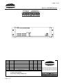
1
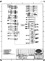
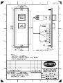
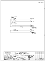
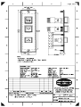
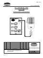
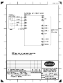
Page 1/63
PHONTECH COMMUNICATION
P.B. 274, 3183 HORTEN NORWAY
PHONE +47 33 08 35 00 FAX +47 33 08 35 01
E-mail : [email protected]
www.phontech.no
HANDBOOK
FOR
PUBLIC ADDRESS SYSTEM
CONCEPT SPA 1500
Rev.2
Page 2/63
PUBLIC ADDRESS SYSTEM SPA-1500
User Manual content
Rev.2
Document no.
Description
Unit
type
Page Page
(pdf) Paper copy
N/A
N/A
96106-000-BD
96106-000-EC
96106-000-DE
96106-000-CO
96106-001-DE
96106-001-ML
96106-001-IW
96106-004-ML
96106-004-IW
96106-005-ML
96106-005-IW
96106-002-DE
96106-002-ML
96106-002-IW
96106-007-CD
96106-007-LO
96106-017-DE
96106-017-ML
96106-017-IW
96106-018-DE
96106-018-ML
96106-018-IW
96106-019-DE
96106-019-ML
96106-019-IW
01100-003-DE
01100-003-ML
01100-003-IW
99100-003-CA
NA
Handbook front page
User Manual content
Block Diagram of SPA-system
External Connection of SPA-system
System Description
Commissioning procedure
Description Operation Unit SPA-1500
Layout of Operation Unit SPA-1500
Internal Wiring of SPA-1500
Layout of SPA-1510
Internal Wiring of SPA-1510
Layout of SPA-1530
Internal Wiring of SPA-1530
Description Control Unit SPA-1501
Layout of Control Unit SPA-1501
Internal Wiring of SPA-1501
Circuit diagram for SPA-1501
Lay out of Circuit board for SPA-1501
Description Alarm Panel SPA-1503
Layout of Alarm Panel SPA-1503
Internal Wiring of SPA-1503
Description Entertainment Unit SPA-1504
Layout of Entertainment Unit SPA-1504
Internal Wiring of Ent. Unit SPA-1504
Description Alarm Panel SPA-1505
Layout of Alarm Panel SPA-1505
Internal Wiring of Alarm Panel SPA-1505
Description Control Unit SPA-1506
Layout of Control Unit SPA-1506
Internal Wiring of Control Unit SPA-1506
Double Alarm Generator w/surveillance
Amplifier PA-9312 and PA-9324
SPA-1500
SPA-1500
SPA-1500
SPA-1500
SPA-1500
SPA-1500
SPA-1500
SPA-1500
SPA-1500
SPA-1510
SPA-1510
SPA-1530
SPA-1530
SPA-1501
SPA-1501
SPA-1501
SPA-1501
SPA-1501
SPA-1503
SPA-1503
SPA-1503
SPA-1504
SPA-1504
SPA-1504
SPA-1505
SPA-1505
SPA-1505
SPA-1506
SPA-1506
SPA-1506
NA
NA
1
2
3
4
5-14
15-16
17-24
25
26
27
28
29
30
31-32
33
34
35
36
37-38
39
40
41-43
44
45
46-47
48
49
50-51
52
53
54-56
57-63
1 of 1
1 of 1
1 of 1
1 of 1
1 - 10
1-2
1-8
1 of 1
1 of 1
1 of 1
1 of 1
1 of 1
1 of 1
1-2
1 of 1
1 of 1
1 of 1
1 of 1
1-2
1 of 1
1 of 1
1-3
1 of 1
1 of 1
1-2
1 of 1
1 of 1
1-2
1 of 1
1 of 1
1-3
1-7
Page 3/63
Page 4/63
Page 5/63
SPA System description
Doc.No.: 96106-000-DE
CONTENTS.
1.0
INTRODUCTION.
2.0
GENERAL DESCRIPTION
2.1
SPA 1500 OPERATION UNIT
2.2
SPA 1501 PA CONTROL UNIT
3.0
TECHNICAL DATA
3.1
SPA 1500 OPERATION UNIT
3.2
SPA 1501 PA CONTROL UNIT
4.0
INSTALLATION
4.1
POWER REQUIREMENTS
4.2
LOUDSPEAKER NETWORK WHEN DISTRIBUTION OF “GA”
4.3
APPROVED LOUDSPEAKERS AND SOUND PRESSURE LEVELS
4.4
CABLE REQUIREMENTS
4.5
MOUNTING / SCREEN TERMINATION
5.0
OPERATING DESCRIPTIONS
5.1
ENTERTAINMENT CONTROL
5.2
ENTERTAINMENT SOURCE A.
5.3
ENTERTAINMENT SOURCE B.
5.4
PAGING
5.5
ATTENTION TONE DING DONG (OPTION)
5.6
ZONE SELECTOR
5.7
AUTOMATIC ZONE SELECTOR
5.8
PRIORITY
5.9
MUTE LOCAL LOUDSPEAKER
5.10 OVERRIDE VOLUME CONTROL
6.0
ALARMS (OPTION)
6.1
ALARM TYPES
6.2
ALARM ACTIVATION / RESET
6.3
ALARM PRIORITY
01
27.06.2006
Revision EM 1058
TBA
PA
TBA
0
-
FINAL DOCUMENTATION
t.ly
tba
t.ly
REASON FOR ISSUE
PREPARED
CHECKED
APPROVED
REV No:
ISSUE DATE
SPA 1500 SYSTEM DESCRIPTION
This document is the property of PHONTECH and
must not be copied or shown to a third person
without our written acceptance. In the interest of
product improvement, PHONTECH reserves the
right to alter specification and design without
notice.
SIZE: A4
UED no: 92
DOC no: 99106-000-DE
FILE NAME:
Page 1 of 10
V:\prosjekt\96106 SPA-1500\DESC\96106-000-DE.doc
96106-000-DE.doc
Page 6/63
SPA System description
Doc.No.: 96106-000-DE
1.0. INTRODUCTION.
The Phontech SPA system is a standard Small Public Address system especially designed
to cover the needs for PA and entertainment distribution on smaller and mid-size ships and
offshore platforms.
The SPA is a very compact design, but never the less the functions are very much like
those in larger familiar systems.
The customer may chose many optional functions/facilities, and thus obtain an almost
tailor made PA system.
As this is regarded as a safety system for passenger vessels (GA broadcasted by
PA) the SPA also can be delivered as a duplicated system. This means two central
units SPA 1500 and separate routing of loudspeakers and flash lights. Also
separate power supply. Operator panels will have separate routing to each SPA
1500. Re. Figure 2 for typical installation setup.
2.0. GENERAL DESCRIPTION.
2.1
OPERATION UNIT SPA 1500:
The SPA 1500 is the central unit in the SPA system. The SPA 1500 contains all the
necessary electronics/logic needed to obtain the functions/facilities in a PA and
entertainment system.
The functions/facilities lists as follows:
- 3 user inputs.
- 1 external PA input (typical PABX line)
- 1 external entertainment audio line input.
- 1 internal entertainment audio line input.
- 1 Car radio cassette/CD player for internal entertainment source. (Option).
- 24 VDC backup supply connection with automatic switching.
- 24 VDC primary supplies input.
- 3 alarm types (externally triggered). (Option).
- 3 amplifier inputs.
- 3 amplifier outputs.
- 3 zone outputs.
- Mute local loudspeaker relays for the 3 users.
- Override volume control outputs for the 3 zones.
- User priority ranking.
- Attention tone (ding dong) for paging. (Optional)
STATUS INDICATOR LEDS
-
Power on led indicator.
Power failure led indicator.
Alarm on led indicator.
Entertainment on led indicator.
PA activity led indicator.
ENTERTAINMENT CONTROL.
3 toggle switches for each entertainment source.
Both sources may be distributed to any of the 3 zones.
The status led " ENT" illuminates.
Page 2 of 10
V:\prosjekt\96106 SPA-1500\DESC\96106-000-DE.doc
Page 7/63
SPA System description
Doc.No.: 96106-000-DE
2.2
PA CONTROL UNIT SPA 1501:
The SPA 1501 is designed especially to operate together with the SPA 1500.
The SPA 1501 is the paging station.
The SPA 1501 is flush mounted, but back-box for wall mounting is optional.
-
Gooseneck microphone as standard.
3 zones select buttons with light indication
1 talk/all buttons with light indication.
Zone/area indicator windows with backlight.
Handheld microphone (Optional instead of gooseneck).
3.0. TECHNICAL DATA.
3.1
OPERATION UNIT SPA 1500:
- 19" 3 HE rack/ console mounting unit.
- Operating voltage: 24 VDC.
- Optional mains supply: 110 VAC to 240 VAC.
- Automatic switch over if mains failure occurs.
- Mic input level:
5mV.
- External PA input level:
0 dBm typical.
- External entertainment input level:
0 dBm typical.
- Amplifier inputs level:
0 dBm typical
- Amplifier output level:
100 V line.
- Zone output level:
100 V line.
- Car cassette radio/CD player. (Optional) for entertainment.
- Rack enclosure. (Option).
3.2
PA CONTROL UNIT SPA 1501:
- Flush mounting.
- Operating voltage:
- Mic line audio level:
- Led indicators for all keys.
- Backlight led`s for area text.
- Withstands rough and moist environment.
Page 3 of 10
V:\prosjekt\96106 SPA-1500\DESC\96106-000-DE.doc
24 VDC.
5 mV.
Page 8/63
SPA System description
Doc.No.: 96106-000-DE
4.0. INSTALLATION:
The SPA system is adapted to fit rack mounting 19", and standardized dimensions in
modern ship consoles.
The system may be delivered with rack enclosure. The racks are from 6HE in the smallest
configuration (SPA 1510) up to 12 HE in the biggest version (SPA 1530).
Depth of all rack-mounted units is 600 mm.
4.1 POWER REQUIREMENTS:
The operating power is 24 VDC.
Optional power is 110>230 VAC 50 Hz.
4.2 LOUDSPEAKER NETWORK WHEN DISTRIBUTION OF “GA”
• Loudspeaker network arranged as a closed loop.
• Or with fuses/brakers or electrical protection provided at each deck such that
failure/short circuit in any deck does not affect other decks or the central unit.
4.3 APPROVED LOUDSPEAKERS AND SOUND PRESSURE LEVELS
• Loudspeakers to be of 100V line, proven marine design according to IEC60945 and
suitable for the selected positions. Sound pressure level to be minimum as required
by IMO/Solas & class.
• Sound pressure level during alarm:
o Interior and exterior spaces: 80dbA and at least 10dbA above ambient noise
levels.
o In sleeping positions and cabin bathrooms: 75dbA and at least 10dbA above
ambient noise levels.
o The input level from the tone generator shall be adjusted such that full power
is used for the alarm tones (near 100V to the loudspeakers).
• Sound pressure level during Public address:
o Speech in low noise areas: RASTI/STI = 0,7, applicable in recreation areas,
offices, sleeping cabins and similar.
o Speech in high noise areas: RASTI/STI = 0,35, applicable in noisy areas with
up to 85dbA noise level. In areas with background noise level of 86dbA or
more, alarm signals and emergency messages shall be complemented by
flashing lights.
o An ideel voice message is obtained when the S/N is more than 30db.
4.4 CABLE REQUIREMENTS:
The 24 VDC power supply cable conductor area is 4 sqmm.
The 110>230 VAC cable conductor area is 1,5 sqmm.
All signal cables must be twisted pairs with outer screen.
All signal cables conductor area is 1,5 sqmm.
Do not combine different systems in the same cable. This to prevent disturbance and noice
due to interference.
Page 4 of 10
V:\prosjekt\96106 SPA-1500\DESC\96106-000-DE.doc
Page 9/63
SPA System description
Doc.No.: 96106-000-DE
4.5 MOUNTING/ SCREEN TERMINATION:
SPA 1500 operation unit is mounted in a 19" standard rack or console, and fixed with front
bolts.
For flush mounting: cut-out dimensions is 130 x 445 mm (h x w)
Cable inlet from behind.
SCREEN CONNECTION.
In order to obtain maximum performance after installation, it is important to terminate the
cables and ground the screens in a good manner.
The cables are to be de- isolated by removing the outer insulation. Then the screen braid is
cut off app. 30mm longer than the outer isolation.
The conductor is de-isolated and fitted with end-crimps before they are screwed on to the
terminal.
The outer screen, which now is open, is clamped onto the cable fixing arcs inside the
cabinet. Cable ties of conductive type are recommended for best result.
Please see figure 3 on page 10 for more details.
SPA 1501 pa control unit is flush mounted in standardized measurement ship consoles.
For other flush mounting: cut-out dimensions are 90 x 123 mm.
Cable inlet from behind.
To ease the cable termination the screw terminals are plug-in type.
Page 5 of 10
V:\prosjekt\96106 SPA-1500\DESC\96106-000-DE.doc
Page 10/63
SPA System description
Doc.No.: 96106-000-DE
5.0. OPERATING DESCRIPTION.
The SPA includes both an entertainment and a public address system.
The entertainment system is operated and controlled at the operation unit SPA 1500.
The car cassette radio/CD player serves as one of the entertainment sources. (SOURCE A)
One additional entertainment audio source may be incorporated into the system.
(SOURCE B)
5.1 ENTERTAINMENT CONTROL
Both sources are routed to the selected zone by means of the entertainment control at the
SPA 1500.
As soon as any of the toggle switches is activated the ENT. led in the STATUS panel is lit.
IMPORTANT
DO NOT ACTIVATE BOTH SOURCES IN THE SAME ZONES SIMULTANEOUSLY.
THIS WILL MIX THE AUDIO INTO THE LOUDSPEAKERS.
5.2 ENTERTAINMENT SOURCE A.
The car cassette radio/CD player (Option) serves as entertainment source A.
Switch the car radio on, tune to a strong station and route the signal to the desired zone.
(See 5.0 and 5.1)
5.3 ENTERTAINMENT SOURCE B.
The entertainment source B is an external audio line from e.g. a TV / video system.
Make sure the signal is present, and operate as in 5.0 and 5.1.
5.4 PAGING
Paging is possible from any of the three PA CONTROL UNITS SPA 1501, and from an
EXTERNAL PA source, typical a PABX line.
Paging may be performed in any of the three zones, or all zones. See 5.6 and 5.7.
Press the TALK key and speak clearly and directly into the microphone.
PA messages should always be as brief as possible.
PA messages should also be of "non-personal" kind, since this message is public.
PA messages should be repeated once to ensure the message is received.
Also see 5.5.
5.5 ATTENTION TONE DING DONG (OPTIONAL)
When paging is performed an attention tone (ding-dong) will be distributed over the
loudspeakers in the actual zone.
Note the attention tone is optional, and requires a module mounted in the SPA 1500.
The duration of this attention tone is approximately 2 seconds, therefore wait at least 2
seconds prior to paging.
5.7 AUTOMATIC ZONE SELECTOR
The PA CONTROL UNIT SPA 1501 has three zone keys plus one TALK/ALL key.
As one of the zone keys is activated, the indicator led illuminates full light.
If none of the zone keys is active (half-light), and the TALK/ALL key is operated,
the system AUTOMATICALLY goes into ALL CALL mode.
I.e. all the zone key indicator leds illuminates full light and the message is distributed in ALL
ZONES.
Page 6 of 10
V:\prosjekt\96106 SPA-1500\DESC\96106-000-DE.doc
Page 11/63
SPA System description
Doc.No.: 96106-000-DE
5.8 PRIORITY
The SPA system incorporates user priority. The priority ranking is:
1.
2.
3.
4.
5.
USER 1 (SPA 1501)
USER 2 (SPA 1501)
USER 3 (SPA 1501)
EXTERNAL PA
ENTERTAINMENT
The alarm (Option) has top priority. I.e. an alarm will override all PA, and the user looses
access.
The user however will regain his access by releasing his TALK key and then press it once
more.
5.9 MUTE LOCAL LOUDSPEAKER
Each user (3) has one "mute local loudspeaker" circuit.
The users local speaker may be routed through this circuit to obtain undistorted PA
messages.
This will minimize the risk of audible feedback, and ensure safe operation.
5.10 OVERRIDE VOLUME CONTROL
Each zone has one "override volume control" output.
In an entertainment system it is convenient to have local volume controls at the
loudspeaker.
A PA message or alarm however is important to be distributed at full volume to ensure
safe operation.
The "override volume control" output is to be utilized for this function.
6.0. ALARMS (OPTION)
The SPA system may comprise an alarm tone generator board. (Option).
This board has three different alarm types.
Active alarm is indicated in the status panel by illuminated ALARM led.
6.2 ALARM ACTIVATION / RESET.
The alarms may be automatically (F&G panel) activated / reset.
Alternatively an alarm control panel may be connected panel.
6.3 ALARM PRIORITY.
The alarm signal has top priority.
I.e. an active alarm will break down any PA message or entertainment audio.
The PA user may regain access by releasing the talk key and press it once more.
Page 7 of 10
V:\prosjekt\96106 SPA-1500\DESC\96106-000-DE.doc
Page 12/63
SPA System description
Doc.No.: 96106-000-DE
PHONTECH
PHONTECH
1
1
2
3
2
L LK
AL TA
SPA 1501
3
L LK
AL TA
SPA 1501
ZONE 1
1
ZONE 2
2
ZONE 3
3
L LK
AL TA
SPA 1506
Figure 1 – Standard single system
Page 8 of 10
V:\prosjekt\96106 SPA-1500\DESC\96106-000-DE.doc
Page 13/63
SPA System description
Doc.No.: 96106-000-DE
Figure 2 – Duplicated system (A/B-system)
Page 9 of 10
V:\prosjekt\96106 SPA-1500\DESC\96106-000-DE.doc
Page 14/63
SPA System description
Doc.No.: 96106-000-DE
FIGURE 3
The cable outer screen is to be terminated as shown. Conductive type of cable ties is
recommended to obtain best possible screen connections.
Page 10 of 10
V:\prosjekt\96106 SPA-1500\DESC\96106-000-DE.doc
Page 15/63
PHONTECH
Doc.No.: 96106-000-CP
COMMISSIONING PROCEDURE
FOR
SPA-1500 SYSTEM
1. CHECK THAT CABLING IS ACCORDING TO APPROVED DRAWINGS.
2. USE SPA-1501 UNIT TO ACCESS ZONE 1 TO 3 AND VERIFY AUDIO IN
THE CORRESPONDING SPEAKERS. ALSO VERIFY 24VDC VOLUME
OVERRIDE OUTPUT FOR ZONE 1-3(TERM.15/16,17/18,33/34) IF IN USE.
3. ACTIVATE ENTERTAINMENT IF INSTALLED AND VERIFY THAT IT’S
DISTRIBUTED TO THE SELECTED ZONE.(SWITCHES IN FRONT)
4. IF AN ALARMCARD IS INSTALLED TEST THAT BOTH ALARMS IS
DISTRIBUTED TO ALL ZONES AND CAN BE OVERRIDED BY THE
ACCESS PANEL(S) 1501.(USER1 TO USER 3 AND EXTERNAL INPUT)
5. IF AN ALARMCARD OR DING-DONG CARD IS INSTALLED EACH
ANNOUNCEMENT COULD START WITH A PRETONE.
6. IF THE EXTERNAL INPUT IS IN USE, THEN CHECK THAT THE AUDIO
IS DISTRIBUTED TO THE PRESELECTED ZONES(DIPSWITCH S7 1-3)
7. IF EXTERNAL OUTPUT(AUDIO/KEY) IS IN USE, VERIFY AUDIO IS
PRESENT AT TERMINALS 100/101 REGARDLESS OF THE ZONE SELECTIONS.
KEY 1 AND 2 OUTPUT IS POTENSIAL FREE RELAY CONTACTS.
KEY 1 TERM 103/104/105, KEY 2 TERM 106/107/108. THESE CONTACTS
ACTIVATES WHEN ALL ZONES ARE ACTIVE
PHONTECH
0
REV No:
05.02.02
ISSUE DATE
CUSTOM REQUIRE
AHJ
TEH
AHJ
REASON FOR ISSUE
PREPARED
CHECKED
APPROVED
TITLE:
COMMISSIONING PROCEDURE
This document is the property of PHONTECH and
must not be copied or shown to a third person
without our written acceptance. In the interest of
product improvement, PHONTECH reserves the
right to alter specification and design without
notice.
SIZE: A4
UED no:
DOC no: 96106-000-CP
FILE NAME:
Page 1 of 2
V:\prosjekt\96106 SPA-1500\DOC\Com_procedure.doc
Com_procedure.doc
Page 16/63
PHONTECH
Doc.No.: 96106-000-CP
ITEM
Page 2 of 2
ACCEPTED (YES/NO)
COMMENTS
Page 17/63
Doc.No.: 96106-001-DE
TITLE:
SPA SYSTEM
OPERATION UNIT SPA 1500
DESCRIPTION
This document is the property of DOC. NO:
PHONTECH AS, and must not be
copied or shown to a third party 96106-001-DE
without our written acceptance.
In the interest of product improvement FILE:
PHONTECH AS reserves the right to
alter the specification and design
96106-001-DE
UED No :
92
REF:
DATE
961021
2
778
AUTH.
t.ly
1
636
0
-
CHK.
APPR
Page 1 of 8
W:\Handbøker Skip\1. SPA 1500\DESCR\96106-001-DE.doc
REV
CO
00/04
17
97/03
06
97/02
05
t.ly
t.ly
t.ly
DATE SIGN
Page 18/63
Doc.No.: 96106-001-DE
CONTENTS.
1.0. INTRODUCTION.
2.0. GENERAL DESCRIPTION.
3.0. SYSTEM BOARD FOR SPA 1500.
3.1. AUDIO ROUTING .
3.2. PRIORITY.
3.3. ZONE SELECTOR LOGIC.
3.4. EXTERNAL PA ZONE SELECTOR.
3.5. AMPLIFIER>ZONE PRESET.
3.6. EXTERNAL EQUIPMENT AUDIO OUTPUT.
4.0. OPTIONAL ALARM BOARD INSTALLED.
5.0. OPTIONAL DING-DONG BOARD INSTALLED.
6.0. AUTOMATIC GAIN CONTROL (AGC) DISABLE.
7.0. ENTERTAINMENT MUTE.
8.0. CAR CASSETTE RADIO/ CD PLAYER
10.0. DC CONVERTER.
11.0. ENTERTAINMENT CONTROL.
12.0. STATUS LEDS.
Page 2 of 8
W:\Handbøker Skip\1. SPA 1500\DESCR\96106-001-DE.doc
Page 19/63
Doc.No.: 96106-001-DE
1.0. INTRODUCTION.
A pa and entertainment system consist of PA control units, operation unit, and the
amplifiers.
The operation unit SPA 1500 is the central unit in a SPA system.
The compact design makes it easy to install. The mounting is in standard 19" rack or
console.
All the electronics and logic required is located in the SPA 1500.
The amplifiers may be placed away from the SPA 1500, but this requires more cabling.
2.0. GENERAL DESCRIPTION.
The SPA 1500 is in max version is comprising the following parts:
- System board for SPA 1500.
- Car cassette radio/ CD player. (option)
- Power supply for 110 > 230 VAC (option)
- DC converter for the car radio.(option)
- Entertainment control panel.
- Status panel leds.
- Screw terminals for power and signal cables.
3.0. SYSTEM BOARD FOR SPA 1500.
This PCB contains all the electronic parts required in an operation unit.
The below description refers to drawing 96106-006-CD.
3.1. AUDIO ROUTING.
The 3 microphone line inputs are routed through the user audio switching relays RE1-RE3 to
the preamplifier (M19,M20) with automatic gain control. The preamp. raises the audio from
microphone level to approximately 0 dBm. (775 mV)
0 dBm is the appropriate level to the power amplifier inputs.
The external pa audio interface is on 0dBm level, and goes through RE4 directly to the audio
buffer.
Attention tone ding-dong board. (option.)
This circuit board generates a ding-dong sound in the loudspeakers prior to a PA message.
An active TALK/ KEY signal from the three users or the external pa source starts the
ding-dong generator.
Note that the ding-dong only work in PA mode, entertainment does not start the ding-dong.
Alarm tone generator board ( option ).
The alarm is an optional facility. There are three different alarm sounds available in the
system.
The alarms are started and stopped from an external control panel or from automatic alarm
panels like a fire detector panel.
Page 3 of 8
W:\Handbøker Skip\1. SPA 1500\DESCR\96106-001-DE.doc
Page 20/63
Doc.No.: 96106-001-DE
Audio buffer (M20). The above described audio sources, speech, ding-dong and alarm are
added into one audio buffer. From this buffer the audio goes through the amplifier input
relays (RE6-RE8) to the amplifiers.
The amplifier outputs are fed back to the operation unit for zone switching.
From the zone relays RE9-RE11 the output goes to the loudspeaker network.
See below for an overview over the trimmer potmeters and the dipswitches location onboard
the PCB 96106-006.
This board is mounted inside the operation unit SPA 1500.
Page 4 of 8
W:\Handbøker Skip\1. SPA 1500\DESCR\96106-001-DE.doc
Page 21/63
Doc.No.: 96106-001-DE
EXTERNAL PA ZONE PRESET: The first 3 switches on dipswitch S7 is for the external PA zone
preset (typical PABX)
AMP/ZONE INPUT PRESET:
The last 3 switches on dipswitch S7 is for the amplifier 1 zone.
The three first switches on dipswitch S8 is for the amplfier 2 zones.
The three last switches on dipswitch S8 is for the amplifier 3 zones.
ENT/AMP ZONE PRESET:
The dipswitches S9,S10;S11 is for the entertainment amplifier
zoning. (see description in this document on page 6).
SPEECH LEVEL POT:
Common trimmer potentiomenter for the users 1,2,and,3.
EXT PA LEVEL POT:
Trimmer for the external PA audio level. (typical PABX etc.)
ENTERTAINMENT “A” LEVEL POT: Trimmer for the entertainment source A audio level.
(typical internal car radio)
ENTERTAINMENT “B” LEVEL POT: Trimmer for the entertainment source B audio level.
(typical an external source)
AMP/ZONE OUTPUT STRAPS: Strapping field for the amplifier output to zones strapping.
3.2. PRIORITY.
The system includes user priority.
The priority ranking is fixed. Therefore the users connection into the system board must be
decided according to the desired priority ranking.
The ranking is as follows:
1.
2.
3.
4.
PRIORITY
PRIORITY
PRIORITY
PRIORITY
USER 1
USER 2
USER 3
EXT. PA.
3.3. ZONE SELECTOR LOGIC.
The system includes three PA / ENT zones.
The user panels has three zone selector keys.
If none of the zones are selected the system automatically select all three zones. (all call)
3.4. EXTERNAL PA ZONE SELECTOR.
The external pa input does not have zone select possibility.
Therefore this set-up must be preset.
This is decided on the dip-switch S7.
S7 SWITCH
S7 SWITCH
S7 SWITCH
The location
1 = ZONE 1
2 = ZONE 2
3 = ZONE 3
of the different dip-switches aso. is indicated on page 4. fig. 1.
Page 5 of 8
W:\Handbøker Skip\1. SPA 1500\DESCR\96106-001-DE.doc
Page 22/63
Doc.No.: 96106-001-DE
3.5. AMPLIFIER>ZONE PRESET.
Due to the fact that the amplifiers can be dedicated to different zones, both the input and
the
output routing must be totally flexible.
Both the entertainment input and the PA input must be strapped / preset in accordance to
the tables on page 6.
The location of the different dip-switches aso. is indicated on page 4. fig.1.
3.6. EXTERNAL EQUIPMENT AUDIO OUTPUT.
The circuitry includes an external audio output line with dual dry contact relay contacts for
keying.
The nominal audio level is 0dbm.
This audio output includes speech from all users plus alarms.
Note the two key contacts only operate in an all-call situation in the PA system.
I.e. the user has selected all-call, or in an alarm situation.
(alarm enabled automatically operates all zones, all-call )
TABLE 1. TYPICAL CONFIGURATION.
1 = CLOSED STRAP/SWITCH ON
O = OPEN STRAP/SWITCH OFF
X = DON`T CARE
NUMBER
OF AMPS.
DIPSWITCH 7
12345678
DIPSWITCH 8
12345678
DIPSWITCH 9
12345678
A
B
111000XX
DIPSWITCH 10
12345678
A
B
000000XX
DIPSWITCH 11
12345678
A
B
000000XX
OUTPUT STRAPS
1 2 3 4 5 6 7 8 9 10 11 12 13 14 15 16 17 18
1
---111XX
000000XX
2
---100XX
011000XX
100000XX
011000XX
000000XX
110000001 1
1
1
0
0
0
0
0
0
2)
3
---100XX
010001XX
100100XX
010010XX
001001XX
110000001 1
0
0
0
0
0
0
1
1
3)
111111000 0
0
0
0
0
0
0
0
0
NOTE
1)
Note 1) One amplifier cover all three zones. Only entertainment A present. Entertainment possible in all zones.
Note 2) One amplifier on zone 1, one amplifier cover zone 2 and 3.
Note 3) One amplifier for each zone. Two entertainment sources. Both sources (A+B) possible in all zones.
TABLE 2. EXAMPLE.
NUMBER
OF AMPS.
DIPSWITCH 7
12345678
DIPSWITCH 8
12345678
DIPSWITCH 10
12345678
A
B
000000XX
DIPSWITCH 11
12345678
A
B
000000XX
OUTPUT STRAPS
1 2 3 4 5 6 7 8 9 10 11 12 13 14 15 16 17 18
000000XX
DIPSWITCH 9
12345678
A
B
111000XX
1
---111XX
2
---110XX
3
---100XX
111111000 0
0
0
0
0
0
0
0
0
1)
001000XX
110000XX
001000XX
000000XX
110000000 0
1
1
0
0
0
0
0
0
2)
010001XX
100100XX
010010XX
001001XX
110000001 1
0
0
0
0
0
0
1
1
3)
Page 6 of 8
W:\Handbøker Skip\1. SPA 1500\DESCR\96106-001-DE.doc
NOTE
Page 23/63
Doc.No.: 96106-001-DE
Note 1) One amplifier cover all zones. Only entertainment A present. Entertainment possible in all zones.
Note 2) One amplifier zone 1 and 2. One amplifier zone 3.
Note 3) One amp per zone. Two entertainment sources. Both sources ( A+B) possible in all zones.
4.0. OPTIONAL ALARM BOARD INSTALLED.
The SPA 1500 may have an alarm tone generator board installed.
The alarm board may be the std. PCB 92100-027, or the duplicated alarm board 99100-003.
In this case the ST 20 is to be mounted.
The ST 21 is removed.
5.0. OPTIONAL DING-DONG BOARD INSTALLED.
The SPA 1500 may have a ding-dong board installed.
PCB 88100-014.
In this case the ST 19 is to be mounted.
The ST 21 is mounted.
6.0. AUTOMATIC GAIN CONTROL (AGC) DISABLE.
The AGC may be disabled for special purposes.
The ST 22 is installed in this case.
7.0. ENTERTAINMENT MUTE.
If the SPA system is single amplifier based the entertainment zone set-up must be disabled
during PA paging. The ST 23 is removed.
If the system includes one amplifier per zone the entertainment and PA is separated, and
simultaneous operation is possible. The ST 23 is mounted.
If one of the amplifiers is combined in two zones the ST 23 is removed.
8.0. CAR CASSETTE RADIO/ CD PLAYER
The SPA 1500 may be delivered with an optional car cassette radio / CD player.
This unit serves as the entertainment source A in the system.
9.0. POWER SUPPLY.
The SPA 1500 operates on 24 VDC supply. The system board has two power line inputs.
One is supply directly from the ships batteries, the other from the optional net adapter.
(option)
The AC supply may span from 110 to 230 VAC without having to do any re-wiring in the
power supply.
10.0. DC CONVERTER.
The car cassette radio is operating on 12 VDC. This voltage is supplied from the DC
converter. (option)
Page 7 of 8
W:\Handbøker Skip\1. SPA 1500\DESCR\96106-001-DE.doc
Page 24/63
Doc.No.: 96106-001-DE
11.0. ENTERTAINMENT CONTROL.
The entertainment sources is controlled by means of the entertainment control switches on
the front at the SPA 1500. There are three toggle switches for the A source zoning
configuration, and three toggle switches for the B source zoning configuration.
12.0. STATUS LEDS.
The system status is displayed on the STATUS part of SPA 1500.
Led for supply status: POWER led. Green colour means OK. Red colour means mains (110220VAC) failure.
Led for PA activity:
PA led. Illuminates when the system is active in PA mode.
(Paging from users/ PABX etc.)
Led for entertainment:
ENT. led. Illuminates when any of the six entertainment
switches is active.
Led for alarm.
ALARM led. Illuminates if the alarm is active. (Alarm is optional)
Page 8 of 8
W:\Handbøker Skip\1. SPA 1500\DESCR\96106-001-DE.doc
Page 25/63
Page 26/63
Page 27/63
Page 28/63
Page 29/63
Page 30/63
Page 31/63
PHONTECH
Doc.no : 96106-002-DE.doc
PA CONTROL UNIT
SPA 1501
WITH GOOSENECK MICROPHONE
1
2
3
L LK
AL TA
SPA 1501
PHONTECH
0
REV No:
TITLE:
2004.03.01.
ISSUE DATE
FINAL DOCUMENTATION
REASON FOR ISSUE
D.A.
TBA
ASk
PREPARED
CHECKED
APPROVED
PA CONTROL UNIT, SPA 1501.
WITH GOOSE NECK MICROPHONE.
DESCRIPTION.
This document is the property of PHONTECH and
must not be copied or shown to a third person
without our written acceptance. In the interest of
product improvement, PHONTECH reserves the
right to alter specification and design without
notice.
SIZE:
A4
UED no: 92
DOC no: 96106-002-DE
FILE NAME: 96106-002-DE
Page 1 of 2
V:\prosjekt\96106 SPA-1500\1501\DESC\96106-002-DE.doc
Page 32/63
PHONTECH
Doc.No.: 96106-002-DE
GENERAL DESCRIPTION.
The SPA 1501 is a PA control unit in the SPA system. The SPA 1501 contains all the necessary
electronics/logic needed to obtain the function to control the SPA system.
The SPA 1501 is designed for flush or wall mounting.
A wall mounted back box (01100-006) optional.
•
•
•
•
•
Mic. line audio level:
Led indicators for all keys.
Backlight leds for area text.
Replaceable zone description text.
Withstands ruff and moist environment.
5mV.
POWER REQUIREMENTS:
Operating power (included in the SPA1500 connection):
24VDC / 100mA
CABLE REQUIREMENTS:
The signal cable must be twisted pair with outer screen.
Number of pairs:
Conductor area:
4
0.75mm2
MOUNTING:
Spa 1501 PA control unit is flush mounted in standardized dimension ship consoles.
For other flush mounting: Cut-out dim. 90 x 123 mm.
Cable inlet is from behind.
To ease the cable termination the screw terminals are plug-in type.
PAGING:
Paging may be performed in any of the three zones, or all zones.
Press the TALK key on the handheld microphone and speak clearly and directly into the microphone.
AUTOMATIC AND MANUAL ZONE SELECTION.
The PA control unit, SPA 1501 has three zone keys plus one TALK/ALL key.
When one of the zone keys is activated, the indicator led illuminates full light.
If none of the zones is active (half-light), and the TALK/ALL key is operated, the system
automatically goes into ALL CALL mode.
I.e. all the zone key indicator leds illuminates full light and the message is distributed in ALL ZONES.
Page 2 of 2
V:\prosjekt\96106 SPA-1500\1501\DESC\96106-002-DE.doc
Page 33/63
Page 34/63
Page 35/63
Page 36/63
Page 37/63
PHONTECH
Doc.No.: 96106-017-DE
PA ALARM PANEL
SPA-1503
DESCRIPTION
PHONTECH
0
REV No:
05021997
ISSUE DATE
FINAL DOCUMENTATION
Tly
ASk
TBA
REASON FOR ISSUE
PREPARED
CHECKED
APPROVED
TITLE: PUBLIC ADDRESS SYSTEM.
ALARM PANEL, SPA-1503.
DESCRIPTION.
This document is the property of PHONTECH and
must not be copied or shown to a third person
without our written acceptance. In the interest of
product improvement, PHONTECH reserves the
right to alter specification and design without
notice.
SIZE:
DOC no:
A4
UED no: 92
96106-017-DE
FILE NAME: 96106-017-DE.DOC
Page 1 of 2
Page 38/63
PHONTECH
Doc.No.: 96106-017-DE
GENERAL DESCRIPTION.
The SPA-1503 is the alarm panel in the SPA system.
The SPA-1503 is directly connected to the operation unit SPA-1500.
The SPA-1503 is normally connected to the general alarm input on the SPA-1500.
The SPA-1503 is designed for flush mounting.
To prevent starting the alarm unintended, the general alarm button is protected by
a hinged cover.
POWER REQUIREMENTS:
Operating power: (light emitting diode power)
24 VDC.
CABLE REQUIREMENTS:
Number of pairs:
Conductor area:
3
1,5 sqmm.
MOUNTING:
SPA-1503 alarm panel is flush mounted in standardised dimension ship consoles.
For other flush mounting: cut-out dimensions is 34 x 123 mm.
Cable entry from behind.
ALARM CONTROL:
The alarm in the SPA system may be started/stopped automatically, or manually from
the SPA-1503.
Only the GENERAL ALARM may be started from the SPA-1503, lamp indication for
started alarm.
FIRE ALARM status may be monitored in the FIRE ALARM lamp.
SEVERAL ALARM PANELS IN THE SYSTEM:
If several SPA-1503 is to be incorporated in the syste, the input “REMOTE
INDICATOR GENERAL ALARM” may be utilised to obtain internal monitoring.
Half-light in the general lamp indicate that other alarm panel has started the alarm.
ALARM ZONES:
The SPA-1503 automatically distribute the alarm audio to all the zones.
Page 2 of 2
Page 39/63
Page 40/63
Page 41/63
PHONTECH
Doc.No.: 96106-018-DE
DUAL ENTERTAIMENT UNIT
SPA-1504
DESCRIPTION
PHONTECH
0
REV No:
12121997
ISSUE DATE
FINAL DOCUMENTATION.
Tly
ASk
TBA
REASON FOR ISSUE
PREPARED
CHECKED
APPROVED
TITLE: PUBLIC ADDRESS SYSTEM.
DUAL ENTERTAINMENT UNIT, SPA-1504.
DESCRIPTION.
This document is the property of PHONTECH and
must not be copied or shown to a third person
without our written acceptance. In the interest of
product improvement, PHONTECH reserves the
right to alter specification and design without
notice.
SIZE:
A4
DOC no:
FILE NAME:
Page 1 of 3
UED no: 92
96106-018-DE
96106-018-DE.DOC
Page 42/63
PHONTECH
Doc.No.: 96106-018-DE
INTRODUCTION:
The SPA-1504 Dual Entertainment Unit was designed to operate the Phontech SPAsystem. Together with the SPA-1510 or SPA-1530 it will be a complete public address
and entertainment system.
The compact design makes it easy to install.
The mounting is in standard 19” rack or console.
GENERAL DESCRIPTION:
The SPA-1504 is in maxversion comprising the following parts:
-2 pcs. Car cassette radio/CD players.
-Power supply for 110>230 VAC (option).
-DC converter for the car radios/CD players.
-Dual antenna input.
OPERATION:
The entertainment sources may be the radio, the cassette player or the CD player.
The type of car receiver installed is project dependent.
RADIO SOURCE:
Turn the radio on and tune to the desired station. The output level is adjustable by
means of the volume control buttons/knob.
Please see the user manual for the attached car radio model for further information.
MUSIC CASSETTE SOURCE:
This source is comprehensive when pre-recorded public address message is to be
broadcasted over the loudspeakers. For entertainment purposes this also can give around
the clock music, by means of the auto reverse function.
Please see the user manual for the attached car radio model for further information.
CD PLAYER SOURCE:
High quality entertainment audio sound is accomplished when using the CD-player.
Some players has random play. Around the clock entertainment is reached by enabling
the replay function at the CD-player.
Please see the user manual for the attached car radio model for further information.
Page 2 of 3
Page 43/63
PHONTECH
Doc.No.: 96106-018-DE
TECHNICAL DATA:
-Operation voltage:
-Current drain:
24 VDC. (230 VAC optional).
3A max.
-Capacity:
-Line out audio level:
two car radio/CD/cassette players.
500-700 mV.
-Mounting:
-Dimension:
-Weight:
3HE/19” rack or console mounting.
W: 483 / H: 132,50 / D: 282 mm.
<4 kgs.
Page 3 of 3
Page 44/63
Page 45/63
Page 46/63
PHONTECH
Doc.No.: 96106-019-DE
PA ALARM PANEL
SPA-1505
DESCRIPTION
PHONTECH
PHONTECH
0
REV No:
23111999
ISSUE DATE
FINAL DOCOMENTATION
Tly
A.I.
ASk
REASON FOR ISSUE
PREPARED
CHECKED
APPROVED
TITLE: PUBLIC ADDRESS SYSTEM.
ALARM PANEL, SPA-1505.
DESCRIPTION.
This document is the property of PHONTECH and
must not be copied or shown to a third person
without our written acceptance. In the interest of
product improvement, PHONTECH reserves the
right to alter specification and design without
notice.
SIZE:
DOC no:
A4
UED no: 92
96106-019-DE
FILE NAME: 96106-019-DE.DOC
Page 1 of 2
Page 47/63
PHONTECH
Doc.No.: 96106-019-DE
GENERAL DESCRIPTION.
The alarm panel SPA-1505 is a panel intended for flush mounting either separately or in
combination with the control unit SPA-1501. It is based on 144 mm standard module
height, 48 mm wide.
The alarm panel consists of 2 alarm buttons with integrated light indicators and a third
light indicator for a remote controlled alarm.
The alarm button indicators also have a remote control indication mode where they will
light with reduced strength.
Then the alarm is overridden by own activation it will light with full intensity.
Both alarm buttons have mechanical alternate functionality. When connected to the
SPA-1500 the termination will decide the priority of the alarm signal.
Phontech recommend the wiring indicated in the document 96106-019-EC.
This will make the priority according to IMO regulation like this:
1.
2.
3.
General Alarm.
Fire alarm (remotely controlled from an automatic fire and gas system).
Alarm 2 (customer requirements/delivered upon request).
All alarm setting outputs and indicator inputs are based on 24 VDC supply with closing
contacts to 0V.
Page 2 of 2
Page 48/63
Page 49/63
Page 50/63
PHONTECH
Doc.No.: 01100-003-DE
PA CONTROL UNIT
SPA 1506
WITH HANDHELD MICROPHONE
ZONE 1
1
ZONE 2
2
ZONE 3
3
K
LL L
A TA
SPA 1506
PHONTECH
0
REV No:
2001.11.15
ISSUE DATE
FINAL DOCUMENTATION
REASON FOR ISSUE
R.F.
TBA
ASk
PREPARED
CHECKED
APPROVED
TITLE: PA CONTROL UNIT, SPA 1506.
WITH HANDHELD MICROPHONE.
DESCRIPTION.
This document is the property of PHONTECH and
must not be copied or shown to a third person
without our written acceptance. In the interest of
product improvement, PHONTECH reserves the
right to alter specification and design without
notice.
SIZE:
A4
UED no: M025
DOC no: 01100-003-DE
FILE NAME: 01100-003-DE
Page 1 of 2
Page 51/63
PHONTECH
Doc.No.: 01100-003-DE
GENERAL DESCRIPTION.
The SPA 1506 is a PA control unit in the SPA system. The SPA 1506 contains all the necessary
electronics/logic needed to obtain the function to control the SPA system.
The SPA 1506 is designed for flush or wall mounting.
A wall mounted back box (01100-006) optional.
•
•
•
•
•
Mic. line audio level:
Led indicators for all keys.
Backlight leds for area text.
Replaceable zone description text.
Withstands ruff and moist environment.
5mV.
POWER REQUIREMENTS:
Operating power (included in the SPA1500 connection):
24VDC / 100mA
CABLE REQUIREMENTS:
The signal cable must be twisted pair with outer screen.
Number of pairs:
Conductor area:
4
0.75mm3
MOUNTING:
Spa 1506 PA control unit is flush mounted in standardized dimension ship consoles.
For other flush mounting: Cut-out dim. 90 x 123 mm..
Cable inlet is from behind.
To ease the cable termination the screw terminals are plug-in type.
PAGING:
Paging may be performed in any of the three zones, or all zones.
Press the PTT key on the handheld microphone and speak clearly and directly into the microphone.
(The PTT button on the panel will not work properly with a handheld mic.)
AUTOMATIC AND MANUAL ZONE SELECTION.
The PA control unit, SPA 1506 has three zone keys plus one TALK/ALL key.
When one of the zone keys is activated, the indicator led illuminates full light.
If none of the zones is active (half-light), and the TALK/ALL key is operated, the system
automatically goes into ALL CALL mode.
I.e. all the zone key indicator leds illuminates full light and the message is distributed in ALL ZONES.
Page 2 of 2
Page 52/63
Page 53/63
Page 54/63
PHONTECH
Doc.No.: 99100-003-CA
CARD DESCRIPTION
DOUBLE ALARM GENERATOR WITH SURVEILLANCE
99100-003
PHONTECH
0
REV No:
23.11.1999
ISSUE DATE
FINAL DOCUMENTATION.
ASk
A.I.
ASk
REASON FOR ISSUE
PREPARED
CHECKED
APPROVED
TITLE: DOUBLE ALARM GENERATOR.
WITH SURVEILLANCE.
Card Description.
This document is the property of PHONTECH and
must not be copied or shown to a third person
without our written acceptance. In the interest of
product improvement, PHONTECH reserves the
right to alter specification and design without
notice.
SIZE:
A4
DOC no:
FILE NAME:
Page 1 of 3
UED no: M009
99100-003-CA
99100-003-CA.DOC
Page 55/63
PHONTECH
Doc.No.: 99100-003-CA
GENERAL FACILITIES:
The DOUBLE ALARM GENERATOR WITH SURVEILLANCE – 99100-003 is an
alarm generator module comprising 2 totally independent generator sections.
The digital in- and outputs as well as the primary audio output are however common to
both generators.
Even so they are isolated in such way they will not interfere with normal operation in
case of any single accident/failure.
The generator is fully microprocessor controlled and thus very flexible.
It can be pre-programmed to most requirements.
In many applications it can also be user-configured to meet the required performance.
In addition to be full duplication of the generator it is equipped with various supervision
facilities:
•
•
•
•
•
Input power supply-supervision guard below 15-18 V. (Software processed).
Supervision of the opposite generator operation voltage, above 4.6 V.
(Software processed).
Supervision of the signal output voltage, above 325 mV. Software processed).
Supervision of the generators own operation voltage, above 4.5 V. This circuit
will also protect the circuit from unintentional stops caused by power supply
glitches. (Hardware processed).
A Watchdog circuit monitoring the microprocessor and software performance
in order to avoid any lockups. (Hardware processed – software trigged).
Level adjustment:
The signal output voltage is a common passive summarisation output for both signal
generators. Both generator modules have separate level adjustment ranging between 01.5 V RMS. In order to avoid fault conditions caused by the output signal supervision
circuit, the level must always be adjusted above 350mV.
JUMPER:
The jumper ST1/2 selects external I/O pull-up voltage between 24V and 5V. The
normal setting for Phontech equipment is ST1 – 24V. In special applications ST2 – 5V
pull-up voltage is necessary. The setting is dependent of the external logic level.
Page 2 of 3
Page 56/63
PHONTECH
Doc.No.: 99100-003-CA
LED indicators
Led status conditions:
Dark / no light
7
Slow flashing
=
Fast flashing
Steady light
Green
LED
7
Red
LED
7
7
=
=
=
Status
Power off – no operation
Idle – status OK
Idle – blinking generator OK – opposite generator power failure
The remaining generator is still working, but the module requires service
Idle – generator OK – main power supply failure / below 15-18V
The generator is still functional – the power source must be checked
The alarm module is generating an alarm tone, section OK
The alarm module is generating an alarm tone, but the output level from the
displaying section is below the acceptable limit. Thus, the alarm section has gone
to idle and the other section has taken care of the functionality.
The generator may still work if the other section is displaying OK. Else
not. Service is required.
The alarm module is trying to generate an alarm tone. The remaining section,
after primary section fail, is outputting a signal level below the acceptable limit,
but is still trying to output.
The generator is not working and immediate service is required.
Idle – the generator module is faulty.
Service is required
SOFTWARE:
Phontech will always configure the Alarm generator according to the requirement. Due to the full
flexibility of the functionality it is possible to generate custom designed functionality as well as
standard.
Within each software version there might be DIP-switch parameter settings available. The
following list describes the standard software facilities.
Prog:
Ver.
1.0
Description:
STANDARD ALARM FOR SPA 1500:
• 1. Priority alarm = GENERAL ALARM – 7 short bursts (1 sec. ON / 1 sec. OFF)
followed by 1 long burst (7 sec.). Tone - 1 kHz
• 2. Priority alarm = FIRE ALARM (ref. DIP SW. Table below:
DIP SW:1
Facility
12345678
0 x x x x x x x Continuous tone 800Hz
1 x x x x x x x Bell ring tone (1 sec ON / 1 sec. OFF)
1
DIP Switch setting: 0=OFF / 1=ON
Page 3 of 3
Page 57/63
PHONTECH
Doc.No.: INTERM-120-240
PUBLIC ADDRESS
POWER AMPLIFIER
PA 9312 and PA 9324
PHONTECH
0
REV No:
15.06.1998
ISSUE DATE
FINAL DOCUMENTATION.
R.F.
A.I.
ASk
REASON FOR ISSUE
PREPARED
CHECKED
APPROVED
TITLE: POWER AMPLIFIER, INTERM.
PA 9312 & PA 9324.
INSTALLATION MANUAL.
This document is the property of PHONTECH and
must not be copied or shown to a third person
without our written acceptance. In the interest of
product improvement, PHONTECH reserves the
right to alter specification and design without
notice.
SIZE:
DOC no:
A4
UED no:
INTERM-120-240
FILE NAME: INTERM-120-240.DOC
Page 1 of 7
Page 58/63
PHONTECH
Doc.No.: INTERM-120-240
Unpacking and Installation.
Although it is neither complicated to install nor difficult to operate your PA–amplifier, a
few minutes of your time is required to read this manual for a properly wired
installation and becoming familiar with its many features and how to use them.
Please take a great care in unpacking your amplifier and do not discard the carton and
other packing materials. They may be needed when moving your set and are required if
it ever becomes necessary to return your set for service.
Never place the unit near radiators, in front of heating vents, in excessively humid or
dusty location to avoid early damage and for your years of quality use.
Connect your complementary components as illustrated in the following page.
Features.
* THERMAL PROTECTION & AUTOMATIC IDLING CIRCUITRY.
To insure stability and reliability against over-current and over-heating,
thermal protection circuitry is provided. In addition, automatic idling
circuit is provided to protect against thermal run-away.
* BALANCED INPUT.
A balanced input is provided to reduce hum pick up from a long distance
Input cable and to avoid ground loop problem when you build the system.
* GAIN ADJUSTMENT.
You can adjust the input gain from –12dB to 0dB (1V) by using of input
gain adjust control.
* USE OF EMERGENCY BATTERY.
You can operate the PA amplifier by using emergency battery for unexpected AC
power failure.
Page 2 of 7
Page 59/63
PHONTECH
Doc.No.: INTERM-120-240
1. POWER INDICATING LED.
This LED indicates power is turn ON.
2. POWER SWITCH.
Pressing this switch to ON will make the power indicating LED ON and supply the power to
unit.
3. OUTPUT LEVEL INDICATORS.
These led indicates the output level of this amplifier. Be sure not to operate the unit with the
clip led on continuously (RED).
4. PROTECTION INDICATOR.
This led indicates the condition of the protection circuit. When the protection led is “ON” the
amplifier is not operating normally (overheating and limiting), please check the input/output
condition of the amplifier.
Page 3 of 7
Page 60/63
PHONTECH
Doc.No.: INTERM-120-240
1.
FAN.
The fan should be kept free of all obstructions and be accessible to
Cool fresh air when possible. It is important that the fan be used in a
dust free environment.
2.
SPEAKER OUTPUT TERMINAL.
These terminals are for connection of speaker line to deliver power
output to speakers. Impedance (voltage) of 4 ohm: 25V, 70V and 100V
are provided for convenience. In any case, use the speakers whose combined
impedance is equal to or higher than the rated output impedance of amplifier.
Model
4ohms
24V
PA-9312
22V
5.2ohm
PA-9324
31V
2.6ohm
*100V or 25V can be seleted optionally.
70V
42ohm
21ohm
100V
83ohm
42ohm
3.
INPUT JACKS.
These input jacks and terminals are for the balanced input signal.
You can connect amplifiers in parallel by using XLR jack.
4.
LEVEL ADJUST CONTROL.
This control is for adjusting the level of amplifier from – 12dB to
0dB with reference input sensitivity of 0dB (1V). Rotating the
control clockwise increases the level and counter clockwise
decreases the level.
Page 4 of 7
Page 61/63
PHONTECH
Doc.No.: INTERM-120-240
5.
FUSE HOLDERS, AC AND DC.
These fuse holders contain AC and DC fuses. Replace them with
Same type fuse when they are blown out. If they continuously blow,
stop replacing fuses and refer servicing to qualified personel.
6.
AC INLET.
This terminal is connected AC input cord.
7.
HIGH-PASS FILTER SWITCH.
This switch is for activating the High-pass Filter circuit, to protect
Speakers from excessive low frequency power demands. The –3dB
frequency of the High-pass Filter is 400Hz.
8.
EARTH LINK SWITCH.
This slide switch provides for separation of “safety” earth and
“signal” earth to prevent from hum loops.
9.
DC INPUT TERMINALS.
These terminals are for connecting DC power supply of battery,
connect red colour terminal to positive lead of battery and black
colour one to negative lead battery.
Page 5 of 7
Page 62/63
PHONTECH
Doc.No.: INTERM-120-240
SPECIFICATIONS
Model:
PA-9324
ELECTRICAL
Power output (THD 1%)……………………………240W (RMS)
2.6 ohm (25V)
4 ohm (31V)
21 ohm (70V)
42 ohm(100V)
Frequency Response (+1/-3dB)…………………..70Hz to 20KHz
THD at 1 KHz, Rated Output………………………Less than 1%
HPF………………………………………………..-3dB at 400Hz
Signal to Noise Ratio……………………………Better than 95dB
Input Sensitivity/Impedance………………1V/10K ohm Balanced
Input Level Adjustment……………………………..-12dB to 0dB
GENERAL
Power source…………… AC 115V (110/220) or 230V (220/240)
50Hz/60Hz, DC 24V
Dimensions.................................................W:482 x H:132 x D:280
Weight......................................................................................19Kg.
Note: Specifications and design subject to change without notice for
improvements.
Page 6 of 7
Page 63/63
PHONTECH
Doc.No.: INTERM-120-240
SPECIFICATIONS
Model:
PA-9312
ELECTRICAL
Power output (THD 1%)……………………………120W (RMS)
4 ohm (25V)
5.2 ohm (31V)
42 ohm (70V)
83 ohm(100V)
Frequency Response (+1/-3dB)…………………..70Hz to 20KHz
THD at 1 KHz, Rated Output………………………Less than 1%
HPF………………………………………………..-3dB at 400Hz
Signal to Noise Ratio……………………………Better than 95dB
Input Sensitivity/Impedance………………1V/10K ohm Balanced
Input Level Adjustment……………………………..-12dB to 0dB
GENERAL
Power source…………… AC 115V (110/220) or 230V (220/240)
50Hz/60Hz, DC 24V
Dimensions.................................................W:482 x H:132 x D:280
Weight......................................................................................14Kg.
Note: Specifications and design subject to change without notice for
improvements.
Page 7 of 7