Transcript
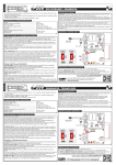
ENGLISH.
ELECTRONIC CIRCUITS
TL-28
16 CHANNELS R.F. EMITTER.
OPERATING MODE.
The R.F. Emitter TL-28, emit an signal till approximately 100 m. omnidirectional. This signal will be recognised and
executed exclusivity by Cebek R.F. receivers (TL-22, TL-23, TL-26 and TL-27).
Could to controller until 16 different channels.
It includes micro-switches to select the code, indicator Leds, 12 V battery and enclosure.
TECHNICAL CHARACTERISTICS.
Voltage. .................................................................................................
Minimum consumption (without emission). .........................................
Maximum Consumption, (emitting). .....................................................
Emission frequency. ..............................................................................
Maximum reach (approximately). ..........................................................
Protection against inversion polarity, (P.I.P.). ............................................
Antenna length. ....................................................................................
Sizes, (without antenna). .......................................................................
12 VDC Battery (type A23).
0 mA.
22,5 mA.
433,92 MHz.
100 m.
Yes.
148 mm.
125 x 67 x 31 mm.
you wish to connect at the same time various outputs, or if you wish to exclusively assign each push button to a one
channel, check the instruction manual of the receiver.
BATTERY SUBSTITUTION.
HOW TO OPEN THE ENCLOSURE AND SUBSTITUTE THE BATTERY. The TL-20 enclosure could be opened
pressing to the outside the removable enclosure cover. See the drawing.
With the front cover, removed from the rest of the enclosure, you could accede to the battery and micro-switches
battery. The new battery has to be identical than the previous one: 12 V and A23 type. When you will remove the old
battery you note that it is covered by a plastic cylindrical piece. Don't cast off it but place it on the new battery before
to place again it on the battery support; it's function is to correctly maintain both elements.
See and respect the indicated battery polarity and insert it carefully without forcing.
ANTENNA INSTALLATION.
ANTENNA INSTALLATION. The module requires an antenna to emit with the maximum power and efficiency. This
one is supplied with the module and it has to be installed before to emit.
The inferior part of the antenna includes a metallic piece with a screw. Place and screw it on the module basis,
reserved to this application. See Pic. 1. Do never use a tool to screw this union and avoid ant excessive pressure. The
pressure make by your finger will be enough to adjust both pieces.
The TL-28's antenna is made with flexible steel, nevertheless, don't fold the antenna, in right position. Don't use any
other antenna type, different than supplied one. If the supplied one will be damaged, contact your Cebek distributor
and ask for a new original. If you don't respect this point, the module doesn't properly work r and the module's
warranty will be cancelled.
Max. 45º
Pic. 1. Antenna Connection’s.
Trinary
Switches
Anntena
Extremity with Screw
Battery
Anntena Basis’s
OPERATING MODE.
ESPAÑOL.
ELECTRONIC CIRCUITS
TL-28
AÑOS
TO
TAL
YEARS
ANYS
3
WARRANTY
GARANTIA
Much more CEBEK module’s are aviable in our products range,
please, require our general catalogue or visit our Web side.
Http://www.cebek.com
GARANTIA
ANNÉ
All the module’s CEBEK have 3 years of total warranty
in thecnical repairing, and spares from the date of buy.
EMISOR R.F. de 16 CANALES.
El telemando emisor R.F. TL-28, realiza el envío de una señal codificada hasta un máximo de 100 m. omnidireccionales
aprox., que será reconocida y ejecutada exclusivamente por los receptores R.F. Cebek TL-22, TL-23, TL-26 y TL-27.
Admite el control de hasta 16 salidas distintas.
Incorpora microrruptores de selección de código, led indicador, pila de 12 V., y caja de uso.
CARACTERISTICAS TECNICAS.
Tensión de Alimentación. .....................................................................
Consumo mínimo, (sin emitir). .............................................................
Consumo máximo, (emitiendo). ..........................................................
Frecuencia de emisión. ........................................................................
Alcance máximo aproximado. .............................................................
Protección contra inversión de polaridad, (P.I.P.). ..................................
Longitud de la antena. ........................................................................
Medidas, (Sin antena). .........................................................................
TECHNICAL CONSULTATIONS.
If you have any doubt, you could contact your wholesaler or our Technical Department.
- E-Mail, [email protected] | Fax. 34.93.432.29.95 | by mail. P.O. Box. 23455 - 08080 Barcelona - Spain.
- Keep the invoice of this module. For any repair, the corresponding invoice had to be added. If the invoice is not
presented together wish this module, the module’s warranty will be automatically cancelled.
GARANTIE
SECURITY CODE. All Cebek Remote Control work with the regulated European Frequency 433,92 MHz. For this
reason, they includes a micro-switches battery composed by 8 trinary switches, allowing to configure a security code,
which make the difference and exclusivity of each module.
To adjust the micro-switches battery, firstly you have to remove the box screws and to separate the two parts. See
paragraph "Battery Substitution" to correctly do this operation.
Once the micro-switches battery discovered, you have to check the position of 8 switches, each one could be placed
in three different position : "-"; "0"; and "+". Change the original position (supplied form factory), moving and selecting
you own personal code, you will dispose of 13.122 possible combinations. Don't forget that the emitter's
configuration has to be the same than the receiver. If you don't insert the same code, the communication
between them will be impossible.
Once the code selected and all connection in the receiver done, you only have to press any push buttons and see
how the corresponding output is connected. The Led will intermittently light till you maintain pressed the push
button, to indicate that it is emitting. If the Led doesn't light, check the battery position, if the polarity is correct, or if it
is not discharged.
Don't press at the same time two or more push buttons, the emitter will only emit a single signal from on of them. If
Pila de 12 V. D.C. tipo A23.
0 mA.
22,5 mA.
433,92 MHz.
100 m.
Si.
148 mm.
125 x 67 x 31 mm.
FUNCIONAMIENTO.
canal específico, consulte las instrucciones del receptor.
CAMBIO DE LA PILA.
APERTURA DE LA CAJA Y CAMBIO DE LA PILA. La caja del TL-28 solamente puede ser abierta si previamente
desatornilla los cuatro puntos de sujeción situados en la parte posterior.
Empleando un destornillador fino de punta de estrella, y sin aplicar excesiva fuerza, extraigalos.
A continuación y como indica la ilustración, levante ligeramente la parte superior, aproximadamente un máximo de
45º, de lo contrario podría averiar distintas conexiones internas. Con ambos laterales separados podrá acceder a la
pila y a los microrruptores.
La nueva pila deberá ser idéntica a la anterior: 12 V., tipo A23. Observe y respete la polaridad indicada para la pila, e
introduzcala cuidadosamente, sin forzar el porta-pilas.
Finalmente vuelva a unir los dos laterales de la caja y proceda a la restitución de los cuatro tornillos de sujeción.
INSTALACION DE LA ANTENA.
INSTALACION DE LA ANTENA. El TL-28 precisa de una antena para poder emitir con el máximo de potencia y
eficacia. Esta se proporciona conjuntamente con el módulo, debiendo ser instalada antes de emitir.
El extremo inferior de la antena incorpora una pieza metálica con un tornillo. Encaje y enrosque dicho tornillo sobre la
base del módulo destinada a tal efecto. Observe la fig. 1. No utilice ninguna herramienta para apretar esta unión,
evite cualquier exceso de presión. Será suficiente la fuerza de sus dedos para el ajuste de ambas piezas.
La antena del TL-28 está constituida por acero flexible, no obstante, mantenga la varilla sin doblar, en posición recta.
No instale una antena distinta a la proporcionada con el módulo, si ésta sufriese algún percance, solicite el recambio
original a su distribuidor. Cebek no se hace responsable de la avería o del malfuncionamiento por el uso de antenas
ajenas.
Máx. 45º
Fig. 1. Conexión de la antena.
Batería de
Microrruptores
Antena
Extremo con tornillo
Pila
Base de Antena
FUNCIONAMIENTO.
CONSULTAS TECNICAS.
3
AÑOS
TO
TAL
YEARS
ANYS
CEBEK dispone de muchos más módulos distintos que pueden interesarle.
SOLICITE GRATUITAMENTE nuestro CATALOGO. O visite nuestra Web.
Http://www.cebek.com
GARANTIA
ANNÉ
Todos los módulos CEBEK gozan de 3 AÑOS de GARANTIA TOTAL
en mano de obra, y componentes a partir de la fecha de compra.
WARRANTY
GARANTIA
Para cualquier duda o consulta técnica dirijase a nuestro Dpto. Técnico.
- Por Fax. 93.432.29.95 | Por E-Mail, [email protected] | Correos. c/Quetzal, 17-21. (08014) BARCELONA.
- Conserve la factura de compra de este módulo. En una posible reparación deberá adjuntar una copia de ésta.
El no presentarla junto al módulo anulará automáticamente la garantía de 3 años del producto.
GARANTIE
CONFIGURACIÓN DEL CÓDIGO DE SEGURIDAD. Todos los telemandos Cebek trabajan en la frecuencia
homologada de 433,92 MHz. Por este motivo incorporan una batería de microrruptores compuesta por 8 switches
trinarios, que permitirá configurar un código de seguridad que diferencie y haga exclusivo cada módulo.
Para acceder a la batería de microrruptores, primero deberá desatornillar y extraer la parte posterior de la caja.
Observe el apartado Cambio De La Pila para realizar correctamente esta operación.
Una vez quede al descubierto la batería de microrruptores, comprobará la disponibilidad de 8 switches, cada uno de
los cuales podrá situar en tres posiciones distintas, "-"; "0"; y "+". Cambie la disposición que viene de fábrica
modificando los switches y escogiendo su código personal, dispondrá de 13.122 posibles combinaciones. Tenga en
cuenta que la combinación que realice en el emisor deberá ser la misma que posteriormente configure
sobre el receptor, de lo contrario no podrá establecerse la comunicación entre ambos.
Escogido el código, y realizadas todas las conexiones en el receptor, no tendrá más que presionar cualquiera de los
pulsadores y podrá observar como se conecta la salida correspondiente. El led parpadeará mientras mantenga
apretado un pulsador, indicando que se esta emitiendo. Si el led no se encendiese, compruebe que el sentido de la
pila corresponde a la polaridad correcta, o que ésta no se haya agotado.
No presione al mismo tiempo dos o más pulsadores, el emisor solo emitirá la señal de uno de ellos. Si desea conectar
al mismo tiempo varias salidas en el receptor, o si desea asignar exclusivamente cada uno de los dos pulsadores a un
Rev. Full0317