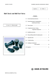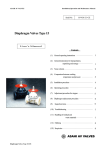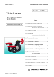
1
ASAHI AV VALVES
Installation,Operation and Maintenance Manual
Serial No.
H – V027 E – 4
Contents
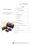
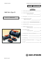
Ball Valve Type 21
(1)
General operating instructions
(2)
General instructions for transportation,
unpacking and storage
1
1
2
(3)
Name of parts
(4)
Comparison between working
User ’s Manual
temperature and pressure
3
(5)
Installation procedure
4
(6)
Operating procedure
9
(7)
Method of Adjusting face pressure
between ball and seat
(8)
(9)
9
Disassembling method
for parts replacement
10
Mounting actuator, metal Ensert and base(panel)
11
(10) Inspection items
13
(11) Troubleshooting
13
(12) Handling of residual and waste materials
13
(13) Inquiries
14
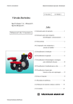
ASAHI AV VALVES
Ball Valve Type 21
0
ASAHI AV VALVES
Installation,Operation and Maintenance Manual
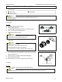
(1) General operating instructions
○ Operate the valve within the pressure Vs temperature range.
(The valve can be damaged by operating beyond the allowable range.)
○ Select a valve material that is compatible with the media, refer to “CHEMICAL RESISTANCE ON ASAHI AV
VALVE”.
(Some chemicals may damage incompatible valve materials.)
○ Do not use the valve to fluid containing slurry. (The valve will not operate properly.)
○ Do not use the valve on condition that fluid has crystallized.
(The valve will not operate properly.)
○ Do not step on the valve or apply excessive weight on valve. (It can be damaged.)
○ Do not exert excessive force in closing the valve.
○ Make sure to consult a waste treatment dealer to dispose of the valves.
(Poisonous gas is generated when the valve is burned improperly.)
○ Allow sufficient space for maintenance and inspection.
○ Keep the valve away from excessive heat or fire. (It can be deformed, or destroyed.)
○ The valve is not designed to bear any kind of external load. Never stand on or place anything heavy on the valve
at anytime.
○ Certain liquid such as H2O2, NaClO, etc may be prone to vaporization which may cause irregular pressure
increases, which may destroy the valve.
(2) General instructions for transportation, unpacking and storage
○ Keep the valve packed in the carton or box as delivered until installation.
○ Keep the valve away from any coal tar, creosote (antiseptic for wood), termite insecticide, vermicides, and
paint.
(This could cause swelling damage the valve.)
○ Do not impact or drop the valve. (It can be damaged.)
○ Avoid scratching the valve with any sharp object.
Ball Valve Type 21
1
ASAHI AV VALVES
Installation,Operation and Maintenance Manual
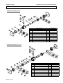
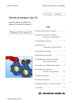
(3) Name of parts
Nominal size 15-50mm (1/2”-2”)
No.
1
◯
2
◯
3
◯
4b
◯
4c
◯
4d
◯
4e
◯
5
◯
6
◯
DESCRIPTION
Body
Ball
Carrier
End connector (Flanged end type)
End connector (Socket end type)
End connector (Threaded end type)
End connector(Spigot type)
Union nut
Stem
No.
7
◯
8
◯
9
◯
10
◯
11
◯
12
◯
13
◯
14
◯
DESCRIPTION
Seat
O-ring (A)
O-ring (B)
O-ring (C)
O-ring (D)
O-ring (E)
Stop ring
Handle
Nominal size 65-100mm (2 1/2”-4”)
No.
1
◯
2
◯
3
◯
4b
◯
4c
◯
4d
◯
4e
◯
5
◯
6
◯
Ball Valve Type 21
DESCRIPTION
Body
Ball
Carrier
End connector (Flanged end type)
End connector (Socket end type)
End connector (Threaded end type)
End connector(Spigot type)
Union nut
Stem
No.
7
◯
8
◯
9
◯
10
◯
11
◯
12
◯
13
◯
14
◯
15
◯
DESCRIPTION
Seat
O-ring (A)
O-ring (B)
Cushion
O-ring (C)
O-ring (D)
Stop ring
Handle
Screw
2
ASAHI AV VALVES
Installation,Operation and Maintenance Manual
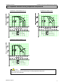
(4) Comparison between working temperature and pressure
Nominal size: 15mm-50mm (1/2”-2”)
Nominal size: 65mm (2 1/2”)
Nominal size: 80mm, 100mm (3”, 4”)
Caution
Do not operate the valve beyond the range of working temperature and pressure.
(The valve can be damaged.)
Ball Valve Type 21
3
ASAHI AV VALVES
Installation,Operation and Maintenance Manual
(5) Installation procedure
Flanged type (Material: PVC,C-PVC,PP,PVDF)
Necessary items
● Torque wrench
● Spanner wrench
● AV gasket
● Bolt, Nut, Washer (For many flanges specification)
(When a non-AV gasket is used, a different tightening torque specification should be followed.)
Procedure
5 flange assembly set was removed or loosen from body ◯
1 , O-ring (A) ◯
8
1) When the union nut ◯
should be installed into carrier and body groove. (In either horizontal or vertical installation, if necessary
apply a small amount of lubricant to O-ring to hold in place.) Align union nut and end connector with
the body. Insure end connector mates with body and O-ring. Make certain union nut threads onto body
smoothly. Tighten union nuts on each side valve until hand tight. Then using a strap wrench tighten
union nuts uniformly on each side approx 90o -180o turns, 1/4 to 1/2 turns.
2) Set the AV gasket between the flanges.
3) Insert washers and bolts from the pipe side, insert washers and nuts from the valve side, then
temporarily tighten them by hand.
Caution
The parallelism and axial misalignment of the flange surface should be under the values shown in the
following table to prevent damage the valve.
(A failure to observe them can cause destruction due to stress application to the pipe)
Unit : mm (inch)
Nom. Size
15-32mm
(1/2”-1 1/4”)
40-80mm
(1 1/2”-3”)
100mm
(4”)
Axial
Misalignment
Parallelism
(a-b)
1.0mm (0.04”)
0.5mm (0.02”)
1.0mm (0.04”)
0.8mm (0.03”)
1.0mm (0.04”)
1.0mm (0.04”)
(Axial misalignment)
(Parallelism)
4) Tighten the bolts and nuts gradually with a torque wrench to the specified torque level in a diagonal manner.
(Refer to fig.1.)
Recommended torque value
15-20mm
Nom. Size
(1/2”-3/4”)
17.5
Torque value
{179}
[155]
25-40mm
(1”-1 1/2”)
20.0
{204}
[177]
Unit: N-m{kgf-cm}[lb-inch]
Fig. 1
50, 65 mm
80, 100 mm
(2”, 2 1/2”)
(3”, 4”)
22.5
30.0
{230}
{306}
[230]
[266]
Caution
Avoid excessive tightening. (The valve can be damaged.)
Ball Valve Type 21
4
ASAHI AV VALVES
Installation,Operation and Maintenance Manual
Threaded type (Material : PVC,C-PVC,PP,PVDF)
Necessary items
● Sealing tape(A non-sealing tape can cause leakage.)
● Strap wrench(Do not use Pipe wrench.)
● Spanner wrench
Caution
Make sure that the threaded connections are plastic x plastic.
(Metallic thread can cause damage.)
Procedure
1) Wind a sealing tape around the external thread of joint, leaving the end (about 3mm) free.
5 with a strap wrench..
2) Loosen the union nut ◯
5 and the end connector ◯
4d .
3) Remove the union nut ◯
5 through the pipe.
4) Lead the union nut ◯
4d hardly with hand.
5) Tighten the external thread of the joint and the end connector ◯
4d by turning 180°-360°carefully without damaging it.
6) Using a spanner wrench, screw in the end connector ◯
Caution
Avoid excessive tightening. (The valve can be damaged.)
8 is mounted.
7) Make sure that the O-ring (A) ◯
4d and union nut ◯
5 directly on the body without allowing the O-ring (A) ◯
8 to come off.
8) Set the end connector ◯
5 on each valve until hand tight.
9) Tighten union nuts ◯
10) Using a strap wrench tighten union nuts uniformly on each on each side approx 90°-180°turns, 1/4 to
1/2 turns.
Caution
Avoid excessive tightening. (The valve can be damaged.)
Ball Valve Type 21
5
ASAHI AV VALVES
Socket type
Installation,Operation and Maintenance Manual
(Material : PVC, C-PVC)
Necessary items
● Adhesive for hard vinyl chloride pipes
● Strap wrench (Do not use the pipe wrench)
Caution
Do not install a socket type valve where the atmospheric temperature is 5℃ or lower.
(The valve can be damaged.)
Procedure
5 with a strap wrench.
1) Loosen the union nut ◯
5 and end connector ◯
4c .
2) Remove the union nut ◯
3) Lead the union nut through the pipe.
4c by wiping the waste cloth.
4) Clean the hub part of the end connector ◯
4c and the pipe spigot.
5) Apply adhesive evenly to the hub part of the end connector ◯
Caution
Do not apply more adhesives than necessary.
(The valve can be damaged due to solvent cracking.)
Adhesive quantity (guideline)
15mm 20mm
Nom. Size
(1/2”)
(3/4”)
1.0
1.3
Quantity(g)
25mm
(1”)
32mm
(1 1/4”)
40mm
(1 1/2”)
50mm
(2”)
65mm
(2 1/2”)
80mm
(3”)
100mm
(4”)
2.0
2.4
3.5
4.8
6.9
9.0
13.0
4c and leave it alone for at least 60
6) After applying adhesive, insert the pipe quickly to the end connector ◯
seconds.
7) Wipe away overflowing adhesive.
8 is mounted
8) Make sure that O-ring(A) ◯
4c and union nut ◯
5 directly on the body without allowing the O-ring (A) ◯
8 to come off.
9) Set the end connector ◯
5 hardly with hand.
10) Tighten union nut ◯
11) Using a strap wrench tighten union nuts uniformly on each side approx 90°-180°turns, 1/4 to 1/2 turns.
Caution
Avoid excessive tightening. (The valve can be damaged.)
Ball Valve Type 21
6
ASAHI AV VALVES
Installation,Operation and Maintenance Manual
Socket type (Material : PP, PVDF )
Necessary items
● Strap wrench (Do not use the pipe wrench.)
● Sleeve welder or automatic welding machine
● User’s manual for sleeve welder or automatic welding machine
Procedure
1)
2)
3)
4)
5)
6)
7)
8)
Loosen the union nut with a strap wrench.
5 and the end connector.
Remove the union nut ◯
5 through the pipe.
Lead the union nut ◯
For the next step, refer to the user’s manual for the sleeve welder or the automatic welding machine.
8 is mounted.
After welding, make sure that the O-ring (A) ◯
4c
5
8 to come off.
Set the end connector ◯ and the union nut ◯ directly without allowing the O-ring (A) ◯
5 hardly with hand.
Tighten union nut ◯
Using a strap wrench tighten union nuts uniformly on each side approx 90°-180°turns, 1/4 to 1/2 turns.
Caution
Avoid excessive tightening. (The valve can be damaged.)
Spigot type (Material : PVDF )
Necessary items
● Strap wrench (Do not use the pipe wrench.)
● Automatic welding machine
● User’s manual for automatic welding machine
Procedure
1)
2)
3)
4)
5)
6)
7)
8)
Loosen the union nut with a strap wrench.
5 and the end connector.
Remove the union nut ◯
5 through the pipe.
Lead the union nut ◯
For the next step, refer to the user’s manual for the sleeve welder or the automatic welding machine.
8 is mounted.
After welding, make sure that the O-ring (A) ◯
4e and the union nut ◯
5 directly without allowing the O-ring (A) ◯
8 to come off.
Set the end connector ◯
5 hardly with hand.
Tighten union nut ◯
Using a strap wrench tighten union nuts uniformly on each side approx 90°-180°turns, 1/4 to 1/2 turns.
Caution
Avoid excessive tightening. (The valve can be damaged.)
Ball Valve Type 21
7
ASAHI AV VALVES
Installation,Operation and Maintenance Manual
Caution
{15mm-50mm(1/2”-2”)}
It is recommended to install the valve with the threaded carrier to the upstream side of the system.
This allows for an increase safety factor and eliminating a threaded connection when used as a blocking valve.
This also allows the down stream union nut and end connector to be removed safely under pressure.
It increases the safety where there is no chance of thread leakage or accidentally removing the carrier.
The designation of the up stream side (non threaded carrier is marked as shown) on the body.
Nominal size 15mm - 50mm (1/2” – 2”)
Ball Valve Type 21
8
ASAHI AV VALVES
Installation,Operation and Maintenance Manual
(6) Operating Procedure
Caution
Avoid excessive tightening. (The valve can be damaged.)
○ Turn the handle gently to open or close.
(Turn the handle clockwise to close and counter clockwise to open.)
Fully closed …… The position of the handle should be perpendicular to the pipe.
Fully opened …… The position of the handle should be parallel to the pipe.
Fully opened
Fully closed
(7) Method of Adjusting Face Pressure between Ball and Seat
Necessary items
● Strap wrench
● Protective gloves
●Safety goggles
●Screwdriver (+) (only with nominal size 65~100mm)
Procedure
1) Completely discharge fluid from pipes.
2) Turn the handle to full close.
5 with a strap wrench.
3) Loosen the right union nut and the left one ◯
4) Remove the body part from piping system.
Caution
Wear protective gloves and safety goggles as some fluid remains in
the valve. (You may be injured.)
5)
Pull the handle off the body part.
Caution
15
As for nominal size 65-100mm (2 1/2”-4”), loosen the screw ◯
properly with a screwdriver before pulling it off..
6)
Engage the upper convex part of the handle with the concave part of
3 .
the union ◯
Caution
As for nominal size 15-50mm
3 on the right side when viewed from the
Only the union ◯
trademark (AV mark) can be adjusted.
As for nominal size 65-100mm
adjust the unions on both sides.
7)
8)
9)
Make an adjustment by turning the union clockwise (to tighten it)
or counter clockwise (to loosen it).
Make sure that the handle can be operated smoothly.
Assemble the valve by following the above procedure in the reverse
order, starting at 6)
Ball Valve Type 21
9
ASAHI AV VALVES
Installation,Operation and Maintenance Manual
(8) Disassembling Method for Replacing Parts
Necessary items
● Strap wrench
● Protective gloves
●Safety goggles
Caution
Wear protective gloves and safety goggles as some fluid remains in the valve.
(You may be injured.)
<Disassembly>
Procedure
1) Completely discharge fluid from pipes.
2) Turn the handle to full close.
5 with a strap wrench.
3) Loosen the right union nut and the left one ◯
4) Remove the body part from piping system.
5) Pull the handle off the body part.
Caution
15
As for nominal size 65-100mm (2 1/2”-4”), loosen the screw ◯
properly with a screwdriver before pulling it off..
6)
Engage the upper convex part of the handle with the concave part
of the union.
Caution
As for nominal size 15-50mm
3 on the right side when viewed
Only the union ◯
from the trademark (AV mark) can be adjusted.
As for nominal size 65-100mm, adjust the unions on both sides.
14 counter clockwise to loosen it
In the engaged state, turn the handle ◯
3 .
and remove the union ◯
7
8) Remove the seat ◯ carefully by hand without damaging it.
2 by hand.
9) Push out the ball ◯
6 from the top flange side to the body side.
10) Push out the stem ◯
7)
<Assembly>
Procedure
Carry out the assembly work in the reverse procedure from item 10)
Caution
7 on the valve, check the seat for its face and back.
With regard to item 8), before installing seat ◯
Ball Valve Type 21
10
ASAHI AV VALVES
Installation,Operation and Maintenance Manual
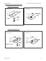
(9) Mounting actuator, Ensat and base (panel)
○ Attach actuator to the top flange
Procedure
14 .
1) Remove the handle ◯
Caution
15
As for nominal 65mm-100mm, tighten the screw ◯
properly before removing it.
2)
24 to actuator ◯
23 with bolt (A).
Fix the stand ◯
3)
6 to the joint ◯
25 with screw (B) ◯
28 .
Fix the stem ◯
4)
25 with actuator ◯
23 .
Engage the joint ◯
5)
24 to the top flange
Fix the stand ◯
27 .
with bolt-nut (B) ◯
6)
23 by hand.
Make sure that the valve works smoothly, by operating actuator ◯
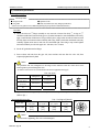
○ Attach Inserted metal to the bottom stand.
Nominal 15-50mm(1/2”-2”)
Bottom stand
Procedure
Refer to the user’s manual for the Inserted metal
(Commercially available.)
Bottom stand dimension
S1
(1/2”)
19
(3/4”)
19
(1”)
19
(1 1/4”)
30
(1 1/2”)
30
(2”)
30
(2 1/2”)
48
(3”)
55
(4”)
65
65~100mm>
Nom.Size
15mm
20mm
25mm
32mm
40mm
50mm
65mm
80mm
100mm
<Nominal size
Ball Valve Type 21
S2
7.3
7.3
7.3
9
9
9
9
11
11
Unit; mm
S3
11
11
11
15
15
15
6
7
8
Nominal 65-100mm (2 1/2”- 4”)
Bottom stand
11
ASAHI AV VALVES
Installation,Operation and Maintenance Manual
○Fixation of bottom stand with panel
Nominal size: 15mm-50mm (1/2”-2”)
Before the fixation
After the fixation
Nominal size: 65mm-100mm (2 1/2”-4”)
Before the fixation
Ball Valve Type 21
After the fixation
12
ASAHI AV VALVES
Installation,Operation and Maintenance Manual
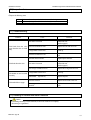
(10) Inspection items
○Inspect the following items.
(1)
(2)
(3)
Existence of scratches, cracks, deformation, and discoloring.
Existence of leakage from the valve to the outside.
Existence of leakage when the valve is opened fully at right or left.
(11) Troubleshooting
Problem
Cause
The carrier is loosened.
Fluid leaks from the valve The seat is scratched or worn.
even when the valve is closed
fully.
Foreign matter is in the valve.
Fluid leaks from the valve.
The handle can not be turned
smoothly.
The handle fails to engage.
Treatment
Adjust the face pressure between the
ball and the seat.
(Refer to page 9)
Replace the seat with a new one.
Clean up.
The ball is scratched or worn.
Replace the scratched ball with a new
one.
The union nut is loosened.
Tighten up the union nut.
The carrier is loosened.
Adjust the face pressure between the
ball and the seat.
(Refer to page 9)
The O-ring is scratched or worn.
Replace the O-ring with a new one.
Foreign matter is in the valve.
Clean up.
Deformation. (By heat etc.)
Replace the parts.
The stem is broken.
Replace the stem with a new one.
The engagement between the stem and the ball Replace the stem and ball with new
is broken.
ones.
(12) Handling of residual and waste materials
Caution
In discarding remaining or waste materials, be sure to ask waste service company.
(Poisonous gas is generated.)
Ball Valve Type 21
13
ASAHI AV VALVES
Installation,Operation and Maintenance Manual
(13) Inquiries
ASAHI ORGANIC CHEMICALS INDUSTRY CO., LTD.
Nobeoka Head Office
: 2-5955, Nakanose- Cho, Nobeoka –City, Miyazaki- Pref. , Japan.
Tel : (81) 982-35-0880 Fax : (81) 982-35-9350
Tokyo Head Office
: (Furukawachiyoda Bldg.) 15-9, Uchikanda 2- Chome, Chiyoda-Ku, Tokyo, Japan.
Tel : (81) 3-3254-8177 Fax : (81) 3-3254-3474
Singapore Branch Office
: 16 Raffles Quay, #40-03 Hong Leong Building, Singapore 048581.
Tel : (65) 220-4022 Fax : (65) 324-6151
Europe Representative Office : Kaiser-Friedrich-Promenade 61 D-61348 Bad Homburg v. d. H. Germany.
Tel : (49) 6172-9175-0 Fax : (49) 6172-9175-25
Shanghai Branch Office
ASAHI /AMERICA Inc.
: Room 1301-P Shanghai Kerry Center, 1515 Nanjing Xi Road, Shanghai China
Tel : (21) 5298-6900 Fax : (21) 5298-6556
:35 Green Street P.O.Box 653 , Malden, Massachusetts 02148 U.S.A.
Tel : (1) 781-321-5409 Fax : (1) 781-321-4421
Distributor
Ball Valve Type 21
14
ASAHI AV VALVES
Installation,Operation and Maintenance Manual
Ball Valves Type 21
ASAHI AV VALVES
Information in this manual is subject to change without notice.
Ball Valve Type 21
2002. 11
15