1
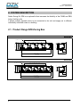
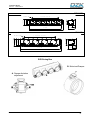
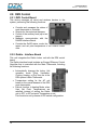
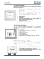
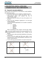
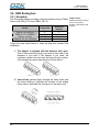
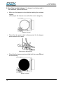
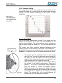
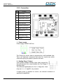
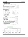
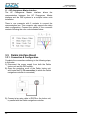
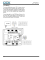
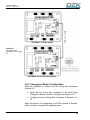
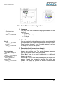
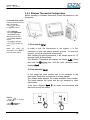
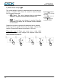
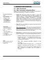
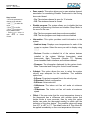
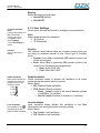
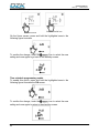
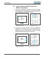
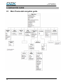
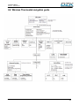
Installation Manual Table of contents Page 1. WARNINGS, ENVIRONMENTAL POLICY, AND CERTIFICATIONS ................................................ 5 1.1. Warnings.................................................................................................................................... 5 1.2. Environmental Policy ................................................................................................................. 5 1.3. FCC Regulatory Notices ............................................................................................................ 6 1.4. INTERTEK / UL Regulatory Notices .......................................................................................... 7 2. SYSTEM DESCRIPTION ................................................................................................................... 8 2.1. Product Range DZK Zoning Box................................................................................................ 8 2.2. DZK Control ............................................................................................................................. 10 2.2.1. DZK Control Board............................................................................................................ 10 2.2.2. Daikin - Interface Board .................................................................................................... 10 2.2.3. Main Thermostat ............................................................................................................... 11 2.2.4. Wireless Thermostat ......................................................................................................... 11 2.2.5. Heat Pump Changeover Master ....................................................................................... 11 3. DESCRIPTION, INSTALLATION AND CONNECTION OF THE COMPONENTS ........................... 12 3.1. General recommendations....................................................................................................... 12 3.2. DZK Zoning box ....................................................................................................................... 14 3.2.1. Assembly .......................................................................................................................... 14 3.2.2. Damper setting.................................................................................................................. 17 3.2.3. Connection........................................................................................................................ 19 3.3. Daikin Interface Board ............................................................................................................. 22 3.3.1. Connection & Configuration .............................................................................................. 22 3.4. Heat Pump Changeover Master ................................................................................................ 23 3.4.1. Installation......................................................................................................................... 23 3.4.2. Wiring................................................................................................................................ 24 3.4.3. Changeover Master Configuration .................................................................................... 25 3.5. Main Thermostat ...................................................................................................................... 26 3.5.1. Installation......................................................................................................................... 26 3.5.2. Wiring................................................................................................................................ 26 3.5.3. Main Thermostat Configuration......................................................................................... 27 3.6. Wireless Thermostat ................................................................................................................ 28 3.6.1. Installation......................................................................................................................... 28 3.6.2. Wireless Thermostat Configuration................................................................................... 29 4. ADVANCE CONFIGURATION ......................................................................................................... 31 4.1. Main Thermostat ...................................................................................................................... 31 4.1.1. Main Thermostat Configuration Menu............................................................................... 31 4.1.2. Interface Menu .................................................................................................................. 36 4.1.3. User Settings .................................................................................................................... 37 4.2. Wireless Thermostat ................................................................................................................ 38 4.2.1. Access to the Configuration Menu .................................................................................... 38 4.2.2. Configuration Menu........................................................................................................... 38 4.2.3. User Settings .................................................................................................................... 41 5. COMMISSIONING STEPS ............................................................................................................... 43 5.1. Turn on power to all systems................................................................................................... 43 5.2. Communications with the Indoor unit – Modes / Temperature ................................................ 45 5.3. Zone assignment ..................................................................................................................... 46 5.4. Q-Adapt level selection ............................................................................................................ 46 5.5. Other configuration parameters ............................................................................................... 48 6. EXCEPTION CODES ......................................................................................................................... 49 7. AUTO DIAGNOSTICS ...................................................................................................................... 50 7.1. Zoning box control board ......................................................................................................... 50 7.2. Daikin Interface Board ............................................................................................................. 51 8. NAVIGATION GUIDE ....................................................................................................................... 52 8.1. Main Thermostat navigation guide........................................................................................... 52 8.2. Wireless Thermostat navigation guide..................................................................................... 53 9. TROUBLESHOOTING...................................................................................................................... 55 Installation Manual Rev1.03 Date 09-2014 1. WARNINGS, ENVIRONMENTAL POLICY, AND CERTIFICATIONS 1.1. Warnings For personal safety and equipment protection, follow these instructions: Do not operate the system if it is wet, or handle it with wet hands. Connect the power supply cable before connecting the AC power. Perform any connection or disconnection with the power supply OFF. Verify that there is no short-circuited connection in the connectors between different cables or ground. Verify there are no abnormalities in the wiring. 1.2. Environmental Policy Never dispose of this equipment with household waste. Electrical and electronic products contain substances that can be harmful to the environment if they are not given proper treatment. The symbol of the crossed container indicates separate collection of electronic equipment, unlike the rest of urban garbage. For proper environmental management, the equipment to be disposed must be taken to the proper collection center at the end of its lifespan. The components of this equipment can be recycled. Follow the existing regulations on environmental protection in your area. The unit must be delivered to your dealer if it is being replaced. If it is to be discarded, it must be sent to a specialized collection center. 5 Installation Manual Rev1.03 Date 09-2014 1.3. FCC Regulatory Notices Modification statement Corporación Empresarial Altra S.L. has not approved any changes or modifications to this device by the user. Any changes or modifications could void the user’s authority to operate the equipment. Interference statement This device complies with Part 15 of the FCC Rules. Operation is subject to the following two conditions: (1) this device may not cause interference, and (2) this device must accept any interference, including interference that may cause undesired operation of the device. Radiation Exposure Statement This device complies with FCC radiation exposure limits set forth for an uncontrolled environment and meets the FCC radio frequency (RF) Exposure Guidelines in Supplement C to OET65 This transmitter must not be co-located or operating in conjunction with any other antenna or transmitter. FCC Class B digital device notice This equipment has been tested and found to comply with the limits for a Class B digital device, pursuant to part 15 of the FCC Rules. These limits are designed to provide reasonable protection against harmful interference in a residential installation. This equipment generates uses and can radiate radio frequency energy and, if not installed and used in accordance with the instructions, may cause harmful interference to radio communications. However, there is no guarantee that interference will not occur in a particular installation. If this equipment does cause harmful interference to radio or television reception, which can be determined by turning the equipment off and on, the user is encouraged to try to correct the interference by one or more of the following measures: Reorient or relocate the receiving antenna. Increase the separation between the equipment and receiver. Connect the equipment into an outlet on a circuit different from that to which the receiver is connected. Consult the dealer or an experienced radio/TV technician for help. 6 Installation Manual Rev1.03 Date 09-2014 1.4. INTERTEK / UL Regulatory Notices The units shall be tested by a Nationally Recognized Testing Laboratory (NRTL) in accordance with ANSI/UL Standard UL 1995/CAN/CSA-C22.2 No. 236-11 – 4th Edition (R2011) – Heating and Cooling Equipment, and will bear the Listed Mark. All wiring shall be in accordance with the National Electric Code (NEC)/Canadian Electrical Code (CEC). 7 Installation Manual Rev1.03 Date 09-2014 2. SYSTEM DESCRIPTION Daikin Zoning Kit, DZK is an optional kit that increases the flexibility of the FXMQ and FBQ Indoor Unit fan coils. It allows multiple separate ducts to be connected to fan coil and supply air to different individually controlled zones in a building. 2.1. Product Range DZK Zoning Box DZK030E5 O 7-11/16 9-5/8 5 X 5-7/8= 29-1/2 9-5/16 10-7/16 12- O1/4 hole 4-5/8 41-5/16 10-7/16 43-9/16 DZK030E4 O 5-11/16 5 X 5-7/8= 29-1/2 9-5/16 9-5/8 10-1/4 12- O 1/4 hole 4-5/8 41-5/16 43-9/16 8 10-7/16 Installation Manual Rev1.03 Date 09-2014 DZK048E6 7 X 5-7/8= 41-5/16 O 5-11/16 9-5/8 9-5/16 10-7/16 16-O1/4 hole 4-5/8 10-7/16 51-3/16 53-7/16 DZK048E4 7-11/16 O 9-5/8 7 X 5-7/8= 41-5/16 9-5/16 10-7/16 16- O 1/4 hole 4-5/8 10-7/16 51-3/16 53-7/16 DZK Zoning Box B. Motorized Damper A. Damper limitation adjustment B A 9 Installation Manual Rev1.03 Date 09-2014 2.2. DZK Control 2.2.1. DZK Control Board This device manages all wired and wireless devices in the system, performing the following functions: Controls and manages the status of each thermostat or controller. Outputs for the motorized dampers. Control of the auxiliary heat (up to two stages). Manages communication with the DAIKIN Interface Board. Controls the On/Off status, mode, fan speed, and set point temperature of the DAIKIN Indoor units. 2.2.2. Daikin - Interface Board This unit integrates the Daikin Indoor unit with the DZK control board. The Daikin interface board includes an Energy Efficiency Control Algorithm that is controlled with the Main Thermostat, including the following functions: Automatically changes the Indoor Unit operation mode (Stop, Ventilation, Cooling, Heating, or Dry) from the in the DZK system’s Main Thermostat. Temperature setting for the AC unit based on the overall demand of the DZK zone thermostats. Defrost function: In heating Mode, when User Set Point Temperatures are satisfied, instead of setting the Daikin unit to OFF, a 60F set point Temperature is set. This function is set by means of DIP-switch configuration. 10 Installation Manual Rev1.03 Date 09-2014 2.2.3. Main Thermostat Graphic color touch pad display for control of zone temperature master thermostat. Wall mounted. Graphic interface with 3 languages (Spanish, English, and French). Zone On/Off. Set point temperature setting (steps of 1ºF). When configured as master, operation mode selection for the system (STOP, COOL, HEAT, AUTO CHANGEOVER EMERGENCY HEAT, DRY). Sleep Function. Eco-Adapt. Time schedule programming and, when configured as master, operation mode scheduling. Remote zone control. Used to set system parameters. 2.2.4. Wireless Thermostat This is a monochrome temperature. battery powered, wall-mounted, and back-lighted LCD touchpad digital thermostat to control the zone Zone On/Off. Set point temperature setting at steps of 1 ºF. Sleep Function. Remote zone access. Local ventilation. Time schedule control. Powered by two 1,5V batteries (type AAA; included). 2.2.5. Heat Pump Changeover Master Mode synchronization module for VRV Heat Pump installations with multiple indoor units. Power Connection to be wired from RS485 MODBUS interface included in the Zoning Box control Board. To be mounted on damper number #1 in the Zoning Box. Synchronization module for Heat Pump installations with multiple indoor units with DZK Zoning box. Heat Pump Changeover Master controls up to 16 DZK systems in the same VRV system. 11 Installation Manual Rev1.03 Date 09-2014 3. DESCRIPTION, INSTALLATION AND CONNECTION OF THE COMPONENTS 3.1. General recommendations Closely follow the instructions on this manual to avoid installation and maintenance issues. The system should only be installed by qualified personnel. Never use solid wire to install the system. This is a communication device and requires the use of communication cables. While connecting the devices, be sure the system is not powered. Follow the local installation regulations for low and high voltage installation. The recommended specifications for the cable to install this system are: o 4 wired o Stranded o AWG 20 o Plenum o Shielded When connecting to other systems fed with high voltage, only use the A and B contacts of the communication bus. It is not recommended to connect the + and – contacts, nor the ground. Follow the color codes and polarity indications in the system components. Do not run the bus cable near high power cables or near electrical motors to avoid electromagnetic interference in the system communications. Use the following recommendations to locate the thermostat: h= 5 ft 12 Installation Manual Rev1.03 Date 09-2014 To open the thermostat in preparation for its installation, it is recommended to use a coin. Using a screwdriver of other Sharp tool can damage the frame and the electronic components of the thermostat. If upon receiving the unit it is determined that one of the outlets will not be used, take the following actions: 1) Install the unit and wiring ready to start with the Main Thermostat Configuration. The unit should have all dampers open. 2) Configure the Main Thermostat. Once the thermostat is assigned a zone, all other dampers will close with the exception of that assigned to the Master thermostat. 3) At this time, disconnect the motor cable from the outlet that will not be used. 4) Permanently seal the outlet using the supplied plug and follow the local installation recommendations. 13 Installation Manual Rev1.03 Date 09-2014 3.2. DZK Zoning box 3.2.1. Assembly The Zoning Box allows providing a fast and simple zoning to Daikin Keep in mind Make sure that the zoning indoor units FBQ_PVJU and FMXQ_PAVJU. box is in its correct Models Damper Size Number of Dampers FBQ 18 - 24 - 32 PVJU FXMQ 14 - 18 – 24 PAVJU 6” 8” 6” 8” 5 4 6 4 FBQ 36 - 48 PVJU FXMQ 30 - 36 - 48 - 54 PAVJU Follow the steps listed below to make an easy and reliable DZK installation: 1. The adaptor is shipped with the dampers fully open. One of them includes a plug to be used in case one of the dampers is not used. If the damper is not used, the contractor needs to be sure that the plug will stay in place. If all dampers are used, take the plug out and store it. 2. Insert sharp pointed object through the frame holes and the frame sealing to facilitate the location of the setting holes used to assemble the zoning box to the indoor unit. 14 position. (Actuators at the bottom) Installation Manual Rev1.03 Date 09-2014 3. Take away the indoor unit collar. Insert a screw (not fully tightened) in the bottom corners of the indoor unit as how in the following figure: 4. Sit the zoning box on the screws as shown below, and then affix the box using the left screws. 5. Attach each zone duct with its assigned damper. Follow the local recommendations to insulate and seal the ductwork with the damper. Make a cutout along the duct to keep the motor outside of the insulation. 15 Installation Manual Rev1.03 Date 09-2014 6. Use of the insulated stopper. If a damper is not being used in the installation, proceed as follows: Make sure the damper is closed before installing the insulated stopper. (The damper will close as soon as the first zone is assigned.) Damper is closed Check that the power cable is disconnected for the damper motor that will not be used. Power cable is disconnected Check that the damper remains airtight with the power ON and the fan running. Damper is closed 16 Installation Manual Rev1.03 Date 09-2014 3.2.2. Damper setting The dampers included in the zoning box has a built-in control system that allows you to manually set the maximum and minimum opening of each damper according to the needs of each installation. Keep in mind This setting must be done after all dampers are assigned to their thermostats. REG lever Average Flow (REG) Due to the unique characteristics of each ID unit supply port with respect to the dampers of the box, the flow distribution is not identical in each damper. The central dampers receive more airflow than the others, being the damper No. 1 the one that receives less flow. This zoning box offers maximum aperture adjustment which balances the flow of each damper to the needs of the installation. By default, the dampers are configured with a maximum opening at Position I. To adjust the control of the dampers proceed as follows: Average flow adjustment lever The damper must be completely closed to mechanically adjust its flow. To make this adjustment create demand in all zones, so that the indoor unit runs at maximum capacity. Then deactivate the zone to be adjusted, and verify that there is no air supplied to that zone. With the damper closed, place the lever marked REG in the actuator to the desired open position. There are 4 position - I, II, III, and IV, with position I being completely open and position IV having the slightest opening. Perform the setting of the dampers by changing the lever REG position, beginning with the central one and ending with damper No. 1 (Closest to the zoning box control board). The reduced flow in the central dampers will increase the flow of the dampers at the ends. 17 Installation Manual Rev1.03 Date 09-2014 Using an anemometer verify that the flow in each grille is within the installation requirements. Minimum Air (A-M) Similarly, the zoning box allows a minimum air opening for each damper, if needed. By default, the “a” damper is configured in the full-close position. To adjust minimum air for any damper, proceed as follows: 18 Check that the dampers are wide open to start its control. To do so, set the system to STOP mode, from the Main Thermostat. Perform the setting of the dampers by changing the lever A-M position beginning with the one in the centre of the box and ending with damper 1. (Closest to the zoning box control board). Reduced flow in the central dampers will increase the flow of the dampers at the ends. With the damper open, place the handle A-M in the desired open position. It has 4 positions - a, b, c, d-, where "a" is fully closed and is "d" is the fully open. Check with an anemometer that the flow in each grille is within the installation requirements. A-M lever Minimum air adjustment lever Installation Manual Rev1.03 Date 09-2014 3.2.3. Connection Ref Function 1 Power supply 2 Heating Stage 1 Output 3 Heating Stage 2 Output 4 Protection probe input 5 Alarm input (NC) 6 Actuator Control output 7 Daikin Interface Board 8 Expansion bus 9 Wireless Interface 10 Reset System Button 11 HP Changeover Master interface 1. - Power supply Power supply 120/240 VAC line. The Zoning box control board is protected by a self-resettable fuse. This is an electronic component that does not require any action other than cycling the power to perform the reset. 2. - Heating Stage 1 Output If the system includes Auxiliary Heat, when required by the heat demand, this output enables the First Stage of Auxiliary Heat. The technical specifications for the 1st Stage Aux. Heat relay are: Imax. =1 A @ 24V, dry contacts. If higher power is required for control, use external contactors of appropriate capabilities. 19 Installation Manual Rev1.03 Date 09-2014 3. - Heating Stage 2 Output This output enables Second Stage of Auxiliary Heat, if the system includes two stages Auxiliary Heat. The technical specifications for the 2nd Stage Aux. Heat relay are: Imax. =1 A @ 24V, dry contacts. If higher power is required for control, use external contactors with appropriate capabilities. 4. - Protection probe Input This input is used to connect the supply temperature sensor. 5. - Alarm input (NC) When this input is open it will stop the AC unit, and close all dampers. This input is shipped with a jumper in the connector that should be left in place unless an alarm input is connected. 6. - Actuator control outputs These outputs are used to drive the damper actuators with 12VDC control for each damper, as shown in the following diagram: 20 Installation Manual Rev1.03 Date 09-2014 7. - Daikin Interface Board This Interface provides the communication between Zoning box control board and Daikin Indoor unit. 8. - Expansion Bus The expansion bus allows the connection of the Main Thermostat. There are 3 connectors with 5 contacts available to connect the expansion Bus. The Main Thermostat is connected to this bus. Connect the cables to the connector contacts according with the color code indicated below. 9. - Wireless Interface This device provides the communication between the Zoning box control board and the Wireless thermostats. Keep in mind Once this sequence is started it cannot be interrupted and the Quick Setup process should be allowed to finish. 10. - Reset System Button If the whole system needs to be reset (normally a replacement board that has been used before, or at the request of the technical support as a last resource to fix a problem), press and hold SW1 until LED 19 stops flashing. A system reset will return all configurations to default values and conditions. 21 Installation Manual Rev1.03 Date 09-2014 11. – HP changeover Master interface The HP Changeover Master interface allows the communication between the HP Changeover Master interface and the DZK systems in a multiple indoor units installation. There is one connector with 5 contacts to connect the communication bus. This connector only supports the daisy chain configuration. Connect the cables to the connector contacts following the color code indicated below. 3.3. Daikin Interface Board 3.3.1. Connection & Configuration Complete the connections adhering to the following steps, in this order: 1) Disconnect the power supply from both the Daikin Indoor unit and the DZK system. 2) Open the protective cover of the Daikin Indoor unit, and locate the P1, P2 connection (to which the Daikin navigation controller is connected). 3) Connect a two-wire cable to P1 P2 on the Indoor unit, in parallel with the Daikin navigation controller. 22 Installation Manual Rev1.03 Date 09-2014 Connect the other end of this cable to the connector labeled P1 P2 on the interface unit mounted on top of the control board, maintaining the polarity. DIP switches Configuration 2 Speeds Default configuration 3 Speeds 4) Close the Daikin Indoor unit’s protective cover. 5) Configure the DIP-switch as required. 3.4. Heat Pump Changeover Master System ID To configure this parameter, see on page 31. 3.4.1. Installation Heat Pump Changeover Master is a synchronization module for VRV Heat pump installations with multiple indoor units with DZK Zoning box (for VRV Heat recovery is not necessary). The operation mode is set by the DZK master system (System ID: 1) to the rest DZK systems. Heat Pump Changeover Master controls up to 16 DZK systems. The DZK Master system (System ID: 1) must be connected to the Indoor unit with the remote control configured as the system Master. Install the module on the damper #1 of the DZK master system as shown in the following pictures. 23 Installation Manual Rev1.03 Date 09-2014 3.4.2. Wiring The wiring should not exceed 130 ft. between device and stranded AWG20 shielded cable should be used. Connect the Heat Pump Changeover Master module with the RS485 MODBUS interface on the DZK Master system. Use a 4 wire shielded cable, stranded, and plenum. Connect the cable from the DZK Master System to the rest of the DZK Zoning systems to be controlled by the Heat Pump Changeover Master module. Connect only the communication wires A & B contacts. DZK-CM-1 AWG 20 – 4 wired *SYSTEM ID: 1> Master System 24 *SYSTEM ID: 1> Master System AWG 20 – 2 wired Installation Manual Rev1.03 Date 09-2014 System ID To configure this parameter, see on page 31. *SYSTEM ID: 2 to 16> Secondary System 3.4.3. Changeover Master Configuration Once the installation is finished and the Zoning Box configured (System ID): Verify that the Zoning Box connected to the Heat Pump Changeover Master module is configured as System ID: 1. Configure the other Zoning Box as System ID between 2 to 16. When the System ID configuration in all DZK systems is finished, wait 5 minutes to complete the update process. 25 Installation Manual Rev1.03 Date 09-2014 3.5. Main Thermostat 3.5.1. Installation The Main Thermostat is available for wall mount. The wiring should not exceed 130 ft, and stranded AWG20 shielded cable should be used. To mount the thermostat on the wall, take the following steps: Disassemble the thermostat in three parts. To split the frame from the base, use the edge of a coin. Do not use any sharp object. Affix the wall plate to the wall using screws and anchors according with the wall material. Insert the cable to the middle plate, and reassemble it to the wall plate. Reassemble the front frame to the base. 3.5.2. Wiring DZK thermostats are connected to the expansion bus. The wall mounted thermostats are wired to the screws located in the middle frame. Be sure to connect the cables according to the engraving in the middle frame. 26 Installation Manual Rev1.03 Date 09-2014 3.5.3. Main Thermostat Configuration Language -Press the value to select. to confirm the -Press value. Zone ID to change -Press the value. -Press to confirm the value. Zone subordinate - Press NO to change the value. to change the - Press subordinate zone. - Press to return to previous menu. - Press to confirm the value. 1) Language You may select one of the three languages available for the interface. Español English (Default) Français 2) Select Zone It is now required to define the zone number associated with this thermostat. Each zone is associated with a control outlet. Zone 1 controls damper 1, zone 2 controls damper 2, and so on for up to 6 zones in the system. 3) Zone subordinate (subordinate damper) If needed, the system allows associating more than one damper with a single zone. This allows managing dampers from the thermostat that is being configured. Select No if there is no need to associate an additional damper with a zone. Select Link if one or more additional dampers are needed for a zone. Repeat this process to associate the outlets as needed. The screen will indicate the number of subordinate dampers associated with the zone. 27 Installation Manual Rev1.03 Date 09-2014 Thermostat type Each DZK system must have one Main Thermostat configured as Master. The thermostat’s capabilities are determined by how it is configured: Master thermostat: Controls the system and zone parameters, operation mode, Time schedule programming, and AC configuration. Zone thermostat: Controls the local temperature and activation/deactivation of scheduled temperatures, and local ventilation. Thermostat Type to change - Press the value. - Press to confirm the value. Given that only one thermostat can be configured as Master, this parameter will not appear for selection if one thermostat in the system was already configured as Master. Thermostat reset: If there was some error in the initial configuration process and it is required to make changes, follow the steps described on page 27. 3.6. Wireless Thermostat 3.6.1. Installation Wireless thermostats are only available for wall mount. The maximum reach between the Zoning box control board and the wireless thermostat in clear line of sight is 164 ft (50m). To mount the thermostat on the wall, take the following steps: 28 Disassemble the thermostat in three parts as shown in the following figures. To split the frame from the base, use the edge of a coin. Do not use any sharp object. Affix the wall plate to the wall using screws and anchors according with the wall material. Reassemble the front frame to the base as shown in the following figure: Important Perform the pairing of thermostat in their final location. Distances less than 18 inches between the thermostat and the control board can saturate the receivers and make the pairing impossible. Installation Manual Rev1.03 Date 09-2014 3.6.2. Wireless Thermostat Configuration Before installing a Wireless thermostat, install the batteries in the thermostat. To activate Zone search From the Home Screen of Main Thermostat: to access - Press Configuration menu. - Press Settings. - Press Configuration. - Press Enter on the advertisement screen. - Press Zone search to access. - Press On to activate. to confirm the - Press value. When you finish the association, turn it OFF to close the zone search. 1) Zone search In order to pair the thermostats in the system, it is first necessary to open the pairing protocol process. To open this protocol, you must activate the zone search. After initiating the pairing sequence, it will remain active for 15 minutes to pair all thermostats. The Wireless Thermostat will display the letters . Press and hold the icon until the zone selection menu displays . 2) Zone selection In this stage the zone number has to be assigned to the thermostat. Each zone corresponds to a zone damper. The default menu displays the lowest available zone number. The menu displays the zones that are not assigned to other thermostats. If the menu displays , all zones are associated and there are not any free zones. Zone ID - Press the value. to change to - Press confirm the value. 29 Installation Manual Rev1.03 Date 09-2014 3) Subordinate damper The system allows a zone to be associated with more than one damper, if needed. This allows the control of several outlets from the same thermostat. - . (Default) This option indicates that no subordinate damper is required to be associated with the zone. - . If more than one damper is required, then the thermostat will display the first damper number available for association. Repeat this process to associate the dampers that are needed. At the top of the specific thermostat, a display indicates the number of dependent dampers associated to the zone. Thermostat reset: If there was some error in the initial configuration process and changes are required, follow the steps described on page 29. 30 Subordinate Damper to change - Press the value. to return to - Press previous menu. to - Press confirm the value. Installation Manual Rev1.03 Date 09-2014 4. ADVANCE CONFIGURATION 4.1. Main Thermostat 4.1.1. Main Thermostat Configuration Menu Besides the quick configuration menu, the system has a number of configuration parameters to complete the installation. To access Configuration menu: From the Home Screen of Main Thermostat: - Press to access Configuration menu. - Press Settings. - Press Configuration. - Press Enter on the advertisement screen. System ID: This option allows the installer to define the number of this DZK system within the whole installation. By default the value is 1. This parameter is used when there is a Heat pump Changeover Master. A System ID: 1 is the DZK Master system. A System ID from 2 to 16 is Secondary DZK System. The system displays the free address values with a maximum value of 16. See about Heat pump Change over master on page 25. Keep in mind - Press the parameter to change or be selected. to select the - Use value. - Press to confirm. - Press to go back or exit to previus menu. - Press to return to main menu or Home Screen. Zone ID: This option displays the address associated with the zone of the thermostat. Main Thermostat reset: If the value 0 is selected it will reset the thermostat and damper associated, leaving them free for a new configuration. The thermostat returns to the first screen where the association process can begin again. Subordinate: It shows secondary control dampers associated with this thermostat. You have the following selection options: - Look up: Displays the secondary dampers associated to to display the associated zones. the thermostat. Use If NO is displayed, this thermostat has no associated secondary control dampers. Link When you confirm a Link, the value displayed is the next available zone. - Link: Allow thermostat. associate secondary Press Link to activate this option. Use dampers to the to select the dampers to associate and then press to confirm. Repeat this process to associate the dampers required. If NO is displayed, no available zones are available to associate. 31 Installation Manual Rev1.03 Date 09-2014 - Release: Release a secondary damper associated to the thermostat. Press Release to activate this option. Use Keep in mind to select the damper to associate and then press - Press the parameter to to confirm. If NO is displayed, there is no secondary change or be selected. damper associated to release. to select the - Use value. Thermostat type: This option shows whether the Main - Press to confirm. Thermostat is configured as Master or Zone. - Press to go back or exit to previus menu. Temperature SP range: This menu allows you to change - Press to return to main the maximum set point temperature for heating mode [86ºF - menu or Home Screen. 66ºF] and minimum temperature in cooling mode temperature [64ºF - 78ºF]. If you want to disable any of the modes, select OFF and the mode will be disabled for the user. By default the system has the maximum temperature in 86ºF for heating and minimum temperature of 64ºF for cooling. Airflow Air flow: This menu allows you to enable or disable the modulating system dampers. Proportionality graduated in four steps, the opening or closing of the damper is based on the demand for zone temperature to adjust the flow rate. By default the dampers are set for On /Off. To activate the modulation, press Modulating and confirm. The next screen will request to enter the Damper position. Enter the position of the Air flow adjustment - Average Flow lever – of each damper to ensure the correct operation of the modulating functionality. - Press on the damper to configure. Select the REG Lever. Repeat this process for all and each dampers and confirm with the right arrow. When confirming a new screen with a summary of each damper position will come up. If everything is correct, confirm again. 32 Supply temp: This option allows the system demand to be ignored if the supply temperature exceeds a certain limit. The system selects as cutting heat temperature 100-114129-143-158ºF. By default the system will cut the heating when the temperature reaches 129ºF. This parameter applies to all motorized dampers in the system. Damper Position To know about Air flow adjustment - Average Flow. See on page 17. Installation Manual Rev1.03 Date 09-2014 Keep in mind - Press the parameter to change or be selected. to select the - Use value. - Press to confirm. - Press to go back or exit to previus menu. - Press to return to main menu or Home Screen. Zone search: This option allows you to open wireless channel association for connecting Wireless Thermostat to the Zoning box control board. - On: The wireless channel is open for 15 minutes. - Off: The wireless channel is closed. Disable program: The system allows you to disable the time schedule programming functions and enables Sleep Mode in the zone for the user. - On: The time programs and sleep mode are enabled. - Off: The time programs and sleep mode are disabled. Information: This option provides useful information in the system: - Ambient temp: Displays room temperatures for each of the zones in a system. Select the zone you wish to display using . - Devices: Provides a detailed list of the various devices installed in the system: Wireless thermostats, wired thermostats, Main Thermostat (Graphic TT), Gateway (board-enabled Daikin interface, and wireless channel. - Firmware: The information displayed for the system check: Main Thermostat and Zoning box control board firmware. Q-Adapt: This option allows the user to select the system velocity map adequate for the installation. The available options are: - Q-Power: Promotes increased flow in the velocity map. - Q-Standard: Default configuration. - Q-Silence: Noise reduction. - Q-Minimum: The indoor unit fan coil works at minimum speed. - Q-Maximum: The Indoor unit fan coil works at maximum speed. Offset: If the user notes that the room temperature shown in the thermostat has a difference with another device that he/she thinks is more accurate, then by using this option he/she can make the thermostat reading to match with the indication of the other device”. The possible values will range from -5°F to +5°F in 1°F. The default value is 0. This offset will be applied immediately on the room temperature of the zone. 33 Installation Manual Rev1.03 Date 09-2014 Weight: With this option you can set the weight of the zone. The weight of the zone will be used for calculating the mode (auto-change over) or for calculating heat demands if auxiliary heat. It is an indicator of the size / importance of the zone. Possible values range from 0-100. The default value is 100 / Number zones. Setback: Unoccupied time schedule programming is determined by two settings: - Disable: If the default demand temperature is surpass by the differential defined, the area will cease the demand. Range: 2ºF to 7ºF. By default 4ºF. - Override Time: Is the time that the zone will enter in occupied mode when the user touches the thermostat screen during an unoccupied period. [10-120] minutes, 60 minutes by default. Auxiliary Heat: The operation of auxiliary heat is influenced by several parameters: - Auxiliary heat (1) o Defines how many stages of auxiliary heat a system has. Possible values are 0, 1, and 2, with a default of 0. 0: There is no auxiliary heat. The system works only with the heat pump. If set to 0, Emergency Heat mode will not be available. 1: One-Stage Auxiliary Heat. 2: Two-Stage Auxiliary Heat. o First Supply Heat. If the setting for Auxiliary heat is 1 or 2, then the first system to supply heat must be defined as either: Heat Pump. Aux. Heat. Note: If the auxiliary heat is electrical and the installation has a Heat Pump changeover master, then the first to supply heat must be set to be the Heat Pump. 34 Keep in mind If the setting is not confirmed with the continue button, the new setting will not be saved. Installation Manual Rev1.03 Date 09-2014 - Auxiliary Heat (2), Fan Configuration: In the second screen configuration, there are the following parameters: o Heating device: Defines if the ID unit fan must be active during the auxiliary heat operation. Auxiliary Heat (2) Only displays if One/Two Stage is selected. Electric (Fan ON) Furnace (Fan OFF) o Fan delay (sec): Defines the delay time (in seconds) to turn off the fan. Possible values are 0, 45, 60 and 120. Auxiliary Heat (3) Only displays if One/Two Stage is selected. Auxiliary Heat (3), First Stage Activation: the user must define three parameters: o First Stage Differential: Temperature the system has to surpass to activate the first stage of auxiliary heat. Values [2-10] ºF, by default 2ºF. o First stage hysteresis: Defines the hysteresis for the operation of the first stage. Range: 1ºF to First Stage differential value still 6ºF at maximum. By default 1ºF. o Min time exhausted: the minimum time that the Heat Pump must be active before the first stage of auxiliary heat can be activated. Values [0-120] minutes, by default, 30 minutes. Auxiliary Heat (4) Only displays if Two Stages are selected. Auxiliary Heat (4), Second stage activation: the user must define three parameters: o Second stage differential: Temperature the system has to surpass to activate the second stage of heating. Values [2-10] ºF, by default 2ºF. o Second stage hysteresis: Defines the hysteresis for the operation of the second stage. Range: 1ºF to Second Stage differential value still 6ºF at maximum. By default 1ºF. o Minimum time exhausted: the minimum time that the first stage must be active before the second stage of auxiliary heat can be activated. Values [0-120] minutes, by default, 30 minutes. 35 Installation Manual Rev1.03 Date 09-2014 Autochange: This option of the configuration menu, the user sets the three values that define the operation of the autochangeover. Keep in mind - Press the parameter to change or be selected. - Set point Differential: Minimum differential between heating and cooling set points. For example, if set to two degrees Fahrenheit, the system will force the cooling set point at least two degrees higher than the heat. Values [0-7] ºF, by default 2ºF. - Mode Switching Protection: Minimum run time before allowing a mode change. Values [15-90] minutes, by default 30 minutes. to select - Use the value. - Press to confirm. - Press to go back or exit to previus menu. to return to - Press main menu or Home Screen. - Heat OVR Temp: If a zone has a higher heat demand than this temperature, the system reverts heating operation, even though the cooling global demand exceeds the heat demand. Possible values are: Not applicable, [3 to 8] ºF in steps of 1ºF. Default value: Not applicable. 4.1.2. Interface Menu This menu allows the user to modify several options related to the Main Thermostat controller interface. Brightness Select the screen brightness for both active modes. Select the standby mode (Off or Bright). Date & Time Select Date: Select current day, month and year. Select time: Select current time. Select a 12-hour (AM/PM) or 24-hour time format. Enable or disable daylight savings. Language Select among 3 languages: Español English (default) Français 36 To access Interface menu From the Home Screen of Main Thermostat: - Press to access Configuration menu. - Press Settings. - Press Interface to access. Keep in mind - Press the parameter to change or be selected. to select - Use the value. - Press to confirm. - Press to go back or exit to previus menu. Installation Manual Rev1.03 Date 09-2014 Beeping Select the beeping sound mode: Sound ON (default) Sound OFF To access Interface menu: From the Home Screen of Main Thermostat: - Press to access Configuration menu. -Press Settings. - Press User setting to access. Vacation Press on the value to change. Global ventilation When global ventilation is activated, the icons are displayed on the home screen as follows: Stop Heat Cool Dry 4.1.3. User Settings On this menu the user will be able to configure some parameters: Units Select temperatures to be displayed: ºC (Celsius) ºF (Fahrenheit) Vacation The Vacation mode feature helps you conserve energy while you are away for extended periods of time. Select type of Vacation mode: System. Active (On) or deactivate (Off) vacation mode to all zones in the system. Zone. Active (On) or deactivate (Off) vacation mode to the current zone. Display the set temperatures: o Heat. Select 52-54-56ºF. o Cool. Select 89-91-93ºF. Global Ventilation Global Ventilation allows to activate the ventilation in all zones system during the system inactivity periods. Select Status. NO: Disables Global ventilation. YES: Enables Global ventilation. o Every _ (mins). Length of the interval between periods of ventilation. (In minutes) o Run for (mins). Duration of ventilation. (In minutes) Local Ventilation Local ventilation allows activate the ventilation in the Main Not available for the Thermostat zone during the system inactivity periods. Operation Mode and Select Status: global ventilation enabled. On: Enables Local ventilation. Off: Disables Local ventilation. Local ventilation 37 Installation Manual Rev1.03 Date 09-2014 4.2. Wireless Thermostat 4.2.1. Access to the Configuration Menu To access the advanced setup menu, the Wireless Thermostat must be off by pressing the ON/OFF icon. Keep in mind to - Press access to the menu. The value is blincking when it is enable to edit. - Press - Press value. Press the screen Press the On/Off icon icon until the test On the Home Screen, press the screen icon is displayed. - Upon releasing the icon, the zone temperature will be displayed. - At this time, press and hold again the icon until the first parameter is displayed. From this menu, press to return to the stand-by screen. - 4.2.2. Configuration Menu Besides the quick configuration menu, the system has a number of configuration parameters required to complete the installation. The following configurations are available: Zone ID: This option displays the address associated with the zone of the thermostat. Wireless Thermostat reset: If the value is selected, the thermostat and its associated damper(s) will reset, freeing them for a new configuration. The thermostat then returns to the first screen to allow you to start the association process again. 38 to go back. to select the to edit a - Press value or confirm. Installation Manual Rev1.03 Date 09-2014 Keep in mind to - Press access to menu. The value blinks when editing is available. - Press - Press value. to go back. to select the to edit a - Press value or confirm. Look Up If the screen displays when you access to menu, means there isn´t secondary dampers associated. Link If the screen displays when you access to Link menu, means no secondary dampers available. Subordinate dampers: Show the dampers associated to the thermostat. Look up: Displays the secondary dampers associated to the thermostat. - Press to see all the subordinate dampers associated to current thermostat. The values begin blink. - Use the arrows to change values. If it displays , indicates that the thermostat has no damper associated to it. Link: Allow associate secondary dampers to the thermostat. The value then blinks. - Use the arrows to select . - Press to access link menu which then displays. Displays and the damper numbers available for association. - Use the arrows to select the value. - Press to confirm the value which displays . Repeat this process to associate the dampers you need. Press with value to end the association and the screen returns to the Look-up menu. Release: Release a secondary damper associated to the thermostat. The value then blinks. to select the value. - Use the arrows - Press to access the realese menu which to select then displays . Use the arrows to release or NO to cancel the release. - Press to confirm the value and return to the Look-up menu. 39 Installation Manual Rev1.03 Date 09-2014 System information: This option provides useful information about the system. - Room temperature: This option displays room Keep in mind: temperature for each zone. to - Press Press access. access to menu. The Use the arrows to navigate the room value blinks when editing is available. temperatures for each remote zone . - - Press - Press Radio Level: This option shows the receiving value. signal power in percentages “”. If appears in the screen, there is no radio reception. - Battery level: Displays battery level of the thermostat in percentages. - Device’s System: Provides a detailed list of the devices installed in the system: Wireless thermostats, Main thermostats, Daikin interface, and wireless channel. To access, touch and use the arrows to navigate through the different devices. : Number of Wireless thermostats connected to the Zoning box control board. : Number of wired thermostats connected to the Zoning box control board. (N/A) : Main Thermostat connected to the Zoning box control board. : Wireless communication channel. Between to . - : When is displayed, the Daikin Interface Board is enabled on the zoning box control board. - Firmware: The information displayed for the system check such as the current thermostat and Zoning box control board firmware: : Zoning box control board firmware version. : Wireless Thermostat firmware version. 40 to go back. to select the to edit a - Press value or confirm. Installation Manual Rev1.03 Date 09-2014 Keep in mind - Press to access to menu. The value blinks when editing is available. - Press - Press value. to go back. to select the immediately on the room temperature of the zone. 4.2.3. User Settings This section describes how to configure user settings. Units To User access From home screen: . -Turn Off the room -Short Press on to advance screen. Display - Long . Press on till display . Weight: With this option the installer can set the weight of the zone. The weight of the zone is used to calculate the mode (auto change) or to calculate the heat demands when the auxiliary heat is active. It is an indicator of the size/importance of the zone. Possible values range from. The default value is zones. - Press to edit a value or confirm. Offset: This option allows the user to apply an offset to the room temperature reading. The offset range goes from - ° to + °. The default value is . This offset will be applied Select temperatures to be displayed. - ºC (Celsius) - ºF (Fahrenheit) Vacation status The Vacation mode feature helps you conserve energy while you are away for extended periods of time. It also ensures your home is comfortable when you return. Select status: - Enable - Disable Vacation set point temperatures Select the set temperatures: - Heat. Select --º - Cool. Select --º Time schedule programming disable The system allows disabling functionality for zone- scheduled temperature settings. To access the advanced setup menu the Wireless Thermostat zone must be off by pressing the ON/OFF icon. 41 Installation Manual Rev1.03 Date 09-2014 Press the screen Press the On/Off icon On the Home screen, press and hold the highlighted area in the following figure to access. To confirm the change, touch the icon to select the new setting and once again to go back to the standby screen. Time schedule programming enable To enable this option, press and hold the highlighted area in the following figure to access the ON screen. To confirm the change, touch the icon to select the new setting and once again to return to the stand-by screen. 42 Installation Manual Rev1.03 Date 09-2014 h1 5. COMMISSIONING STEPS 5.1. 5.1. Turn on power to all systems Main Thermostat. Verify that the device boots up (square clock icon will display temporarily). After a few seconds the configuration screen is displayed. Configuration screen of the Main Thermostat Main Control Board. Verify that the LEDs status is correct. Correct LEDs status D1 Receive data from Heat Pump Change. Master Normal status Blinking D2 Transmit data to Heat Pump Change. Master Blinking Red D3 Control Board Internal Bus Activity Blinking Green D4 Transmit data in the expansion bus Blinking Red D5 Receive data in the expansion bus Blinking Green D11 Power supply Fixed Red Ref LED indication Color Green LEDs status 43 Installation Manual Rev1.03 Date 09-2014 Daikin interface Board. Verify that the LEDs status is correct. Correct LEDs status Ref LED indication D1 D2 D3 D4 D5 D6 Daikin Interface board power supply Daikin Interface board internal bus activity Data transmission to the DZK system Data reception from the DZK system Data transmission to DAIKIN thermostat Data reception from DAIKIN thermostat Normal status Fixed Blinking Blinking Blinking Blinking Blinking Color Red Green Red Green Red Green Wireless Thermostat. Verify the word is displayed on the screen. Wireless Thermostat during scanning 44 Installation Manual Rev1.03 Date 09-2014 5.2. Communications with the Indoor unit – Modes / Temperature Check that the Navigation Controller receives the operating mode change from the zoning system. To verify that, change the operating mode on the Main thermostat and verify that the new mode appears in the Navigation Controller. DZK Main Thermostat Daikin navigation controller Check that the Daikin thermostat receives the temperature changes from the zoning system. To do this, deactivate all thermostats but the Main thermostat. Change the main thermostat set point, and verify that the set point in the Daikin thermostat follows the specified set point changes. DZK Main Thermostat Daikin navigation controller 45 Installation Manual Rev1.03 Date 09-2014 5.3. Zone assignment Activate every thermostat, one at a time, and set it for demand by pressing Select mode > Remote zone (see the section Remote Zone Control from the User’s Manual). Verify that the zone where the thermostat is located is receiving air. Change the set point to eliminate the demand, and verify that the airflow stops. 5.4. Q-Adapt level selection Check the change of the fan speed depending on the number of demand zones in the Q-Standard. Remember that the Q-Adapt function is available in the Main thermostat to adapt the velocity map according to the installation requirements. 2 speeds indoor unit Nº Zones 6 5 4 3 2 Zones calling demand 6 5 4 3 2 Q-Minimum Q-Silence Q-Standard Q-Power Q-Maximum 1 1 1 1 1 2 2 1 1 1 2 2 2 1 1 2 2 2 2 1 2 2 2 2 2 1 5 4 3 2 1 1 1 1 1 1 2 2 1 1 1 2 2 2 1 1 2 2 2 2 2 2 2 2 2 1 4 3 2 1 1 1 1 1 2 1 1 1 2 2 1 1 2 2 2 2 2 2 2 1 3 2 1 1 1 1 2 1 1 2 2 1 2 2 2 2 2 1 2 1 1 1 1 1 2 2 2 2 2 1 1 1 1 2 2 Fan speed depending on the number of demand zones 46 Installation Manual Rev1.03 Date 09-2014 3 speeds indoor unit Nº Zones 6 5 4 3 2 Zones calling demand 6 5 4 3 2 1 5 4 3 2 1 4 3 2 1 3 2 1 2 1 Q-Minimum Q-Silence Q-Standard Q-Power Q-Maximum 1 1 1 1 1 1 1 1 1 1 1 1 1 1 1 1 1 1 1 1 3 2 2 2 1 1 3 2 2 1 1 2 2 1 1 2 1 1 1 1 3 3 2 2 1 1 3 3 2 2 1 3 3 2 1 3 2 1 3 2 3 3 3 2 2 1 3 3 3 2 1 3 3 3 2 3 3 2 3 3 3 3 3 3 3 3 3 3 3 3 3 3 3 3 3 3 3 3 3 3 Fan speed depending on the number of demand zones Check with an anemometer that the air supply to each zone is the desired amount. Verify the airflow with all zones open, and also individually with each zone open. Before adjusting mechanically the maximum opening (REG), ensure that the zone damper is closed. To do this turn off the zone to be adjusted while keeping any other zone calling demand (See User’s Manual). Damper is closed Damper limitation adjustment 47 Installation Manual Rev1.03 Date 09-2014 5.5. Other configuration parameters If the installation has Auxiliary Heat, verify that it is correctly installed and configured. Verify that the Operation Mode menu displays Emergency Heat as an option. Operation Mode menu If you use Auxiliary Heat check the relays operation in the zoning box control board to ensure it is working properly (first H1, then H2). To verify, set the system calling demand for heat and keep in mind that there is an activation delay. Turn the system off and verify that H1 and H2 are disabled. Auxiliary Heat connectors and indicators Ref LED indication D6 1st Stage Aux. Heat D7 2nd Stage Aux. Heat Aux. Heat Status On Off On Off Normal status On Off On Off Relays operation of the zoning box control 48 Color Green Green Installation Manual Rev1.03 Date 09-2014 6. EXCEPTION CODES In the event of Zoning system alerts, the system displays an error code on the home screen of the thermostat where the error is detected. If there is an alert originated by the Daikin Unit, the Main thermostat displays an error text and an exclamation mark on the help icon until the problem has been solved. Review the message with the Daikin Unit documentation and solve the issue according to Daikin recommendations. List of DZK zoning box system alerts Your Main Thermostat can generate the following alert messages: Unoccupied. The Setback time program is active. If you touch on the Home screen, it will deactivate the setback program and return to occupancy set point during the override time. Eco limit. The user has tried to exceed the Eco-Adapt temperature limit. If required, disable the Eco-Adapt to set the desired temperature. Override. The override time is active. When the override time has finished, the system returns to its previous status. Vacation. The vacation mode is active. DZK 1. Communication error between Main/Wireless Thermostat and the Control Board. This error blocks the thermostat. Corrective actions: - Verify the status of the Zoning box control board. - Verify the connections and the wiring between the Zoning box control board and the Main Thermostat. - Verify the radio communications between the Wireless Thermostat and the Zoning box control board. DZK 5. Remote temperature sensor assigned to the thermostat is open. DZK 6. Remote temperature sensor assigned to the thermostat is short circuited. 49 Installation Manual Rev1.03 Date 09-2014 DZK 9. Air-conditioning communication error with the system. The system opens every motorized outlet and control from the airconditioning controller is enabled. Corrective actions: - Verify the Daikin Interface board status. - Verify the wiring connection between the Daikin Interface Unit and the Daikin Indoor unit. 7. AUTO DIAGNOSTICS 7.1. Zoning box control board The Zoning box Control Board has integrated LED’s that provide information of abnormal conditions. 50 Ref LED indication Normal Status Color D1 Receive data from HP Changeover Master Blinking Green D2 Transmit data to HP Changeover Master Blinking Red D3 Control Board Internal Bus Activity Blinking Green D4 Transmit data to Main Thermostat Blinking Red D5 Receive data from Main Thermostat Blinking Green D6 1st Stage Aux. Heat Activated Fixed Green D7 2nd Stage Aux. Heat Activated Fixed Green D10 Packet radio reception Blinking Green Installation Manual Rev1.03 Date 09-2014 D11 Power supply Fixed Red D18 Wireless Thermostat associated Fixed Green D19 Radio link active Fixed Red 7.2. Daikin Interface Board Daikin’s interface board has integrated LED’s that provide information about abnormal conditions. Ref D1 D2 D3 D4 D5 D6 LED indication Interface power supply Daikin Board Internal Bus Activity Data transmission to Zoning box control board Data reception from Zoning box control board Data transmission to Daikin navigation controller Data reception from Daikin navigation controller Normal Status Fixed Blinking Blinking Blinking Blinking Blinking Color Red Green Red Green Red Green 1) Power Supply LED (D1) is not ON Verify the AC Unit Power Supply. Verify the correct connection between the Daikin Indoor unit and the Daikin interface board. 2) Microcontroller Activity LED (D2) does not blink Contact Technical Support. 3) Zoning box control board Communication LED’s (D3/D4) does not blink Check the connection between the Daikin Interface board and the Zoning box control board. 4) Indoor AC Unit Communication LED’s (D5/D6) do not blink Check the correct connection between the Daikin Indoor unit and the Daikin interface board. 51 Installation Manual Rev1.03 Date 09-2014 8. NAVIGATION GUIDE 8.1. Main Thermostat navigation guide 52 Installation Manual Rev1.03 Date 09-2014 8.2. Wireless Thermostat navigation guide 53 Installation Manual Rev1.03 Date 09-2014 54 Installation Manual Rev1.03 Date 09-2014 9. TROUBLESHOOTING Item 1 2 3 4 5 Symptom Verification/Action Verify the cable connection between the Main thermostat and the Control Board. See on page 21. Never use solid wire for this connection. Verify that the elastic contacts in the base of the thermostat are securely fastened to the circuit board. To ensure this contact, slightly bend forward the contacts. See on page 26. Verify that the voltages between the + and - contacts in the thermostat base are 12VDC. Se on page 27. Main Thermostat The zone controlled from the main thermostat cannot be does not light up remotely accessed. After 45 minutes, its damper(s) will open and remain open until the problem is fixed. From any other zone thermostat, accessing the remote zones by selecting will allow you to change the Operation Mode until the Main Thermostat returns to normal operation. See the User manual. If the thermostat is replaced, only perform the initial configuration. All other parameters and settings will be recovered automatically from the Control Board. See on page 27. Verify polarity and power level of the batteries. See on page 29. The zone controlled from the wireless thermostat cannot be remotely accessed. After 45 minutes, its damper(s) will open and remain open until the problem is fixed. Wireless thermostat If the thermostat is replaced, only perform the initial does not work configuration. All other parameters and settings will be recovered automatically from the Control Board. See on page 29. Reset the thermostat, link it up, and thereafter perform an initial configuration. After a power failure, The Wireless thermostats can take up to 5 minutes to appears in the update the screen. Touch the screen to force an immediate update. WTs The AC unit does not Verify that there is a jumper between the contacts of the start even if everything Alarm connector. See on page 20. is OK. After setting the Verify that the Indoor Unit is powered on. mode to COOL, the Verify that the Daikin Communication LEDs D5 and D6 Main Thermostat located in the Daikin Interface board mounted over the shows STOP Control Board are blinking. See on page 51. When accessing Verify that the thermostat of the zone missing is working remote zones, one of correctly. To this end, activate/deactivate the zone and them is not listed check that the damper opens/closes correctly. 55 Installation Manual Rev1.03 Date 09-2014 Item 6 7 8 9 10 56 Symptom Verification/Action The Wireless When trying to remote access other zones, the Wireless Thermostat displays all Thermostat will not display its own zone. zones but its own Verify that the Control Board is powered. See on page 19. LED D3 in the Control If the power LED (D11) is on, the Control Board is faulty. Board is not blinking See on page 50. The board is not receiving information from the Main LED D5 in the Control Thermostat. Verify the wiring between the Main Thermostat Board is not blinking and the Control Board. See on page 21. Never use solid wires for this connection. Verify that the damper assigned to the thermostat is not blocked by the insulation stopper. See on page 16. Verify that the motor is electrically connected properly. There is a connection at about 4 inches from the actuator. See on page 20. Verify in the actuator connection indicated above, that On activating the zone, when demand is created from the thermostat, there are no air is supplied to its 12VDC between the contacts indicated above. This voltage grille(s) if the fan coil is will be present for about 5 seconds. on See on page 20. Verify that the zone assigned to the thermostat is the correct one. If it is not the correct damper, proceed to reset the incorrectly assigned thermostats (See on pages 31 and 38.) and reassign to the correct zones. (See on pages 27 and 29.) Ensure that the Zone Search is active, from the Main thermostat. See on page 33. Verify that there are available zones. The number of available zones depends on the DZK model, despite that the thermostat can show up to 6. Verify if there is any zone that has a dependent zone. In the Remote Zone menu in the Main Thermostat, verify which zones are installed. See the section Remote Zone Control from the User’s Manual. One Wireless Bring the thermostat closer to the DZK Zoning Box, and Thermostat shows associate it with a zone. Once completed, take it back to its “” permanently final location. If the thermostat shows or the signal power is too low, the distance to the control board is too great or there is too much radio interference. There are two possible solutions to this situation: Verify by moving the thermostat within the zone to see if it gets a good connection (remember to touch the screen to update it immediately), or install a wired Main thermostat into a configured zone. Installation Manual Rev1.03 Date 09-2014 Item 11 12 13 14 15 16 Symptom Verification/Action Verify that the Operation Mode is not STOP. See Troubleshooting - Point 4. Verify room and set point temperatures in the non-working zone thermostat to see if it is creating demand. Verify that the damper actuator is connected properly at about 4 inches from the actuator. See on page 20. If one or more zones Verify communications between the Daikin Interface Board do not control the and the Indoor Unit (LEDs D5 and D6 in the Daikin temperature Interface Board). See on page 50. Verify that no ERROR number is shown on the screen. See on page 49. If D5 and D6 do not display normal behavior (constant blinking), verify the wiring between the Daikin interface Board and the Indoor Unit. See on page 22. Battery symbol is When the battery icon is shown on the screen, there are shown about 15 days left to change the thermostat batteries. If the Zoning box control board has just been powered on, DZK 1 will display on the screen until the system completes its boot process (about 30 seconds). Verify that LEDs D4 and D5 are blinking, which indicates DZK 1 on the there is communication between the Control Board and the Main Thermostat Main Thermostat. See on page 50. Verify the connections and the wiring between the Zoning box control Board and the Main thermostat. See on page 26. If the zoning box control board has just been powered on, DZK 1 will show on the screen until the system completes its boot process (about 30 seconds). Keep in mind that the wireless thermostat screen can take up to 5 minutes to DZK 1 on the Wireless update. However by touching its screen, it will update Thermostat () immediately. Verify the radio communications LEDs (D10) between the Wireless Thermostat and the Main Control Board. See on page 50. DZK 5 on the Main & Wireless Thermostat Remote temperature sensor assigned to the thermostat is open. () DZK 6 on the Main & Wireless thermostat Remote temperature sensor assigned to the thermostat is short circuited. () 57 Installation Manual Rev1.03 Date 09-2014 Item Symptom 17 DZK 9 on the Main & Wireless thermostat () 18 Verification/Action Verify that the Indoor Unit is powered on. Verify the Daikin Interface board LEDs status. See on page 50. Verify the wiring connection between the Daikin Interface Unit and the Daikin Indoor Unit. See on page 22. The dampermodulating Verify that the damper REG level is located as configured in functionality does not the Modulation configuration parameter. work as expected See on pages 17 and 32. (Airflow >Modulating setting) Verify that the Heat pump changeover Master is connected to the Zoning box master system. From the main thermostat, check System ID. See on page 31. 19 20 21 22 23 58 The Heat Pump Changeover Master don’t work properly When in Heat operation mode, when trying to change to Cool operation mode, the thermostat returns to Heat mode The global ventilation does not work as expected. There is no ventilation after all zones are satisfied The local ventilation does not work as expected. There is no ventilation after all zones are satisfied Verify the cable connection between the Heat pump changeover Master and the Zoning box master system (System ID: 1). See on page 24. Verify that the DZK Zoning box secondary have System ID: 2 to 16. From the main thermostat, check System ID. See on page 31. Verify the cable connection between the Zoning box master DZK system (System ID: 1) and the secondary DZK Zoning box (System ID: 2 to 16). See on page 24. The operational mode in the installation is controlled by the Heat Pump Changeover Master. The operation mode can only be changed from the Main thermostat of the Master DZK. Verify if the installation is controlled by the Heat Pump Changeover Master. If that is the case, until all zones of all interconnected DZKs are satisfied, the global ventilation will not be activated. Verify if the installation is controlled by the Heat Pump Changeover Master. If that is the case, until all zones of all interconnected DZKs are satisfied, the local ventilation will not be activated. Defrost mode on the If the Daikin indoor unit has start/stop cycles in periods Indoor Unit don’t work shorter than 30 minutes, set the dip switch #8 in the Dakin properly interface board to ON. Phone: 972 245 1510 E-mail: [email protected] http://www.daikinac.com 4008862


![Daikin - [Klima], aire acondicionado](http://vs1.manualzilla.com/store/data/005774952_1-8d861f394f8ece21c166c1fcfde6f130-150x150.png)