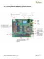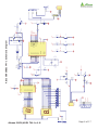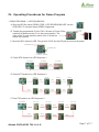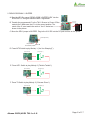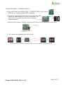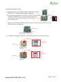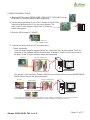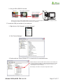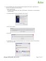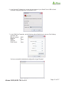
1
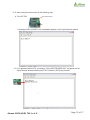
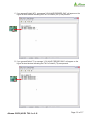
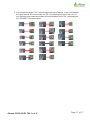
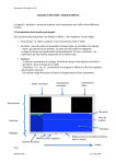
USER'S MANUAL
Getting started with
ALEXAN ATMEL
AT89C2051/AT89C4051
Training Module - 1
Version 1.0
Copyright © 2006
Ace Electronic Technology Inc.
All Rights Reserved
Alexan 2051/4051 TM-1 v.1.0
Page 1 of 17
About This Guide
In this User’s Manual, it is assumed that the user is familiar with microcontrollers
on the following aspects:
1. How to program using an MCU programmer
2. MCU pin-outs and I/O port functions
3. How to use, program and control LED, 7-segment display, buzzer, relay,
and serial port communication
4. How to read and interpret a schematic diagram
5. Knowledge on some electronic terms and devices
It is also assumed that the user is familiar in microcontroller programming either
in C or assembly language. The user must have knowledge on compiling/debugging
source codes. Moreover, it is also assumed that the user is knowledgeable on the
standards and safety precautions in operating electronics hardware and correct
handling of microcontrollers.
Alexan ATMEL AT89C2051/AT89C4051 Training Module – 1 and Alexan 89CX051
TM-1 refers to the same module and will be used alternately.
Alexan 2051/4051 TM-1 v.1.0
Page 2 of 17
I. Overview
This user’s manual will guide you on how to use the ALEXAN Training
Module 1 (TM-1).
The TM-1 is a helping tool in which you can explore the many features of a
microcontroller. This module uses ATMEL AT89C2051 and AT89C4051
microcontroller (MCU). This training module has the following applications:
1. 3-External Switches – INT0 (P3.2),INT1 (P3.3),T0 (P3.4)
2. 7-Segment Display
3. Buzzer
4. LEDs
5. Relay
6. RS232 Serial Communication
You must first be familiar with and understand the schematic diagram of the
training module to facilitate your programming.
Alexan 2051/4051 TM-1 v.1.0
Page 3 of 17
II. Getting Started
What you need to get started
1. 2051 Training Module-1
2. 6 to 9V DC Power Adaptor
3. ATMEL AT89C2051/AT89C4051 Microcontroller
4. 3-Pin Connector to Serial Connector for RS232
5. ATMEL Programmer
6. Debugger/Compiler for your source code
After writing your hex code into the microcontroller by means of an IC
programmer, insert your microcontroller into the 20-pin IC socket of your
training module.
Note: The notch of the IC socket must correspond to the notch of your MCU.
Incorrect placement may damage your MCU.
Move the jumper of SEL2 to select between LED display and 7-segment Display
(both are connected as Common Anode). Likewise, move the jumper of SEL1 to
select between Buzzer andRelay application (a 0 or LOW pulse is used to
activate buzzer and relay).
If you want to use the 2 digits of your 7-segment display, you can
enable/disable the transparent latch IC (74LS373).
Alexan 2051/4051 TM-1 v.1.0
Page 4 of 17
III. Training Module PCB and Schematic Diagram
Alexan 2051/4051 TM-1 v.1.0
Page 5 of 17
Alexan 2051/4051 TM-1 v.1.0
A
A
a
b
c
d
e
f
g
DP
7-SEGMENT1
A
A
a
b
c
d
e
f
g
DP
1
13
10
8
7
2
11
9
1
13
10
8
7
2
11
9
LED7
7-SEGMENT
LED
3-pin Con
LED6
5
9
4
8
3
7
2
6
1
TxD
RxD
DB 9 - Female Connector
LED8
1
2
3
R2
R3
R4
R5
R6
R7
R8
R9
LED5
RS232
470
470
470
470
470
470
470
470
LED4
VCC
3
14
3
14
7-SEGMENT2
2
5
6
9
12
15
16
19
Q1
Q2
Q3
Q4
Q5
Q6
Q7
Q8
Rx
Tx
470
470
470
470
470
470
470
470
GND
LE
D1
D2
D3
D4
D5
D6
D7
D8
R10
R11
R12
R13
R14
R15
R16
R17
IC1
VCC
OE
0.1uF
C9
4.7K
R21
4.7K
10K
R18
4.7K
R19
VCC
P1.0
P1.1
P1.2
P1.3
P1.4
P1.5
P1.6
P1.7
LE
P1.0
P1.1
P1.2
P1.3
P1.4
P1.5
P1.6
P1.7
R22
Q2
C8550
10
11
3
4
7
8
13
14
17
18
1
Q1
C9013
4.7K
R23
VCC
4.7K
R20
RESET
VCC
C3
10uF
Receive
Transmit
C2
30pF
R1
8.2K
VCC
VCC
Y1
2
0.1uF
C8
DC JACK
6V Input
1
P1.0
P1.1
P1.2
P1.3
P1.4
P1.5
P1.6
P1.7
1 2
3
2
C1
30pF
4
5
1
12
13
14
15
16
17
18
19
3
PWR SW 1
XTAL2
XTAL1
INT0
0.1uF
C6
10
20
INT1
T0
T0
R26
1K
VCC
0.1uF
C7
1K
Receive
Transmit
/INT0
/INT1
T0
LE
R28
100uF
C5
Q4
C9013
VCC
VCC
1N4733
ZD1
R29
2
3
6
7
8
9
11
/INT1
R25
1K
VCC
GND
VCC
P3.0 (RXD)
P3.1 (TXD)
P3.2 (INT 0)
P3.3 (INT1)
P3.4 (T0)
P3.5 (T1)
P3.7
/INT0
R24
1K
VCC
RST/VPP
P1.0
P1.1
P1.2
P1.3
P1.4
P1.5
P1.6
P1.7
MCU
1N4001
D2
1 K /0 .5 W
20
VCC
VCC
Alexan 89CX051 TM-1 Schematic Diagram
R27
1k
D1
Q3
VCC
LED9
4
5
RELAY
3
1
2
RELAY
BUZZER
LED1
LED2
LED3
Page 6 of 17
1
2
3
LOAD
BUZZER
IV. Operating Procedures for Demo Program
1. DEMO PROGRAM 1 - LED SEQUENCING
A. Burn the HEX file named “DEMO CODE - LED SEQUENCING.HEX” into the
AT89C2051 IC using the Alexan ATMEL Programmer.
B. Transfer the programmed IC to the TM-1. Be sure to Power Off the
module first. Make sure the IC is in the correct position. The
notch of the IC must match the notch of the IC socket as Notch on this side
shown in the picture.
89CX051
Power OFF
Power ON
Notch
IC Socket
IC
C. Move the SEL2 jumper to LED. Plug-in the 6-9V DC into the DC jack and turn on the power.
All LEDs will be ON
DC Jack(6-9V DC)
Jumper must be
on the LED position
Power ON
D. Press INT0 Switch to run LED Sequence 1.
[Scan Switches]
[ALL LEDs Off]
[ALL LEDs ON]
[Delay]
[Delay]
E. Press INT1 Switch to run LED Sequence 2.
[Scan Switches]
[LED8 ON]
[LED7 ON]
[Delay]
[LED6 ON]
[Delay]
[LED5 ON]
[Delay]
[Delay]
[Delay]
[Delay]
[LED1 ON]
[Delay]
[LED2 ON]
[Delay]
[LED3 ON]
[LED4 ON]
F. Press T0 Switch to run LED Sequence 3.
[Scan Switches]
[LED8+LED1 ON]
[Delay]
[LED7+LED2 ON]
[LED6+LED3 ON]
[LED5+LED4 ON]
[Delay]
[Delay]
[Delay]
[Delay]
[Delay]
[Delay]
[LED8+LED1 ON]
Alexan 2051/4051 TM-1 v.1.0
[LED7+LED2 ON]
[LED6+LED3 ON]
Page 7 of 17
2. DEMO PROGRAM 2 - BUZZER
A. Burn the HEX file named “DEMO CODE - BUZZER.HEX” into the
AT89C2051 IC using the Alexan ATMEL Programmer.
Power OFF
Power ON
89CX051
B. Transfer the programmed IC to the TM-1. Be sure to Power Off the
module first. Make sure the IC is in the correct position. The
notch of the IC must match the notch of the IC socket as Notch on this side
shown in the picture.
Notch
IC Socket
IC
C. Move the SEL1 jumper to BUZZER. Plug-in the 6-9V DC into the DC jack and turn on the power.
DC Jack(6-9V DC)
Jumper must be Power ON
on the Buzzer position
D. Press INT0 Switch to play Melody 1 (“Are You Sleeping?”).
[Scan Switches]
[Play Melody 1]
E. Press INT1 Switch to play Melody 2 (“Twinkle Twinkle”).
[Scan Switches]
[Play Melody 2]
F. Press T0 Switch to play Melody 3 (“Chinese Chime”).
[Scan Switches]
Alexan 2051/4051 TM-1 v.1.0
[Play Melody 3]
Page 8 of 17
3. DEMO PROGRAM 3 - 7-SEGMENT DISPLAY
A. Burn the HEX file named “DEMO CODE - 7-SEGMENT DISPLAY.HEX” into the
AT89C2051 IC using the Alexan ATMEL Programmer.
B. Transfer the programmed IC to the TM-1. Be sure to Power Off the
module first. Make sure the IC is in the correct position. The
notch of the IC must match the notch of the IC socket as
Notch on this side
shown in the picture.
89CX051
Power OFF
Power ON
Notch
IC Socket
IC
C. Move the SEL2 jumper to 7-SGMNT. Plug-in the 6-9V DC into the DC jack and turn on the power.
DC Jack(6-9V DC)
Jumper must be
on the 7-SGMNT position
Power ON
D. The 7-segment will repeatedly count up from 0-99.
[Counter=0]
[Counter+1]
[Counter+2]
[Counter+98]
[Counter+99]
[Count up(3 to 97)]
[Delay]
[Delay]
[Delay]
[Delay]
[Delay]
[Delay]
Alexan 2051/4051 TM-1 v.1.0
Page 9 of 17
4. DEMO PROGRAM 4 -RELAY
A. Burn the HEX file named “DEMO CODE - RELAY.HEX” into the
AT89C2051 IC using the Alexan ATMEL Programmer.
Power OFF
Power ON
89CX051
B. Transfer the programmed IC to the TM-1. Be sure to Power Off the
module first. Make sure the IC is in the correct position. The
notch of the IC must match the notch of the IC socket as Notch on this side
shown in the picture.
Notch
IC Socket
IC
C. Move the SEL1 jumber to RELAY and SEL2 jumper to LED. Plug-in the 6-9V DC into the
DC jack and turn on the power.
DC Jack(6-9V DC)
Power ON
Jumper must be
on the Relay position
Jumper must be
on the LED position
D. The RELAY will toggle ON and OFF if Switch INT0 and INT1 is pressed respectively.
RELAY STATUS
NC COM NO
NC = Normally Closed
COM = Common Connection
NO = Normally Open
LED 1 ON
Press and release
Switch INT0
RELAY STATUS
NC COM NO
NC = Normally Closed
COM = Common Connection
NO = Normally Open
LED1 OFF
Press and release
Switch INT1
Alexan 2051/4051 TM-1 v.1.0
Page 10 of 17
5. DEMO PROGRAM 5 -RS232
A. Burn the HEX file named “DEMO CODE - RS232 WITH 7-SEG.HEX” into the
AT89C2051 IC using the Alexan ATMEL Programmer.
Power OFF
Power ON
89CX051
B. Transfer the programmed IC to the TM-1. Be sure to Power Off the
module first. Make sure the IC is in the correct position. The
notch of the IC must match the notch of the IC socket as Notch on this side
shown in the picture.
Notch
IC Socket
IC
C. Move the SEL2 jumper to 7-SGMNT.
Jumper must be on
the 7-SGMNT position
D. Connect the serial port of your PC as shown below.
1. Direct Connection.
If your Personal Computer supports Serial Port, connect the TM-1 as shown below. The 3-pin
connector of TM-1(labeled RS232) where each pin is labeled 2, 3 and 5 must be connected to
the pins 2, 3 and 5 of your computer serial port respectively.
TM-1/TM-2
Back of PC: RS232 PORT
1
6
2
3
9
5
You can use a 3-pin connector (Female), RS232 9-pin connector (Female), and a MALE/FEMALE
RS232 Cable to simplify the above connection.
TM-1/TM-2
Back of PC: RS232 PORT
RS232 CABLE
532
2
3
5
Internal connection of Rs232 CABLE
1
2
3
4
5
9
6
9
6
1 2
3
4
5
Note: You can leave pins 1,4,6,7,8 and 9 unconnected, they are not useful in our application or you can also connect them,
as long as they are connected 1-to-1(Pin 1 Male to Pin 1 Female, Pin 4 Male to Pin 4 Female, and so on).
Alexan 2051/4051 TM-1 v.1.0
Page 11 of 17
2. Using a USB to RS232 Converter.
TM-1/TM-2
USB TO RS232 CONVERTER
5 3 2
Back of PC: USB PORT
Note: You can use any working USB to RS232 Converter, but first you must install the driver and locate its COM port number.
The COM port number of your serial port must be known for this application.
E. Locate the COM port number of your serial port.
1. Right-click on “My Computer” and click “Manage”.
2. Click “Device Manager”.
3. Double-click the “Ports (COM & LPT)” to view the list of connected devices.
Sample COM port number for USB to serial converter. In this example, the
converter is located on COM port 1. Take note that the driver of your USB
to serial converter automatically assigns the COM port number, so you
must identify the one you are using.
Note: Majority of the built-in serial port is designated as COM1.
Alexan 2051/4051 TM-1 v.1.0
Page 12 of 17
F. To run the RS232 demo code, the HyperTerminal program will be used. HyperTerminal is
included in the Windows Operating System.
1. Open HyperTerminal.
To open the HyperTerminal, click “Start > All Programs > Accessories > Communications
> HyperTerminal”
2. If prompted with the Location Information, click “Cancel”.
3. Click “Yes” to confirm.
4. Click “OK”.
5. In the Name box, type a name that describes your connection as shown in the example
below, then click “OK”.
.
Alexan 2051/4051 TM-1 v.1.0
Page 13 of 17
6. In the Connect To dialog box, choose the port number of your Serial Port or USB to Serial
converter using drop down box to connect to TM-1.
7. In the COM Port Properties, set the following values listed below to set your Port Settings
and click “OK”:
Bits per second:
9600
Data bits:
8
Parity:
None
Stop bits:
1
Flow Control:
None
You have successfully loaded and configured the HyperTerminal!
Alexan 2051/4051 TM-1 v.1.0
Page 14 of 17
8. To start running the demo code, do the following step:
DC Jack(6-9V DC)
A. Turn ON TM-1.
Power ON
A message “HELLO WORLD” will immediately appear on the HyperTerminal window.
B. If you pressed Switch INT0, a message “YOU HAVE PRESSED SW1” will appear on the
HyperTerminal window indicating that TM-1’s Switch1 (INT0) was pressed.
Alexan 2051/4051 TM-1 v.1.0
Page 15 of 17
C. If you pressed Switch INT1, a message “YOU HAVE PRESSED SW2” will appear on the
HyperTerminal window indicating that TM-1’s Switch2 (INT1) was pressed.
D. If you pressed Switch T0, a message “YOU HAVE PRESSED SW3” will appear on the
HyperTerminal window indicating that TM-1’s Switch3 (T0) was pressed.
Alexan 2051/4051 TM-1 v.1.0
Page 16 of 17
E. In the previous example, TM-1 communicated with HyperTerminal. In the next example,
the HyperTerminal will communicate with TM-1. By pressing keys 0 to 9 and A to F of
your keyboard, each character pressed will be immediately sent to TM-1 and displayed
on 7-SEGMENT1 as shown below.
Alexan 2051/4051 TM-1 v.1.0
Page 17 of 17