1
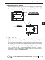
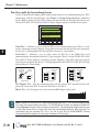
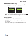
MAINTENANCE
CHAPTER
7
In This Chapter...
Project Backup . . . . . . . . . . . . . . . . . . . . . . . . . . . . . . . . . . . . . . . . . . . . . . . . . . . . . .7–2
Check Operating Environment . . . . . . . . . . . . . . . . . . . . . . . . . . . . . . . . . . . . . . . . .7–2
Check Operating Voltage . . . . . . . . . . . . . . . . . . . . . . . . . . . . . . . . . . . . . . . . . . . . .7–2
Check Transmit and Receive Indicators . . . . . . . . . . . . . . . . . . . . . . . . . . . . . . . . . .7–3
Check Physical Conditions . . . . . . . . . . . . . . . . . . . . . . . . . . . . . . . . . . . . . . . . . . . .7–3
Run Tests under the System Setup Screens . . . . . . . . . . . . . . . . . . . . . . . . . . . . . . .7–4
Check Settings under the System Setup Screens . . . . . . . . . . . . . . . . . . . . . . . . . .7–5
Cleaning the Display Screen . . . . . . . . . . . . . . . . . . . . . . . . . . . . . . . . . . . . . . . . . . .7–5
Check Project Functionality . . . . . . . . . . . . . . . . . . . . . . . . . . . . . . . . . . . . . . . . . . .7–6
Checks from the C-more Micro-Graphic Programming Software . . . . . . . . . . . . . .7–6
Chapter 7: Maintenance
1
2
3
4
5
6
7
8
9
10
11
12
13
14
A
B
C
D
Maintenance
7–2
Although the C-more® Micro-Graphic panels require very little maintenance, setting up a
routine maintenance schedule will insure the longevity of the product in your application.
The following are some suggestions of items to include in a preventive maintenance list or
schedule. Most of these items should be scheduled quarterly or bi-annually.
Project Backup
During a routine preventive maintenance check is a good time to make sure that there is an upto-date backup of the application project. Although the C-more Micro-Graphic panel with its
programming software has the ability to upload the complete project from a panel, insurance is
warranted just in case the worse case scenario happens and the entire panel is destroyed.
Check Operating Environment
Make sure the Micro-Graphic panel is
operating in the proper temperature
range: (0 to 50 °C (32 to 122 °F)).
Make sure the Micro-Graphic panel is
operating within the specified humidity range:
(5–95% RH, non-condensing).
Make sure the operating environment is free of corrosive gasses.
CORROSIVE
8
Check Operating Voltage
Check the input voltage that is powering the Micro-Graphic panel to make sure it is within the
appropriate range.
5 VDC: If the panel is being powered with 5 VDC from an AutomationDirect PLC’s
RJ12 serial communications port to Port 1 on the panel, the acceptable voltage
range to the panel is 4.75-5.25 VDC (1.05 W @ 5 VDC (210 mA)).
24 VDC: If the panel is being powered from the optional EA-MG-P1 DC Power
Adapter, or the EA-MG-SP1 Serial Port with DC Power Adapter, the
acceptable voltage range to the adapter is 10.8-26.4 VDC (100 mA @ 24
VDC).
®
EA1-MG-USER-M Hardware User Manual, 2nd Ed. Rev. C, 06/13
Chapter 7: Maintenance
Check Transmit and Receive Indicators
During a routine maintenance check is a good time to take a quick look at the status indicators
on the back of the C-more Micro-Graphic panel, and the EA-MG-SP1 Serial Port w/ DC
Power Adapter, if being used. There should be activity on both the TxD and RxD LED
indicators when connected serially to a PLC or control device from either port.
TxD
Indicator
Micro-Graphic Panel
Port 1 Status Indicators
RxD
Indicator
TxD
Indicator
RxD
Indicator
EA-MG-SP1
Port 2 Status Indicators
Port 2
Check Physical Conditions
Make sure that harmful chemicals are not being used around the C-more Micro-Graphic panel.
Look for any deterioration of the panel’s bezel and front display area. See Chapter 2:
Specifications for identification of the materials on the face of the panels and accessory bezels.
Check the mounting gasket to make sure it is sealing properly and has not deteriorated. Replace
the mounting gasket if there are any signs of deterioration, or if there is any evidence that
moisture/liquids have penetrated to the inside of the enclosure where the panel is mounted.
Information on replacement gaskets can be found in Chapter 9: Replacement Parts.
Check to make sure that none of the cooling vents around the inside section of the MicroGraphic panel are clogged with dust or debris. Also make sure that there is clearance around the
panel as shown in Chapter 4: Installation and Wiring.
®
EA1-MG-USER-M Hardware User Manual, 2nd Ed. Rev. C, 06/13
1
2
3
4
5
6
7
8
9
10
11
12
13
14
A
B
C
D
7–3
Chapter 7: Maintenance
Run Tests under the System Setup Screens
1
2
3
4
5
6
7
8
9
10
11
12
13
14
A
B
C
D
7–4
Use the C-more Micro-Graphic panel’s System Setup Screens to test communication ports, PLC
connectivity, and the internal beeper. See Chapter 5: System Setup Screens for additional
details. Below is shown the Test Menu. Please note the Serial Port2 selection will only be seen
when the EA-MG-SP1 Serial Port with DC Power Adapter option is installed on the panel.
TEST MENU
1.Serial Port1 - Loop Back Test
2.Serial Port2 - Loop Back Test
3.PLC Enquiry Test
4.Buzzer Test
BAK
--
UP
DWN
ENT
F1
F2
F3
F4
F5
Serial Port 1 - Performs a test to verify the RJ12 serial communications port (Port 1) on the
panel is operating correctly. Requires a loop back connector inserted into the port to properly
run the test. A wiring diagram for the loop back connector is shown below.
Serial Port 2 - Performs a test to verify either the RS-232 or the RS485/422 serial
communications functionality from the 15-pin connector (Port 2) on the EA-MG-SP1 Serial
Port with DC Power Adapter is operating correctly. Requires a loop back connector inserted
into the port to properly run the test. A wiring diagram for either a RS-232 or RS-485/422 loop
back connector is shown below.
RJ12 Loop-back Connector
RJ12 6-pin
Phone Plug
(6P6C)
Jumper
Pin 3 to 4
RS-232 Loop-back Connector
15-pin D-sub
(male)
2
TXD
3
RXD
3
RXD
7
4
CTS
TXD
8
RTS
123456
Wiring Diagram
15
1
Wiring Diagram
RS-422/485 Loop-back Connector
7 CTS 15-pin D-sub
(male)
8
RTS
9
RXD+
11
TXD+
10
RXD–
12
TXD–
15
1
Wiring Diagram
PLC Enquiry Test - Tests the communications with the selected PLC protocol between the
panel and a connected PLC. Is used with both Port 1 and Port 2.
Buzzer Test - Use this option to test the internal audible beeper of the panel.
NOTE: The panel has one built-in RJ12 serial communications port (Port 1 - RS-232) and the option to add
one 15-pin serial communications port (Port 2 - RS-232/422/485) to the panel by installing the EA-MG-SP1
module. Only one of the ports can be used with a connected PLC. The programming software allows the user
to select either Comm. Port1 or Comm. Port2 under the Panel Manager dialog box. When using Port 2 to
communicate with the connected PLC, Port 1 can still be used with the EA-MG-PGM-CBL Software
Programming Cable Assembly to transfer projects between the PC and panel.
®
EA1-MG-USER-M Hardware User Manual, 2nd Ed. Rev. C, 06/13
Chapter 7: Maintenance
Check Settings under the System Setup Screens
Use the C-more Micro-Graphic panel’s System Setup Screens to check the various settings such
as the LCD contrast, background color, beep, etc. See Chapter 5: System Setup Screens for
additional details. Below is shown the Setting Menu. Note the use of the up/down keys to access
the last item.
SETTING
SETTING
1.LCD Contrast
2.Backlight
3.Beep
4.Calibration
5.Clear User Memory
>
>
>
6.Reset Factory Default
BAK
NXT
UP
DWN
ENT
BAK
NXT
UP
DWN
ENT
F1
F2
F3
F4
F5
F1
F2
F3
F4
F5
LCD Contrast - Used to adjust the LCD display’s contrast. The default is a value of 3, and the
range is 1 to 5, with 5 being the highest contrast.
Backlight - There are five different available backlight colors. Use this option to select the
default screen color and also cycle through the colors for checking.
Cleaning the Display Screen
The display screen should be cleaned periodically by wiping it with a lint free damp cloth using
a mild soap solution. Dry the surface when finished with a lint free cloth. Do not clean with
ammonia based products. The ABS material the bezel is made from is reactive with ammonia.
The longevity of the display screen on the touch screen models can be increased by the use of a
EA-MG-COV-CL clear screen overlay. See Chapter 3: Accessories for additional information
on the screen overlay.
To prevent damage to the display screen on the touch screen models, avoid touching the screen
with sharp objects, striking the screen with a hard object, using abrasives near the screen, or
using excessive force when pressing the touch screen.
®
EA1-MG-USER-M Hardware User Manual, 2nd Ed. Rev. C, 06/13
1
2
3
4
5
6
7
8
9
10
11
12
13
14
A
B
C
D
7–5
Chapter 7: Maintenance
Check Project Functionality
1
2
3
4
5
6
7
8
9
10
11
12
13
14
A
B
C
D
7–6
During a routine maintenance check is a good time to verify the functionality of your
application, making sure that various areas on different screens do what they were designed to
do. An outline or specification for the application is a useful tool for testing the various aspects
of your application. As a starting point, you may want to run through all the screens to make
sure they are accessible.
If there are any trouble-shooting procedures built into the Micro-Graphic panel application,
now is a good time to also check these aids.
Checks from the C-more Micro-Graphic Programming Software
If you have a PC available with the C-more Micro-Graphic Programming Software,
EA-MG-PGMSW, installed, and the PC is connected to the panel, you can check the status of
the panel by using the Panel Information window.
The Panel Information window shown below will indicate the panel type, any options such as
a keypad bezel or DC power adapter that have been installed, the total memory, memory used,
free memory, firmware version, mask ROM version, and the PLC protocol the panel has been
setup for using on its serial communication port. The programming software can also be used
to update the panel’s firmware to the latest version.
®
EA1-MG-USER-M Hardware User Manual, 2nd Ed. Rev. C, 06/13
Chapter 7: Maintenance
Notes:
_____________________________________________________________
_____________________________________________________________
_____________________________________________________________
_____________________________________________________________
_____________________________________________________________
_____________________________________________________________
_____________________________________________________________
_____________________________________________________________
_____________________________________________________________
_____________________________________________________________
_____________________________________________________________
_____________________________________________________________
_____________________________________________________________
_____________________________________________________________
_____________________________________________________________
_____________________________________________________________
_____________________________________________________________
_____________________________________________________________
_____________________________________________________________
_____________________________________________________________
_____________________________________________________________
_____________________________________________________________
_____________________________________________________________
_____________________________________________________________
_____________________________________________________________
_____________________________________________________________
_____________________________________________________________
_____________________________________________________________
_____________________________________________________________
_____________________________________________________________
_____________________________________________________________
_____________________________________________________________
_____________________________________________________________
®
EA1-MG-USER-M Hardware User Manual, 2nd Ed. Rev. C, 06/13
1
2
3
4
5
6
7
8
9
10
11
12
13
14
A
B
C
D
7–7