1
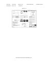
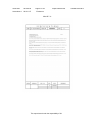
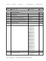
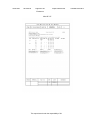
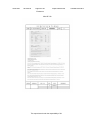
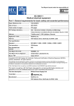
Ref. Certif. No.
DK-28210-M2-UL
IEC SYSTEM FOR MUTUAL RECOGNITION OF TEST
CERTIFICATES FOR ELECTRICAL EQUIPMENT
(IECEE) CB SCHEME
SYSTEME CEI D’ACCEPTATION MUTUELLE DE
CERTIFICATS D’ESSAIS DES EQUIPEMENTS
ELECTRIQUES (IECEE) METHODE OC
CB TEST CERTIFICATE CERTIFICAT D’ESSAI OC
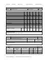
Product
Produit
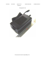
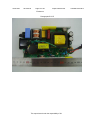
Switching Power Supply
Name and address of the applicant
Nom et adresse du demandeur
BRIDGEPOWER CORP
964 GOSAEK-DONG GWONSEON-GU SUWON-SI
GYEONGGI-DO 441-813 KOREA
Name and address of the manufacturer
Nom et adresse du fabricant
BRIDGEPOWER CORP
964 GOSAEK-DONG GWONSEON-GU SUWON-SI
GYEONGGI-DO 441-813 KOREA
Name and address of the factory
Nom et adresse de l’usine
BRIDGEPOWER CORP
964 GOSAEK-DONG GWONSEON-GU SUWON-SI
GYEONGGI-DO 441-813
KOREA
Note: When more than one factory, please report on page 2
Note: Lorsque il y plus d'une usine, veuillez utiliser la 2ème page
Additional Information on page 2
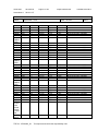
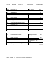
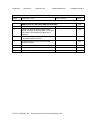
Ratings and principal characteristics
Valeurs nominales et caractéristiques principales
See Page 3
Trademark (if any)
Marque de fabrique (si elle existe)
None
Type of Manufacturer's Testing Laboratories used
Type de programme du laboratoire d'essais
constructeur
Model / Type Ref.
Ref. De type
Models CENB1100********, MENB1100********,
JMW1100*********, JPW1100*********,
See Page 2
Additional information (if necessary may also be
reported on page 2)
Les informations complémentaires (si nécessaire,,
peuvent être indiqués sur la 2ème page
Additional Information on page 3
A sample of the product was tested and found
to be in conformity with
Un échantillon de ce produit a été essayé et a été
considéré conforme à la
IEC 60950-1(ed.2), IEC 60950-1(ed.2);am1
As shown in the Test Report Ref. No. which forms part
of this Certificate
Comme indiqué dans le Rapport d’essais numéro de
référence qui constitue partie de ce Certificat
E300305-A33-CB-4 issued on 2013-01-16
This CB Test Certificate is issued by the National Certification Body
Ce Certificat d’essai OC est établi par l’Organisme National de Certification
UL (US), 333 Pfingsten Rd IL 60062, Northbrook, USA
UL (Demko), Borupvang 5A DK-2750 Ballerup, DENMARK
UL (JP), Marunouchi Trust Tower Main Building 6F, 1-8-3 Marunouchi, Chiyoda-ku, Tokyo 100-0005, JAPAN
UL (CA), 7 Underwriters Road, Toronto, M1R 3B4 Onta
Ontario, CANADA
For
F
Fo
o full legal entity names see www.ul.com/ncbnames
Date: 2013-01-16
Signature:
Original Issue Date: 2012-09-24
Jan-Erik Storgaa
Storgaard
aard
aa
1/3
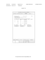
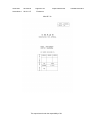
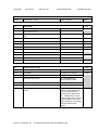
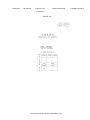
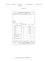
Ref. Certif. No.
DK-28210-M2-UL
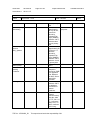
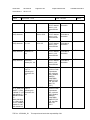
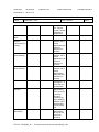
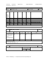
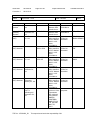
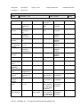
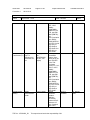
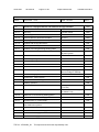
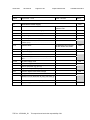
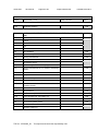
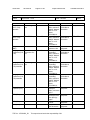
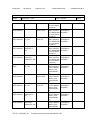
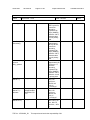
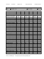
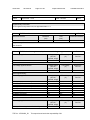
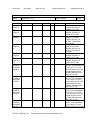
Model Details:
CENB1100 * ** ** * **
(b) (c) (d) (f) (e)
(b) means design revision changes, may be A to Z;
(c) means output voltages, may be 12, 13, 15, 16, 18,19, 24 or 48;
(d) means standards output cord options, may be 00 to 99;
(e) means custom options, may be 00 to 99 or AA to ZZ.
(f) means class type, maybe F(ClassI) or Q (ClassII) or N(ClassII)
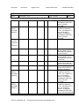
JMW1100 * * ** ** *
(a) (b) (c) (d) (f)
**
(e)
(a) means custom options, may be A to Z;
(b) means design revision changes, may be A to Z;
(c) means output voltages, may be 12, 13, 15, 16, 18,19, 24 or 48;
(d) means standards output cord options, may be 00 to 99;
(e) means custom options, may be 00 to 99 or AA to ZZ.
(f) means class type, maybe F(ClassI) or Q (ClassII) or N(ClassII)
JPW1100 * * ** ** * **
(a) (b) (c) (d) (f) (e)
(a) means custom options, may be A to Z;
(b) means design revision changes, may be A to Z;
(c) means output voltages, may be 12, 13, 15, 16, 18,19, 24 or 48;
(d) means standards output cord options, may be 00 to 99;
(e) means custom options, may be 00 to 99 or AA to ZZ.
(f) means class type, maybe F(ClassI) or Q (ClassII) or N(ClassII)
MENB1100 * ** ** * **
(b) (c) (d) (f) (e)
(b) means design revision changes, may be A to Z;
(c) means output voltages, may be 12, 13, 15, 16, 18,19, 24 or 48;
(d) means standards output cord options, may be 00 to 99;
(e) means custom options, may be 00 to 99 or AA to ZZ.
(f) means class type, maybe F(ClassI) or Q (ClassII) or N(ClassII)
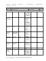
Factories:
WENDENG JEIL ELECTRONICS CO LTD
DONG SHOU GUANGZHOU LU KAIFA-QU WENDENG-SHI SHANDONG
CHINA
Additional information (if necessary)
Information complémentaire (si nécessaire)
UL (US), 333 Pfingsten Rd IL 60062, Northbrook, USA
UL (Demko), Borupvang 5A DK-2750 Ballerup, DENMARK
UL (JP), Marunouchi Trust Tower Main Building 6F, 1-8-3 Marunouchi, Chiyoda-ku, Tokyo 100-0005, JAPAN
UL (CA), 7 Underwriters Road, Toronto, M1R 3B4 Ontario, CANADA
For full legal entity names see www.ul.com/ncbnames
Date: 2013-01-16
Original Issue Date: 2012-09-24
Signature:
Jan-Erik Storgaard
2/3
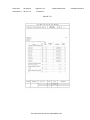
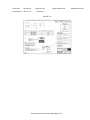
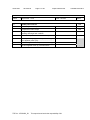
Ref. Certif. No.
DK-28210-M2-UL
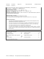
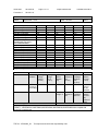
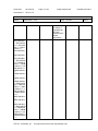
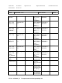
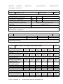
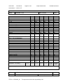
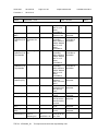
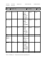
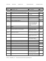
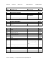
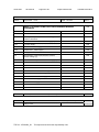
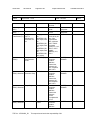
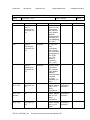
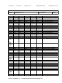
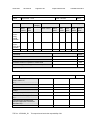
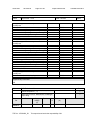
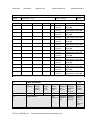
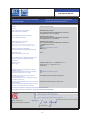
Ratings:
Input Rating: 100-240 Vac, 50-60 Hz, 2.0 A
Output Rating: 12.0 Vdc, 7.5 A or
13.0 Vdc, 6.92A or
15.0 Vdc, 6.4 A or
16.0Vdc, 6.0 A or
18.0 Vdc, 5.6 A or
19.0 Vdc, 5.2A or
24.0 Vdc, 4.2 A or
48.0 Vdc, 2.1A
Additional Information:
The original report was modified to include the following changes/additions:
Add class of category.
Correct required clearance and creepage in Table.
Additionally evaluated to EN60950-1:2006/A11:2009/A1:2010/A12:2011;
National Differences specified in the CB Test Report.
Additional information (if necessary)
Information complémentaire (si nécessaire)
UL (US), 333 Pfingsten Rd IL 60062, Northbrook, USA
UL (Demko), Borupvang 5A DK-2750 Ballerup, DENMARK
UL (JP), Marunouchi Trust Tower Main Building 6F, 1-8-3 Marunouchi, Chiyoda-ku, Tokyo 100-0005, JAPAN
UL (CA), 7 Underwriters Road, Toronto, M1R 3B4 Ontario, CANADA
For full legal entity names see www.ul.com/ncbnames
Date: 2013-01-16
Original Issue Date: 2012-09-24
Signature:
Jan-Erik Storgaard
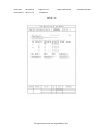
3/3
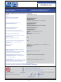
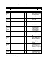
Issue Date:
2012-09-24
Correction 2
2013-01-16
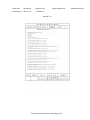
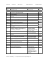
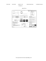
Page 1 of 11
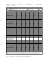
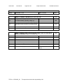
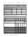
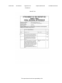
Report Reference #
E300305-A33-CB-4
Test Report issued under
the responsibility of:
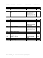
TEST REPORT
IEC 60950-1
Information technology equipment - Safety Part 1: General requirements
Report Reference No .................. :
E300305-A33-CB-4
Date of issue ................................. :
2012-09-24
Total number of pages .................. :
11
CB Testing Laboratory ............... :
UL Korea, Ltd.
Address ......................................... :
#808, Manhatan Building, 36-2 Yeouido-Dong, Yeongdeungpo-Gu,
Seoul 150-749, Korea
Applicant's name ........................ :
BRIDGEPOWER CORP
964 GOSAEK-DONG
GWONSEON-GU
SUWON-SI GYEONGGI-DO 441-813 KOREA
Address ......................................... :
Test specification:
Standard ........................................ :
IEC 60950-1:2005 (2nd Edition); Am 1:2009
Test procedure .............................. :
CB Scheme
Non-standard test method ............ :
N/A
Test Report Form No. ................. :
IEC60950_1B
Test Report Form originator .......... :
SGS Fimko Ltd
Master TRF ................................... :
2010-04
Copyright © 2010 IEC System for Conformity Testing and Certification of Electrical Equipment
(IECEE), Geneva, Switzerland. All rights reserved.
This publication may be reproduced in whole or in part for non-commercial purposes as long as the IECEE is
acknowledged as copyright owner and source of the material. IECEE takes no responsibility for and will not
assume liability for damages resulting from the reader's interpretation of the reproduced material due to its
placement and context.
If this test Report is used by non-IECEE members, the IECEE/IEC logo and the reference to the CB Scheme
procedure shall be removed.
This report is not valid as a CB Test Report unless signed by an approved CB Testing Laboratory and
appended to a CB Test Certificate issued by an NCB in accordance with IECEE 02.
TRF No. : IEC60950_1B
This report issued under the responsibility of UL
Issue Date:
2012-09-24
Correction 2
2013-01-16
Page 2 of 11
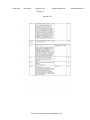
Report Reference #
E300305-A33-CB-4
Test item description .................. :
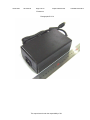
Switching Power Supply
Trade Mark .................................... :
None
Manufacturer ................................. :
BRIDGEPOWER CORP
964 GOSAEK-DONG
GWONSEON-GU
SUWON-SI GYEONGGI-DO 441-813 KOREA
Model/Type reference ................... :
Models CENB1100********, MENB1100********, and
JMW1100********* and JPW1100*********
Ratings .......................................... :
Input Rating: 100-240 Vac, 50-60 Hz, 2.0 A
Output Rating: 12.0 Vdc, 7.5 A or
13.0 Vdc, 6.92A or
15.0 Vdc, 6.4 A or
16.0Vdc, 6.0 A or
18.0 Vdc, 5.6 A or
19.0 Vdc, 5.2A or
24.0 Vdc, 4.2 A or
48.0 Vdc, 2.1A
TRF No. : IEC60950_1B
This report issued under the responsibility of UL
Issue Date:
2012-09-24
Correction 2
2013-01-16
Page 3 of 11
Report Reference #
E300305-A33-CB-4
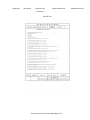
Testing procedure and testing location:
[x]
CB Testing Laboratory
Testing location / address .............. :
[ ]
UL Korea, Ltd. #808, Manhatan Building, 36-2 Yeouido-Dong,
Yeongdeungpo-Gu, Seoul 150-749, Korea
Associated CB Test Laboratory
Testing location / address .............. :
[ ]
Tested by (name + signature) ....... :
InYoung Hwang
Approved by (name + signature) ... :
ByeongUk Lee
Testing Procedure: TMP
Tested by (name + signature) ....... :
Approved by (+ signature) ............. :
Testing location / address .............. :
[ ]
Testing Procedure: WMT
Tested by (name + signature) ....... :
Witnessed by (+ signature) ............ :
Approved by (+ signature) ............. :
Testing location / address .............. :
[ ]
Testing Procedure: SMT
Tested by (name + signature) ....... :
Approved by (+ signature) ............. :
Supervised by (+ signature) .......... :
Testing location / address .............. :
[ ]
Testing Procedure: RMT
Tested by (name + signature) ....... :
Approved by (+ signature) ............. :
Supervised by (+ signature) .......... :
Testing location / address .............. :
List of Attachments
National Differences (0 pages)
Enclosures (0 pages)
Summary of Testing:
No tests were conducted
Summary of Compliance with National Differences:
Countries outside the CB Scheme membership may also accept this report.
List of countries addressed: AT, BE, CA, CH, CN, CZ, DE, DK, ES, EU, FI, FR, GB, GR, HU, IE, IL, IT, JP,
KR, NL, NO, PL, PT, SE, SG, SI, SK, US
TRF No. : IEC60950_1B
This report issued under the responsibility of UL
Issue Date:
2012-09-24
Correction 2
2013-01-16
Page 4 of 11
Report Reference #
The product fulfills the requirements of: N/A
Copy of Marking Plate - Refer to Enclosure titled Marking Plate for copy.
TRF No. : IEC60950_1B
This report issued under the responsibility of UL
E300305-A33-CB-4
Issue Date:
2012-09-24
Correction 2
2013-01-16
Page 5 of 11
Report Reference #
E300305-A33-CB-4
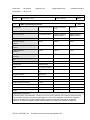
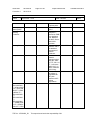
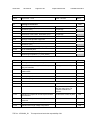
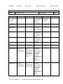
Test item particulars :
Equipment mobility ...............................................:
movable
Connection to the mains ......................................:
pluggable A
Operating condition ..............................................:
continuous
Access location ....................................................:
N/A
Over voltage category (OVC) ..............................:
OVC II
Mains supply tolerance (%) or absolute mains supply
values ...................................................................:
+10%, -10%
Tested for IT power systems ...............................:
Yes(for Norway only)
IT testing, phase-phase voltage (V) .....................:
230 Vac
Class of equipment ..............................................:
Class I (earthed) or ClassII(double insulated)
Considered current rating of protective device as part
of the building installation (A) ...............................:
2.0
Pollution degree (PD) ...........................................:
PD 2
IP protection class ................................................:
IP X0
Altitude of operation (m) .......................................:
up to 5000m
Altitude of test laboratory (m) ...............................:
N/A
Mass of equipment (kg) .......................................:
0.7
Possible test case verdicts:
- test case does not apply to the test object ........... :
N/A
- test object does meet the requirement ................. :
P(Pass)
- test object does not meet the requirement ........... :
F(Fail)
Testing:
Date(s) of receipt of test item ...............................:
N/A
Date(s) of Performance of tests ...........................:
N/A
General remarks:
The test results presented in this report relate only to the object tested.
This report shall not be reproduced, except in full, without the written approval of the testing laboratory.
"(see Enclosure #)" refers to additional information appended to the report.
"(see appended table)" refers to a table appended to the report.
Throughout this report a point is used as the decimal separator.
Manufacturer's Declaration per Sub Clause 6.25 of IECEE 02:
Yes
The application for obtaining a CB Test Certificate includes more than one factory and a
declaration form the Manufacturer stating that the sample(s) submitted for evaluation is (are)
representative of the products from each factory has been provided ......
When differences exist, they shall be identified in the General Product Information section.
Name and address of Factory(ies):
TRF No. : IEC60950_1B
BRIDGEPOWER CORP
964 GOSAEK-DONG
GWONSEON-GU
This report issued under the responsibility of UL
Issue Date:
2012-09-24
Correction 2
2013-01-16
Page 6 of 11
Report Reference #
E300305-A33-CB-4
SUWON-SI GYEONGGI-DO 441-813 KOREA
WENDENG JEIL ELECTRONICS CO LTD
DONG SHOU GUANGZHOU LU
KAIFA-QU
WENDENG-SHI SHANDONG CHINA
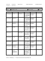
GENERAL PRODUCT INFORMATION:
Report Summary
The original report was modified on 2013-01-16 to include the following changes/additions:
E300305-A33-CB-4, Correction2
- Add class of category ; ClassII(double insulated) due to missing.
- Correct required clearance and creepage in table 2.10.2 and 2.10.3 from 7.7 to 7.1 due to error.
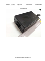
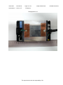
Product Description
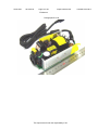
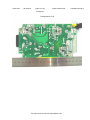
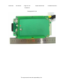
Switching Power Supply (AC/DC adapter), consists of electronic components mounted on PWB, a switching
transformer and electronic components mounted on PWB, housed with a plastic enclosure.
Model Differences
Models CENB1100********, MENB1100********, and JMW1100********* and JPW1100********* (Where * may
be alphanumeric, "for marketing purpose and no impact safety related critical components and
constructions")
Models CENB1100********, MENB1100********, and JMW1100********* are identical to JPW1100*********,
except model designations as follows;
Nomenclature
JPW1100 * * ** ** * **
(a) (b) (c) (d) (f) (e)
or JMW1100 * * ** ** *
**
(a) (b) (c) (d) (f) (e)
or CENB1100 * ** **
* **
(b) (c) (d) (f) (e)
or MENB1100 * ** ** * **
(b) (c) (d) (f) (e)
(a) means custom options, may be A to Z;
(b) means design revision changes, may be A to Z;
(c) means output voltages, may be 12, 13, 15, 16, 18,19, 24 or 48;
(d) means standards output cord options, may be 00 to 99;
(e) means custom options, may be 00 to 99 or AA to ZZ.
(f) means class type, maybe F(ClassI) or Q (ClassII) or N(ClassII)
The marked models as 12, 13, 15, 16, 18, 19 , 24 and 48 on (c) nomenclature are identical individually,
except model designations, output ratings, transformers and secondary circuits.
TRF No. : IEC60950_1B
This report issued under the responsibility of UL
Issue Date:
2012-09-24
Correction 2
2013-01-16
Page 7 of 11
Report Reference #
E300305-A33-CB-4
The Models JPW1100**13*****, JPW1100**16*****, CENB1100*13*****,CENB1100*16*****,
JMW1100**13*****, JMW1100**16*****, MENB1100*13*****, and MENB1100*16***** are identical to Model
JPW1100**12***** except for model designation, output ratings, transformers and secondary circuits.
The model JPW1100**19*****, CENB1100*19*****, JMW1100**19*****, MENB1100*19***** are identical to
JPW1100**12***** except for model designation, output ratings, transformers and secondary circuits.
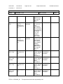
Additional Information
Maximum Normal Load Condition: Rated Output Currents
JPW1100KA1200F01: 12.0 Vdc, 7.5 A;
JPW1100KA1500F01: 15.0 Vdc, 6.4 A;
JPW1100KA1800F01: 18.0 Vdc, 5.6 A;
JPW1100KA2400F01: 24.0 Vdc, 4.2 A.
This equipment is not provided with user's manual.
Procedure Deviation:
Argentina*, Australia / New Zealand, Austria**, Belgium**, China, Czech Republic**, Denmark, Finland,
France**, Germany, Greece**, Group, Hungary*, India*, Ireland*, Israel*, Italy*, Japan*, Kenya*, Korea,
Malaysia*, Netherlands**, Norway, Poland*, Portugal*, Singapore*, Slovakia**, Slovenia*, Spain*, Sweden,
Switzerland**, and United Kingdom.
* - No National Differences Declared, ** - Only Group Differences.
Before placing the products in the different countries, the manufacturer has to guarantee that:
1. Operating instructions and warnings are written in an accepted language of the certain country.
2. The equipment is in compliance with the national standards of the certain country.
E300305-A33-CB-3, Reissue
- Added Thermal Fuse (Seki Controls Co., Ltd., Type ST-22) in critical component list.
E300305-A33-CB-4, Reissue
- Upgrade report from IEC 60950-1 2nd edition to IEC 60950-1 2nd edition, Amendment1
- Altitude of operation is up to 2000m to up to 5000m refer to IEC 60664-1 table A.2
- Humidity test was conducted at 40 degreeC, 95% , 120hours for China Deviation.
- National Difference for China is revised.
- Tma is changed from 30 degreeC to 35 degreeC
E300305-A33-CB-4, Correction1
- Add optical isolator certification information under mark of conformity section due to missing
- Add bobbin's manufacturer name due to missing
- Correct optical isolator CR,CL from "thermal cycling conducted " to measured CR, CP in table 2.10.2 ,
2.10.3 and 2.10.4 due to typo error
- Delete Enclosure type HN-1064W(+) in critical component list due to typo error
- Correct electric strength table due to typo error
E300305-A33-CB-4, Amendment 1(12CA56785)
- Alternate appliance inlet type SS-120A,RF-180 by Rong Feng Industrial Co., Ltd
- Alternate linefilter 3025671B
- Alternate Y-Capacitor(CY1,CY2) type SE or SB , 250V, maximum 1500pF by Success Electronics Co., Ltd
- Alternate Y-Capacitor(CY1,CY2) type KX or KY , 250V, maximum 1500pF by Murata Mfg.Co., Ltd
- Alternate Y-Capacitor(CY3,CY4) type SE or SB , 250V, maximum 1000pF by Success Electronics Co., Ltd
- Alternate Y-Capacitor(CY3,CY4) type KX or KY , 250V, maximum 1000pF by Murata Mfg.Co., Ltd
TRF No. : IEC60950_1B
This report issued under the responsibility of UL
Issue Date:
2012-09-24
Correction 2
2013-01-16
Page 8 of 11
Report Reference #
E300305-A33-CB-4
- Add electrical output rating ; 48Vdc/2.1A (transformer type 3025579005A ) ; JPW1100**48*****,
JMW1100**48*****, CENB1100*48*****,MENB1100*48*****
- Add insulator sheet and shield.
- Alternate ClassII type ; JPW1100******Q***, JMW1100******Q**,
CENB1100*****Q**,MENB1100*****Q**,JPW1100******N***, JMW1100******N**,
CENB1100*****N**,MENB1100*****N**
- Add supplementary information in table 5.2, table 2.10.3 and 2.10.4 , optical isolator table(1,5,1),table C.2
- Revise manufacturer declaration letter
E300305-A33-CB-4, Correction2
- Add class of category ; ClassII(double insulated) due to missing.
- Correct required clearance and creepage in table 2.10.2 and 2.10.3 from 7.7 to 7.1 due to error.
Technical Considerations
The product was submitted and evaluated for use at the maximum ambient temperature (Tma)
permitted by the manufacturer’s specification of: 35
The means of connection to the mains supply is: Pluggable A, Detachable Power Supply Cord,
The product is intended for use on the following power systems: TN and IT (for Norway only),
The equipment disconnect device is considered to be: Appliance Inlet
The product was investigated to the following additional standards: EN 60950-1:2006 + A11:2009 +
A1:2010 + A12:2011 (which includes all European national differences, including those specified in
this test report).
Abbreviations used in the report:
- normal condition ............................................N.C.
:
- single fault condition ....................................... S.F.C
:
- operational insulation .....................................OP
:
- basic insulation .............................................. BI
:
- basic insulation between parts of opposite
polarity:
- supplementary insulation ............................... SI
:
BOP
- double insulation ............................................DI
:
- reinforced insulation ...................................... RI
:
Indicate used abbreviations (if any)
TRF No. : IEC60950_1B
This report issued under the responsibility of UL
Issue Date:
2012-09-24
Correction 2
2013-01-16
Page 9 of 11
Report Reference #
E300305-A33-CB-4
IEC 60950-1
Clause
Requirement + Test
Result - Remark
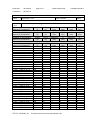
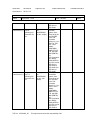
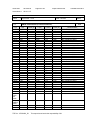
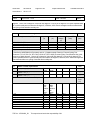
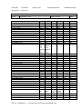
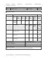
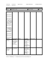
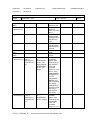
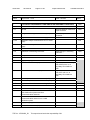
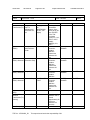
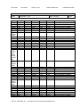
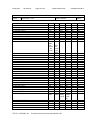
2.10.3 and TABLE: clearance and creepage distance measurements
2.10.4
Clearance (cl) and creepage
U peak
U r.m.s.
Required cl
cl
distance (cr) at/of/between:
(V)
(V)
(mm)
(mm)
Functional:
Clearance (cl) and creepage
U peak
U r.m.s.
Required cl
cl
distance (cr) at/of/between:
(V)
(V)
(mm)
(mm)
Basic/supplementary:
Clearance (cl) and creepage
U peak
U r.m.s.
Required cl
cl
distance (cr) at/of/between:
(V)
(V)
(mm)
(mm)
Reinforced:
Clearance (cl) and creepage
U peak
U r.m.s.
Required cl
cl
distance (cr) at/of/between:
(V)
(V)
(mm)
(mm)
Model JPW1100KA1500F01
T1, # 8 to # 14, 15, 16
510
359
7.1
8.0
PSU1, primary to secondary
360
176
5.92
6.0
Model JPW1100KA2400F01
T1, # 7 to # 14, 15, 16
540
379
7.1
8.0
T1, # 8 to # 14, 15, 16
535
380
7.1
8.0
PSU1, primary to secondary
370
186
5.92
6.0
JPW1100KB1200F01
T1 pin1 / T1 pin 11, 12,13
385
184
7.1
8.0
T1 pin1 / T1 pin 14, 15,16
430
185
7.1
8.0
T1 pin 2 / T1 pin11,12,13
435
184
7.1
8.0
T1 pin2 / T1 pin 14,15,16
500
190
7.1
8.0
T1 pin6 / T1 pin 11,12,13
410
303
7.1
8.0
T1 pin6 / T1 pin 14, 15, 16
420
304
7.1
8.0
T1 pin8 / T1 pin 11,12,13
610
351
7.1
8.0
T1 pin8 / T1 pin14,15,16
620
367
7.1
8.0
PSU pin1 / PSU pin3
370
178
5.92
6.0
PSU pin1 / PSU pin4
370
178
5.92
6.0
PSU pin2 / PSU pin3
370
178
5.92
6.0
PSU pin2 / PSU pin4
370
178
5.92
6.0
JPW1100KB1300F01
T1 pin1 / T1 pin 11, 12,13
370
183
7.1
8.0
T1 pin1 / T1 pin 14, 15,16
425
184
7.1
8.0
T1 pin 2 / T1 pin11,12,13
435
183
7.1
8.0
T1 pin2 / T1 pin 14,15,16
500
188
7.1
8.0
T1 pin6 / T1 pin 11,12,13
410
301
7.1
8.0
T1 pin6 / T1 pin 14, 15, 16
415
302
7.1
8.0
T1 pin8 / T1 pin 11,12,13
625
354
7.1
8.0
T1 pin8 / T1 pin14,15,16
640
369
7.1
8.0
JPW1100KB1500F01
T1 pin1 / T1 pin 11, 12,13
370
181
7.1
8.0
T1 pin1 / T1 pin 14, 15,16
440
185
7.1
8.0
T1 pin 2 / T1 pin11,12,13
460
188
7.1
8.0
T1 pin2 / T1 pin 14,15,16
530
197
7.1
8.0
T1 pin6 / T1 pin 11,12,13
410
302
7.1
8.0
TRF No. : IEC60950_1B
This report issued under the responsibility of UL
Verdict
Pass
Required cr
(mm)
cr
(mm)
Required cr
(mm)
cr
(mm)
Required cr
(mm)
cr
(mm)
Required cr
(mm)
7.8
5.92
7.8
7.8
5.92
7.8
7.8
7.8
7.8
7.8
7.8
7.8
7.8
5.92
5.92
5.92
5.92
7.8
7.8
7.8
7.8
7.8
7.8
7.8
7.8
7.8
7.8
7.8
7.8
7.8
cr
(mm)
8.0
6.0
8.0
8.0
6.0
8.0
8.0
8.0
8.0
8.0
8.0
8.0
8.0
6.0
6.0
6.0
6.0
8.0
8.0
8.0
8.0
8.0
8.0
8.0
8.0
8.0
8.0
8.0
8.0
8.0
Issue Date:
2012-09-24
Correction 2
2013-01-16
Page 10 of 11
Report Reference #
E300305-A33-CB-4
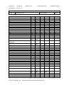
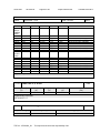
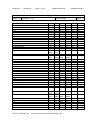
IEC 60950-1
Clause
Requirement + Test
T1 pin6 / T1 pin 14, 15, 16
T1 pin8 / T1 pin 11,12,13
T1 pin8 / T1 pin14,15,16
JPW1100KB1600F01
T1 pin1 / T1 pin 11, 12,13
T1 pin1 / T1 pin 14, 15,16
T1 pin 2 / T1 pin11,12,13
T1 pin2 / T1 pin 14,15,16
T1 pin6 / T1 pin 11,12,13
T1 pin6 / T1 pin 14, 15, 16
T1 pin8 / T1 pin 11,12,13
T1 pin8 / T1 pin14,15,16
PSU pin1 / PSU pin3
PSU pin1 / PSU pin4
PSU pin2 / PSU pin3
PSU pin2 / PSU pin4
<E300305-A33-CB-2,
Amendment3>, 11CA37964
Model ; JPW1100KB1800F01
T1 pin1 / T1 pin 11, 12,13
T1 pin1 / T1 pin 14, 15,16
T1 pin 2 / T1 pin11,12,13
T1 pin2 / T1 pin 14,15,16
T1 pin6 / T1 pin 11,12,13
T1 pin6 / T1 pin 14, 15, 16
T1 pin8 / T1 pin 11,12,13
T1 pin8 / T1 pin14,15,16
PSU pin2 / PSU pin3
PSU pin2 / PSU pin4
Model ; JPW1100KB1900F01
T1 pin1 / T1 pin 11, 12,13
T1 pin1 / T1 pin 14, 15,16
T1 pin 2 / T1 pin11,12,13
T1 pin2 / T1 pin 14,15,16
T1 pin6 / T1 pin 11,12,13
T1 pin6 / T1 pin 14, 15, 16
T1 pin8 / T1 pin 11,12,13
T1 pin8 / T1 pin14,15,16
PSU pin1 / PSU pin3
PSU pin1 / PSU pin4
PSU pin2 / PSU pin3
PSU pin2 / PSU pin4
Model ; JPW1100KB2400F01
T1 pin1 / T1 pin 11, 12,13
T1 pin1 / T1 pin 14, 15,16
T1 pin 2 / T1 pin11,12,13
T1 pin2 / T1 pin 14,15,16
T1 pin6 / T1 pin 11,12,13
TRF No. : IEC60950_1B
Result - Remark
Verdict
420
610
625
370
435
455
530
410
415
595
620
375
375
375
375
N/A
304
353
370
183
188
189
197
298
300
350
368
183
183
183
183
N/A
7.1
7.1
7.1
7.1
7.1
7.1
7.1
7.1
7.1
7.1
7.1
5.92
5.92
5.92
5.92
N/A
8.0
8.0
8.0
8.0
8.0
8.0
8.0
8.0
8.0
8.0
8.0
6.0
6.0
6.0
6.0
N/A
7.8
7.8
7.8
7.8
7.8
7.8
7.8
7.8
7.8
7.8
7.8
5.92
5.92
5.92
5.92
N/A
8.0
8.0
8.0
8.0
8.0
8.0
8.0
8.0
8.0
8.0
8.0
6.0
6.0
6.0
6.0
N/A
N/A
370
435
440
510
400
410
565
580
365
365
N/A
370
440
435
515
405
425
565
590
365
365
365
365
N/A
370
450
440
530
390
N/A
180
183
183
193
298
298
356
377
179
177
N/A
180
183
183
193
304
307
365
387
178
177
177
178
N/A
181
187
185
200
291
7.1
7.1
7.1
7.1
7.1
7.1
7.1
7.1
5.92
5.92
7.1
7.1
7.1
7.1
7.1
7.1
7.1
7.1
5.92
5.92
5.92
5.92
7.1
7.1
7.1
7.1
7.1
8.0
8.0
8.0
8.0
8.0
8.0
8.0
8.0
6.0
6.0
8.0
8.0
8.0
8.0
8.0
8.0
8.0
8.0
6.0
6.0
6.0
6.0
8.0
8.0
8.0
8.0
8.0
7.8
7.8
7.8
7.8
7.8
7.8
7.8
7.8
5.92
5.92
7.8
7.8
7.8
7.8
7.8
7.8
7.8
7.8
5.92
5.92
5.92
5.92
7.8
7.8
7.8
7.8
7.8
8.0
8.0
8.0
8.0
8.0
8.0
8.0
8.0
6.0
6.0
8.0
8.0
8.0
8.0
8.0
8.0
8.0
8.0
6.0
6.0
6.0
6.0
8.0
8.0
8.0
8.0
8.0
This report issued under the responsibility of UL
Issue Date:
2012-09-24
Correction 2
2013-01-16
Page 11 of 11
Report Reference #
E300305-A33-CB-4
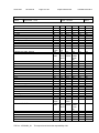
IEC 60950-1
Clause
Requirement + Test
T1 pin6 / T1 pin 14, 15, 16
T1 pin8 / T1 pin 11,12,13
T1 pin8 / T1 pin14,15,16
PSU pin1 / PSU pin3
PSU pin1 / PSU pin4
PSU pin2 / PSU pin3
PSU pin2 / PSU pin4
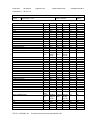
<E300305-A33-CB-4,
Amendment1>For model ;
JPW1100KB4800Q01
T1 pin1 to T1 pin 11,12,13
T1 pin1 to T1 pin 14,15,16
T1 pin2 to T1 pin 11,12,13
T1 pin2 to T1 pin 14,15,16
T1 pin6 to T1 pin 11,12,13
T1 pin6 to T1 pin 14,15,16
T1 pin8 to T1 pin 11,12,13
T1 pin8 to T1 pin 14,15,16
PSU1 pin1 to PSU1 pin3
PSU1 pin1 to PSU1 pin4
PSU1 pin2 to PSU1 pin3
PSU1 pin2 to PSU1 pin4
supplementary information:
Result - Remark
Verdict
415
540
565
365
365
365
365
N/A
295
356
383
178
178
178
179
N/A
7.1
7.1
7.1
5.92
5.92
5.92
5.92
N/A
8.0
8.0
8.0
6..0
6.0
6.0
6.0
N/A
7.8
7.8
7.8
5.92
5.92
5.92
5.92
N/A
8.0
8.0
8.0
6.0
6.0
6.0
6.0
N/A
390
590
470
690
410
460
510
600
375
365
370
365
183
208
188
235
300
315
351
390
174
171
173
171
7.1
7.1
7.1
7.1
7.1
7.1
7.1
7.1
5.92
5.92
5.92
5.92
8.0
8.0
8.0
8.0
8.0
8.0
8.0
8.0
6.0
6.0
6.0
6.0
7.8
7.8
7.8
7.8
7.8
7.8
7.8
7.8
5.92
5.92
5.92
5.92
8.0
8.0
8.0
8.0
8.0
8.0
8.0
8.0
6.0
6.0
6.0
6.0
C.2
Loc.
TABLE: transformers
Tested
Working
insulation
voltage
peak /V
(2.10.2)
T1
Reinforced 690
(Primary to
Secondary)
Loc.
Tested insulation
Working
voltage
rms /V
(2.10.2)
Required
electric
strength
(5.2)
Required
clearance /
mm
(2.10.3)
Required
creepage
distance /
mm
(2.10.4)
7.8
390
3000Vac
7.1
Test
voltage / V
Measured Measured
clearance / creepage
mm
dist./mm
Pass
Required
distance
thr. insul.
(2.10.5)
min. 1
layers or
0.4 mm
thickness
Measured
distance
thr. insul /
mm;
number of
layers
Transformer type number
Enclosure - Miscellaneous ID
supplementary information:
Tested T1 ; 3025579001A,3025579002A,3025579003A,3025579004A,3025579005A Also complied with
clause 2.9.2 humidity test.
TRF No. : IEC60950_1B
This report issued under the responsibility of UL
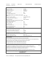
Ref. Certif. No.
DK-28210-A1-UL
IEC SYSTEM FOR MUTUAL RECOGNITION OF TEST
CERTIFICATES FOR ELECTRICAL EQUIPMENT
(IECEE) CB SCHEME
SYSTEME CEI D’ACCEPTATION MUTUELLE DE
CERTIFICATS D’ESSAIS DES EQUIPEMENTS
ELECTRIQUES (IECEE) METHODE OC
CB TEST CERTIFICATE CERTIFICAT D’ESSAI OC
Product
Produit
Switching Power Supply
Name and address of the applicant
Nom et adresse du demandeur
BRIDGEPOWER CORP
964 GOSAEK-DONG
GWONSEON-GU
SUWON-SI GYEONGGI-DO 441-813 KOREA
Name and address of the manufacturer
Nom et adresse du fabricant
BRIDGEPOWER CORP
964 GOSAEK-DONG
GWONSEON-GU
SUWON-SI GYEONGGI-DO 441-813 KOREA
Name and address of the factory
Nom et adresse de l’usine
BRIDGEPOWER CORP
964 GOSAEK-DONG
GWONSEON-GU
SUWON-SI GYEONGGI-DO 441-813
KOREA
Note: When more than one factory, please report on page 2
Note: Lorsque il y plus d'une usine, veuillez utiliser la 2ème page
Additional Information on page 2
Ratings and principal characteristics
Valeurs nominales et caractéristiques principales
See Page 2
Trademark (if any)
Marque de fabrique (si elle existe)
None
Type of Manufacturer's Testing Laboratories used
Type de programme du laboratoire d'essais
constructeur
TMP
Model / Type Ref.
Ref. De type
CENB1100********, JMW1100*********, JPW1100*********,
MENB1100********
See Page 2
Additional information (if necessary may also be
reported on page 2)
Les informations complémentaires (si nécessaire,,
peuvent être indiqués sur la 2ème page
Additional Information on page 2
A sample of the product was tested and found
to be in conformity with
Un échantillon de ce produit a été essayé et a été
considéré conforme à la
IEC 60950-1(ed.2), IEC 60950-1(ed.2);am1
As shown in the Test Report Ref. No. which forms part
of this Certificate
Comme indiqué dans le Rapport d’essais numéro de
référence qui constitue partie de ce Certificat
E300305-A33-CB-4 issued on 2012-11-27
This CB Test Certificate is issued by the National Certification Body
Ce Certificat d’essai OC est établi par l’Organisme National de Certification
UL (US), 333 Pfingsten Rd IL 60062, Northbrook, USA
UL (Demko), Borupvang 5A DK-2750 Ballerup, DENMARK
UL (JP), Marunouchi Trust Tower Main Building 6F, 1-8-3 Marunouchi, Chiyoda-ku, Tokyo 100-0005, JAPAN
UL (CA), 7 Underwriters Road, Toronto, M1R 3B4 Ontario, CANADA
For full legal ent
entity
n
names see www.ul.com/ncbnames
Date: 2012-11-27
Signature:
Original Issue Date: 2012-09-24
Jan-Erik
Erriikk Storgaard
1/2
Ref. Certif. No.
DK-28210-A1-UL
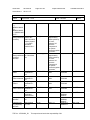
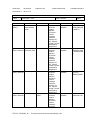
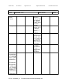
Model Details:
CENB1100 * ** ** * **
(b) (c) (d) (f) (e)
(b) means design revision changes, may be A to Z;
(c) means output voltages, may be 12, 13, 15, 16, 18,19, 24 or 48;
(d) means standards output cord options, may be 00 to 99;
(e) means custom options, may be 00 to 99 or AA to ZZ.
(f) means class type, maybe F(ClassI) or Q (ClassII) or N(ClassII)
JMW1100 * * ** ** *
(a) (b) (c) (d) (f)
**
(e)
(a) means custom options, may be A to Z;
(b) means design revision changes, may be A to Z;
(c) means output voltages, may be 12, 13, 15, 16, 18,19, 24 or 48;
(d) means standards output cord options, may be 00 to 99;
(e) means custom options, may be 00 to 99 or AA to ZZ.
(f) means class type, maybe F(ClassI) or Q (ClassII) or N(ClassII)
JPW1100 * * ** ** * **
(a) (b) (c) (d) (f) (e)
(a) means custom options, may be A to Z;
(b) means design revision changes, may be A to Z;
(c) means output voltages, may be 12, 13, 15, 16, 18,19, 24 or 48;
(d) means standards output cord options, may be 00 to 99;
(e) means custom options, may be 00 to 99 or AA to ZZ.
(f) means class type, maybe F(ClassI) or Q (ClassII) or N(ClassII)
MENB1100 * ** ** * **
(b) (c) (d) (f) (e)
(b) means design revision changes, may be A to Z;
(c) means output voltages, may be 12, 13, 15, 16, 18,19, 24 or 48;
(d) means standards output cord options, may be 00 to 99;
(e) means custom options, may be 00 to 99 or AA to ZZ.
(f) means class type, maybe F(ClassI) or Q (ClassII) or N(ClassII)
Factories:
WENDENG JEIL ELECTRONICS CO LTD
DONG SHOU GUANGZHOU LU KAIFA-QU
WENDENG-SHI SHANDONG
CHINA
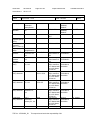
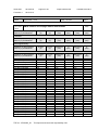
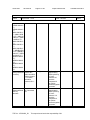
Ratings:
Input Rating: 100-240 Vac, 50-60 Hz, 2.0 A
Output Rating: 12.0 Vdc, 7.5 A or 13.0 Vdc, 6.92A or 15.0 Vdc, 6.4 A or 16.0Vdc, 6.0 A or 18.0 Vdc, 5.6 A or
19.0 Vdc, 5.2A or 24.0 Vdc, 4.2 A or 48.0 Vdc, 2.1A
Additional Information:
The original report was modified to include the following changes/additions: add alternate components, add electrical
output rating, add new models, add supplementary information in table and revise manufacturer declaration letter.
Additionally evaluated to EN 60950-1:2006/A11:2009/A1:2010/A12:2011; National Differences specified in the CB Test
Report.
Additional information (if necessary)
Information complémentaire (si nécessaire)
UL (US), 333 Pfingsten Rd IL 60062, Northbrook, USA
UL (Demko), Borupvang 5A DK-2750 Ballerup, DENMARK
UL (JP), Marunouchi Trust Tower Main Building 6F, 1-8-3 Marunouchi, Chiyoda-ku, Tokyo 100-0005, JAPAN
UL (CA), 7 Underwriters Road, Toronto, M1R 3B4 Ontario, CANADA
For full legal entity names see www.ul.com/ncbnames
Date: 2012-11-27
Original Issue Date: 2012-09-24
Signature:
Jan-Erik Storgaard
2/2
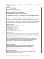
Issue Date:
2012-09-24
Amendment 1
2012-11-27
Page 1 of 44
Report Reference #
E300305-A33-CB-4
Test Report issued under
the responsibility of:
TEST REPORT
IEC 60950-1
Information technology equipment - Safety Part 1: General requirements
Report Reference No .................. :
E300305-A33-CB-4
Date of issue ................................. :
2012-09-24
Total number of pages .................. :
44
CB Testing Laboratory ............... :
UL Korea, Ltd.
Address ......................................... :
#808, Manhatan Building, 36-2 Yeouido-Dong, Yeongdeungpo-Gu,
Seoul 150-749, Korea
Applicant's name ........................ :
BRIDGEPOWER CORP
964 GOSAEK-DONG
GWONSEON-GU
SUWON-SI GYEONGGI-DO 441-813 KOREA
Address ......................................... :
Test specification:
Standard ........................................ :
IEC 60950-1:2005 (2nd Edition); Am 1:2009
Test procedure .............................. :
CB Scheme
Non-standard test method ............ :
N/A
Test Report Form No. ................. :
IEC60950_1B
Test Report Form originator .......... :
SGS Fimko Ltd
Master TRF ................................... :
2010-04
Copyright © 2010 IEC System for Conformity Testing and Certification of Electrical Equipment
(IECEE), Geneva, Switzerland. All rights reserved.
This publication may be reproduced in whole or in part for non-commercial purposes as long as the IECEE is
acknowledged as copyright owner and source of the material. IECEE takes no responsibility for and will not
assume liability for damages resulting from the reader's interpretation of the reproduced material due to its
placement and context.
If this test Report is used by non-IECEE members, the IECEE/IEC logo and the reference to the CB Scheme
procedure shall be removed.
This report is not valid as a CB Test Report unless signed by an approved CB Testing Laboratory and
appended to a CB Test Certificate issued by an NCB in accordance with IECEE 02.
TRF No. : IEC60950_1B
This report issued under the responsibility of UL
Issue Date:
2012-09-24
Amendment 1
2012-11-27
Page 2 of 44
Report Reference #
E300305-A33-CB-4
Test item description .................. :
Switching Power Supply
Trade Mark .................................... :
None
Manufacturer ................................. :
BRIDGEPOWER CORP
964 GOSAEK-DONG
GWONSEON-GU
SUWON-SI GYEONGGI-DO 441-813 KOREA
Model/Type reference ................... :
Models CENB1100********, MENB1100********, and
JMW1100********* and JPW1100*********
Ratings .......................................... :
Input Rating: 100-240 Vac, 50-60 Hz, 2.0 A
Output Rating: 12.0 Vdc, 7.5 A or
13.0 Vdc, 6.92A or
15.0 Vdc, 6.4 A or
16.0Vdc, 6.0 A or
18.0 Vdc, 5.6 A or
19.0 Vdc, 5.2A or
24.0 Vdc, 4.2 A or
48.0 Vdc, 2.1A
TRF No. : IEC60950_1B
This report issued under the responsibility of UL
Issue Date:
2012-09-24
Amendment 1
2012-11-27
Page 3 of 44
Report Reference #
E300305-A33-CB-4
Testing procedure and testing location:
[ ]
CB Testing Laboratory
Testing location / address .............. :
[ ]
Associated CB Test Laboratory
Testing location / address .............. :
Tested by (name + signature) ....... :
Approved by (name + signature) ... :
[x]
[ ]
Testing Procedure: TMP
Tested by (name + signature) ....... :
InYoung Hwang
Approved by (+ signature) ............. :
Frederic Won
Testing location / address .............. :
BRIDGEPOWER CORP / 964 GOSAEK-DONG
GWONSEON-GU SUWON-SI GYEONGGI-DO 441-813
KOREA
Testing Procedure: WMT
Tested by (name + signature) ....... :
Witnessed by (+ signature) ............ :
Approved by (+ signature) ............. :
Testing location / address .............. :
[ ]
Testing Procedure: SMT
Tested by (name + signature) ....... :
Approved by (+ signature) ............. :
Supervised by (+ signature) .......... :
Testing location / address .............. :
[ ]
Testing Procedure: RMT
Tested by (name + signature) ....... :
Approved by (+ signature) ............. :
Supervised by (+ signature) .......... :
Testing location / address .............. :
List of Attachments
National Differences (0 pages)
Enclosures (34 pages)
Summary Of Testing
Unless otherwise indicated, all tests were conducted at BRIDGEPOWER CORP / 964 GOSAEK-DONG
GWONSEON-GU SUWON-SI GYEONGGI-DO 441-813 KOREA.
Tests performed (name of test and test clause)
Testing location / Comments
End Product Reference Page
TRF No. : IEC60950_1B
This report issued under the responsibility of UL
Issue Date:
2012-09-24
Amendment 1
2012-11-27
Page 4 of 44
Report Reference #
E300305-A33-CB-4
General Guidelines
Guide Information Page - Maximum Output Voltage,
Current, and Volt Ampere Measurement (1.2.2.1)
Input: Single-Phase (1.6.2)
SELV Reliability Test Including Hazardous Voltage
Measurements (2.2.2, 2.2.3, 2.2.4, Part 22 6.1)
Determination of Working Voltage; Working Voltage
Measurement (2.10.2)
Thin Sheet Material (2.10.5.9, 2.10.5.10, 2.10.5.6)
Transformer and Wire /Insulation Electric Strength
(2.10.5.13)
Stress Relief (4.2.7, 4.2.1)
Heating (4.5.1, 1.4.12, 1.4.13)
Electric Strength (5.2.2)
Transformer Abnormal Operation (5.3.3, 5.3.7b, Annex
C.1)
Summary of Compliance with National Differences:
Countries outside the CB Scheme membership may also accept this report.
List of countries addressed: AT, BE, CA, CH, CN, CZ, DE, DK, ES, EU, FI, FR, GB, GR, HU, IE, IL, IT, JP,
KR, NL, NO, PL, PT, SE, SG, SI, SK, US
The product fulfills the requirements of: N/A
Copy of Marking Plate - Refer to Enclosure titled Marking Plate for copy.
TRF No. : IEC60950_1B
This report issued under the responsibility of UL
Issue Date:
2012-09-24
Amendment 1
2012-11-27
Page 5 of 44
Report Reference #
E300305-A33-CB-4
Test item particulars :
Equipment mobility ...............................................:
movable
Connection to the mains ......................................:
pluggable A
Operating condition ..............................................:
continuous
Access location ....................................................:
N/A
Over voltage category (OVC) ..............................:
OVC II
Mains supply tolerance (%) or absolute mains supply
values ...................................................................:
+10%, -10%
Tested for IT power systems ...............................:
Yes(for Norway only)
IT testing, phase-phase voltage (V) .....................:
230 Vac
Class of equipment ..............................................:
Class I (earthed)
Considered current rating of protective device as part
of the building installation (A) ...............................:
2.0
Pollution degree (PD) ...........................................:
PD 2
IP protection class ................................................:
IP X0
Altitude of operation (m) .......................................:
up to 5000m
Altitude of test laboratory (m) ...............................:
N/A
Mass of equipment (kg) .......................................:
0.7
Possible test case verdicts:
- test case does not apply to the test object ........... :
N/A
- test object does meet the requirement ................. :
P(Pass)
- test object does not meet the requirement ........... :
F(Fail)
Testing:
Date(s) of receipt of test item ...............................:
2012-10-15
Date(s) of Performance of tests ...........................:
2012-10-23 to 2012-11-19
General remarks:
The test results presented in this report relate only to the object tested.
This report shall not be reproduced, except in full, without the written approval of the testing laboratory.
"(see Enclosure #)" refers to additional information appended to the report.
"(see appended table)" refers to a table appended to the report.
Throughout this report a point is used as the decimal separator.
Manufacturer's Declaration per Sub Clause 6.25 of IECEE 02:
Yes
The application for obtaining a CB Test Certificate includes more than one factory and a
declaration form the Manufacturer stating that the sample(s) submitted for evaluation is (are)
representative of the products from each factory has been provided ......
When differences exist, they shall be identified in the General Product Information section.
Name and address of Factory(ies):
TRF No. : IEC60950_1B
BRIDGEPOWER CORP
964 GOSAEK-DONG
GWONSEON-GU
This report issued under the responsibility of UL
Issue Date:
2012-09-24
Amendment 1
2012-11-27
Page 6 of 44
Report Reference #
E300305-A33-CB-4
SUWON-SI GYEONGGI-DO 441-813 KOREA
WENDENG JEIL ELECTRONICS CO LTD
DONG SHOU GUANGZHOU LU
KAIFA-QU
WENDENG-SHI SHANDONG CHINA
GENERAL PRODUCT INFORMATION:
Report Summary
The original report was modified on 2012-11-27 to include the following changes/additions:
E300305-A33-CB-4, Amendment 1
- Alternate appliance inlet type SS-120A,RF-180 by Rong Feng Industrial Co., Ltd
- Alternate linefilter 3025671B
- Alternate Y-Capacitor(CY1,CY2) type SE or SB , 250V, maximum 1500pF by Success Electronics Co., Ltd
- Alternate Y-Capacitor(CY1,CY2) type KX or KY , 250V, maximum 1500pF by Murata Mfg.Co., Ltd
- Alternate Y-Capacitor(CY3,CY4) type SE or SB , 250V, maximum 1000pF by Success Electronics Co., Ltd
- Alternate Y-Capacitor(CY3,CY4) type KX or KY , 250V, maximum 1000pF by Murata Mfg.Co., Ltd
- Add electrical output rating ; 48Vdc/2.1A (transformer type 3025579005A ) ; JPW1100**48*****,
JMW1100**48*****, CENB1100*48*****,MENB1100*48*****
- Add insulator sheet and shield.
- Alternate ClassII type ; JPW1100******Q***, JMW1100******Q**,
CENB1100*****Q**,MENB1100*****Q**,JPW1100******N***, JMW1100******N**,
CENB1100*****N**,MENB1100*****N**
- Add supplementary information in table 5.2, table 2.10.3 and 2.10.4 , optical isolator table(1,5,1),table C.2
- Revise manufacturer declaration letter
Product Description
Switching Power Supply (AC/DC adapter), consists of electronic components mounted on PWB, a switching
transformer and electronic components mounted on PWB, housed with a plastic enclosure.
Model Differences
Models CENB1100********, MENB1100********, and JMW1100********* and JPW1100********* (Where * may
be alphanumeric, "for marketing purpose and no impact safety related critical components and
constructions")
Models CENB1100********, MENB1100********, and JMW1100********* are identical to JPW1100*********,
except model designations as follows;
Nomenclature
JPW1100 * * ** ** * **
(a) (b) (c) (d) (f) (e)
or JMW1100 * * ** ** *
**
(a) (b) (c) (d) (f) (e)
or CENB1100 * ** **
* **
(b) (c) (d) (f) (e)
TRF No. : IEC60950_1B
This report issued under the responsibility of UL
Issue Date:
2012-09-24
Amendment 1
2012-11-27
Page 7 of 44
Report Reference #
E300305-A33-CB-4
or MENB1100 * ** ** * **
(b) (c) (d) (f) (e)
(a) means custom options, may be A to Z;
(b) means design revision changes, may be A to Z;
(c) means output voltages, may be 12, 13, 15, 16, 18,19, 24 or 48;
(d) means standards output cord options, may be 00 to 99;
(e) means custom options, may be 00 to 99 or AA to ZZ.
(f) means class type, maybe F(ClassI) or Q (ClassII) or N(ClassII)
The marked models as 12, 13, 15, 16, 18, 19 , 24 and 48 on (c) nomenclature are identical individually,
except model designations, output ratings, transformers and secondary circuits.
The Models JPW1100**13*****, JPW1100**16*****, CENB1100*13*****,CENB1100*16*****,
JMW1100**13*****, JMW1100**16*****, MENB1100*13*****, and MENB1100*16***** are identical to Model
JPW1100**12***** except for model designation, output ratings, transformers and secondary circuits.
The model JPW1100**19*****, CENB1100*19*****, JMW1100**19*****, MENB1100*19***** are identical to
JPW1100**12***** except for model designation, output ratings, transformers and secondary circuits.
Additional Information
Maximum Normal Load Condition: Rated Output Currents
JPW1100KA1200F01: 12.0 Vdc, 7.5 A;
JPW1100KA1500F01: 15.0 Vdc, 6.4 A;
JPW1100KA1800F01: 18.0 Vdc, 5.6 A;
JPW1100KA2400F01: 24.0 Vdc, 4.2 A.
This equipment is not provided with user's manual.
Procedure Deviation:
Argentina*, Australia / New Zealand, Austria**, Belgium**, China, Czech Republic**, Denmark, Finland,
France**, Germany, Greece**, Group, Hungary*, India*, Ireland*, Israel*, Italy*, Japan*, Kenya*, Korea,
Malaysia*, Netherlands**, Norway, Poland*, Portugal*, Singapore*, Slovakia**, Slovenia*, Spain*, Sweden,
Switzerland**, and United Kingdom.
* - No National Differences Declared, ** - Only Group Differences.
Before placing the products in the different countries, the manufacturer has to guarantee that:
1. Operating instructions and warnings are written in an accepted language of the certain country.
2. The equipment is in compliance with the national standards of the certain country.
E300305-A33-CB-3, Reissue
- Added Thermal Fuse (Seki Controls Co., Ltd., Type ST-22) in critical component list.
E300305-A33-CB-4, Reissue
- Upgrade report from IEC 60950-1 2nd edition to IEC 60950-1 2nd edition, Amendment1
- Altitude of operation is up to 2000m to up to 5000m refer to IEC 60664-1 table A.2
- Humidity test was conducted at 40 degreeC, 95% , 120hours for China Deviation.
- National Difference for China is revised.
- Tma is changed from 30 degreeC to 35 degreeC
E300305-A33-CB-4, Correction1
- Add optical isolator certification information under mark of conformity section due to missing
- Add bobbin's manufacturer name due to missing
TRF No. : IEC60950_1B
This report issued under the responsibility of UL
Issue Date:
2012-09-24
Amendment 1
2012-11-27
Page 8 of 44
Report Reference #
E300305-A33-CB-4
- Correct optical isolator CR,CL from "thermal cycling conducted " to measured CR, CP in table 2.10.2 ,
2.10.3 and 2.10.4 due to typo error
- Delete Enclosure type HN-1064W(+) in critical component list due to typo error
- Correct electric strength table due to typo error
E300305-A33-CB-4, Amendment 1(12CA56785)
- Alternate appliance inlet type SS-120A,RF-180 by Rong Feng Industrial Co., Ltd
- Alternate linefilter 3025671B
- Alternate Y-Capacitor(CY1,CY2) type SE or SB , 250V, maximum 1500pF by Success Electronics Co., Ltd
- Alternate Y-Capacitor(CY1,CY2) type KX or KY , 250V, maximum 1500pF by Murata Mfg.Co., Ltd
- Alternate Y-Capacitor(CY3,CY4) type SE or SB , 250V, maximum 1000pF by Success Electronics Co., Ltd
- Alternate Y-Capacitor(CY3,CY4) type KX or KY , 250V, maximum 1000pF by Murata Mfg.Co., Ltd
- Add electrical output rating ; 48Vdc/2.1A (transformer type 3025579005A ) ; JPW1100**48*****,
JMW1100**48*****, CENB1100*48*****,MENB1100*48*****
- Add insulator sheet and shield.
- Alternate ClassII type ; JPW1100******Q***, JMW1100******Q**,
CENB1100*****Q**,MENB1100*****Q**,JPW1100******N***, JMW1100******N**,
CENB1100*****N**,MENB1100*****N**
- Add supplementary information in table 5.2, table 2.10.3 and 2.10.4 , optical isolator table(1,5,1),table C.2
- Revise manufacturer declaration letter
Technical Considerations
The product was submitted and evaluated for use at the maximum ambient temperature (Tma)
permitted by the manufacturer’s specification of: 35
The means of connection to the mains supply is: Pluggable A, Detachable Power Supply Cord,
The product is intended for use on the following power systems: TN and IT (for Norway only),
The equipment disconnect device is considered to be: Appliance Inlet
The product was investigated to the following additional standards: EN 60950-1:2006 + A11:2009 +
A1:2010 + A12:2011 (which includes all European national differences, including those specified in
this test report).
Abbreviations used in the report:
- normal condition ............................................N.C.
:
- single fault condition ....................................... S.F.C
:
- operational insulation .....................................OP
:
- basic insulation .............................................. BI
:
- basic insulation between parts of opposite
polarity:
- supplementary insulation ............................... SI
:
BOP
- double insulation ............................................DI
:
- reinforced insulation ...................................... RI
:
Indicate used abbreviations (if any)
TRF No. : IEC60950_1B
This report issued under the responsibility of UL
Issue Date:
2012-09-24
Amendment 1
2012-11-27
Page 9 of 44
Report Reference #
E300305-A33-CB-4
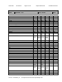
IEC 60950-1
Clause
Requirement + Test
1.7.1.2
Model identification or type reference ......:
Result - Remark
Verdict
Pass
CENB1100********,
MENB1100********, and
JMW1100********* and
JPW1100*********
4.2.7
Pass
Stress relief test
TRF No. : IEC60950_1B
No indication of
shrinkage or distortion on
enclosures due to the stress
relief test 100 degree C/7 h.
This report issued under the responsibility of UL
Issue Date:
2012-09-24
Amendment 1
2012-11-27
Page 10 of 44
Report Reference #
E300305-A33-CB-4
IEC 60950-1
Clause
Requirement + Test
1.5.1
TABLE: list of critical components
object/part or
Description
Enclosure
(Electrical/Mechi
cal/Fire)
Result - Remark
type/model
manufacturer/
trademark
Sabic Innovative 940(f1)
Plastics B V,
Sabic Innovative
Plastics Japan L
L C or Sabic
Innovative
Plastics US L L
C
Enclosure(Electri Cheil Industries
cal/Mechanical/F Inc. Chemicals
ire) Alternate
Div.
HN-1064(+)
Appliance Inlet
Rong Feng
Industrial Co.,
Ltd.
Rich Bay Co.,
Ltd.
Rong Feng
Industrial Co.,
Ltd.
Littelfuse
WickmannWerke GmbH
Save Fusetech
Inc.
SS-120-PCB
Appliance Inlet
Alternate
Appliance Inlet
Alternate
Fuse (F1)
(Optional)
Fuse (F1)
(Optional)
Alternate
Thermal Fuse
(F1) (Optional)
Alternate
Fuse (F2)
Fuse (F2)
Alternate
Pass
technical data
standard (Edition mark(s) of
1
or year)
conformity )
UL94, UL746C
USR(E45329), -
V-0 Overall
approximately
149.8 by 86.6 by
51.0 mm,
minimum 2.0
mm thick.
Composed of
two pieces,
secured together
by screws. RTI;
120 degreeC
V-0 Overall
UL94, UL746C
approximately
149.8 by 86.6 by
51.0 mm,
minimum 2.0
mm thick.
Composed of
two pieces,
secured together
by screws. RTI;
130 degreeC
Minimum 10A,
UL498,
250V.
IEC60320
USR(E115797), -
USR, SEMKO
Minimum 10A,
250V.
Minimum 15A or
10A, 250V.
UL498,
IEC60320
UL498,
IEC60320
USR, VDE
392
250V, 3.15A
USR, VDE
SS-5
250V, 3.15A
Seki Controls
Co., Ltd.
ST-22
250V, 7A
UL248,
VDE0820,
EN60127
UL248,
VDE0820,
EN60127
EN60730-1,
VDE0631-1
Littelfuse
WickmannWerke GmbH
Save Fusetech
Inc.
392
250V, 3.15A
USR, VDE
SS-5
250V, 3.15A
UL248,
VDE0820,
EN60127
UL248,
VDE0820,
TRF No. : IEC60950_1B
R-30190
Verdict
SS-120A
This report issued under the responsibility of UL
USR, VDE
USR, VDE
USR, VDE
USR, VDE
Issue Date:
2012-09-24
Amendment 1
2012-11-27
Page 11 of 44
Report Reference #
E300305-A33-CB-4
IEC 60950-1
Clause
Requirement + Test
Result - Remark
Thermister (TH1) Various
Various
Discharging
Various
Resistors
(RP111, RP112)
Varistor (TNR1) Amotech Co.,
Optional
Ltd.
Various
Varistor (TNR1)
Optional)
Alternate
X-Capacitor
(CX1)
Success
Electronics Co.,
Ltd.
Carli Electronics
Co., Ltd.
SVR14D471K
X-Capacitor
(CX1) Alternate
Iskra Mis D D
KNB 1530 or
1562 or 1563
X-Capacitor
(CX1) Alternate
Pilkor Electronics PCX2 335M or
Co., Ltd.
PCX2 337
X-Capacitor
(CX1) Alternate
Okaya Electric
Industries Co.,
Ltd.
X-Capacitor
(CX1) Alternate
Sun Il
436D
Electronics
Industry Co., Ltd.
Line Filter (LF1)
Bridgepower
Corp. or
Wendeng Jeil
Electronics Co.,
Ltd.
TRF No. : IEC60950_1B
INR14D471
MPX
LE
3025560
NTC, 5ohm at
25°C.
510Kohm 1/8W
(Line to Line)
Minimum 470V
Overall 14 mm.
(Line to Line)
Minimum 470V
Overall 14 mm.
(Line to Line)
250V, maximum
0.47uF. Marked
with X1 or X2.
Meets
IEC60384-14.
(Line to Line)
250V, maximum
0.47uF. Marked
with X1 or X2.
Meets
IEC60384-14.
(Line to Line)
250V, maximum
0.47uF. Marked
with X1 or X2.
Meets
IEC60384-14.
(Line to Line)
250V, maximum
.0.47uF. Marked
with X1 or X2.
Meets
IEC60384-14.
(Line to Line)
250V, maximum
.0.47uF. Marked
with X1 or X2.
Meets
IEC60384-14.
Core: Ferrite. 24
by 24 mm. Coils:
Polyurethane
Wire, minimum
130°C Bobbin:
(QMFZ2),
EN60127
Tested in
equipment.
Tested in
equipment.
Verdict
-, -, -
UL1449,
IEC60384-14
USR, VDE
UL1449,
IEC60384-14
USR, VDE
UL1414,
IEC384-14,
EN132400
USR, FIMKO
NEMKO SEMKO
UL1414,
IEC384-14,
EN132400
USR, FIMKO,
VDE
UL1414,
IEC384-14,
EN132400
USR, DEMKO
FIMKO
UL1414,
IEC384-14,
EN132400
USR, SEMKO
UL1414,
IEC384-14,
EN132400
USR, FIMKO
Tested in
equipment.
-, -
This report issued under the responsibility of UL
Issue Date:
2012-09-24
Amendment 1
2012-11-27
Page 12 of 44
Report Reference #
E300305-A33-CB-4
IEC 60950-1
Clause
Requirement + Test
Result - Remark
Line Filter (LP1,
LP2, LP4, LP5)
Bridgepower
Corp. or
Wendeng Jeil
Electronics Co.,
Ltd.
6872250
PFC Coil for
12V, 18V, 24V
output
Bridgepower
Corp. or
Wendeng Jeil
Electronics Co.,
Ltd.
Part No.:
3025578
PFC Coil for 15V Bridgepower
output
Corp. or
Wendeng Jeil
Electronics Co.,
Ltd.
Part No.:
3025578001
Y-Capacitors
(CY1, CY2)
Success
Electronics Co.,
Ltd.
SE or SB
Y-Capacitors
(CY1, CY2) Alternate
Murata Mfg. Co., KX or KY
Ltd.
TRF No. : IEC60950_1B
SUMITOMO
BAKELITE CO
LTD, type;PM9820, V-0,
150°C.
Core: Ferrite
13.7 by 8 mm.
Coils:
Polyurethane
Wire, minimum
130°C Insulation
Tubing/Sleeving:
FEP, PTFE,
PVC, TFE,
Neoprene,
Polyimide or
VW-1; 130°C.
Core: Ferrite 26
by 25 mm Coils:
Polyurethane
Wire, minimum
130°C Bobbin:
(QMFZ2),
SUMITOMO
BAKELITE CO
LTD, type;PM9820, V-0,
150°C.
Core: Ferrite 26
by 25 mm Coils:
Polyurethane
Wire, minimum
130°C Bobbin:
(QMFZ2),
SUMITOMO
BAKELITE CO
LTD, type;PM9820, V-0,
150°C.
(Line to Ground)
250V, maximum
2200pF. Marked
with Y1 or Y2.
Meets
IEC60384-14.
(Line to Ground)
250V, maximum
2200pF. Marked
Verdict
Tested in
equipment.
-, -
Tested in
equipment.
-, -
Tested in
equipment.
-, -
UL1414,
IEC60384-14,
EN132400
USR, FIMKO
UL1414,
IEC60384-14,
EN132400
USR, FIMKO
This report issued under the responsibility of UL
Issue Date:
2012-09-24
Amendment 1
2012-11-27
Page 13 of 44
Report Reference #
E300305-A33-CB-4
IEC 60950-1
Clause
Requirement + Test
Result - Remark
Y-Capacitors
(CY1, CY2) Alternate
TDK-EPC Corp.
CD or CS
Bridge Diode
(BD1)
Bridging
Capacitors (CY3,
CY4)
Various
Various
Success
Electronics Co.,
Ltd.
SE or SB
Bridging
Murata Mfg. Co., KX or KY
Capacitors (CY3, Ltd.
CY4) Alternate
Bridging
TDK-EPC Corp.
Capacitors (CY3,
CY4) Alternate
CD or CS
Electrolytic
Capacitor (CP1)
Various
Various
FET (QP1)
Various
Various
FET (QP2)
Various
Various
FET (QP3)
Various
Various
Switching IC
(UP1)
Various
Various
TRF No. : IEC60950_1B
with Y1 or Y2.
Meets
IEC60384-14.
(Line to Ground)
250V, maximum
2200pF. Marked
with Y1 or Y2.
Meets
IEC60384-14.
Minimum 600V,
maximum 10A.
(Primary to
Secondary)
250V, maximum
1500pF. Marked
with Y1 or Y2.
Meets
IEC60384-14.
(Primary to
Secondary)
250V, maximum
1500pF. Marked
with Y1 or Y2.
Meets
IEC60384-14.
(Primary to
Secondary)
250V, maximum
1500pF. Marked
with Y1 or Y2.
Meets
IEC60384-14.
Minimum 400V,
maximum
150uF, minimum
105°C.
550V, 18A
Secured to Heat
Sink (HS1) by
screw.
SMD type. 60V,
115mA
800V, 11A or
13A Secured to
Heat Sink (HS1)
by screw.
Maximum 22V,
0.03A.
Verdict
UL1414,
IEC60384-14,
EN132400
USR, VDE
Tested in
equipment.
UL1414,
IEC60384-14,
EN132400
-, -
UL1414,
IEC60384-14,
EN132400
USR, FIMKO
UL1414,
IEC60384-14,
EN132400
USR, VDE
Tested in
equipment.
-, -
Tested in
equipment.
-, -
Tested in
equipment.
Tested in
equipment.
-, -
Tested in
equipment.
-, -
This report issued under the responsibility of UL
USR, FIMKO
-, -
Issue Date:
2012-09-24
Amendment 1
2012-11-27
Page 14 of 44
Report Reference #
E300305-A33-CB-4
IEC 60950-1
Clause
Requirement + Test
Result - Remark
Switching IC
Various
(UP2)
Main
Bridgepower
Transformer (T1) Corp. or
Wendeng Jeil
Electronics Co.,
Ltd.
Various
Optical Isolator
(PSU1)
TCET1103(G)
Vishay
Semiconductor
GmbH
JEC(B) (Part
No.:
3025579011 for
12V output; Part
No.:
3025579012 for
15V output; Part
No.:
3025579013 for
18V output; Part
No.:
3025579014 for
24V output)
Optical Isolator
Cosmo
KP1010
(PSU1) Alternate Electronics Corp.
TRF No. : IEC60950_1B
Maximum 18V,
5.0mA.
Class B. Core:
Ferrite 40 by 42
mm. Coils:
Polyurethane
Wire, minimum
130°C TIWW:
Furukawa
Electric Co., Ltd.,
TEX-E, 130°C
Bobbin:
SUMITOMO
BAKELITE CO
LTD, type;PM9820 (QMFZ2),
V-0, 150°C,
Insulation tape,
DUCK SUNG
HITECH CO
LTD, DUCK
SUNG HITECH
CO LTD, Cat No.
220-8 or DTS204
Double
Protection.
Isolation
5000Vac.
DTI;0.4mm,
External
Creepage,
Clearance
minimum 6.0
mm. Thermal
Cycling Test was
conducted by
BridgePower.
Double
Protection.
Isolation
5000Vac.
DTI;0.4mm,
External
Creepage,
Clearance
minimum 6.5
mm. Thermal
Verdict
Tested in
equipment.
UL1446
-, -
UL1577,
EN60950
USR, BSI
(7402),CQC(090
01038077)
UL1577,
EN60950
USR,
SEMKO(101643
3),FIMKO(22498
6)
This report issued under the responsibility of UL
USR, -
Issue Date:
2012-09-24
Amendment 1
2012-11-27
Page 15 of 44
Report Reference #
E300305-A33-CB-4
IEC 60950-1
Clause
Requirement + Test
Result - Remark
Optical Isolator
Sharp Corp.
(PSU1) Alternate
PC123
Optical Isolator
Kodenshi Corp.
(PSU1) Alternate
PC-17K or PC17K1C
Zener Diodes
(DP14, ZD3,
DP6)
Insulation Sheet
(Around T1
Primary)
Various
Various
Various
Various
Heat Sink (HS1)
(Primary)
Various
Various
TRF No. : IEC60950_1B
Cycling Test was
conducted by
BridgePower.
Double
Protection.
Isolation
5000Vac.
DTI;0.4mm,
External
Creepage,
Clearance
minimum 7.0
mm. Thermal
Cycling Test was
conducted by
BridgePower.
Double
Protection.
Isolation
5000Vac.
DTI;0.4mm,
External
Creepage,
Clearance
minimum 7.0
mm. Thermal
Cycling Test was
conducted by
BridgePower.
18V, 0.5W
Verdict
UL1577,
EN60950
USR, SEMKO(
9216212),
NEMKO(135957
)
UL1577,
EN60950
USR, Semko(
9805214/01-04)
Tested in
equipment.
-, -
One piece. V-0, UL94, UL746
minimum 125°C.
Overall
approximately 42
by 42 mm,
minimum 0.4
mm thick.
Metal. Overall
Tested in
approximately.
equipment.
128.7 by 36 mm,
2 mm thick.
Wound by
Polyester Film
Tape, (OANZ2),
minimum 130°C,
minimum three
This report issued under the responsibility of UL
USR, -
-, -
Issue Date:
2012-09-24
Amendment 1
2012-11-27
Page 16 of 44
Report Reference #
E300305-A33-CB-4
IEC 60950-1
Clause
Requirement + Test
Result - Remark
Heat Sink (HS2)
(Secondary)
Various
Various
Heat Sink (HS3)
(Around
BD1)_optional
Various
Various
Printed Wiring
Board (PWB)
Protective
Bonding
Conductor
Various
Various
Various
Various
Bonding Glue
Various
Various
Output Cable
Various
Various
TRF No. : IEC60950_1B
turns in primary
side.
Metal. Overall
approximately.
69.3 by 36 mm,
3 mm thick.
Wound by
Polyester Film
Tape, (OANZ2),
minimum 130°C,
minimum three
turns in primary
side.
Metal. Overall
approximately 40
by 30 mm, 1.5
mm thick.
Wound by
Polyester Film
Tape, (OANZ2),
minimum 130°C,
minimum 1 turns
in primary side.
Minimum V-1,
130°C.
Mechanically
clamped or
secured on PWB
from Appliance
Inlet. Minimum
18 AWG, Greenand-Yellow
Insulation.
Minimum V-2,
minimum 100°C
for additional
secureness of
Internal
Conductor.
For use of
External
Interconnection),
Style No. 2464
or 1777, VW-1 or
FT-1, minimum
300V, 80°C, 18
AWG, maximum
3.05 m long.
Tested in
equipment.
Verdict
-, -
-, -
UL796
USR, -
UL758
USR, -
UL94, UL746
USR, -
UL758
USR, -
This report issued under the responsibility of UL
Issue Date:
2012-09-24
Amendment 1
2012-11-27
Page 17 of 44
Report Reference #
E300305-A33-CB-4
IEC 60950-1
Clause
Requirement + Test
Result - Remark
Nameplate Label Various
Various
For Models
JPW1100*B12**
***,JPW1100*B1
3*****,JPW1100*
B15*****,JPW11
00*B16*****,
JPW1100*B18**
***,
JPW1100*B19**
***,
JPW1100*B24**
***,JPW1100*B4
8*****,CENB110
0A12*****,CENB
1100A13*****,CE
NB1100A15*****,
CENB1100A16**
***,
CENB1100A18**
***,
CENB1100A19**
***,
CENB1100A24**
***,CENB1100A
48*****,JMW110
0*B12*****,JMW
1100*B13*****,J
MW1100*B15***
**,JMW1100*B1
6*****,
JMW1100*B18**
***,
JMW1100*B19**
***,
JMW1100*B24**
***,JMW1100*B4
8*****,MENB110
0A12*****,MENB
1100A13*****,M
ENB1100A15****
*,MENB1100A16
*****,
-
TRF No. : IEC60950_1B
Suitable for use
on surface of
Polycarbonate
(PC) with
maximum 60°C
surface
temperature.
-
Verdict
UL969
USR, -
-
-, -
This report issued under the responsibility of UL
Issue Date:
2012-09-24
Amendment 1
2012-11-27
Page 18 of 44
Report Reference #
E300305-A33-CB-4
IEC 60950-1
Clause
Requirement + Test
Result - Remark
MENB1100A18*
****,
MENB1100A19*
*F**,
MENB1100A24*
****,MENB1100A
48**F**
Enclosure
Sabic Innovative 940(f1)
(Electrical/Mecha Plastics B V,
nical/Fire)
Sabic Innovative
Plastics Japan L
L C or Sabic
Innovative
Plastics US L L
C
V-0 Overall
approximately
149.8 by 86.6 by
51.0 mm,
minimum 2.0
mm thick.
Composed of
two pieces.
Secured together
by screws.
V-0 Overall
approximately
149.8 by 86.6 by
51.0 mm,
minimum 2.0
mm thick.
Composed of
two pieces.
Secured together
by screws.
Minimum 10A,
250V.
UL94, UL746C
UL, -
UL94, UL746C
UL, -
UL498,
IEC60320
UL, SEMKO
R-30190
Minimum 10A,
250V.
UL498,
IEC60320
UL, VDE
RF-180
Minimum 2.5A,
250V.
UL498,
IEC60320
UL, VDE
SS-120A
Minimum 10A,
250V.
UL498,
IEC60320
UL, VDE
392
250V, 3.15A
UL248,
VDE0820,
EN60127
UL248,
VDE0820,
EN60127
EN60730-1,
VDE0631-1
UL, VDE
Enclosure
Cheil Industries
(Electrical/Mecha Inc. Chemicals
nical/Fire)
Div.
Alternate
HN-1064(+)
Appliance Inlet
Class I
Rong Feng
Industrial Co.,
Ltd.
Appliance Inlet
Rich Bay
Class I Alternate Industrial Co.,
Ltd.
Appliance Inlet – Rong Feng
Class II
Industrial Co.,
Ltd.
Appliance Inlet– Rong Feng
Class II Alternate Industrial Co.,
Ltd.
Fuse (F1)
Littelfuse
WickmannWerke GmbH
Fuse (F1)
Save Fusetech
Alternate
Inc.
SS-120-PCB
SS-5
250V, 3.15A
Thermal Fuse
(F1) (Optional)
Alternate
ST-22
250V, 7A
Seki Controls
Co., Ltd.
TRF No. : IEC60950_1B
Verdict
This report issued under the responsibility of UL
UL, VDE
USR, VDE
Issue Date:
2012-09-24
Amendment 1
2012-11-27
Page 19 of 44
Report Reference #
E300305-A33-CB-4
IEC 60950-1
Clause
Requirement + Test
Fuse (F2) -
392
250V, 3.15A
SS-5
250V, 3.15A
Thermistor (TH1) Various
Various
Discharging
Resistors (RP30,
RP31)
Discharging
Resistors
(RP111, RP112)
Discharging IC
(UP3)
Varistor (TNR1)
Optional
Various
Various
NTC, 5ohm at
25°C.
180Kohm 1/8W.
Various
Various
Power
Integrations Inc.
Success
Electronics Co.,
Ltd.
Amotech Co.,
Ltd.
Carli Electronics
Co., Ltd.
MPX
X-Capacitor
(CX1) Alternate
Iskra Mis D D
KNB 1530 or
1562 or 1563
X-Capacitor
(CX1) Alternate
Pilkor Electronics PCX2 335M or
Co., Ltd.
PCX2 337
X-Capacitor
(CX1) Alternate
Okaya Electric
Industries Co.,
Ltd.
X-Capacitor
(CX1) Alternate
Sun Il
436D
Electronics
Industry Co., Ltd.
X-Capacitor
Carli Electronics
Fuse (F2) Alternate
Varistor (TNR1)
Optional
Alternate
X-Capacitor
(CX1)
Littelfuse
WickmannWerke GmbH
Save Fusetech
Inc.
Result - Remark
TRF No. : IEC60950_1B
Verdict
UL248,
VDE0820,
EN60127
UL248,
VDE0820,
EN60127
-
UL, VDE
-
-, -
510Kohm 1/8W
-
-, -
CAP014DG
1uF, 780Kohm
-
-, -
SVR14D471K
(Line to Line)
470V Overall 14
mm.
(Line to Line)
470V Overall 14
mm.
(Line to Line)
250V, maximum
1uF. Marked with
X1 or X2. Meets
IEC384-14.
(Line to Line)
250V, maximum
1uF. Marked with
X1 or X2. Meets
IEC384-14.
(Line to Line)
250V, maximum
1uF. Marked with
X1 or X2. Meets
IEC384-14.
(Line to Line)
250V, maximum
1uF. Marked with
X1 or X2. Meets
IEC384-14.
(Line to Line)
250V, maximum
1uF. Marked with
X1 or X2. Meets
IEC384-14.
(Line to Line)
UL1449
IEC/EN61051
UL, VDE
UL1449
IEC/EN61051
UL, VDE
UL1414,
IEC60384-14,
EN132400
UL, FIMKO
UL1414,
IEC60384-14,
EN132400
UL, FIMKO
UL1414,
IEC60384-14,
EN132400
UL, FIMKO
UL1414,
IEC60384-14,
EN132400
UL, FIMKO
UL1414,
IEC60384-14,
EN132400
UL, FIMKO
UL1414,
UL, FIMKO
INR14D471
LE
MPX
This report issued under the responsibility of UL
UL, VDE
-, -
Issue Date:
2012-09-24
Amendment 1
2012-11-27
Page 20 of 44
Report Reference #
E300305-A33-CB-4
IEC 60950-1
Clause
Requirement + Test
(CX2)
Co., Ltd.
X-Capacitor
(CX2) Alternate
Iskra Mis D D
X-Capacitor
(CX2) Alternate
Pilkor Electronics PCX2 335M or
Co., Ltd.
PCX2 337
X-Capacitor
(CX2) Alternate
Okaya Electric
Industries Co.,
Ltd.
X-Capacitor
(CX2) Alternate
Sun Il
436D
Electronics
Industry Co., Ltd.
Line Filter (LF1)
Bridgepower
Corp. or
Wendeng Jeil
Electronics Co.,
Ltd.
3025671A
Line Filter
(LF1)_JMW1100
*B48**F**,JPW1
100*B48**F**,CE
NB1100A48**F**
,MENB1100A48*
*F**
JMW1100*B48**
Q**,JPW1100*B
48**Q**,CENB11
00A48**Q**,ME
NB1100A48**Q*
Bridgepower
Corp. or
Wendeng Jeil
Electronics Co.,
Ltd.
3025671B
TRF No. : IEC60950_1B
Result - Remark
KNB 1530 or
1562 or 1563
LE
250V, maximum
0.47uF. Marked
with X1 or X2.
Meets IEC38414.
250V, maximum
0.47uF. Marked
with X1 or X2.
Meets IEC38414.
250V, maximum
0.47uF. Marked
with X1 or X2.
Meets IEC38414.
250V, maximum
0.47uF. Marked
with X1 or X2.
Meets IEC38414.
250V, maximum
0.47uF. Marked
with X1 or X2.
Meets IEC38414.
Core: Ferrite 28
by 28 mm Coils:
Polyurethane
Wire, minimum
130°C. Bobbin:
(QMFZ2),
SUMITOMO
BAKELITE CO
LTD, type;PM9820, V-0,
150°C.
Core: Ferrite 28
by 28 mm Coils:
Polyurethane
Wire, minimum
130°C. Bobbin:
(QMFZ2),
SUMITOMO
BAKELITE CO
LTD, type;PM9820, V-0,
150°C.
Verdict
IEC60384-14,
EN132400
UL1414,
IEC60384-14,
EN132400
UL, FIMKO
UL1414,
IEC60384-14,
EN132400
UL, FIMKO
UL1414,
IEC60384-14,
EN132400
UL, FIMKO
UL1414,
IEC60384-14,
EN132400
UL, FIMKO
-
-, -
-
-, -
This report issued under the responsibility of UL
Issue Date:
2012-09-24
Amendment 1
2012-11-27
Page 21 of 44
Report Reference #
E300305-A33-CB-4
IEC 60950-1
Clause
Requirement + Test
*
JMW1100*B48**
N**,JPW1100*B
48**N**,CENB11
00A48**N**,ME
NB1100A48**N*
*,
JMW1100*B24**
Q**,JPW1100*B
24**Q**,CENB11
00A24**Q**,ME
NB1100A24**Q*
*
JMW1100*B24**
N**,JPW1100*B
24**N**,CENB11
00A24**N**,ME
NB1100A24**N*
*
Line Filter (LP4, Bridgepower
LP5)
Corp. or
Wendeng Jeil
Electronics Co.,
Ltd.
Result - Remark
Part No.:
3025642A
PFC Coil (LP3)
Bridgepower
Corp. or
Wendeng Jeil
Electronics Co.,
Ltd.
Part No.:
3025578A
Y-Capacitors
(CY1, CY2)
Success
Electronics Co.,
Ltd.
SE or SB
Y-Capacitors
Murata Mfg. Co., KX or KY
TRF No. : IEC60950_1B
Core: Ferrite
13.7 by 8 mm
Coils:
Polyurethane
Wire, minimum
130°C Insulation
Tubing/Sleeving:
FEP, PTFE,
PVC, TFE,
Neoprene,
Polyimide or
VW-1; 130°C.
Core: Ferrite 26
by 25 mm Coils:
Polyurethane
Wire, minimum
130°C. Bobbin:
(QMFZ2),
SUMITOMO
BAKELITE CO
LTD, type;PM9820, V-0,
150°C.
250V, maximum
1000pF. Marked
with Y1 or Y2.
Meets
IEC60384-14.
250V, maximum
Verdict
-
-, -
-
-, -
UL1414,
IEC60384-14,
EN132400
UL, FIMKO
UL1414,
UL, FIMKO
This report issued under the responsibility of UL
Issue Date:
2012-09-24
Amendment 1
2012-11-27
Page 22 of 44
Report Reference #
E300305-A33-CB-4
IEC 60950-1
Clause
Requirement + Test
Result - Remark
(CY1, CY2)
Alternate
Ltd.
Y-Capacitors
(CY1, CY2)
Class II only
Success
Electronics Co.,
Ltd.
Y-Capacitors
(CY1, CY2)
Class II only
_Alternate
Murata Mfg. Co., KX or KY
Ltd.
Y-Capacitors
(CY3, CY4)
Success
Electronics Co.,
Ltd.
Y-Capacitors
(CY3, CY4)
Alternate
Murata Mfg. Co., KX or KY
Ltd.
Y-Capacitors
(CY3, CY4)
Class II only
Success
Electronics Co.,
Ltd.
Y-Capacitors
(CY3, CY4)
Class II
only_Alternate
Murata Mfg. Co., KX or KY
Ltd.
Bridge Diode
(BD1)
Electrolytic
Capacitor (CP1)
Various
Various
Various
Various
FET (QP1)
Various
Various
FET (QP3)
Various
Various
TRF No. : IEC60950_1B
SE or SB
SE or SB
SE or SB
1000pF. Marked
with Y1 or Y2.
Meets
IEC60384-14.
250V, maximum
1500pF. Marked
with Y1 or Y2.
Meets
IEC60384-14.
250V, maximum
1500pF. Marked
with Y1 or Y2.
Meets
IEC60384-14.
250V, maximum
1500pF. Marked
with Y1 or Y2.
Meets
IEC60384-14.
250V, maximum
1500pF. Marked
with Y1 or Y2.
Meets
IEC60384-14.
250V, maximum
1000pF. Marked
with Y1 or Y2.
Meets
IEC60384-14.
250V, maximum
1000pF. Marked
with Y1 or Y2.
Meets
IEC60384-14.
Minimum 600V,
maximum 10A.
Minimum 400V,
maximum
150uF, minimum
105°C.
Minimum 550V,
maximum 20A.
Secured to Heat
Sink (HS1) by
screw.
800V, 11A or
13A Secured to
Heat Sink (HS1)
Verdict
IEC60384-14,
EN132400
UL1414,
IEC60384-14,
EN132400
UL, FIMKO
UL1414,
IEC60384-14,
EN132400
UL, FIMKO
UL1414,
IEC60384-14,
EN132400
UL, FIMKO
UL1414,
IEC60384-14,
EN132400
UL, FIMKO
UL1414,
IEC60384-14,
EN132400
UL, FIMKO
UL1414,
IEC60384-14,
EN132400
UL, FIMKO
-
-, -
-
-, -
-
-, -
-
-, -
This report issued under the responsibility of UL
Issue Date:
2012-09-24
Amendment 1
2012-11-27
Page 23 of 44
Report Reference #
E300305-A33-CB-4
IEC 60950-1
Clause
Requirement + Test
Switching IC
(UP1)
Switching IC
(UP2)
Main
Transformer (T1)
Result - Remark
Various
Various
Various
Various
Bridgepower
Corp. or
Wendeng Jeil
Electronics Co.,
Ltd.
JEC(B) (Part
No.:
3025579001A
for 12V, 13V
output; Part No.:
3025579002A
for 15V, 16V
output;
Main
Bridgepower
Transformer (T1) Corp. or
Wendeng Jeil
Electronics Co.,
Ltd.
TRF No. : IEC60950_1B
JEC(B) (Part
No.:
3025579004A
for 24V, output)
by screw.
Maximum 30V,
0.05A.
Maximum 31V,
4.0mA.
(OBJY2), Class
B Insulation
System. Core:
Ferrite 40 by 42
mm. PRI-SEC
Coils: TIW:
Furukawa
Electric Co., Ltd.,
TEX-E, 130°C
Bobbin:SUMITO
MO BAKELITE
CO LTD,
type;PM-9820
(QMFZ2), V-0,
150°C,Insulation
tape, DUCK
SUNG HITECH
CO LTD, Cat No.
DTS-200* or
DTS-204R or
DTS-204K^
(OBJY2) Class B
Insulation
System. Core:
Ferrite 40 by 42
mm PRI-SEC
Coils: TIW:
Furukawa
Electric Co., Ltd.,
TEX-E or TEXELZ, 130°C
Bobbin:
SUMITOMO
BAKELITE CO
LTD, type;PM9820 (QMFZ2),
V-0,
150°C,Insulation
tape, DUCK
SUNG HITECH
CO LTD, Cat No.
DTS-200* or
DTS-204R or
Verdict
-
-, -
-
-, -
UL1446
UL, -
UL1446
UL, -
This report issued under the responsibility of UL
Issue Date:
2012-09-24
Amendment 1
2012-11-27
Page 24 of 44
Report Reference #
E300305-A33-CB-4
IEC 60950-1
Clause
Requirement + Test
Result - Remark
Main
Bridgepower
Transformer (T1) Corp or
Wendeng Jeil
Electronics Co
Ltd
JEC(B) (Part
No.:
3025579005A
for 48V, output)
Main
Bridgepower
Transformer (T1) Corp. or
Wendeng Jeil
Electronics Co.,
Ltd.
JEC(B) (Part
No.:
3025579003A
for 18V, 19V
output)
TRF No. : IEC60950_1B
DTS-204R % or
DTS-280* or
DTS-204K^
(OBJY2) Class B UL 1446
Insulation
System. Core:
Ferrite 40 by 42
mm PRI-SEC
Coils: TIW:
Furukawa
Electric Co., Ltd.,
TEX-E or TEXELZ, 130°C
Bobbin:
SUMITOMO
BAKELITE CO
LTD, type;PM9820 (QMFZ2),
V-0,
150°C,Insulation
tape, DUCK
SUNG HITECH
CO LTD, Cat No.
DTS-200* or
DTS-204R or
DTS-204R % or
DTS-280* or
DTS-204K^
(OBJY2), Class UL1446
B Insulation
System. Core:
Ferrite 40 by 42
mm. PRI-SEC
Coils: TIW:
Furukawa
Electric Co., Ltd.,
TEX-E, 130°C
Bobbin:
SUMITOMO
BAKELITE CO
LTD, type;PM9820 (QMFZ2),
V-0,
150°C,Insulation
tape, DUCK
SUNG HITECH
CO LTD, Cat No.
DTS-200* or
DTS-204R or
This report issued under the responsibility of UL
Verdict
-, -
UL, -
Issue Date:
2012-09-24
Amendment 1
2012-11-27
Page 25 of 44
Report Reference #
E300305-A33-CB-4
IEC 60950-1
Clause
Requirement + Test
Optical Isolator
(PSU1)
Vishay
Semiconductor
Gmbh
Result - Remark
TCET1103(G)
Optical Isolator
Cosmo
KP1010
(PSU1) Alternate Electronics Corp.
Optical Isolator
Sharp Corp.
(PSU1) Alternate
PC123
Optical Isolator
Kodenshi Corp.
(PSU1) Alternate
PC-17K or PC17K1C
TRF No. : IEC60950_1B
DTS-204K^
Double
Protection.
Isolation
5000Vac.
DTI;0.4mm,
External
Creepage,
Clearance
minimum 6.0
mm. Thermal
Cycling Test was
conducted by
BridgePower.
Double
Protection.
Isolation
5000Vac.
DTI;0.4mm,
External
Creepage,
Clearance
minimum 6.5
mm. Thermal
Cycling Test was
conducted by
BridgePower.
Double
Protection.
Isolation
5000Vac.
DTI;0.4mm,
External
Creepage,
Clearance
minimum 7.0
mm. Thermal
Cycling Test was
conducted by
BridgePower.
Double
Protection.
Isolation
5000Vac.
DTI;0.4mm,
External
Creepage,
Clearance
Verdict
UL1577,
EN60950
UL, BSI
(7402),CQC(090
01038077)
UL1577,
EN60950
UL,
SEMKO(101643
3),FIMKO(22498
6)
UL1577,
EN60950
UL, SEMKO(
9216212),
NEMKO(135957
)
UL1577,
EN60950
UL, Semko(
9805214/01-04)
This report issued under the responsibility of UL
Issue Date:
2012-09-24
Amendment 1
2012-11-27
Page 26 of 44
Report Reference #
E300305-A33-CB-4
IEC 60950-1
Clause
Requirement + Test
Result - Remark
Zener Diode
Various
(DP3)
Insulator Sheet
Various
(Around
Transformer (T1)
Primary)
Various
Insulator Sheet
(Around Shield)
Various
Various
Insulator Sheet
(Around Shield)
Various
Various
Shield
Various
Various
Heat Sink (HS1)
(Primary)
Various
Various
Heat Sink (HS2)
(Secondary)
Various
Various
TRF No. : IEC60950_1B
Various
minimum 7.0
mm. Thermal
Cycling Test was
conducted by
BridgePower.
18V, 0.5W
One piece. V-0,
minimum 125°C.
Overall
approximately 42
by 42 mm,
minimum 0.4
mm thick.
One piece. V-0,
minimum 125°C.
Overall
approximately 42
by 42 mm,
minimum 0.4
mm thick.
One piece. V-0,
minimum 125°C.
Overall
approximately
100 by 246 mm,
minimum 0.4
mm thick.
Metal, overall
sized approx. 76
by 247 mm, 0.4
mm thickness.
Metal. Overall
approximately
128.7 by 36 mm,
2 mm thick.
Wound by
Polyester Film
Tape, (OANZ2),
minimum 130°C,
minimum three
turns in primary
side.
Metal. Overall
approximately
69.3 by 36 mm,
3 mm thick.
Wound by
Verdict
-, -
UL94, UL746C
UL, -
UL94, UL746C
UL, -
UL94, UL746C
UL, -
-
-, -
-
-, -
-
-, -
This report issued under the responsibility of UL
Issue Date:
2012-09-24
Amendment 1
2012-11-27
Page 27 of 44
Report Reference #
E300305-A33-CB-4
IEC 60950-1
Clause
Requirement + Test
Result - Remark
Heat Sink (HS3)
(Around
BD1)_optional
Various
Various
Silicon Pad
(Above T1)
Bergquist
900-S#
Silicon Pad
(Above T1) Alternate
JIANGSU
HONGDA NEW
MATERIAL CO
LTD
HD-87
Silicon Pad
(Above PFC1)
Bergquist
900-S#
Silicon Pad
(Above PFC1Alternate
Jiangsu Hongda
Chemical New
Material
HD-87
Printed Wiring
Board (PWB)
Protective
Bonding
Conductor
Various
Various
Various
Various
TRF No. : IEC60950_1B
Polyester Film
Tape, (OANZ2),
minimum 130°C,
minimum three
turns in primary
side.
Metal. Overall
approximately 40
by 30 mm, 1.5
mm thick.
Wound by
Polyester Film
Tape, (OANZ2),
minimum 130°C,
minimum 1 turns
in primary side.
Overall Sized
Min. ø 43
by 23 mm ,
Min.5.0 mm
thick, V0, 150 deg.C.
Overall Sized
Min. ø 43
by 23 mm ,
Min.5.0 mm
thick, V0, 150 deg.C.
Overall Sized
Min. ø 25 by 18
mm , Min.5.0
mm thick, * 2EA
V0, 150
Overall Sized
Min. ø 25 by 18
mm , Min.5.0
mm thick, * 2EA
V0, 150
Minimum V-1,
130°C.
Mechanically
clamped or
secured on PWB
from Appliance
Inlet. Minimum
18 AWG, Green-
Verdict
-
-, -
UL94, UL746C
UL, -
UL94, UL746C
UL, -
UL94, UL746C
UL, -
UL94, UL746C
UL, -
UL796
UL, -
UL758
UL, -
This report issued under the responsibility of UL
Issue Date:
2012-09-24
Amendment 1
2012-11-27
Page 28 of 44
Report Reference #
E300305-A33-CB-4
IEC 60950-1
Clause
Requirement + Test
Result - Remark
Bonding Glue
Various
Various
Output Cable
Various
Various
Nameplate Label Various
Various
and-Yellow
Insulation.
Minimum V-2,
UL94, UL746C
minimum 100°C
for additional
secureness of
Internal
Conductor.
For use of
UL758
External
Interconnection),
Style No. 2464
or 1777, VW-1 or
FT-1, 18 AWG,
maximum 3.05
m long.
Suitable for use UL969
on surface of
Polycarbonate
(PC) with
max.60°C
surface
temperature.
Supplementary information:
1
) Provided evidence ensures the agreed level of compliance. See OD-CB2039.
TRF No. : IEC60950_1B
This report issued under the responsibility of UL
Verdict
UL, -
UL, -
UL, -
Issue Date:
2012-09-24
Amendment 1
2012-11-27
Page 29 of 44
Report Reference #
E300305-A33-CB-4
IEC 60950-1
Clause
1.5.1
Requirement + Test
Result - Remark
Verdict
TABLE: Opto Electronic Devices
Pass
Manufacturer.......................................:
Vishay Semiconductor Cosmo Electronics
Corp.
Sharp Corp.
Type....................................................:
TCET1103(G)
KP1010
PC123
Separately tested...............................:
CQC(09001038077)
SEMKO (1016433),
FIMKO(224986)
SEMKO(9216212),
NEMKO(135957)
Bridging insulation..............................:
Reinforced
Reinforced
Reinforced
External creepage
distance..............................................:
6.0mm
6.5mm
7.0mm
Internal creepage
distance..............................................:
*
*
*
Distance through
insulation...........................................:
0.4mm
0.4mm
0.4mm
Tested under following
conditions..........................................:
-
-
-
Input..................................................:
-
-
-
-
-
Output...............................................:
Manufacturer
Kodenshi Corp.
-
-
Type
PC-17K, PC-17K1C
-
-
Separately Tested
SEMKO(9805214/01- 04)
-
Bridging Insulation
Reinforced
-
-
External Creepage distance
7.0mm
-
-
Internal Creepage distance
*
-
-
Distance through Insulation
0.4mm
-
-
Tested under the following condition
-
-
-
Input
-
-
-
Output
-
-
-
supplementary information:
*) Thermal Cycling Test conducted. ; PC123, PC-17K, PC-17K1C, KP1010, TCET1103(G) Thermal Cycling
Test Condition One cylcle; 68 hours at 109±2 degreeC, 1 hour at 25 ± 2degreeC 2 hours at 0±2 degreeC 1
hour at 25 ±2 degreeC Ten cylcles repeated After ten cycles humidity was conducted at 40 degreeC,
120Hours, 95%. Electric strength test was conducted after one cycling of test and after humidity test .
TRF No. : IEC60950_1B
This report issued under the responsibility of UL
Issue Date:
2012-09-24
Amendment 1
2012-11-27
Page 30 of 44
Report Reference #
E300305-A33-CB-4
IEC 60950-1
Clause
Requirement + Test
1.6.2
TABLE: electrical data (in normal conditions)
U (V)
90Vac
100Vac
240Vac
264Vac
90Vac
100Vac
240Vac
264Vac
90Vac
100Vac
240Vac
264Vac
90Vac
100Vac
240Vac
264Vac
90Vac
100Vac
240Vac
264Vac
90Vac
100Vac
240Vac
264Vac
90Vac
100Vac
240Vac
264Vac
90Vac
100Vac
240Vac
264Vac
<11CA1
5702>
See
below
JPW11
00KB12
00F01
90Vac
100Vac
I (A)
I rated (A)
Result - Remark
Fuse #
Pass
1.176
1.047
0.436
0.440
1.180
1.049
0.438
0.445
1.281
1.140
0.467
0.457
1.284
1.141
0.469
0.469
1.319
1.165
0.481
0.483
1.322
1.167
0.481
0.482
1.292
1.149
0.474
0.477
1.298
1.149
0.476
0.484
N/A
N/A
2.0
2.0
N/A
N/A
2.0
2.0
N/A
N/A
2.0
2.0
N/A
N/A
2.0
2.0
N/A
N/A
2.0
2.0
N/A
N/A
2.0
2.0
N/A
N/A
2.0
2.0
N/A
N/A
2.0
2.0
N/A
N/A
105.4
104.5
101.4
101.4
105.8
104.6
101.4
101.3
114.8
113.7
109.0
107.2
115.0
113.8
109.0
108.9
117.8
116.2
112.2
112.3
118.1
116.3
112.4
112.2
115.9
114.6
111.1
111.3
116.0
114.4
110.9
111.0
N/A
F1,F2
F1,F2
F1,F2
F1,F2
F1,F2
F1,F2
F1,F2
F1,F2
F1,F2
F1,F2
F1,F2
F1,F2
F1,F2
F1,F2
F1,F2
F1,F2
F1,F2
F1,F2
F1,F2
F1,F2
F1,F2
F1,F2
F1,F2
F1,F2
F1,F2
F1,F2
F1,F2
F1,F2
F1,F2
F1,F2
F1,F2
F1,F2
N/A
1.176
1.047
0.436
0.440
1.180
1.049
0.438
0.445
1.281
1.140
0.467
0.457
1.284
1.141
0.469
0.469
1.319
1.165
0.481
0.483
1.322
1.167
0.481
0.482
1.292
1.149
0.474
0.477
1.298
1.149
0.476
0.484
N/A
condition/status
Model JPW1100KA1200F01
Max. normal load, 50Hz
Max. normal load, 50Hz
Max. normal load, 50Hz
Max. normal load, 50Hz
Max. normal load, 60Hz
Max. normal load, 60Hz
Max. normal load, 60Hz
Max. normal load, 60Hz
Model JPW1100KA1500F01
Max. normal load, 50Hz
Max. normal load, 50Hz
Max. normal load, 50Hz
Max. normal load, 50Hz
Max. normal load, 60Hz
Max. normal load, 60Hz
Max. normal load, 60Hz
Max. normal load, 60Hz
Model JPW1100KA1800F01
Max. normal load, 50Hz
Max. normal load, 50Hz
Max. normal load, 50Hz
Max. normal load, 50Hz
Max. normal load, 60Hz
Max. normal load, 60Hz
Max. normal load, 60Hz
Max. normal load, 60Hz
Model JPW1100KA2400F01
Max. normal load, 50Hz
Max. normal load, 50Hz
Max. normal load, 50Hz
Max. normal load, 50Hz
Max. normal load, 60Hz
Max. normal load, 60Hz
Max. normal load, 60Hz
Max. normal load, 60Hz
N/A
N/A
N/A
N/A
N/A
N/A
N/A
1.204
1.066
N/A
2.0
106.40
105.14
F1,F2
F1,F2
1.204
1.066
Maximum Normal Load/50Hz
Maximum Normal Load/50Hz
TRF No. : IEC60950_1B
P (W)
Verdict
I fuse (A)
This report issued under the responsibility of UL
Issue Date:
2012-09-24
Amendment 1
2012-11-27
Page 31 of 44
Report Reference #
E300305-A33-CB-4
IEC 60950-1
Clause
240Vac
264Vac
90Vac
100Vac
240Vac
264Vac
JPW11
00KB13
00F01
90Vac
100Vac
240Vac
264Vac
90Vac
100Vac
240Vac
264Vac
JPW11
00KB15
00F01
90Vac
100Vac
240Vac
264Vac
90Vac
100Vac
240Vac
264Vac
JPW11
00KB16
00F01
90Vac
100Vac
240Vac
264Vac
90Vac
100Vac
240Vac
264Vac
<E3003
05-A33CB-2,
Amend
ment3>,
11CA37
964
Model ;
JPW11
Requirement + Test
Result - Remark
Verdict
0.457
0.429
1.206
1.072
0.467
0.445
N/A
2.0
N/A
N/A
2.0
2.0
N/A
N/A
102.90
102.60
106.24
105.50
102.84
102.60
N/A
F1,F2
F1,F2
F1,F2
F1,F2
F1,F2
F1,F2
N/A
0.457
0.429
1.206
1.072
0.467
0.445
N/A
Maximum Normal Load/50Hz
Maximum Normal Load/50Hz
Maximum Normal Load/60Hz
Maximum Normal Load/60Hz
Maximum Normal Load/60Hz
Maximum Normal Load/60Hz
N/A
1.222
1.080
0.504
0.527
1.222
1.086
05.20
0.544
N/A
N/A
2.0
2.0
N/A
N/A
2.0
2.0
N/A
N/A
108.31
106.98
107.20
106.00
108.08
107.15
106.50
106.10
N/A
F1,F2
F1,F2
F1,F2
F1,F2
F1,F2
F1,F2
F1,F2
F1,F2
N/A
1.222
1.080
0.504
0.527
1.222
1.086
05.20
0.544
N/A
Maximum Normal Load/50Hz
Maximum Normal Load/50Hz
Maximum Normal Load/50Hz
Maximum Normal Load/50Hz
Maximum Normal Load/60Hz
Maximum Normal Load/60Hz
Maximum Normal Load/60Hz
Maximum Normal Load/60Hz
N/A
1.270
1.120
0.473
0.444
1.270
1.124
0.484
0.459
N/A
N/A
2.0
2.0
N/A
N/A
2.0
2.0
N/A
N/A
112.08
110.63
107.83
107.63
112.12
110.77
107.98
107.78
N/A
F1,F2
F1,F2
F1,F2
F1,F2
F1,F2
F1,F2
F1,F2
F1,F2
N/A
1.270
1.120
0.473
0.444
1.270
1.124
0.484
0.459
N/A
Maximum Normal Load/50Hz
Maximum Normal Load/50Hz
Maximum Normal Load/50Hz
Maximum Normal Load/50Hz
Maximum Normal Load/60Hz
Maximum Normal Load/60Hz
Maximum Normal Load/60Hz
Maximum Normal Load/60Hz
N/A
1.255
1.112
0.476
0.444
1.261
1.115
0.484
0.459
N/A
N/A
2.0
2.0
N/A
N/A
2.0
2.0
N/A
N/A
111.04
109.69
107.82
107.40
111.05
109.64
107.47
107.26
N/A
F1,F2
F1,F2
F1,F2
F1,F2
F1,F2
F1,F2
F1,F2
F1,F2
N/A
1.255
1.112
0.476
0.444
1.261
1.115
0.484
0.459
N/A
Maximum Normal Load/50Hz
Maximum Normal Load/50Hz
Maximum Normal Load/50Hz
Maximum Normal Load/50Hz
Maximum Normal Load/60Hz
Maximum Normal Load/60Hz
Maximum Normal Load/60Hz
Maximum Normal Load/60Hz
N/A
N/A
N/A
N/A
N/A
N/A
N/A
TRF No. : IEC60950_1B
This report issued under the responsibility of UL
Issue Date:
2012-09-24
Amendment 1
2012-11-27
Page 32 of 44
Report Reference #
E300305-A33-CB-4
IEC 60950-1
Clause
00KB18
00F01
90Vac
100Vac
240Vac
264Vac
90Vac
100Vac
240Vac
264Vac
Model ;
JPW11
00KB19
00F01
90Vac
100Vac
240Vac
264Vac
90Vac
100Vac
240Vac
264Vac
Model ;
JPW11
00KB24
00F01
90Vac
100Vac
240Vac
264Vac
90Vac
100Vac
240Vac
264Vac
<E3003
05-A33CB-3>
90Vac
100Vac
240Vac
264Vac
90Vac
100Vac
240Vac
264Vac
<E3003
05-A33CB-4,
Requirement + Test
Result - Remark
Verdict
1.385
1.221
0.502
0.465
1.385
1.225
0.505
0.471
N/A
N/A
2.0
2.0
N/A
N/A
2.0
2.0
N/A
N/A
121.90
120.20
117.35
117.15
121.70
120.08
116.80
116.70
N/A
F1,F2
F1,F2
F1,F2
F1,F2
F1,F2
F1,F2
F1,F2
F1,F2
N/A
1.385
1.221
0.502
0.465
1.385
1.225
0.505
0.471
N/A
Maximum Normal Load/50Hz
Maximum Normal Load/50Hz
Maximum Normal Load/50Hz
Maximum Normal Load/50Hz
Maximum Normal Load/60Hz
Maximum Normal Load/60Hz
Maximum Normal Load/60Hz
Maximum Normal Load/60Hz
N/A
1.320
1.168
0.480
0.444
1.324
1.172
0.485
0.453
N/A
N/A
2.0
2.0
N/A
N/A
2.0
2.0
N/A
N/A
116.45
115.00
112.17
111.92
116.30
115.00
112.27
112.03
N/A
F1,F2
F1,F2
F1,F2
F1,F2
F1,F2
F1,F2
F1,F2
F1,F2
N/A
1.320
1.168
0.480
0.444
1.324
1.172
0.485
0.453
N/A
Maximum Normal Load/50Hz
Maximum Normal Load/50Hz
Maximum Normal Load/50Hz
Maximum Normal Load/50Hz
Maximum Normal Load/60Hz
Maximum Normal Load/60Hz
Maximum Normal Load/60Hz
Maximum Normal Load/60Hz
N/A
1.327
1.176
0.491
0.458
1.335
1.180
0.499
0.471
N/A
N/A
2.0
2.0
N/A
N/A
2.0
2.0
N/A
N/A
117.40
116.00
113.20
112.94
117.55
116.06
113.24
112.95
N/A
F1,F2
F1,F2
F1,F2
F1,F2
F1,F2
F1,F2
F1,F2
F1,F2
N/A
1.327
1.176
0.491
0.458
1.335
1.180
0.499
0.471
N/A
Maximum Normal Load/50Hz
Maximum Normal Load/50Hz
Maximum Normal Load/50Hz
Maximum Normal Load/50Hz
Maximum Normal Load/60Hz
Maximum Normal Load/60Hz
Maximum Normal Load/60Hz
Maximum Normal Load/60Hz
N/A
1.203
1.066
0.457
0.428
1.204
1.070
0.466
0.443
N/A
N/A
2.0
2.0
N/A
N/A
2.0
2.0
N/A
N/A
106.35
105.12
102.88
102.58
106.22
105.45
102.82
102.57
N/A
F1,F2
F1,F2
F1,F2
F1,F2
F1,F2
F1,F2
F1,F2
F1,F2
N/A
1.203
1.066
0.457
0.428
1.204
1.070
0.466
0.443
N/A
Maximum Normal Load/50Hz
Maximum Normal Load/50Hz
Maximum Normal Load/50Hz
Maximum Normal Load/50Hz
Maximum Normal Load/60Hz
Maximum Normal Load/60Hz
Maximum Normal Load/60Hz
Maximum Normal Load/60Hz
N/A
TRF No. : IEC60950_1B
This report issued under the responsibility of UL
Issue Date:
2012-09-24
Amendment 1
2012-11-27
Page 33 of 44
Report Reference #
E300305-A33-CB-4
IEC 60950-1
Clause
Amende
mtn1>F
or
model ;
JPW11
00KB48
00Q01
90Vac
100Vac
240Vac
264Vac
90Vac
100Vac
240Vac
264Vac
Requirement + Test
1.335
1.175
0.492
0.460
1.336
1.181
0.501
0.471
N/A
2.0
2.0
N/A
N/A
2.0
2.0
N/A
Result - Remark
117.23
115.62
112.73
112.42
117.28
115.76
112.89
112.54
F1,F2
F1,F2
F1,F2
F1,F2
F1,F2
F1,F2
F1,F2
F1,F2
1.335
1.175
0.492
0.460
1.336
1.181
0.501
0.471
Verdict
Maximum Normal Load / 50Hz
Maximum Normal Load / 50Hz
Maximum Normal Load / 50Hz
Maximum Normal Load / 50Hz
Maximum Normal Load / 60Hz
Maximum Normal Load / 60Hz
Maximum Normal Load / 60Hz
Maximum Normal Load / 60Hz
supplementary information:
2.1.1.5 c) TABLE: Max. V, A, VA test
1)
Voltage(rated)
(V)
Current(rated)
(A)
Pass
Voltage (max.)
(V)
Current (max.)
(A)
VA (max.)
(VA)
<E300305-A33-CB- N/A
4,
Amendement1>For
model ;
JPW1100KB4800Q0
1
N/A
N/A
N/A
48Vdc
47.98V
3.646A
177.20
2.1A
supplementary information:
Previous results ; See clause 2.1.1.5
2.2
TABLE: Evaluation of voltage limiting components in SELV circuits
Component (measured between)
max. voltage (V)
(normal operation)
V Peak
TRF No. : IEC60950_1B
Pass
Voltage Limiting Components
V d.c.
This report issued under the responsibility of UL
Issue Date:
2012-09-24
Amendment 1
2012-11-27
Page 34 of 44
Report Reference #
E300305-A33-CB-4
IEC 60950-1
Clause
Requirement + Test
Result - Remark
<E300305-A33-CB-4, Amendment1>
-
-
T1 pin11,12,13 – T1 pin14,15,16
240
-
QS1 1 to T1 pin 14,15,16
N/A
24
Fault test performed on voltage limiting
components
Verdict
-
QS1
Voltage measured (V) in SELV circuits
(V peak or V d.c.)
QS1 pin1, 2
0 Vdc
supplementary information:
Previous results ; see clause 2.2
2.10.2
TABLE: working voltage measurement
Pass
Location
RMS Voltage (V)
Peak voltage (V)
Comments
-
-
-
-
supplementary information:
2.10.3 and
2.10.4
TABLE: clearance and creepage distance measurements
Clearance (cl) and creepage
distance (cr) at/of/between:
Pass
U peak
(V)
U r.m.s.
(V)
Required cl
(mm)
cl
(mm)
Required cr
(mm)
cr
(mm)
U peak
(V)
U r.m.s.
(V)
Required cl
(mm)
cl
(mm)
Required cr
(mm)
cr
(mm)
Clearance (cl) and creepage
distance (cr) at/of/between:
<E300305-A33-CB-4,
Amendment1>For model ;
JPW1100KB4800Q01
Model ;
Line/Neutral
CY3
CY4
Reinforced:
U peak
(V)
N/A
U r.m.s.
(V)
N/A
Required cl
cl
(mm)
(mm)
N/A
N/A
Required cr
cr
(mm)
(mm)
N/A
N/A
N/A
360
370
12.5
N/A
240
171
10.7
N/A
2.96
3.25
2.96
N/A
2.96
3.25
2.96
Clearance (cl) and creepage
distance (cr) at/of/between:
PSU1, primary to secondary
U peak
(V)
360
U r.m.s.
(V)
176
Required cl
cl
(mm)
(mm)
5.92
6.0
Functional:
Clearance (cl) and creepage
distance (cr) at/of/between:
Basic/supplementary:
TRF No. : IEC60950_1B
N/A
8.4
5.0
5.0
This report issued under the responsibility of UL
N/A
8.4
5.0
5.0
Required cr
cr
(mm)
(mm)
5.92
6.0
Issue Date:
2012-09-24
Amendment 1
2012-11-27
Page 35 of 44
Report Reference #
E300305-A33-CB-4
IEC 60950-1
Clause
Requirement + Test
PSU1, primary to secondary
PSU pin1 / PSU pin3
PSU pin1 / PSU pin4
PSU pin2 / PSU pin3
PSU pin2 / PSU pin4
PSU pin1 / PSU pin3
PSU pin1 / PSU pin4
PSU pin2 / PSU pin3
PSU pin2 / PSU pin4
PSU pin1 / PSU pin3
PSU pin1 / PSU pin4
PSU pin2 / PSU pin3
PSU pin2 / PSU pin4
PSU pin1 / PSU pin3
PSU pin1 / PSU pin4
PSU pin2 / PSU pin3
PSU pin2 / PSU pin4
PSU pin1 / PSU pin3
PSU pin1 / PSU pin4
PSU pin2 / PSU pin3
PSU pin2 / PSU pin4
PSU pin1 / PSU pin3
PSU pin1 / PSU pin4
PSU pin2 / PSU pin3
PSU pin2 / PSU pin4
PSU pin1 / PSU pin3
PSU pin1 / PSU pin4
PSU pin2 / PSU pin3
PSU pin2 / PSU pin4
<E300305-A33-CB-4,
Amendment1>For model ;
JPW1100KB4800Q01
T1 pin1 to T1 pin 11,12,13
T1 pin1 to T1 pin 14,15,16
T1 pin2 to T1 pin 11,12,13
T1 pin2 to T1 pin 14,15,16
T1 pin6 to T1 pin 11,12,13
T1 pin6 to T1 pin 14,15,16
T1 pin8 to T1 pin 11,12,13
T1 pin8 to T1 pin 14,15,16
PSU1 pin1 to PSU1 pin3
PSU1 pin1 to PSU1 pin4
PSU1 pin2 to PSU1 pin3
PSU1 pin2 to PSU1 pin4
Result - Remark
Verdict
370
370
370
370
370
375
375
375
375
375
375
375
375
375
375
375
375
365
365
365
365
365
365
365
365
365
365
365
365
N/A
186
178
178
178
178
183
183
183
183
183
183
183
183
183
183
183
183
178
177
179
177
178
177
177
178
178
178
178
179
N/A
5.92
5.92
5.92
5.92
5.92
5.92
5.92
5.92
5.92
5.92
5.92
5.92
5.92
5.92
5.92
5.92
5.92
5.92
5.92
5.92
5.92
5.92
5.92
5.92
5.92
5.92
5.92
5.92
5.92
N/A
6.0
6.0
6.0
6.0
6.0
6.0
6.0
6.0
6.0
6.0
6.0
6.0
6.0
6.0
6.0
6.0
6.0
6.0
6.0
6.0
6.0
6.0
6.0
6.0
6.0
6..0
6.0
6.0
6.0
N/A
5.92
5.92
5.92
5.92
5.92
5.92
5.92
5.92
5.92
5.92
5.92
5.92
5.92
5.92
5.92
5.92
5.92
5.92
5.92
5.92
5.92
5.92
5.92
5.92
5.92
5.92
5.92
5.92
5.92
N/A
6.0
6.0
6.0
6.0
6.0
6.0
6.0
6.0
6.0
6.0
6.0
6.0
6.0
6.0
6.0
6.0
6.0
6.0
6.0
6.0
6.0
6.0
6.0
6.0
6.0
6.0
6.0
6.0
6.0
N/A
390
590
470
690
410
460
510
600
375
365
370
365
183
208
188
235
300
315
351
390
174
171
173
171
7.7
7.7
7.7
7.7
7.7
7.7
7.7
7.7
5.92
5.92
5.92
5.92
8.0
8.0
8.0
8.0
8.0
8.0
8.0
8.0
6.0
6.0
6.0
6.0
7.7
7.7
7.7
7.7
7.7
7.7
7.7
7.7
5.92
5.92
5.92
5.92
8.0
8.0
8.0
8.0
8.0
8.0
8.0
8.0
6.0
6.0
6.0
6.0
supplementary information:
Refer to IEC 60664-1 table A.2 Clearance is multiplied by 1.48, Thermal Cycling Test conducted. ; PC123, PC17K, PC-17K1C, KP1010, TCET1103(G) Thermal Cycling Test Condition One cylcle; 68 hours at 109±2
TRF No. : IEC60950_1B
This report issued under the responsibility of UL
Issue Date:
2012-09-24
Amendment 1
2012-11-27
Page 36 of 44
Report Reference #
E300305-A33-CB-4
IEC 60950-1
Clause
Requirement + Test
Result - Remark
Verdict
degreeC, 1 hour at 25 ± 2degreeC 2 hours at 0±2 degreeC 1 hour at 25 ±2 degreeC Ten cylcles repeated After
ten cycles humidity was conducted at 40 degreeC, 120Hours, 95%. Electric strength test was conducted after
one cycling of test and after humidity test .
2.10.5
TABLE: distance through insulation measurements
Distance through insulation (DTI) at/of:
<E300305-A33-CB-3>
<e300305-A33-CB-3, Amendment1>
*)Optical Isolator(PSU1)
**) Transformer Bobbin(T1)
U peak
(V)
375
690
Pass
Urms
(V)
174
390
Test
voltage
(V)
3000Vac
3000
Required DTI
(mm)
0.4
0.4
DTI
(mm)
0.4
0.4
supplementary information:
*) Certified by NCB(FIMKO or Equivalent) and UL **) Bobbin material: Phenolyc Thermal Cycling Test
conducted. ; PC123, PC-17K, PC-17K1C, KP1010, TCET1103(G) Thermal Cycling Test Condition One cylcle;
68 hours at 109±2 degreeC, 1 hour at 25 ± 2degreeC 2 hours at 0±2 degreeC 1 hour at 25 ±2 degreeC Ten
cylcles repeated After ten cycles humidity was conducted at 40 degreeC, 120Hours, 95%. Electric strength test
was conducted after one cycling of test and after humidity test .
4.5
TABLE: Thermal requirements
Pass
See :
Supply voltage (V) ...........................................
below
N/A :
Ambient Tmin (°C ) ..........................................
N/A :
Ambient Tmax (°C ) .........................................
See
below
N/A
N/A
N/A
N/A
—
N/A
N/A
N/A
—
N/A
N/A
N/A
N/A
—
Maximum measured temperature T of part/at:
Model JPW1100KA1200F01
1. F2
2. PWB under TH1, 130°C
3. CX1, 100°C
4. LF1 Coil, 130°C
5. CY2, 125°C
6. CP1, 105°C
7. LP1 Coil, 130°C
8. LP2 Coil, 130°C
TRF No. : IEC60950_1B
T (°C)
90Vac,
60Hz,
Test
duration:
5hr
21min
65.7
87.8
72
88.9
83.8
78.6
97.8
101.4
264Vac,
60Hz,
Test
duration:
2hr
23min
46.5
57.8
52.5
57.2
62.9
62.3
77.3
78
N/A
N/A
N/A
allowed
Tmax
(°C)
N/A
74.7
96.8
81.0
97.9
92.8
87.6
106.8
110.4
55.0
66.3
61.0
65.7
71.4
70.8
85.8
86.5
N/A
N/A
N/A
N/A
N/A
N/A
N/A
N/A
130
130
100
130
125
105
130
130
This report issued under the responsibility of UL
Issue Date:
2012-09-24
Amendment 1
2012-11-27
Page 37 of 44
Report Reference #
E300305-A33-CB-4
IEC 60950-1
Clause
Requirement + Test
9. LP3 Coil, 130°C
10. U2, 100°C
11. T1 Coil, 110°C
12. T1 Core, 110°C
13. CY3, 125°C
14. HS near QP1
15. HS near QS2
16. LS1 Coil, 130°C
17. LS2 Coil, 130°C
18. LP4 Coil, 130°C
19. LP5 Coil, 130°C
20. Inside Enclosure, 80°C
21. Outside Enclosure, 80°C
22. Ambient / Tma
Model JPW1100KA1800F01
1. F2
2. PWB under TH1, 130°C
3. CX1, 100°C
4. LF1 Coil, 130°C
5. CY2, 125°C
6. CP1, 105°C
7. LP1 Coil, 130°C
8. LP2 Coil, 130°C
9. LP3 Coil, 130°C
10. U2, 100°C
11. T1 Coil, 110°C
12. T1 Core, 110°C
13. CY3, 125°C
14. HS near QP1
15. HS near QS2
16. LS1 Coil, 130°C
17. LS2 Coil, 130°C
18. LP4 Coil, 130°C
19. LP5 Coil, 130°C
20. Inside Enclosure, 80°C
21. Outside Enclosure, 80°C
22. Ambient / Tma
<11CA15702>_See below
JPW1100KB1200F01
F2
PWB under TH1
TRF No. : IEC60950_1B
Result - Remark
99.3
76.4
93.9
88.1
67.1
71.9
84.9
76.4
71.9
81
77.7
56.4
55.6
26
90Vac,
60Hz,
Test
duration:
5hr
21min
70.7
94
82.4
100
87.6
83.4
100.5
101.2
103.8
75.7
91.4
84.4
68.7
73.9
76.5
69.1
67
72.2
76.6
57.3
55.9
25.9
90Vac/6
0Hz
76.4
70.3
86.1
81.5
61.1
64.4
75.9
71.2
67.7
61.5
58.2
52.2
51.4
26.5
264Vac,
60Hz,
Test
duration:
2hr
23min
48.1
59
53.7
59.4
62.5
64.3
71.2
73
76.1
67.8
82.1
76.7
60.1
62.4
67
63.2
61.6
53.8
53.2
51.8
49.8
26.1
264Vac/
60Hz
78.6
88.8
58.7
59.6
Verdict
108.3
85.4
102.9
97.1
76.1
80.9
93.9
85.4
80.9
90.0
86.7
65.4
64.6
35.0
N/A
84.9
78.8
94.6
90.0
69.6
72.9
84.4
79.7
76.2
70.0
66.7
60.7
59.9
35.0
N/A
N/A
N/A
N/A
N/A
N/A
N/A
N/A
N/A
N/A
N/A
N/A
N/A
N/A
N/A
N/A
130
100
110
110
125
130
130
130
130
130
130
80
80
N/A
N/A
79.8
103.1
91.5
109.1
96.7
92.5
109.6
110.3
112.9
84.8
100.5
93.5
77.8
83.0
85.6
78.2
76.1
81.3
85.7
66.4
65.0
35.0
90Vac/6
0Hz(Tm
a=35)
88.3
98.5
57.0
67.9
62.6
68.3
71.4
73.2
80.1
81.9
85.0
76.7
91.0
85.6
69.0
71.3
75.9
72.1
70.5
62.7
62.1
60.7
58.7
35.0
264Vac/
60Hz(T
ma=35)
69.3
70.2
N/A
N/A
N/A
N/A
N/A
N/A
N/A
N/A
N/A
N/A
N/A
N/A
N/A
N/A
N/A
N/A
N/A
N/A
N/A
N/A
N/A
N/A
N/A
130
130
100
130
125
105
130
130
130
100
110
110
125
130
130
130
130
130
130
80
80
N/A
N/A
N/A
N/A
130
130
This report issued under the responsibility of UL
Issue Date:
2012-09-24
Amendment 1
2012-11-27
Page 38 of 44
Report Reference #
E300305-A33-CB-4
IEC 60950-1
Clause
Requirement + Test
CX1
LF1
CY2
CP1
LP5
LP3
PSU1
T1 Coil
T1 Core
CY3
Heat Sink near QP1
Heat Sink near QS1
LS1
LS2
Inside Enclosure
Outside Enclosure
Ambient
Duration
<E300305-A33-CB-2, Amendment3>,
11CA37964
Model ; JPW1100KB1800F01
F2
PWB under TH1
CX1
LF1
CY2
CP1
LP5
LP3
PSU1
T1 Coil
T1 Core
CY3
Heat Sink near QP1
Heat Sink near QS1
Inside Enclosure
Outside Enclosure
Ambient
Duration
Model ; JPW1100KB1900F01
F2
PWB under TH1
CX1
TRF No. : IEC60950_1B
Result - Remark
Verdict
75.4
90.3
89
80.6
87.1
100.7
80.7
91.8
98.4
74.4
80.7
90.6
70.4
75.2
73.7
57.9
25.3
5hrs
24min
N/A
56.9
66.3
70.3
65.9
55.2
82.4
73.6
84.7
91.1
67.4
70.6
80.2
65.4
70.5
67.4
53.3
24.4
4hrs
35min
N/A
85.1
100.0
98.7
90.3
96.8
110.4
90.4
101.5
108.1
84.1
90.4
100.3
80.1
84.9
83.4
67.6
35.0
N/A
67.5
76.9
80.9
76.5
65.8
93.0
84.2
95.3
101.7
78.0
81.2
90.8
76.0
81.1
78.0
63.9
35.0
N/A
N/A
N/A
N/A
N/A
N/A
N/A
N/A
N/A
N/A
N/A
N/A
N/A
N/A
N/A
N/A
N/A
N/A
N/A
100
130
125
105
130
130
100
110
110
125
N/A
N/A
130
130
120
95
N/A
N/A
N/A
N/A
N/A
N/A
90Vac/6
0Hz
85.4
94.7
78.7
93.4
95.3
80.7
95.8
97.5
80.3
82.7
91.3
69.9
94.2
95.8
51.4
70.2
24.9
264Vac/
60Hz
61.5
60.2
55.1
63.3
68
64.4
50.9
80.1
76.6
75.7
84.3
64.4
80.9
83.4
47.2
63.7
24.7
264Vac/
60Hz
66.8
65.5
60.4
68.6
73.3
69.7
56.2
85.4
81.9
81
89.6
69.7
86.2
88.7
52.5
69
Tma=30
N/A
N/A
N/A
N/A
N/A
N/A
N/A
N/A
N/A
N/A
N/A
N/A
N/A
N/A
N/A
N/A
N/A
N/A
N/A
130
130
100
130
125
105
130
130
100
110
110
125
N/A
N/A
120
95
N/A
3hrs
2min
90Vac/6
0Hz
85.1
93.2
77
2hr
27min
264Vac/
60Hz
61.5
62.5
57.5
90Vac/6
0Hz
90.5
99.8
83.8
98.5
100.4
85.8
100.9
102.6
85.4
87.8
96.4
75
99.3
100.9
56.5
75.3
Tma=30
.0
N/A
N/A
N/A
N/A
90Vac/6
0Hz
87.4
95.5
79.3
264Vac/
60Hz
63.2
64.2
59.2
N/A
N/A
N/A
N/A
N/A
130
130
100
This report issued under the responsibility of UL
Issue Date:
2012-09-24
Amendment 1
2012-11-27
Page 39 of 44
Report Reference #
E300305-A33-CB-4
IEC 60950-1
Clause
Requirement + Test
LF1
CY2
CP1
LP5
LP3
PSU1
T1 Coil
T1 Core
CY3
Heat Sink near QP1
Heat Sink near QS1
Inside Enclosure
Outside Enclosure
Ambient
Duration
E300305-A33-CB-4, Reissue
JMW1100KB1300F01
F2
TH1
CX1
LF1
CY2
CP2
LP5
LP3
PSU1
T1 Coil
T1 Core
CY3
Heatsink near QP1
Heat sink near QS1
LS1
LS2
Inside Enclosure
Outside Enclosure
Ambient
Duraton
JMW1100KB1500F01
F2
TH1
CX1
LF1
TRF No. : IEC60950_1B
Result - Remark
91.3
93.5
79.8
92.6
95.6
79.5
82.8
90
69.7
92.2
92.1
62.8
54.6
27.7
2hr
47min
N/A
90Vac/6
0Hz
65.9
70.7
67.4
53.9
82.3
76.6
78.1
85.5
67.2
83.9
82.5
62.5
53
28.3
3hr 5min
93.6
95.8
82.1
94.9
97.9
81.8
85.1
92.3
72
94.5
94.4
65.1
56.9
30
N/A
N/A
90Vac/6
0Hz(Tm
a=35)
95.7
96.3
84.4
103.2
97.9
90.0
94.3
108.8
91.2
107.3
102.0
85.3
90.7
97.9
83.2
76.7
83.7
66.6
N/A
N/A
67.6
72.4
69.1
55.6
84
78.3
79.8
87.2
68.9
85.6
84.2
64.2
54.7
30
N/A
N/A
N/A
264Vac/ 264Vac/
60Hz
60Hz(T
ma=35)
87.2
54.5
62.8
87.8
58.3
66.6
75.9
56.8
65.1
94.7
68.6
76.9
89.4
71.7
80.0
81.5
67.8
76.1
85.8
53.7
62.0
100.3
85.7
94.0
82.7
76.2
84.5
98.8
88.6
96.9
93.5
85.1
93.4
76.8
71.4
79.7
82.2
76
84.3
89.4
77.9
86.2
74.7
68.8
77.1
68.2
64.1
72.4
75.2
68.8
77.1
58.1
54.5
62.8
26.5
26.7
N/A
4hr
6hr
N/A
30min
54min
90Vac/6 90Vac/6 264Vac/ 264Vac/
0Hz
0Hz(Tm 60Hz
60Hz(T
a=35)
ma=35)
92.6
100.4
54.8
63.3
100.6
108.4
60.7
69.2
80.6
88.4
55
63.5
94.3
102.1
62.4
70.9
This report issued under the responsibility of UL
Verdict
N/A
N/A
N/A
N/A
N/A
N/A
N/A
N/A
N/A
N/A
N/A
N/A
N/A
N/A
N/A
130
125
105
130
130
100
110
110
125
N/A
N/A
120
95
N/A
N/A
N/A
N/A
N/A
N/A
N/A
N/A
N/A
N/A
N/A
N/A
N/A
N/A
N/A
N/A
N/A
N/A
N/A
N/A
N/A
N/A
N/A
N/A
N/A
N/A
130
130
100
130
125
105
130
130
105
110
110
125
N/A
N/A
130
130
120
95
N/A
N/A
N/A
N/A
N/A
N/A
N/A
N/A
130
130
100
130
Issue Date:
2012-09-24
Amendment 1
2012-11-27
Page 40 of 44
Report Reference #
E300305-A33-CB-4
IEC 60950-1
Clause
Requirement + Test
Result - Remark
CY2
CP2
LP5
LP3
PSU1
T1 Coil
T1 Core
CY3
Heatsink near QP1
Heat sink near QS1
LS1
LS2
Inside Enclosure
Outside Enclosure
Ambient
Duraton
JMW1100KB1600F01
90.5
81.3
96.6
103.0
82.4
92.3
90.9
74.8
87.8
84.1
74.7
68.0
68.1
56.0
27.2
5hr 4min
90Vac/6
0Hz
67.2
64.5
51.7
82.6
74.2
81.8
81.9
66.8
76.2
71.5
68.1
62
61.1
50.8
26.5
4hr 6min
264Vac/
60Hz
N/A
N/A
N/A
N/A
N/A
N/A
N/A
N/A
N/A
N/A
N/A
N/A
N/A
N/A
N/A
N/A
N/A
125
105
130
130
105
110
110
125
N/A
N/A
130
130
120
95
N/A
N/A
N/A
F2
TH1
CX1
LF1
CY2
CP2
LP5
LP3
PSU1
T1 Coil
T1 Core
CY3
Heatsink near QP1
Heat sink near QS1
LS1
LS2
Inside Enclosure
Outside Enclosure
Ambient
Duraton
75.7
73.0
60.2
91.1
82.7
90.3
90.4
75.3
84.7
80.0
76.6
70.5
69.6
59.3
N/A
N/A
264Vac/
60Hz(T
ma=35)
56
64.9
60.5
69.4
55.2
64.1
61.9
70.8
66.8
75.7
64.9
73.8
52.6
61.5
82.8
91.7
73.4
82.3
79.9
88.8
80.3
89.2
66.8
75.7
71.8
80.7
69.5
78.4
66
74.9
59.3
68.2
60.2
69.1
51.8
60.7
26.1
N/A
5hr 5min N/A
94.1
100.0
80.9
93.3
90.0
81.3
97.7
103.0
80.6
89.1
88.2
73.6
80.7
81.3
71.6
63.8
65.7
55.8
26.6
4hr
34min
90Vac/6 90Vac/6 264Vac/
0Hz
0Hz(Tm 60Hz
a=35)
90.5
99.1
56.5
98.1
106.7
62
83.7
92.3
59.3
95.5
104.1
63.4
90.4
99.0
68
N/A
N/A
N/A
N/A
N/A
N/A
N/A
N/A
N/A
N/A
N/A
N/A
N/A
N/A
N/A
N/A
N/A
N/A
N/A
N/A
130
130
100
130
125
105
130
130
105
110
110
125
N/A
N/A
130
130
120
95
N/A
N/A
264Vac/
60Hz(T
ma=35)
64.9
70.4
67.7
71.8
76.4
N/A
N/A
N/A
N/A
N/A
N/A
N/A
130
130
100
130
125
JMW1100KB2400F01
F2
TH1
CX1
LF1
CY2
TRF No. : IEC60950_1B
98.3
89.1
104.4
110.8
90.2
100.1
98.7
82.6
95.6
91.9
82.5
75.8
75.9
63.8
N/A
N/A
90Vac/6
0Hz(Tm
a=35)
102.5
108.4
89.3
101.7
98.4
89.7
106.1
111.4
89.0
97.5
96.6
82.0
89.1
89.7
80.0
72.2
74.1
64.2
N/A
N/A
Verdict
This report issued under the responsibility of UL
Issue Date:
2012-09-24
Amendment 1
2012-11-27
Page 41 of 44
Report Reference #
E300305-A33-CB-4
IEC 60950-1
Clause
Requirement + Test
Result - Remark
CP2
LP5
LP3
PSU1
T1 Coil
T1 Core
CY3
Heatsink near QP1
Heat sink near QS1
LS1
LS2
Inside Enclosure
Outside Enclosure
Ambient
Duraton
<E300305-A33-CB-4, Amendment1>For
model ; JPW1100KB4800Q01
F2
PWB under TH1
CX1
LF1
CY2
CP1
LP5
LP3
PSU1
T1 Coil
T1 Core
CY3
Heatsink near QP1
Heatsink near QS1
Enclosure Inside
Enclosure outside
Ambient
Duration
temperature T of winding:
t1 (°C)
84.1
102.1
102.7
79.0
91.6
87.3
72.6
85.3
84.3
67.6
66.1
69.2
58.0
26.4
4hr
41min
N/A
92.7
110.7
111.3
87.6
100.2
95.9
81.2
93.9
92.9
76.2
74.7
77.8
66.6
N/A
N/A
101.0
105.5
82.6
98.8
90.0
83.7
100.8
97.9
75.9
90.9
87.0
73.7
82.8
88.2
78.6
62.2
24.0
3hr
20min
53.8
62.0
55.3
64.2
68.2
66.3
52.9
80.5
72.4
87.0
82.8
69.4
75.9
81.3
74.2
58.9
24.0
2hr
50min
R1 ( )
N/A
t2 (°C)
Verdict
68.1
56.3
85.6
72.8
82.5
80.5
66.6
77.2
72.4
62.6
61.8
63.7
54
26.6
12hr
50min
N/A
76.5
64.7
94.0
81.2
90.9
88.9
75.0
85.6
80.8
71.0
70.2
72.1
62.4
N/A
N/A
N/A
N/A
N/A
N/A
N/A
N/A
N/A
N/A
N/A
N/A
N/A
N/A
N/A
N/A
N/A
105
130
130
105
110
110
125
N/A
N/A
130
130
120
95
N/A
N/A
N/A
N/A
N/A
112.0
116.5
93.6
109.8
101.0
94.7
111.8
108.9
86.9
101.9
98.0
84.7
93.8
99.2
89.6
73.2
35.0
N/A
64.8
73.0
66.3
75.2
79.2
77.3
63.9
91.5
83.4
98.0
93.8
80.4
86.9
92.3
85.2
69.9
35.0
N/A
N/A
N/A
N/A
N/A
N/A
N/A
N/A
N/A
N/A
N/A
N/A
N/A
N/A
N/A
N/A
N/A
N/A
N/A
130
130
100
130
125
105
130
130
130
110
110
125
N/A
N/A
130
80
N/A
N/A
R2 ( )
T (°C)
allowed
Tmax (°C)
insulation
class
supplementary information:
-
4.5.5
TABLE: Ball pressure test of thermoplastic parts
allowed impression diameter (mm) ........................ : less than or equal to 2.0
TRF No. : IEC60950_1B
This report issued under the responsibility of UL
N/A
—
Issue Date:
2012-09-24
Amendment 1
2012-11-27
Page 42 of 44
Report Reference #
E300305-A33-CB-4
IEC 60950-1
Clause
Requirement + Test
Result - Remark
part
Verdict
test temperature ( °C) impression diameter
(mm)
supplementary information:
Bobbin is thermosetting plastic.
5.2
TABLE: electric strength tests, impulse tests and voltage surge tests
Test voltage applied between:
Pass
Voltage shape
(AC, DC,
impulse, surge)
Test voltage
(V)
Breakdown
Yes / No
Voltage shape
(AC, DC,
impulse, surge)
Test voltage
(V)
Breakdown
Yes / No
Voltage shape
(AC, DC,
impulse, surge)
N/A
AC
AC
Test voltage
(V)
Breakdown
Yes / No
Functional:
Test voltage applied between:
Basic/supplementary:
Test voltage applied between:
E300305-A33-CB-4, Amendment 1
Primary winding to Core
Secondary winding to Core
N/A
2034
2034
N/A
No
No
Reinforced:
Test voltage applied between:
Primary to Secondary circuit after Humidity test
Primary to wrapped enclosure by metal foil after
Humidity test
Primary to Secondary circuit
Primary to wrapped enclosure by metal foil
Transformer Primary winding to Secondary winding
Transformer Insulation sheet one layer
Insulation sheet around Transformer
<11CA15702>
Primary to Secondary circuit after Humidity test
Primary to wrapped enclosure by metal foil after
Humidity test
Primary to Secondary circuit
Primary to wrapped enclosure by metal foil
Transformer Primary winding to Secondary winding
Transformer Insulation sheet one layer
Insulation sheet around Transformer
<E300305-A33-CB-2, Amendment3>
TRF No. : IEC60950_1B
Voltage shape
(AC, DC,
impulse, surge)
AC
AC
Test voltage
(V)
3000Vac
3000Vac
No
No
AC
AC
AC
AC
AC
N/A
AC
AC
3000Vac
3000Vac
3000Vac
3000Vac
3000Vac
N/A
3000Vac
3000Vac
No
No
No
No
No
N/A
No
No
AC
AC
AC
AC
AC
N/A
3000Vac
3000Vac
3000Vac
3000Vac
3000Vac
N/A
No
No
No
No
No
N/A
This report issued under the responsibility of UL
Breakdown
Yes / No
Issue Date:
2012-09-24
Amendment 1
2012-11-27
Page 43 of 44
Report Reference #
E300305-A33-CB-4
IEC 60950-1
Clause
Requirement + Test
Result - Remark
Primary to Secondary circuit
Primary to wrapped enclosure by metal foil
Transformer Primary winding to Secondary winding
Transformer Insulation sheet one layer
Insulation sheet around Transformer
<E300305-A33-CB-4>
Primary to Secondary circuit after humidity test
Primary to wrapped enclosure by metal foil after
humidity test
Optical Isolator(After the last period at T1 degreeC)
Optical Isolator after humidity test
E300305-A33-CB-4, Amendment 1
Primary to wrapped enclosure by metal foil
Transformer Primary winding to Secondary winding
Transformer Insulation sheet one layer
Transformer Insulation sheet one layer
Insulation sheet around Transformer
Verdict
AC
AC
AC
AC
AC
N/A
AC
AC
3000Vac
3000Vac
3000Vac
3000Vac
3000Vac
N/A
4800Vac
4800Vac
No
No
No
No
No
N/A
No
No
AC
AC
N/A
AC
AC
AC
AC
AC
4800Vac
4800Vac
N/A
3000Vac
3000Vac
3000Vac
3000Vac
3000Vac
No
No
N/A
No
No
No
No
No
supplementary information:
Tested Transformer(T1) ; Type; 3025579001A by Wendeng Jeil Type; 3025579002A by Wendeng Jeil Type;
3025579003A by Wendeng Jeil Type; 3025579004A by Wendeng Jeil Type; 3025579005A by Wendeng Jeil
Tested Insulation tape ; DUCK SUNG HITECH CO LTD, Cat No. DTS-200* or DTS-204R or DTS-204K^
Tested Optical Isolator(PSU1) ; TCET1103(G) by Vishay Semiconductor KP1010 by Cosmo Electronics Corp.
PC123 by Sharp Corp. PC017K or PC-17K1C by Kodenshi Corp Complied with humidity test per clause 2.9.2
5.3
TABLE: fault condition tests
Pass
ambient temperature ( ° C) ..................................... : see results
Power source for EUT: Manufacturer, model/type, See results
output rating ............................................................ :
Component
No.
Fault
<E300305- N/A
A33-CB-3,
Amendmen
t1>
C8(+) to
Overload
GND
TRF No. : IEC60950_1B
Test time
Supply
voltage
(V)
N/A
Fuse
#
N/A
N/A
264Vac
4hr 30min
F1,F 3.15A
2
—
—
Observation
Fuse current
(A)
N/A
This report issued under the responsibility of UL
N/A
The highest load ; 3A,
Temperature stabilized ;
T1 coil ; 92.4 degreeC, T1
core; 90.9 degreeC,
Ambient ; 23.7 degreeC,
Immediately IP after short
circuit, FI=0.147A,
NC,NT,NB
Issue Date:
2012-09-24
Amendment 1
2012-11-27
Page 44 of 44
Report Reference #
E300305-A33-CB-4
IEC 60950-1
Clause
Requirement + Test
Result - Remark
Verdict
supplementary information:
C.2
TABLE: transformers
Loc.
Tested
insulation
T1
Reinforced 690
(Primary to
Secondary)
Loc.
Working
voltage
peak /V
(2.10.2)
Pass
Working
voltage
rms /V
(2.10.2)
Required
electric
strength
(5.2)
Required
clearance /
mm
(2.10.3)
Required
creepage
distance /
mm
(2.10.4)
Required
distance
thr. insul.
(2.10.5)
390
3000Vac
7.7
7.7
min. 1
layers or
0.4 mm
thickness
Tested insulation
Test
voltage / V
Measured Measured
clearance / creepage
mm
dist./mm
Measured
distance
thr. insul /
mm;
number of
layers
T1
Reinforced ; Primary winding to
Secondary winding
3000Vac
8.0
8.0
Triple
insulated
wire
applied
T1
Basic or Supplementary ; Primary
winding to Core
2034Vac
4.0
4.0
Triple
insulated
wire
applied
T1
Basic or Supplementary ; Secondary 2034Vac
winding to Core
4.0
4.0
Triple
insulated
wire
applied
Transformer type number
Enclosure - Miscellaneous ID
Transformer_ 3025579003A
7-10
Transformer_ 3025579004A
7-11
Transformer_ 3025579005A
7-12
supplementary information:
Tested T1 ; 3025579001A,3025579002A,3025579003A,3025579004A,3025579005A
TRF No. : IEC60950_1B
This report issued under the responsibility of UL
Issue Date:
2012-09-24
Page 1 of 34
Amendment 1
2012-11-27
Enclosures
Report Reference #
E300305-A33-CB-4
Enclosures
Type
Supplement Id
Description
Photographs
3-01
Overall Top View
Photographs
3-02
Overall Bottom View
Photographs
3-03
Overall Top View without Enclosure
Photographs
3-04
Overall Side View without Enclosure
Photographs
3-05
Overall Printed Wiring Board View
Photographs
3-06
Overall Printed Wiring Board View
Photographs
3-07
Overall Top View without Enclosure (JPW1100KB1200F01,
JPW1100KB1300F01, JPW1100KB1500F01, and
JPW1100KB1600F01)
Photographs
3-08
Overall Bottom View without Enclosure (JPW1100KB1200F01,
JPW1100KB1300F01, JPW1100KB1500F01, and
JPW1100KB1600F01)
Photographs
3-09
Overall Top View without Enclosure (JPW1100KB1200F01,
JPW1100KB1300F01, JPW1100KB1500F01, and
JPW1100KB1600F01)
Photographs
3-10
Overall View _ Qtype
Photographs
3-11
Internal view with shield_1
Photographs
3-12
Internal view with shield_2
Miscellaneous
7-02
National Differences - Japan
Miscellaneous
7-03
National Differences - Appended Page for AS/NZS60950-1:
2003+A1+A2+A3
Miscellaneous
7-04
Manufacturer Declaration
Miscellaneous
7-06
Diagram for Heat Sink
Miscellaneous
7-07
Transformer_ 3025579001A
Miscellaneous
7-08
Transformer_ 3025579002A
Miscellaneous
7-09
National Difference for China
Miscellaneous
7-10
Transformer_ 3025579003A
Miscellaneous
7-11
Transformer_ 3025579004A
Miscellaneous
7-12
Transformer_ 3025579005A
Marking Plate
13-01
Marking Plate Label
Marking Plate
13-02
Marking Plate Label
Diagrams
Schematics + PWB
Manuals
Licenses
This report issued under the responsibility of UL
Issue Date:
2012-09-24
Page 2 of 34
Amendment 1
2012-11-27
Enclosures
Report Reference #
Marking Plate
13-03
Marking Plate Label
Marking Plate
13-04
Marking Plate Label
Marking Plate
13-05
Marking Plate Label
This report issued under the responsibility of UL
E300305-A33-CB-4
Issue Date:
2012-09-24
Page 3 of 34
Amendment 1
2012-11-27
Enclosures
Report Reference #
MarkingPlate ID 13-05
This report issued under the responsibility of UL
E300305-A33-CB-4
Issue Date:
2012-09-24
Page 4 of 34
Amendment 1
2012-11-27
Enclosures
Report Reference #
MarkingPlate ID 13-05
This report issued under the responsibility of UL
E300305-A33-CB-4
Issue Date:
2012-09-24
Page 5 of 34
Amendment 1
2012-11-27
Enclosures
Report Reference #
MarkingPlate ID 13-05
This report issued under the responsibility of UL
E300305-A33-CB-4
Issue Date:
2012-09-24
Page 6 of 34
Amendment 1
2012-11-27
Enclosures
Report Reference #
MarkingPlate ID 13-05
This report issued under the responsibility of UL
E300305-A33-CB-4
Issue Date:
2012-09-24
Page 7 of 34
Amendment 1
2012-11-27
Enclosures
Report Reference #
MarkingPlate ID 13-05
This report issued under the responsibility of UL
E300305-A33-CB-4
Issue Date:
2012-09-24
Page 8 of 34
Amendment 1
2012-11-27
Enclosures
Report Reference #
MarkingPlate ID 13-05
This report issued under the responsibility of UL
E300305-A33-CB-4
Issue Date:
2012-09-24
Page 9 of 34
Amendment 1
2012-11-27
Enclosures
Report Reference #
MarkingPlate ID 13-05
This report issued under the responsibility of UL
E300305-A33-CB-4
Issue Date:
2012-09-24
Page 10 of 34
Amendment 1
2012-11-27
Enclosures
Report Reference #
MarkingPlate ID 13-05
This report issued under the responsibility of UL
E300305-A33-CB-4
Issue Date:
2012-09-24
Page 11 of 34
Amendment 1
2012-11-27
Enclosures
Report Reference #
MarkingPlate ID 13-05
This report issued under the responsibility of UL
E300305-A33-CB-4
Issue Date:
2012-09-24
Page 12 of 34
Amendment 1
2012-11-27
Enclosures
Report Reference #
Photographs ID 3-10
This report issued under the responsibility of UL
E300305-A33-CB-4
Issue Date:
2012-09-24
Page 13 of 34
Amendment 1
2012-11-27
Enclosures
Report Reference #
Photographs ID 3-11
This report issued under the responsibility of UL
E300305-A33-CB-4
Issue Date:
2012-09-24
Page 14 of 34
Amendment 1
2012-11-27
Enclosures
Report Reference #
Photographs ID 3-12
This report issued under the responsibility of UL
E300305-A33-CB-4
Issue Date:
2012-09-24
Page 15 of 34
Amendment 1
2012-11-27
Enclosures
Report Reference #
Misc ID 7-04
This report issued under the responsibility of UL
E300305-A33-CB-4
Issue Date:
2012-09-24
Page 16 of 34
Amendment 1
2012-11-27
Enclosures
Report Reference #
Misc ID 7-04
This report issued under the responsibility of UL
E300305-A33-CB-4
Issue Date:
2012-09-24
Page 17 of 34
Amendment 1
2012-11-27
Enclosures
Report Reference #
Misc ID 7-10
This report issued under the responsibility of UL
E300305-A33-CB-4
Issue Date:
2012-09-24
Page 18 of 34
Amendment 1
2012-11-27
Enclosures
Report Reference #
Misc ID 7-10
This report issued under the responsibility of UL
E300305-A33-CB-4
Issue Date:
2012-09-24
Page 19 of 34
Amendment 1
2012-11-27
Enclosures
Report Reference #
Misc ID 7-10
This report issued under the responsibility of UL
E300305-A33-CB-4
Issue Date:
2012-09-24
Page 20 of 34
Amendment 1
2012-11-27
Enclosures
Report Reference #
Misc ID 7-10
This report issued under the responsibility of UL
E300305-A33-CB-4
Issue Date:
2012-09-24
Page 21 of 34
Amendment 1
2012-11-27
Enclosures
Report Reference #
Misc ID 7-10
This report issued under the responsibility of UL
E300305-A33-CB-4
Issue Date:
2012-09-24
Page 22 of 34
Amendment 1
2012-11-27
Enclosures
Report Reference #
Misc ID 7-10
This report issued under the responsibility of UL
E300305-A33-CB-4
Issue Date:
2012-09-24
Page 23 of 34
Amendment 1
2012-11-27
Enclosures
Report Reference #
Misc ID 7-11
This report issued under the responsibility of UL
E300305-A33-CB-4
Issue Date:
2012-09-24
Page 24 of 34
Amendment 1
2012-11-27
Enclosures
Report Reference #
Misc ID 7-11
This report issued under the responsibility of UL
E300305-A33-CB-4
Issue Date:
2012-09-24
Page 25 of 34
Amendment 1
2012-11-27
Enclosures
Report Reference #
Misc ID 7-11
This report issued under the responsibility of UL
E300305-A33-CB-4
Issue Date:
2012-09-24
Page 26 of 34
Amendment 1
2012-11-27
Enclosures
Report Reference #
Misc ID 7-11
This report issued under the responsibility of UL
E300305-A33-CB-4
Issue Date:
2012-09-24
Page 27 of 34
Amendment 1
2012-11-27
Enclosures
Report Reference #
Misc ID 7-11
This report issued under the responsibility of UL
E300305-A33-CB-4
Issue Date:
2012-09-24
Page 28 of 34
Amendment 1
2012-11-27
Enclosures
Report Reference #
Misc ID 7-11
This report issued under the responsibility of UL
E300305-A33-CB-4
Issue Date:
2012-09-24
Page 29 of 34
Amendment 1
2012-11-27
Enclosures
Report Reference #
Misc ID 7-12
This report issued under the responsibility of UL
E300305-A33-CB-4
Issue Date:
2012-09-24
Page 30 of 34
Amendment 1
2012-11-27
Enclosures
Report Reference #
Misc ID 7-12
This report issued under the responsibility of UL
E300305-A33-CB-4
Issue Date:
2012-09-24
Page 31 of 34
Amendment 1
2012-11-27
Enclosures
Report Reference #
Misc ID 7-12
This report issued under the responsibility of UL
E300305-A33-CB-4
Issue Date:
2012-09-24
Page 32 of 34
Amendment 1
2012-11-27
Enclosures
Report Reference #
Misc ID 7-12
This report issued under the responsibility of UL
E300305-A33-CB-4
Issue Date:
2012-09-24
Page 33 of 34
Amendment 1
2012-11-27
Enclosures
Report Reference #
Misc ID 7-12
This report issued under the responsibility of UL
E300305-A33-CB-4
Issue Date:
2012-09-24
Page 34 of 34
Amendment 1
2012-11-27
Enclosures
Report Reference #
Misc ID 7-12
This report issued under the responsibility of UL
E300305-A33-CB-4
5HI&HUWLI1R
DK-28210-M1-UL
,(&6<67(0)250878$/5(&2*1,7,212)7(67
&(57,),&$7(6)25(/(&75,&$/(48,30(17
,(&((&%6&+(0(
6<67(0(&(,'¶$&&(37$7,210878(//('(
&(57,),&$76'¶(66$,6'(6(48,3(0(176
(/(&75,48(6,(&((0(7+2'(2&
CB TEST CERTIFICATE CERTIFICAT D’ESSAI OC
3URGXFW
3URGXLW
6ZLWFKLQJ3RZHU6XSSO\
1DPHDQGDGGUHVVRIWKHDSSOLFDQW
1RPHWDGUHVVHGXGHPDQGHXU
%5,'*(32:(5&253
*26$(.'21**:216(21*868:216,
*<(21**,'2.25($
%5,'*(32:(5&253
*26$(.'21**:216(21*868:216,
*<(21**,'2.25($
%5,'*(32:(5&253
*26$(.'21**:216(21*868:216,
*<(21**,'2
.25($
$GGLWLRQDO,QIRUPDWLRQRQSDJH
6HH3DJH
1DPHDQGDGGUHVVRIWKHPDQXIDFWXUHU
1RPHWDGUHVVHGXIDEULFDQW
1DPHDQGDGGUHVVRIWKHIDFWRU\
1RPHWDGUHVVHGHO¶XVLQH
1RWHWhen more than one factory, please report on page 2
1RWHLorsque il y plus d'une usine, veuillez utiliser la 2ème page
5DWLQJVDQGSULQFLSDOFKDUDFWHULVWLFV
9DOHXUVQRPLQDOHVHWFDUDFWpULVWLTXHVSULQFLSDOHV
7UDGHPDUNLIDQ\
0DUTXHGHIDEULTXHVLHOOHH[LVWH
1RQH
7\SHRI0DQXIDFWXUHU
V7HVWLQJ/DERUDWRULHVXVHG
7\SHGHSURJUDPPHGXODERUDWRLUHG
HVVDLV
FRQVWUXFWHXU
0RGHO7\SH5HI
5HI'HW\SH
6HH3DJH
$GGLWLRQDOLQIRUPDWLRQLIQHFHVVDU\PD\DOVREH
UHSRUWHGRQSDJH
/HVLQIRUPDWLRQVFRPSOpPHQWDLUHVVLQpFHVVDLUH
SHXYHQWrWUHLQGLTXpVVXUODqPHSDJH
$GGLWLRQDO,QIRUPDWLRQRQSDJH
$VDPSOHRIWKHSURGXFWZDVWHVWHGDQGIRXQG
WREHLQFRQIRUPLW\ZLWK
8QpFKDQWLOORQGHFHSURGXLWDpWpHVVD\pHWDpWp
FRQVLGpUpFRQIRUPHjOD
,(&HG,(&HGDP
$VVKRZQLQWKH7HVW5HSRUW5HI1RZKLFKIRUPVSDUW
RIWKLV&HUWLILFDWH
&RPPHLQGLTXpGDQVOH5DSSRUWG¶HVVDLVQXPpURGH
UpIpUHQFHTXLFRQVWLWXHSDUWLHGHFH&HUWLILFDW
($&%LVVXHGRQ
7KLV&%7HVW&HUWLILFDWHLVLVVXHGE\WKH1DWLRQDO&HUWLILFDWLRQ%RG\
&H&HUWLILFDWG¶HVVDL2&HVWpWDEOLSDUO¶2UJDQLVPHNational de Certification
8/863ILQJVWHQ5G,/1RUWKEURRN86$
8/'HPNR%RUXSYDQJ$'.%DOOHUXS'(10$5.
8/-30DUXQRXFKL7UXVW7RZHU0DLQ%XLOGLQJ)0DUXQRXFKL&KL\RGDNX7RN\R-$3$1
8/&$8QGHUZULWHUV5RDG7RURQWR05%2QWDULR&$1$'$
'DWH
2ULJLQDO,VVXH'DWH
6LJQDWXUH
WXUH
For full legal entity names see www.ul.com/ncbnames
-DQ(ULN6WRUJDDUG
-DQ(ULN6WR
RUJ
UJ
UJDDUG
5HI&HUWLI1R
DK-28210-M1-UL
0RGHO'HWDLOV
-3:)-3:)-3:)
-3:)-3:)-3:)
-3:)&(1%)&(1%)
&(1%)&(1%)&(1%)
&(1%)&(1%)-0:)
-0:)-0:)-0:)
-0:)-0:)-0:)
0(1%)0(1%)0(1%)
0(1%)0(1%)0(1%)DQG
0(1%):KHUHPD\EHDOSKDQXPHULFIRUPDUNHWLQJ
SXUSRVHDQGQRLPSDFWVDIHW\UHODWHGFULWLFDOFRPSRQHQWVDQGFRQVWUXFWLRQV
)DFWRULHV
:(1'(1*-(,/(/(&7521,&6&2/7'
'21*6+28*8$1*=+28/8.$,)$48:(1'(1*6+,6+$1'21*
&+,1$
5DWLQJV
,QSXW5DWLQJ9DF+]$
2XWSXW5DWLQJ9GF$RU
9GF$RU
9GF$RU
9GF$RU
9GF$RU
9GF$RU
9GF$
$GGLWLRQDO,QIRUPDWLRQ
7KHRULJLQDOUHSRUWZDVPRGLILHGWRLQFOXGHWKHIROORZLQJFKDQJHVDGGLWLRQV
$GGRSWLFDOLVRODWRUFHUWLILFDWLRQLQIRUPDWLRQXQGHUPDUNRIFRQIRUPLW\VHFWLRQ
$GGEREELQ
VPDQXIDFWXUHUQDPH
&RUUHFWRSWLFDOLVRODWRU&5&/IURPWKHUPDOF\FOLQJFRQGXFWHGWRPHDVXUHG&5&3LQWDEOHDQG
'HOHWH(QFORVXUHW\SH+1:LQFULWLFDOFRPSRQHQWOLVW
&RUUHFWHOHFWULFVWUHQJWKWDEOH
$GGLWLRQDOO\HYDOXDWHGWR(1$$$
1DWLRQDO'LIIHUHQFHVVSHFLILHGLQWKH&%7HVW5HSRUW
Additional information (if necessary)
Information complémentaire (si nécessaire)
8/863ILQJVWHQ5G,/1RUWKEURRN86$
8/'HPNR%RUXSYDQJ$'.%DOOHUXS'(10$5.
8/-30DUXQRXFKL7UXVW7RZHU0DLQ%XLOGLQJ)0DUXQRXFKL&KL\RGDNX7RN\R-$3$1
8/&$8QGHUZULWHUV5RDG7RURQWR05%2QWDULR&$1$'$
For full legal entity names see www.ul.com/ncbnames
'DWH
2ULJLQDO,VVXH'DWH
6LJQDWXUH
-DQ(ULN6WRUJDDUG
Issue Date:
2012-09-24
Correction 1
2012-10-12
Page 1 of 26
Report Reference #
E300305-A33-CB-4
Test Report issued under
the responsibility of:
TEST REPORT
IEC 60950-1
Information technology equipment - Safety Part 1: General requirements
Report Reference No .................. :
E300305-A33-CB-4
Date of issue ................................. :
2012-09-24
Total number of pages .................. :
26
CB Testing Laboratory ............... :
UL Korea, Ltd.
Address ......................................... :
#808, Manhatan Building, 36-2 Yeouido-Dong, Yeongdeungpo-Gu,
Seoul 150-749, Korea
Applicant's name ........................ :
BRIDGEPOWER CORP
964 GOSAEK-DONG
GWONSEON-GU
SUWON-SI GYEONGGI-DO 441-813 KOREA
Address ......................................... :
Test specification:
Standard ........................................ :
IEC 60950-1:2005 (2nd Edition); Am 1:2009
Test procedure .............................. :
CB Scheme
Non-standard test method ............ :
N/A
Test Report Form No. ................. :
IEC60950_1B
Test Report Form originator .......... :
SGS Fimko Ltd
Master TRF ................................... :
2010-04
Copyright © 2010 IEC System for Conformity Testing and Certification of Electrical Equipment
(IECEE), Geneva, Switzerland. All rights reserved.
This publication may be reproduced in whole or in part for non-commercial purposes as long as the IECEE is
acknowledged as copyright owner and source of the material. IECEE takes no responsibility for and will not
assume liability for damages resulting from the reader's interpretation of the reproduced material due to its
placement and context.
If this test Report is used by non-IECEE members, the IECEE/IEC logo and the reference to the CB Scheme
procedure shall be removed.
This report is not valid as a CB Test Report unless signed by an approved CB Testing Laboratory and
appended to a CB Test Certificate issued by an NCB in accordance with IECEE 02.
TRF No. : IEC60950_1B
This report issued under the responsibility of UL
Issue Date:
2012-09-24
Correction 1
2012-10-12
Page 2 of 26
Report Reference #
E300305-A33-CB-4
Test item description .................. :
Switching Power Supply
Trade Mark .................................... :
None
Manufacturer ................................. :
BRIDGEPOWER CORP
964 GOSAEK-DONG
GWONSEON-GU
SUWON-SI GYEONGGI-DO 441-813 KOREA
Model/Type reference ................... :
JPW1100**12**F**, JPW1100**13**F**, JPW1100**15**F**,
JPW1100**16**F**, JPW1100**18**F**, JPW1100**19**F**,
JPW1100**24**F**, CENB1100*12**F**, CENB1100*13**F**,
CENB1100*15**F**, CENB1100*16**F**, CENB1100*18**F**,
CENB1100*19**F**, CENB1100*24**F**, JMW1100**12**F**,
JMW1100**13**F**, JMW1100**15**F**, JMW1100**16**F**,
JMW1100**18**F**, JMW1100**19**F**, JMW1100**24**F**,
MENB1100*12**F**, MENB1100*13**F**, MENB1100*15**F**,
MENB1100*16**F**, MENB1100*18**F**, MENB1100*19**F**, and
MENB1100*24**F** (Where * may be alphanumeric, "for marketing
purpose and no impact safety related critical components and
constructions")
Ratings .......................................... :
Input Rating: 100-240 Vac, 50-60 Hz, 2.0 A
Output Rating: 12.0 Vdc, 7.5 A or
13.0 Vdc, 6.92A or
15.0 Vdc, 6.4 A or
16.0Vdc, 6.0 A or
18.0 Vdc, 5.6 A or
19.0 Vdc, 5.2A or
24.0 Vdc, 4.2 A
TRF No. : IEC60950_1B
This report issued under the responsibility of UL
Issue Date:
2012-09-24
Correction 1
2012-10-12
Page 3 of 26
Report Reference #
E300305-A33-CB-4
Testing procedure and testing location:
[x]
CB Testing Laboratory
Testing location / address .............. :
[ ]
UL Korea, Ltd. #808, Manhatan Building, 36-2 Yeouido-Dong,
Yeongdeungpo-Gu, Seoul 150-749, Korea
Associated CB Test Laboratory
Testing location / address .............. :
[ ]
Tested by (name + signature) ....... :
InYoung Hwang
Approved by (name + signature) ... :
JongDae Kim
Testing Procedure: TMP
Tested by (name + signature) ....... :
Approved by (+ signature) ............. :
Testing location / address .............. :
[ ]
Testing Procedure: WMT
Tested by (name + signature) ....... :
Witnessed by (+ signature) ............ :
Approved by (+ signature) ............. :
Testing location / address .............. :
[ ]
Testing Procedure: SMT
Tested by (name + signature) ....... :
Approved by (+ signature) ............. :
Supervised by (+ signature) .......... :
Testing location / address .............. :
[ ]
Testing Procedure: RMT
Tested by (name + signature) ....... :
Approved by (+ signature) ............. :
Supervised by (+ signature) .......... :
Testing location / address .............. :
List of Attachments
National Differences (0 pages)
Enclosures (0 pages)
Summary of Testing:
No tests were conducted
Summary of Compliance with National Differences:
Countries outside the CB Scheme membership may also accept this report.
List of countries addressed: AT, BE, CA, CH, CN, CZ, DE, DK, ES, EU, FI, FR, GB, GR, HU, IE, IL, IT, JP,
TRF No. : IEC60950_1B
This report issued under the responsibility of UL
Issue Date:
2012-09-24
Correction 1
2012-10-12
Page 4 of 26
Report Reference #
KR, NL, NO, PL, PT, SE, SG, SI, SK, US
The product fulfills the requirements of: N/A
Copy of Marking Plate - Refer to Enclosure titled Marking Plate for copy.
TRF No. : IEC60950_1B
This report issued under the responsibility of UL
E300305-A33-CB-4
Issue Date:
2012-09-24
Correction 1
2012-10-12
Page 5 of 26
Report Reference #
E300305-A33-CB-4
Test item particulars :
Equipment mobility ...............................................:
movable
Connection to the mains ......................................:
pluggable A
Operating condition ..............................................:
continuous
Access location ....................................................:
N/A
Over voltage category (OVC) ..............................:
OVC II
Mains supply tolerance (%) or absolute mains supply
values ...................................................................:
+10%, -10%
Tested for IT power systems ...............................:
Yes(for Norway only)
IT testing, phase-phase voltage (V) .....................:
230 Vac
Class of equipment ..............................................:
Class I (earthed)
Considered current rating of protective device as part
of the building installation (A) ...............................:
2.0
Pollution degree (PD) ...........................................:
PD 2
IP protection class ................................................:
IP X0
Altitude of operation (m) .......................................:
up to 5000m
Altitude of test laboratory (m) ...............................:
N/A
Mass of equipment (kg) .......................................:
0.7
Possible test case verdicts:
- test case does not apply to the test object ........... :
N/A
- test object does meet the requirement ................. :
P(Pass)
- test object does not meet the requirement ........... :
F(Fail)
Testing:
Date(s) of receipt of test item ...............................:
N/A
Date(s) of Performance of tests ...........................:
N/A
General remarks:
The test results presented in this report relate only to the object tested.
This report shall not be reproduced, except in full, without the written approval of the testing laboratory.
"(see Enclosure #)" refers to additional information appended to the report.
"(see appended table)" refers to a table appended to the report.
Throughout this report a point is used as the decimal separator.
Manufacturer's Declaration per Sub Clause 6.25 of IECEE 02:
The application for obtaining a CB Test Certificate includes more than one factory and a
declaration form the Manufacturer stating that the sample(s) submitted for evaluation is (are)
representative of the products from each factory has been provided ......
When differences exist, they shall be identified in the General Product Information section.
Name and address of Factory(ies):
TRF No. : IEC60950_1B
BRIDGEPOWER CORP
This report issued under the responsibility of UL
Yes
Issue Date:
2012-09-24
Correction 1
2012-10-12
Page 6 of 26
Report Reference #
E300305-A33-CB-4
964 GOSAEK-DONG
GWONSEON-GU
SUWON-SI GYEONGGI-DO 441-813 KOREA
WENDENG JEIL ELECTRONICS CO LTD
DONG SHOU GUANGZHOU LU
KAIFA-QU
WENDENG-SHI SHANDONG CHINA
GENERAL PRODUCT INFORMATION:
Report Summary
The original report was modified on 2012-10-12 to include the following changes/additions:
E300305-A33-CB-4, Correction1
- Add optical isolator certification information under mark of conformity section due to missing
- Add bobbin's manufacturer name due to missing
- Correct optical isolator CR,CL from "thermal cycling conducted " to measured CR, CP in table 2.10.2 ,
2.10.3 and 2.10.4 due to typo error
- Delete Enclosure type HN-1064W(+) in critical component list due to typo error
- Correct electric strength table due to typo error
Product Description
Switching Power Supply (AC/DC adapter), consists of electronic components mounted on PWB, a switching
transformer and electronic components mounted on PWB, housed with a plastic enclosure.
Model Differences
JPW1100**12**F**, JPW1100**15**F**, JPW1100**18**F**, JPW1100**19**F**, JPW1100**24**F**,
CENB1100*12**F**, CENB1100*15**F**, CENB1100*18**F**, CENB1100*19**F**, CENB1100*24**F**,
JMW1100**12**F**, JMW1100**15**F**, JMW1100**18**F**, JMW1100**19**F**, JMW1100**24**F**,
MENB1100*12**F**, MENB1100*15**F**, MENB1100*18**F**, MENB1100*19**F**, and MENB1100*24**F**
(Where * may be alphanumeric, "for marketing purpose and no impact safety related critical components and
constructions")
Models CENB1100*(b)**(c)**(d)F**(e), MENB1100*(b)**(c)**(d)F**(e), and JMW1100*(a)*(b)**(c)**(d)F**(e)
are identical to JPW1100*(a)*(b)**(c)**(d)F**(e), except model designations as follows;
Nomenclature
JPW1100*(a)*(b)**(c)**(d)F**(e) or JMW1100*(a)*(b)**(c)**(d)F**(e) or CENB1100*(b)**(c)**(d)F**(e) or
MENB1100*(b)**(c)**(d)F**(e)
(a) means custom options, may be K or C;
(b) means design revision changes, may be A to Z;
(c) means output voltages, may be 12, 13, 15, 16, 18,19 or 24;
(d) means standards output cord options, may be 00 to 99;
(e) means custom options, may be 00 to 99 or AA to ZZ.
The marked models as 12, 13, 15, 16, 18, 19 and 24 on (c) nomenclature are identical individually, except
model designations, output ratings, transformers and secondary circuits.
TRF No. : IEC60950_1B
This report issued under the responsibility of UL
Issue Date:
2012-09-24
Correction 1
2012-10-12
Page 7 of 26
Report Reference #
E300305-A33-CB-4
The Models JPW1100**13**F**, JPW1100**16**F**, CENB1100*13**F**,CENB1100*16**F**,
JMW1100**13**F**, JMW1100**16**F**, MENB1100*13**F**, and MENB1100*16**F** are identical to Model
JPW1100**12**F** except for model designation, output ratings, transformers and secondary circuits.
The model JPW1100**19**F**, CENB1100*19**F**, JMW1100**19**F**, MENB1100*19**F** are identical to
JPW1100**12**F** except for model designation, output ratings, transformers and secondary circuits.
Additional Information
Maximum Normal Load Condition: Rated Output Currents
JPW1100KA1200F01: 12.0 Vdc, 7.5 A;
JPW1100KA1500F01: 15.0 Vdc, 6.4 A;
JPW1100KA1800F01: 18.0 Vdc, 5.6 A;
JPW1100KA2400F01: 24.0 Vdc, 4.2 A.
This equipment is not provided with user's manual.
Procedure Deviation:
Argentina*, Australia / New Zealand, Austria**, Belgium**, China, Czech Republic**, Denmark, Finland,
France**, Germany, Greece**, Group, Hungary*, India*, Ireland*, Israel*, Italy*, Japan*, Kenya*, Korea,
Malaysia*, Netherlands**, Norway, Poland*, Portugal*, Singapore*, Slovakia**, Slovenia*, Spain*, Sweden,
Switzerland**, and United Kingdom.
* - No National Differences Declared, ** - Only Group Differences.
Before placing the products in the different countries, the manufacturer has to guarantee that:
1. Operating instructions and warnings are written in an accepted language of the certain country.
2. The equipment is in compliance with the national standards of the certain country.
E300305-A33-CB-3, Reissue
- Added Thermal Fuse (Seki Controls Co., Ltd., Type ST-22) in critical component list.
E300305-A33-CB-4, Reissue
- Upgrade report from IEC 60950-1 2nd edition to IEC 60950-1 2nd edition, Amendment1
- Altitude of operation is up to 2000m to up to 5000m refer to IEC 60664-1 table A.2
- Humidity test was conducted at 40 degreeC, 95% , 120hours for China Deviation.
- National Difference for China is revised.
- Tma is changed from 30 degreeC to 35 degreeC
E300305-A33-CB-4, Correction1
- Add optical isolator certification information under mark of conformity section due to missing
- Add bobbin's manufacturer name due to missing
- Correct optical isolator CR,CL from "thermal cycling conducted " to measured CR, CP in table 2.10.2 ,
2.10.3 and 2.10.4 due to typo error
- Delete Enclosure type HN-1064W(+) in critical component list due to typo error
- Correct electric strength table due to typo error
Technical Considerations
The product was submitted and evaluated for use at the maximum ambient temperature (Tma)
permitted by the manufacturer’s specification of: 35
TRF No. : IEC60950_1B
This report issued under the responsibility of UL
Issue Date:
2012-09-24
Correction 1
2012-10-12
Page 8 of 26
Report Reference #
E300305-A33-CB-4
The means of connection to the mains supply is: Pluggable A, Detachable Power Supply Cord,
The product is intended for use on the following power systems: TN and IT (for Norway only),
The equipment disconnect device is considered to be: Appliance Inlet
The product was investigated to the following additional standards: EN 60950-1:2006 + A11:2009 +
A1:2010 + A12:2011 (which includes all European national differences, including those specified in
this test report).
Abbreviations used in the report:
- normal condition ............................................N.C.
:
- single fault condition ....................................... S.F.C
:
- operational insulation .....................................OP
:
- basic insulation .............................................. BI
:
- basic insulation between parts of opposite
polarity:
- supplementary insulation ............................... SI
:
BOP
- double insulation ............................................DI
:
- reinforced insulation ...................................... RI
:
Indicate used abbreviations (if any)
TRF No. : IEC60950_1B
This report issued under the responsibility of UL
Issue Date:
2012-09-24
Correction 1
2012-10-12
Page 9 of 26
Report Reference #
E300305-A33-CB-4
IEC 60950-1
Clause
Requirement + Test
1.5.1
TABLE: list of critical components
object/part or
Description
Enclosure
(Electrical/Mechi
cal/Fire)
Result - Remark
type/model
manufacturer/
trademark
Sabic Innovative 940(f1)
Plastics B V,
Sabic Innovative
Plastics Japan L
L C or Sabic
Innovative
Plastics US L L
C
Enclosure(Electri Cheil Industries
cal/Mechanical/F Inc. Chemicals
ire) Alternate
Div.
HN-1064(+)
Appliance Inlet
Rong Feng
Industrial Co.,
Ltd.
Rich Bay Co.,
Ltd.
Littelfuse
WickmannWerke GmbH
Save Fusetech
Inc.
SS-120-PCB
Appliance Inlet
Alternate
Fuse (F1)
(Optional)
Pass
technical data
392
SS-5
250V, 3.15A
Seki Controls
Co., Ltd.
ST-22
250V, 7A
Littelfuse
WickmannWerke GmbH
Save Fusetech
Inc.
392
250V, 3.15A
SS-5
250V, 3.15A
Thermister (TH1) Various
Various
Discharging
Resistors
Various
NTC, 5ohm at
25°C.
510Kohm 1/8W
Fuse (F2)
Alternate
Various
TRF No. : IEC60950_1B
standard (Edition mark(s) of
1
or year)
conformity )
UL94, UL746C
USR, -
V-0 Overall
approximately
149.8 by 86.6 by
51.0 mm,
minimum 2.0
mm thick.
Composed of
two pieces,
secured together
by screws.
V-0 Overall
UL94, UL746C
approximately
149.8 by 86.6 by
51.0 mm,
minimum 2.0
mm thick.
Composed of
two pieces,
secured together
by screws.
Minimum 10A,
UL498,
250V.
IEC60320
Minimum 10A,
250V.
250V, 3.15A
Fuse (F1)
(Optional)
Alternate
Thermal Fuse
(F1) (Optional)
Alternate
Fuse (F2)
R-30190
Verdict
USR, -
USR, SEMKO
UL498,
IEC60320
UL248,
VDE0820,
EN60127
UL248,
VDE0820,
EN60127
EN60730-1,
VDE0631-1
USR, VDE
UL248,
VDE0820,
EN60127
UL248,
VDE0820,
EN60127
Tested in
equipment.
Tested in
equipment.
USR, VDE
This report issued under the responsibility of UL
USR, VDE
USR, VDE
USR, VDE
USR, VDE
-, -, -
Issue Date:
2012-09-24
Correction 1
2012-10-12
Page 10 of 26
Report Reference #
E300305-A33-CB-4
IEC 60950-1
Clause
Requirement + Test
(RP111, RP112)
Varistor (TNR1) Amotech Co.,
Optional
Ltd.
Result - Remark
INR14D471
Varistor (TNR1)
Optional)
Alternate
X-Capacitor
(CX1)
Success
Electronics Co.,
Ltd.
Carli Electronics
Co., Ltd.
SVR14D471K
X-Capacitor
(CX1) Alternate
Iskra Mis D D
KNB 1530 or
1562 or 1563
X-Capacitor
(CX1) Alternate
Pilkor Electronics PCX2 335M or
Co., Ltd.
PCX2 337
X-Capacitor
(CX1) Alternate
Okaya Electric
Industries Co.,
Ltd.
X-Capacitor
(CX1) Alternate
Sun Il
436D
Electronics
Industry Co., Ltd.
Line Filter (LF1)
Bridgepower
Corp. or
Wendeng Jeil
Electronics Co.,
Ltd.
TRF No. : IEC60950_1B
MPX
LE
3025560
(Line to Line)
Minimum 470V
Overall 14 mm.
(Line to Line)
Minimum 470V
Overall 14 mm.
(Line to Line)
250V, maximum
0.47uF. Marked
with X1 or X2.
Meets
IEC60384-14.
(Line to Line)
250V, maximum
0.47uF. Marked
with X1 or X2.
Meets
IEC60384-14.
(Line to Line)
250V, maximum
0.47uF. Marked
with X1 or X2.
Meets
IEC60384-14.
(Line to Line)
250V, maximum
.0.47uF. Marked
with X1 or X2.
Meets
IEC60384-14.
(Line to Line)
250V, maximum
.0.47uF. Marked
with X1 or X2.
Meets
IEC60384-14.
Core: Ferrite. 24
by 24 mm. Coils:
Polyurethane
Wire, minimum
130°C Bobbin:
(QMFZ2),
SUMITOMO
BAKELITE CO
LTD, type;PM9820, V-0,
150°C.
Verdict
UL1449,
IEC60384-14
USR, VDE
UL1449,
IEC60384-14
USR, VDE
UL1414,
IEC384-14,
EN132400
USR, FIMKO
NEMKO SEMKO
UL1414,
IEC384-14,
EN132400
USR, FIMKO,
VDE
UL1414,
IEC384-14,
EN132400
USR, DEMKO
FIMKO
UL1414,
IEC384-14,
EN132400
USR, SEMKO
UL1414,
IEC384-14,
EN132400
USR, FIMKO
Tested in
equipment.
-, -
This report issued under the responsibility of UL
Issue Date:
2012-09-24
Correction 1
2012-10-12
Page 11 of 26
Report Reference #
E300305-A33-CB-4
IEC 60950-1
Clause
Requirement + Test
Result - Remark
Line Filter (LP1,
LP2, LP4, LP5)
Bridgepower
Corp. or
Wendeng Jeil
Electronics Co.,
Ltd.
6872250
PFC Coil for
12V, 18V, 24V
output
Bridgepower
Corp. or
Wendeng Jeil
Electronics Co.,
Ltd.
Part No.:
3025578
PFC Coil for 15V Bridgepower
output
Corp. or
Wendeng Jeil
Electronics Co.,
Ltd.
Part No.:
3025578001
Y-Capacitors
(CY1, CY2)
Success
Electronics Co.,
Ltd.
SE or SB
Y-Capacitors
(CY1, CY2) Alternate
Murata Mfg. Co., KX or KY
Ltd.
Y-Capacitors
(CY1, CY2) -
TDK-EPC Corp.
TRF No. : IEC60950_1B
CD or CS
Core: Ferrite
13.7 by 8 mm.
Coils:
Polyurethane
Wire, minimum
130°C Insulation
Tubing/Sleeving:
FEP, PTFE,
PVC, TFE,
Neoprene,
Polyimide or
VW-1; 130°C.
Core: Ferrite 26
by 25 mm Coils:
Polyurethane
Wire, minimum
130°C Bobbin:
(QMFZ2),
SUMITOMO
BAKELITE CO
LTD, type;PM9820, V-0,
150°C.
Core: Ferrite 26
by 25 mm Coils:
Polyurethane
Wire, minimum
130°C Bobbin:
(QMFZ2),
SUMITOMO
BAKELITE CO
LTD, type;PM9820, V-0,
150°C.
(Line to Ground)
250V, maximum
2200pF. Marked
with Y1 or Y2.
Meets
IEC60384-14.
(Line to Ground)
250V, maximum
2200pF. Marked
with Y1 or Y2.
Meets
IEC60384-14.
(Line to Ground)
250V, maximum
Verdict
Tested in
equipment.
-, -
Tested in
equipment.
-, -
Tested in
equipment.
-, -
UL1414,
IEC60384-14,
EN132400
USR, FIMKO
UL1414,
IEC60384-14,
EN132400
USR, FIMKO
UL1414,
IEC60384-14,
USR, VDE
This report issued under the responsibility of UL
Issue Date:
2012-09-24
Correction 1
2012-10-12
Page 12 of 26
Report Reference #
E300305-A33-CB-4
IEC 60950-1
Clause
Requirement + Test
Result - Remark
Alternate
Bridge Diode
(BD1)
Bridging
Capacitors (CY3,
CY4)
Various
Various
Success
Electronics Co.,
Ltd.
SE or SB
Bridging
Murata Mfg. Co., KX or KY
Capacitors (CY3, Ltd.
CY4) Alternate
Bridging
TDK-EPC Corp.
Capacitors (CY3,
CY4) Alternate
CD or CS
Electrolytic
Capacitor (CP1)
Various
Various
FET (QP1)
Various
Various
FET (QP2)
Various
Various
FET (QP3)
Various
Various
Switching IC
(UP1)
Switching IC
(UP2)
Main
Transformer (T1)
Various
Various
Various
Various
Bridgepower
Corp. or
Wendeng Jeil
JEC(B) (Part
No.:
3025579011 for
TRF No. : IEC60950_1B
2200pF. Marked
with Y1 or Y2.
Meets
IEC60384-14.
Minimum 600V,
maximum 10A.
(Primary to
Secondary)
250V, maximum
1500pF. Marked
with Y1 or Y2.
Meets
IEC60384-14.
(Primary to
Secondary)
250V, maximum
1500pF. Marked
with Y1 or Y2.
Meets
IEC60384-14.
(Primary to
Secondary)
250V, maximum
1500pF. Marked
with Y1 or Y2.
Meets
IEC60384-14.
Minimum 400V,
maximum
150uF, minimum
105°C.
550V, 18A
Secured to Heat
Sink (HS1) by
screw.
SMD type. 60V,
115mA
800V, 11A or
13A Secured to
Heat Sink (HS1)
by screw.
Maximum 22V,
0.03A.
Maximum 18V,
5.0mA.
Class B. Core:
Ferrite 40 by 42
mm. Coils:
Verdict
EN132400
Tested in
equipment.
UL1414,
IEC60384-14,
EN132400
-, -
UL1414,
IEC60384-14,
EN132400
USR, FIMKO
UL1414,
IEC60384-14,
EN132400
USR, VDE
Tested in
equipment.
-, -
Tested in
equipment.
-, -
Tested in
equipment.
Tested in
equipment.
-, -
Tested in
equipment.
Tested in
equipment.
UL1446
-, -
This report issued under the responsibility of UL
USR, FIMKO
-, -
-, USR, -
Issue Date:
2012-09-24
Correction 1
2012-10-12
Page 13 of 26
Report Reference #
E300305-A33-CB-4
IEC 60950-1
Clause
Requirement + Test
Optical Isolator
(PSU1)
Result - Remark
Electronics Co.,
Ltd.
12V output; Part
No.:
3025579012 for
15V output; Part
No.:
3025579013 for
18V output; Part
No.:
3025579014 for
24V output)
Vishay
Semiconductor
GmbH
TCET1103(G)
Optical Isolator
Cosmo
KP1010
(PSU1) Alternate Electronics Corp.
Optical Isolator
Sharp Corp.
(PSU1) Alternate
PC123
Optical Isolator
PC-17K or PC-
Kodenshi Corp.
TRF No. : IEC60950_1B
Polyurethane
Wire, minimum
130°C TIWW:
Furukawa
Electric Co., Ltd.,
TEX-E, 130°C
Bobbin:
SUMITOMO
BAKELITE CO
LTD, type;PM9820 (QMFZ2),
V-0, 150°C,
Insulation tape,
DUCK SUNG
HITECH CO
LTD, DUCK
SUNG HITECH
CO LTD, Cat No.
220-8 or DTS204
Double
Protection.
Isolation
5000Vac.
DTI;0.4mmExter
nal CR,CL .
minimum 6.3
mm. Complied
with 2.10.9
Double
Protection.
Isolation
5000Vac.DTI;0.4
mm External
CR,CL minimum
6.5
mm.Complied
with 2.10.9
Double
Protection.
Isolation
5000Vac.DTI;0.4
mm External
CR,CL minimum
7.62mm.
.Complied with
2.10.9
Double
Verdict
UL1577,
EN60950
USR, BSI
No.7402
UL1577,
EN60950
USR, SEMKO
No.1016433
UL1577,
EN60950
USR, SEMKO
No.9216212
UL1577
USR, Semko No.
This report issued under the responsibility of UL
Issue Date:
2012-09-24
Correction 1
2012-10-12
Page 14 of 26
Report Reference #
E300305-A33-CB-4
IEC 60950-1
Clause
Requirement + Test
(PSU1) Alternate
Result - Remark
17K1C
Zener Diodes
(DP14, ZD3,
DP6)
Insulation Sheet
(Around T1
Primary)
Various
Various
Various
Various
Heat Sink (HS1)
(Primary)
Various
Various
Heat Sink (HS2)
(Secondary)
Various
Various
Heat Sink (HS3)
(Around
BD1)_optional
Various
Various
TRF No. : IEC60950_1B
Verdict
Protection.
Isolation
5000Vac.
DTI;0.4mm,
External CR,CL
minimum 7.0mm
mm.Complied
with 2.10.9
18V, 0.5W
Tested in
equipment.
9805214/01-04
One piece. V-0,
minimum 125°C.
Overall
approximately 42
by 42 mm,
minimum 0.4
mm thick.
Metal. Overall
approximately.
128.7 by 36 mm,
2 mm thick.
Wound by
Polyester Film
Tape, (OANZ2),
minimum 130°C,
minimum three
turns in primary
side.
Metal. Overall
approximately.
69.3 by 36 mm,
3 mm thick.
Wound by
Polyester Film
Tape, (OANZ2),
minimum 130°C,
minimum three
turns in primary
side.
Metal. Overall
approximately 40
by 30 mm, 1.5
mm thick.
Wound by
Polyester Film
Tape, (OANZ2),
minimum 130°C,
UL94, UL746
USR, -
Tested in
equipment.
-, -
Tested in
equipment.
-, -
This report issued under the responsibility of UL
-, -
-, -
Issue Date:
2012-09-24
Correction 1
2012-10-12
Page 15 of 26
Report Reference #
E300305-A33-CB-4
IEC 60950-1
Clause
Requirement + Test
Result - Remark
Printed Wiring
Board (PWB)
Protective
Bonding
Conductor
Various
Various
Various
Various
Bonding Glue
Various
Various
Output Cable
Various
Various
Nameplate Label Various
Various
For Models
JPW1100*B12**
F**,JPW1100*B1
3**F**,JPW1100
*B15**F**,JPW1
100*B16**F**,
JPW1100*B18**
F**,
JPW1100*B19**
F**,
JPW1100*B24**
F**,CENB1100A
12**F**,CENB11
00A13**F**,CEN
-
TRF No. : IEC60950_1B
minimum 1 turns
in primary side.
Minimum V-1,
130°C.
Mechanically
clamped or
secured on PWB
from Appliance
Inlet. Minimum
18 AWG, Greenand-Yellow
Insulation.
Minimum V-2,
minimum 100°C
for additional
secureness of
Internal
Conductor.
For use of
External
Interconnection),
Style No. 2464
or 1777, VW-1 or
FT-1, minimum
300V, 80°C, 18
AWG, maximum
3.05 m long.
Suitable for use
on surface of
Polycarbonate
(PC) with
maximum 60°C
surface
temperature.
-
Verdict
UL796
USR, -
UL758
USR, -
UL94, UL746
USR, -
UL758
USR, -
UL969
USR, -
-
-, -
This report issued under the responsibility of UL
Issue Date:
2012-09-24
Correction 1
2012-10-12
Page 16 of 26
Report Reference #
E300305-A33-CB-4
IEC 60950-1
Clause
Requirement + Test
Result - Remark
B1100A15**F**,
CENB1100A16**
F**,
CENB1100A18**
F**,
CENB1100A19**
F**,
CENB1100A24**
F**,
JMW1100*B12**
F**,JMW1100*B
13**F**,JMW110
0*B15**F**,JMW
1100*B16**F**,
JMW1100*B18**
F**,
JMW1100*B19**
F**,
JMW1100*B24**
F**,MENB1100A
12**F**,MENB11
00A13**F**,MEN
B1100A15**F**,
MENB1100A16*
*F**,
MENB1100A18*
*F**,
MENB1100A19*
*F**,
MENB1100A24*
*F**
Enclosure
Sabic Innovative 940(f1)
(Electrical/Mecha Plastics B V,
nical/Fire)
Sabic Innovative
Plastics Japan L
L C or Sabic
Innovative
Plastics US L L
C
Enclosure
Cheil Industries
(Electrical/Mecha Inc. Chemicals
nical/Fire)
Div.
Alternate
TRF No. : IEC60950_1B
HN-1064(+)
V-0 Overall
UL94, UL746C
approximately
149.8 by 86.6 by
51.0 mm,
minimum 2.0
mm thick.
Composed of
two pieces.
Secured together
by screws.
V-0 Overall
UL94, UL746C
approximately
149.8 by 86.6 by
51.0 mm,
minimum 2.0
mm thick.
Composed of
two pieces.
This report issued under the responsibility of UL
Verdict
UL, -
UL, -
Issue Date:
2012-09-24
Correction 1
2012-10-12
Page 17 of 26
Report Reference #
E300305-A33-CB-4
IEC 60950-1
Clause
Requirement + Test
Appliance Inlet
Appliance Inlet
Alternate
Result - Remark
Rong Feng
Industrial Co.,
Ltd.
Rich Bay
Industrial Co.,
Ltd.
Littelfuse
WickmannWerke GmbH
Save Fusetech
Inc.
SS-120-PCB
Secured together
by screws.
Minimum 10A,
UL498,
250V.
IEC60320
Verdict
UL, SEMKO
R-30190
Minimum 10A,
250V.
UL498,
IEC60320
UL, VDE
392
250V, 3.15A
UL, VDE
SS-5
250V, 3.15A
Seki Controls
Co., Ltd.
ST-22
250V, 7A
UL248,
VDE0820,
EN60127
UL248,
VDE0820,
EN60127
EN60730-1,
VDE0631-1
Littelfuse
WickmannWerke GmbH
Save Fusetech
Inc.
392
250V, 3.15A
UL, VDE
SS-5
250V, 3.15A
Thermistor (TH1) Various
Various
Discharging
Resistors (RP30,
RP31)
Discharging
Resistors
(RP111, RP112)
Discharging IC
(UP3)
Varistor (TNR1)
Optional
Various
Various
NTC, 5ohm at
25°C.
180Kohm 1/8W.
UL248,
VDE0820,
EN60127
UL248,
VDE0820,
EN60127
-
-, -
Various
Various
510Kohm 1/8W
-
-, -
Power
Integrations Inc.
Success
Electronics Co.,
Ltd.
Amotech Co.,
Ltd.
CAP014DG
1uF, 780Kohm
-
-, -
SVR14D471K
UL1449
IEC/EN61051
UL, VDE
UL1449
IEC/EN61051
UL, VDE
Carli Electronics
Co., Ltd.
MPX
UL1414,
IEC60384-14,
EN132400
UL, FIMKO
Iskra Mis D D
KNB 1530 or
1562 or 1563
(Line to Line)
470V Overall 14
mm.
(Line to Line)
470V Overall 14
mm.
(Line to Line)
250V, maximum
1uF. Marked with
X1 or X2. Meets
IEC384-14.
(Line to Line)
250V, maximum
1uF. Marked with
X1 or X2. Meets
UL1414,
IEC60384-14,
EN132400
UL, FIMKO
Fuse (F1)
Fuse (F1)
Alternate
Thermal Fuse
(F1) (Optional)
Alternate
Fuse (F2) -
Fuse (F2) Alternate
Varistor (TNR1)
Optional
Alternate
X-Capacitor
(CX1)
X-Capacitor
(CX1) Alternate
TRF No. : IEC60950_1B
INR14D471
This report issued under the responsibility of UL
UL, VDE
USR, VDE
UL, VDE
-, -
Issue Date:
2012-09-24
Correction 1
2012-10-12
Page 18 of 26
Report Reference #
E300305-A33-CB-4
IEC 60950-1
Clause
Requirement + Test
Result - Remark
X-Capacitor
(CX1) Alternate
Pilkor Electronics PCX2 335M or
Co., Ltd.
PCX2 337
X-Capacitor
(CX1) Alternate
Okaya Electric
Industries Co.,
Ltd.
X-Capacitor
(CX1) Alternate
Sun Il
436D
Electronics
Industry Co., Ltd.
X-Capacitor
(CX2)
Carli Electronics
Co., Ltd.
MPX
X-Capacitor
(CX2) Alternate
Iskra Mis D D
KNB 1530 or
1562 or 1563
X-Capacitor
(CX2) Alternate
Pilkor Electronics PCX2 335M or
Co., Ltd.
PCX2 337
X-Capacitor
(CX2) Alternate
Okaya Electric
Industries Co.,
Ltd.
X-Capacitor
(CX2) Alternate
Sun Il
436D
Electronics
Industry Co., Ltd.
Line Filter (LF1)
Bridgepower
Corp. or
Wendeng Jeil
Electronics Co.,
Ltd.
TRF No. : IEC60950_1B
LE
LE
3025671A
IEC384-14.
(Line to Line)
250V, maximum
1uF. Marked with
X1 or X2. Meets
IEC384-14.
(Line to Line)
250V, maximum
1uF. Marked with
X1 or X2. Meets
IEC384-14.
(Line to Line)
250V, maximum
1uF. Marked with
X1 or X2. Meets
IEC384-14.
(Line to Line)
250V, maximum
0.47uF. Marked
with X1 or X2.
Meets IEC38414.
250V, maximum
0.47uF. Marked
with X1 or X2.
Meets IEC38414.
250V, maximum
0.47uF. Marked
with X1 or X2.
Meets IEC38414.
250V, maximum
0.47uF. Marked
with X1 or X2.
Meets IEC38414.
250V, maximum
0.47uF. Marked
with X1 or X2.
Meets IEC38414.
Core: Ferrite 28
by 28 mm Coils:
Polyurethane
Wire, minimum
130°C. Bobbin:
(QMFZ2),
Verdict
UL1414,
IEC60384-14,
EN132400
UL, FIMKO
UL1414,
IEC60384-14,
EN132400
UL, FIMKO
UL1414,
IEC60384-14,
EN132400
UL, FIMKO
UL1414,
IEC60384-14,
EN132400
UL, FIMKO
UL1414,
IEC60384-14,
EN132400
UL, FIMKO
UL1414,
IEC60384-14,
EN132400
UL, FIMKO
UL1414,
IEC60384-14,
EN132400
UL, FIMKO
UL1414,
IEC60384-14,
EN132400
UL, FIMKO
-
-, -
This report issued under the responsibility of UL
Issue Date:
2012-09-24
Correction 1
2012-10-12
Page 19 of 26
Report Reference #
E300305-A33-CB-4
IEC 60950-1
Clause
Requirement + Test
Result - Remark
Line Filter (LP4,
LP5)
Bridgepower
Corp. or
Wendeng Jeil
Electronics Co.,
Ltd.
Part No.:
3025642A
PFC Coil (LP3)
Bridgepower
Corp. or
Wendeng Jeil
Electronics Co.,
Ltd.
Part No.:
3025578A
Y-Capacitors
(CY1, CY2)
Success
Electronics Co.,
Ltd.
SE or SB
Y-Capacitors
(CY1, CY2)
Alternate
Murata Mfg. Co., KX or KY
Ltd.
Y-Capacitors
(CY3, CY4)
Success
Electronics Co.,
Ltd.
Y-Capacitors
(CY3, CY4)
Alternate
Murata Mfg. Co., KX or KY
Ltd.
TRF No. : IEC60950_1B
SE or SB
SUMITOMO
BAKELITE CO
LTD, type;PM9820, V-0,
150°C.
Core: Ferrite
13.7 by 8 mm
Coils:
Polyurethane
Wire, minimum
130°C Insulation
Tubing/Sleeving:
FEP, PTFE,
PVC, TFE,
Neoprene,
Polyimide or
VW-1; 130°C.
Core: Ferrite 26
by 25 mm Coils:
Polyurethane
Wire, minimum
130°C. Bobbin:
(QMFZ2),
SUMITOMO
BAKELITE CO
LTD, type;PM9820, V-0,
150°C.
250V, maximum
1000pF. Marked
with Y1 or Y2.
Meets
IEC60384-14.
250V, maximum
1000pF. Marked
with Y1 or Y2.
Meets
IEC60384-14.
250V, maximum
1500pF. Marked
with Y1 or Y2.
Meets
IEC60384-14.
250V, maximum
1500pF. Marked
with Y1 or Y2.
Meets
IEC60384-14.
Verdict
-
-, -
-
-, -
UL1414,
IEC60384-14,
EN132400
UL, FIMKO
UL1414,
IEC60384-14,
EN132400
UL, FIMKO
UL1414,
IEC60384-14,
EN132400
UL, FIMKO
UL1414,
IEC60384-14,
EN132400
UL, FIMKO
This report issued under the responsibility of UL
Issue Date:
2012-09-24
Correction 1
2012-10-12
Page 20 of 26
Report Reference #
E300305-A33-CB-4
IEC 60950-1
Clause
Requirement + Test
Result - Remark
Bridge Diode
(BD1)
Electrolytic
Capacitor (CP1)
Various
Various
Various
Various
FET (QP1)
Various
Various
FET (QP3)
Various
Various
Switching IC
(UP1)
Switching IC
(UP2)
Main
Transformer (T1)
Various
Various
Various
Various
Bridgepower
Corp. or
Wendeng Jeil
Electronics Co.,
Ltd.
JEC(B) (Part
No.:
3025579001A
for 12V, 13V
output; Part No.:
3025579002A
for 15V, 16V
output;
Main
Bridgepower
Transformer (T1) Corp. or
Wendeng Jeil
Electronics Co.,
Ltd.
TRF No. : IEC60950_1B
JEC(B) (Part
No.:
3025579004A
for 24V, output)
Minimum 600V,
maximum 10A.
Minimum 400V,
maximum
150uF, minimum
105°C.
Minimum 550V,
maximum 20A.
Secured to Heat
Sink (HS1) by
screw.
800V, 11A or
13A Secured to
Heat Sink (HS1)
by screw.
Maximum 30V,
0.05A.
Maximum 31V,
4.0mA.
(OBJY2), Class
B Insulation
System. Core:
Ferrite 40 by 42
mm. PRI-SEC
Coils: TIW:
Furukawa
Electric Co., Ltd.,
TEX-E, 130°C
Bobbin:SUMITO
MO BAKELITE
CO LTD,
type;PM-9820
(QMFZ2), V-0,
150°C,Insulation
tape, DUCK
SUNG HITECH
CO LTD, Cat No.
DTS-200* or
DTS-204R or
DTS-204K^
(OBJY2) Class B
Insulation
System. Core:
Ferrite 40 by 42
mm PRI-SEC
Coils: TIW:
Furukawa
Electric Co., Ltd.,
Verdict
-
-, -
-
-, -
-
-, -
-
-, -
-
-, -
-
-, -
UL1446
UL, -
UL1446
UL, -
This report issued under the responsibility of UL
Issue Date:
2012-09-24
Correction 1
2012-10-12
Page 21 of 26
Report Reference #
E300305-A33-CB-4
IEC 60950-1
Clause
Requirement + Test
Result - Remark
Main
Bridgepower
Transformer (T1) Corp. or
Wendeng Jeil
Electronics Co.,
Ltd.
JEC(B) (Part
No.:
3025579003A
for 18V, 19V
output)
Optical Isolator
(PSU1)
TCET1103(G)
Vishay
Semiconductor
Gmbh
TRF No. : IEC60950_1B
TEX-E or TEXELZ, 130°C
Bobbin:
SUMITOMO
BAKELITE CO
LTD, type;PM9820 (QMFZ2),
V-0,
150°C,Insulation
tape, DUCK
SUNG HITECH
CO LTD, Cat No.
DTS-200* or
DTS-204R or
DTS-204R % or
DTS-280* or
DTS-204K^
(OBJY2), Class UL1446
B Insulation
System. Core:
Ferrite 40 by 42
mm. PRI-SEC
Coils: TIW:
Furukawa
Electric Co., Ltd.,
TEX-E, 130°C
Bobbin:
SUMITOMO
BAKELITE CO
LTD, type;PM9820 (QMFZ2),
V-0,
150°C,Insulation
tape, DUCK
SUNG HITECH
CO LTD, Cat No.
DTS-200* or
DTS-204R or
DTS-204K^
Double
UL1577,
Protection.
EN60950
Isolation
5000Vac.
DTI;0.4mm,
External CR,CL
minimum 6.3
mm. Complied
with 2.10.9
This report issued under the responsibility of UL
Verdict
UL, -
UL, BSI No.
7402
Issue Date:
2012-09-24
Correction 1
2012-10-12
Page 22 of 26
Report Reference #
E300305-A33-CB-4
IEC 60950-1
Clause
Requirement + Test
Result - Remark
Optical Isolator
Cosmo
KP1010
(PSU1) Alternate Electronics Corp.
Optical Isolator
Sharp Corp.
(PSU1) Alternate
PC123
Optical Isolator
Kodenshi Corp.
(PSU1) Alternate
PC-17K or PC17K1C
Zener Diode
Various
(DP3)
Insulator Sheet
Various
(Around
Transformer (T1)
Primary)
Various
Heat Sink (HS1)
(Primary)
Various
Various
Heat Sink (HS2)
Various
Various
TRF No. : IEC60950_1B
Various
Double
Protection.
Isolation
5000Vac.
DTI;0.4mm,
External CR,CL
minimum 6.5
mm. Complied
with 2.10.9
Double
Protection.
Isolation
5000Vac.
DTI;0.4mm,
External
CR,CL;7.62mm
Complied with
2.10.9
Double
Protection.
Isolation
5000Vac.
DTI;0.4mm,
External CR,CL
minimum 7.0
mm. Complied
with 2.10.9
18V, 0.5W
Verdict
UL1577,
EN60950
UL, SEMKO No.
1016433
UL1577,
EN60950
UL, SEMKO No.
9216212
UL1577,
EN60950
UL, Semko No.
9805214/01-04
-
-, -
One piece. V-0, UL94, UL746C
minimum 125°C.
Overall
approximately 42
by 42 mm,
minimum 0.4
mm thick.
Metal. Overall
approximately
128.7 by 36 mm,
2 mm thick.
Wound by
Polyester Film
Tape, (OANZ2),
minimum 130°C,
minimum three
turns in primary
side.
Metal. Overall
-
This report issued under the responsibility of UL
UL, -
-, -
-, -
Issue Date:
2012-09-24
Correction 1
2012-10-12
Page 23 of 26
Report Reference #
E300305-A33-CB-4
IEC 60950-1
Clause
Requirement + Test
Result - Remark
(Secondary)
Heat Sink (HS3)
(Around
BD1)_optional
Various
Various
Silicon Pad
(Above T1)
Bergquist
900-S#
Silicon Pad
(Above T1) Alternate
JIANGSU
HONGDA NEW
MATERIAL CO
LTD
HD-87
Silicon Pad
(Above PFC1)
Bergquist
900-S#
Silicon Pad
(Above PFC1Alternate
Jiangsu Hongda
Chemical New
Material
HD-87
Printed Wiring
Board (PWB)
Protective
Bonding
Various
Various
Various
Various
TRF No. : IEC60950_1B
approximately
69.3 by 36 mm,
3 mm thick.
Wound by
Polyester Film
Tape, (OANZ2),
minimum 130°C,
minimum three
turns in primary
side.
Metal. Overall
approximately 40
by 30 mm, 1.5
mm thick.
Wound by
Polyester Film
Tape, (OANZ2),
minimum 130°C,
minimum 1 turns
in primary side.
Overall Sized
Min. ø 43
by 23 mm ,
Min.5.0 mm
thick, V0, 150 deg.C.
Overall Sized
Min. ø 43
by 23 mm ,
Min.5.0 mm
thick, V0, 150 deg.C.
Overall Sized
Min. ø 25 by 18
mm , Min.5.0
mm thick, * 2EA
V0, 150
Overall Sized
Min. ø 25 by 18
mm , Min.5.0
mm thick, * 2EA
V0, 150
Minimum V-1,
130°C.
Mechanically
clamped or
Verdict
-
-, -
UL94, UL746C
UL, -
UL94, UL746C
UL, -
UL94, UL746C
UL, -
UL94, UL746C
UL, -
UL796
UL, -
UL758
UL, -
This report issued under the responsibility of UL
Issue Date:
2012-09-24
Correction 1
2012-10-12
Page 24 of 26
Report Reference #
E300305-A33-CB-4
IEC 60950-1
Clause
Requirement + Test
Result - Remark
Conductor
Bonding Glue
Various
Various
Output Cable
Various
Various
Nameplate Label Various
Various
secured on PWB
from Appliance
Inlet. Minimum
18 AWG, Greenand-Yellow
Insulation.
Minimum V-2,
UL94, UL746C
minimum 100°C
for additional
secureness of
Internal
Conductor.
For use of
UL758
External
Interconnection),
Style No. 2464
or 1777, VW-1 or
FT-1, 18 AWG,
maximum 3.05
m long.
Suitable for use UL969
on surface of
Polycarbonate
(PC) with
max.60°C
surface
temperature.
Supplementary information:
1
) Provided evidence ensures the agreed level of compliance. See OD-CB2039.
TRF No. : IEC60950_1B
This report issued under the responsibility of UL
Verdict
UL, -
UL, -
UL, -
Issue Date:
2012-09-24
Correction 1
2012-10-12
Page 25 of 26
Report Reference #
E300305-A33-CB-4
IEC 60950-1
Clause
Requirement + Test
2.10.3 and
2.10.4
TABLE: clearance and creepage distance measurements
Clearance (cl) and creepage
distance (cr) at/of/between:
Result - Remark
Verdict
Pass
U peak
(V)
U r.m.s.
(V)
Required cl
(mm)
cl
(mm)
Required cr
(mm)
cr
(mm)
U peak
(V)
U r.m.s.
(V)
Required cl
(mm)
cl
(mm)
Required cr
(mm)
cr
(mm)
U peak
(V)
U r.m.s.
(V)
Required cl
(mm)
cl
(mm)
Required cr
(mm)
cr
(mm)
U peak
(V)
360
370
370
370
370
370
375
375
375
375
375
375
375
375
375
375
375
375
365
365
365
365
365
365
365
365
365
365
365
365
U r.m.s.
(V)
176
186
178
178
178
178
183
183
183
183
183
183
183
183
183
183
183
183
178
177
179
177
178
177
177
178
178
178
178
179
Required cl
(mm)
5.92
5.92
5.92
5.92
5.92
5.92
5.92
5.92
5.92
5.92
5.92
5.92
5.92
5.92
5.92
5.92
5.92
5.92
5.92
5.92
5.92
5.92
5.92
5.92
5.92
5.92
5.92
5.92
5.92
5.92
cl
(mm)
Required cr
(mm)
5.92
5.92
5.92
5.92
5.92
5.92
5.92
5.92
5.92
5.92
5.92
5.92
5.92
5.92
5.92
5.92
5.92
5.92
5.92
5.92
5.92
5.92
5.92
5.92
5.92
5.92
5.92
5.92
5.92
5.92
cr
(mm)
Functional:
Clearance (cl) and creepage
distance (cr) at/of/between:
Basic/supplementary:
Clearance (cl) and creepage
distance (cr) at/of/between:
Reinforced:
Clearance (cl) and creepage
distance (cr) at/of/between:
PSU1, primary to secondary
PSU1, primary to secondary
PSU pin1 / PSU pin3
PSU pin1 / PSU pin4
PSU pin2 / PSU pin3
PSU pin2 / PSU pin4
PSU pin1 / PSU pin3
PSU pin1 / PSU pin4
PSU pin2 / PSU pin3
PSU pin2 / PSU pin4
PSU pin1 / PSU pin3
PSU pin1 / PSU pin4
PSU pin2 / PSU pin3
PSU pin2 / PSU pin4
PSU pin1 / PSU pin3
PSU pin1 / PSU pin4
PSU pin2 / PSU pin3
PSU pin2 / PSU pin4
PSU pin1 / PSU pin3
PSU pin1 / PSU pin4
PSU pin2 / PSU pin3
PSU pin2 / PSU pin4
PSU pin1 / PSU pin3
PSU pin1 / PSU pin4
PSU pin2 / PSU pin3
PSU pin2 / PSU pin4
PSU pin1 / PSU pin3
PSU pin1 / PSU pin4
PSU pin2 / PSU pin3
PSU pin2 / PSU pin4
TRF No. : IEC60950_1B
6.3
6.3
6.3
6.3
6.3
6.3
6.3
6.3
6.3
6.3
6.3
6.3
6.3
6.3
6.3
6.3
6.3
6.3
6.3
6.3
6.3
6.3
6.3
6.3
6.3
6.3
6.3
6.3
6.3
6.3
This report issued under the responsibility of UL
6.3
6.3
6.3
6.3
6.3
6.3
6.3
6.3
6.3
6.3
6.3
6.3
6.3
6.3
6.3
6.3
6.3
6.3
6.3
6.3
6.3
6.3
6.3
6.3
6.3
6.3
6.3
6.3
6.3
6.3
Issue Date:
2012-09-24
Correction 1
2012-10-12
Page 26 of 26
Report Reference #
E300305-A33-CB-4
IEC 60950-1
Clause
Requirement + Test
Result - Remark
Verdict
supplementary information:
5.2
TABLE: electric strength tests, impulse tests and voltage surge tests
Test voltage applied between:
Pass
Voltage shape
(AC, DC,
impulse, surge)
Test voltage
(V)
Breakdown
Yes / No
Voltage shape
(AC, DC,
impulse, surge)
Test voltage
(V)
Breakdown
Yes / No
Voltage shape
(AC, DC,
impulse, surge)
Test voltage
(V)
Breakdown
Yes / No
Voltage shape
(AC, DC,
impulse, surge)
AC
Test voltage
(V)
Breakdown
Yes / No
Functional:
Test voltage applied between:
Basic/supplementary:
Test voltage applied between:
Reinforced:
Test voltage applied between:
Optical Isolator(After the last period at T1 degreeC)
4800Vac
supplementary information:
TRF No. : IEC60950_1B
This report issued under the responsibility of UL
No
Ref. Certif. No.
DK-28210-UL
IEC SYSTEM FOR MUTUAL RECOGNITION OF TEST
CERTIFICATES FOR ELECTRICAL EQUIPMENT
(IECEE) CB SCHEME
SYSTEME CEI D’ACCEPTATION MUTUELLE DE
CERTIFICATS D’ESSAIS DES EQUIPEMENTS
ELECTRIQUES (IECEE) METHODE OC
CB TEST CERTIFICATE CERTIFICAT D’ESSAI OC
Product
Produit
Switching Power Supply
Name and address of the applicant
Nom et adresse du demandeur
BRIDGEPOWER CORP
964 GOSAEK-DONG GWONSEON-GU
SUWON-SI GYEONGGI-DO 441-813 KOREA
Name and address of the manufacturer
Nom et adresse du fabricant
BRIDGEPOWER CORP
964 GOSAEK-DONG GWONSEON-GU
SUWON-SI GYEONGGI-DO 441-813 KOREA
Name and address of the factory
Nom et adresse de l’usine
BRIDGEPOWER CORP
964 GOSAEK-DONG GWONSEON-GU SUWON-SI
GYEONGGI-DO 441-813
KOREA
Note: When more than one factory, please report on page 2
Note: Lorsque il y plus d'une usine, veuillez utiliser la 2ème page
Additional Information on page 2
Ratings and principal characteristics
Valeurs nominales et caractéristiques principales
Input Rating: 100-240 Vac, 50-60 Hz, 2.0 A
Output Rating: 12.0 Vdc, 7.5 A or
13.0 Vdc, 6.92A or
15.0 Vdc, 6.4 A or
16.0Vdc, 6.0 A or
18.0 Vdc, 5.6 A or
19.0 Vdc, 5.2A or
24.0 Vdc, 4.2 A
None
Trademark (if any)
Marque de fabrique (si elle existe)
Type of Manufacturer's Testing Laboratories used
Type de programme du laboratoire d'essais
constructeur
TMP
Model / Type Ref.
Ref. De type
Additional information (if necessary may also be
reported on page 2)
Les informations complémentaires (si nécessaire,,
peuvent être indiqués sur la 2ème page
See Page 2
A sample of the product was tested and found
to be in conformity with
Un échantillon de ce produit a été essayé et a été
considéré conforme à la
IEC 60950-1 (ed.2), IEC 60950-1(ed.2);am1
As shown in the Test Report Ref. No. which forms part
of this Certificate
Comme indiqué dans le Rapport d’essais numéro de
référence qui constitue partie de ce Certificat
E300305-A33-CB-4 issued on 2012-09-24
Additional Information on page 2
This CB Test Certificate is issued by the National Certification Body
Ce Certificat d’essai OC est établi par l’Organisme National de Certification
UL (US), 333 Pfingsten Rd IL 60062, Northbrook, USA
UL (Demko), Borupvang 5A DK-2750 Ballerup, DENMARK
UL (JP), Marunouchi Trust Tower Main Building 6F, 1-8-3 Marunouchi, Chiyoda-ku, Tokyo 100-0005, JAPAN
UL (CA),, 7 Underwriters Road, Toronto, M1R 3B4 O
Ontario, CANADA
For full legal entity names see www.ul.com/ncbnames
Date: 2012-09-24
Signature:
Jan-Erik Storgaard
1/2
Ref. Certif. No.
DK-28210-UL
Model Details:
JPW1100**12**F**, JPW1100**13**F**, JPW1100**15**F**,
JPW1100**16**F**, JPW1100**18**F**, JPW1100**19**F**,
JPW1100**24**F**, CENB1100*12**F**, CENB1100*13**F**,
CENB1100*15**F**, CENB1100*16**F**, CENB1100*18**F**,
CENB1100*19**F**, CENB1100*24**F**, JMW1100**12**F**,
JMW1100**13**F**, JMW1100**15**F**, JMW1100**16**F**,
JMW1100**18**F**, JMW1100**19**F**, JMW1100**24**F**,
MENB1100*12**F**, MENB1100*13**F**, MENB1100*15**F**,
MENB1100*16**F**, MENB1100*18**F**, MENB1100*19**F**, and
MENB1100*24**F** (Where * may be alphanumeric, "for marketing
purpose and no impact safety related critical components and
constructions")
Factories:
WENDENG JEIL ELECTRONICS CO LTD
DONG SHOU GUANGZHOU LU KAIFA-QU WENDENG-SHI SHANDONG
CHINA
Additional Information:
Additionally evaluated to EN 60950-1:2006/A11:2009/A1:2010/A12:2011; National Differences specified in the CB Test
Report.
Additional information (if necessary)
Information complémentaire (si nécessaire)
UL (US), 333 Pfingsten Rd IL 60062, Northbrook, USA
UL (Demko), Borupvang 5A DK-2750 Ballerup, DENMARK
UL (JP), Marunouchi Trust Tower Main Building 6F, 1-8-3 Marunouchi, Chiyoda-ku, Tokyo 100-0005, JAPAN
UL (CA), 7 Underwriters Road, Toronto, M1R 3B4 Ontario, CANADA
For full legal entity names see www.ul.com/ncbnames
Date: 2012-09-24
Signature:
Jan-Erik Storgaard
2/2
Issue Date:
2012-09-24
Page 1 of 83
Report Reference #
E300305-A33-CB-4
Test Report issued under
the responsibility of:
TEST REPORT
IEC 60950-1
Information technology equipment - Safety Part 1: General requirements
Report Reference No .................. :
E300305-A33-CB-4
Date of issue ................................. :
2012-09-24
Total number of pages .................. :
83
CB Testing Laboratory ............... :
UL Korea, Ltd.
Address ......................................... :
#808, Manhatan Building, 36-2 Yeouido-Dong, Yeongdeungpo-Gu,
Seoul 150-749, Korea
Applicant's name ........................ :
BRIDGEPOWER CORP
964 GOSAEK-DONG
GWONSEON-GU
SUWON-SI GYEONGGI-DO 441-813 KOREA
Address ......................................... :
Test specification:
Standard ........................................ :
IEC 60950-1:2005 (2nd Edition); Am 1:2009
Test procedure .............................. :
CB Scheme
Non-standard test method ............ :
N/A
Test Report Form No. ................. :
IEC60950_1B
Test Report Form originator .......... :
SGS Fimko Ltd
Master TRF ................................... :
2010-04
Copyright © 2010 IEC System for Conformity Testing and Certification of Electrical Equipment
(IECEE), Geneva, Switzerland. All rights reserved.
This publication may be reproduced in whole or in part for non-commercial purposes as long as the IECEE is
acknowledged as copyright owner and source of the material. IECEE takes no responsibility for and will not
assume liability for damages resulting from the reader's interpretation of the reproduced material due to its
placement and context.
If this test Report is used by non-IECEE members, the IECEE/IEC logo and the reference to the CB Scheme
procedure shall be removed.
This report is not valid as a CB Test Report unless signed by an approved CB Testing Laboratory and
appended to a CB Test Certificate issued by an NCB in accordance with IECEE 02.
TRF No. : IEC60950_1B
This report issued under the responsibility of UL
Issue Date:
2012-09-24
Page 2 of 83
Report Reference #
E300305-A33-CB-4
Test item description .................. :
Switching Power Supply
Trade Mark .................................... :
None
Manufacturer ................................. :
BRIDGEPOWER CORP
964 GOSAEK-DONG
GWONSEON-GU
SUWON-SI GYEONGGI-DO 441-813 KOREA
Model/Type reference ................... :
JPW1100**12**F**, JPW1100**13**F**, JPW1100**15**F**,
JPW1100**16**F**, JPW1100**18**F**, JPW1100**19**F**,
JPW1100**24**F**, CENB1100*12**F**, CENB1100*13**F**,
CENB1100*15**F**, CENB1100*16**F**, CENB1100*18**F**,
CENB1100*19**F**, CENB1100*24**F**, JMW1100**12**F**,
JMW1100**13**F**, JMW1100**15**F**, JMW1100**16**F**,
JMW1100**18**F**, JMW1100**19**F**, JMW1100**24**F**,
MENB1100*12**F**, MENB1100*13**F**, MENB1100*15**F**,
MENB1100*16**F**, MENB1100*18**F**, MENB1100*19**F**, and
MENB1100*24**F** (Where * may be alphanumeric, "for marketing
purpose and no impact safety related critical components and
constructions")
Ratings .......................................... :
Input Rating: 100-240 Vac, 50-60 Hz, 2.0 A
Output Rating: 12.0 Vdc, 7.5 A or
13.0 Vdc, 6.92A or
15.0 Vdc, 6.4 A or
16.0Vdc, 6.0 A or
18.0 Vdc, 5.6 A or
19.0 Vdc, 5.2A or
24.0 Vdc, 4.2 A
TRF No. : IEC60950_1B
This report issued under the responsibility of UL
Issue Date:
2012-09-24
Page 3 of 83
Report Reference #
E300305-A33-CB-4
Testing procedure and testing location:
[ ]
CB Testing Laboratory
Testing location / address .............. :
[ ]
Associated CB Test Laboratory
Testing location / address .............. :
Tested by (name + signature) ....... :
Approved by (name + signature) ... :
[x]
[ ]
Testing Procedure: TMP
Tested by (name + signature) ....... :
InYoung Hwang
Approved by (+ signature) ............. :
KyungSoo Cha
Testing location / address .............. :
BRIDGEPOWER CORP / 964 GOSAEK-DONG
GWONSEON-GU SUWON-SI GYEONGGI-DO 441-813
KOREA
Testing Procedure: WMT
Tested by (name + signature) ....... :
Witnessed by (+ signature) ............ :
Approved by (+ signature) ............. :
Testing location / address .............. :
[ ]
Testing Procedure: SMT
Tested by (name + signature) ....... :
Approved by (+ signature) ............. :
Supervised by (+ signature) .......... :
Testing location / address .............. :
[ ]
Testing Procedure: RMT
Tested by (name + signature) ....... :
Approved by (+ signature) ............. :
Supervised by (+ signature) .......... :
Testing location / address .............. :
List of Attachments
National Differences (41 pages)
Enclosures (42 pages)
Summary Of Testing
Unless otherwise indicated, all tests were conducted at BRIDGEPOWER CORP / 964 GOSAEK-DONG
GWONSEON-GU SUWON-SI GYEONGGI-DO 441-813 KOREA.
Tests performed (name of test and test clause)
Testing location / Comments
End Product Reference Page
TRF No. : IEC60950_1B
This report issued under the responsibility of UL
Issue Date:
2012-09-24
Page 4 of 83
Report Reference #
E300305-A33-CB-4
General Guidelines
Power Supply Reference Page
Humidity (2.9.1, 2.9.2, 5.2.2)
Semiconductor Devices and Cemented Joints (2.10.11,
2.10.9)
Heating (4.5.1, 1.4.12, 1.4.13)
Summary of Compliance with National Differences:
Countries outside the CB Scheme membership may also accept this report.
List of countries addressed: AT, BE, CA, CH, CN, CZ, DE, DK, ES, EU, FI, FR, GB, GR, HU, IE, IL, IT, JP,
KR, NL, NO, PL, PT, SE, SG, SI, SK, US
The product fulfills the requirements of: N/A
Copy of Marking Plate - Refer to Enclosure titled Marking Plate for copy.
TRF No. : IEC60950_1B
This report issued under the responsibility of UL
Issue Date:
2012-09-24
Page 5 of 83
Report Reference #
E300305-A33-CB-4
Test item particulars :
Equipment mobility ...............................................:
movable
Connection to the mains ......................................:
pluggable A
Operating condition ..............................................:
continuous
Access location ....................................................:
N/A
Over voltage category (OVC) ..............................:
OVC II
Mains supply tolerance (%) or absolute mains supply
values ...................................................................:
+10%, -10%
Tested for IT power systems ...............................:
Yes(for Norway only)
IT testing, phase-phase voltage (V) .....................:
230 Vac
Class of equipment ..............................................:
Class I (earthed)
Considered current rating of protective device as part
of the building installation (A) ...............................:
2.0
Pollution degree (PD) ...........................................:
PD 2
IP protection class ................................................:
IP X0
Altitude of operation (m) .......................................:
up to 5000m
Altitude of test laboratory (m) ...............................:
N/A
Mass of equipment (kg) .......................................:
0.7
Possible test case verdicts:
- test case does not apply to the test object ........... :
N/A
- test object does meet the requirement ................. :
P(Pass)
- test object does not meet the requirement ........... :
F(Fail)
Testing:
Date(s) of receipt of test item ...............................:
2012-07-05
Date(s) of Performance of tests ...........................:
2012-07-05 to 2012-09-07
General remarks:
The test results presented in this report relate only to the object tested.
This report shall not be reproduced, except in full, without the written approval of the testing laboratory.
"(see Enclosure #)" refers to additional information appended to the report.
"(see appended table)" refers to a table appended to the report.
Throughout this report a point is used as the decimal separator.
Manufacturer's Declaration per Sub Clause 6.25 of IECEE 02:
The application for obtaining a CB Test Certificate includes more than one factory and a
declaration form the Manufacturer stating that the sample(s) submitted for evaluation is (are)
representative of the products from each factory has been provided ......
When differences exist, they shall be identified in the General Product Information section.
Name and address of Factory(ies):
TRF No. : IEC60950_1B
BRIDGEPOWER CORP
This report issued under the responsibility of UL
Yes
Issue Date:
2012-09-24
Page 6 of 83
Report Reference #
E300305-A33-CB-4
964 GOSAEK-DONG
GWONSEON-GU
SUWON-SI GYEONGGI-DO 441-813 KOREA
WENDENG JEIL ELECTRONICS CO LTD
DONG SHOU GUANGZHOU LU
KAIFA-QU
WENDENG-SHI SHANDONG CHINA
GENERAL PRODUCT INFORMATION:
Report Summary
All applicable tests according to the referenced standard(s) have been carried out.
Product Description
Switching Power Supply (AC/DC adapter), consists of electronic components mounted on PWB, a switching
transformer and electronic components mounted on PWB, housed with a plastic enclosure.
Model Differences
JPW1100**12**F**, JPW1100**15**F**, JPW1100**18**F**, JPW1100**19**F**, JPW1100**24**F**,
CENB1100*12**F**, CENB1100*15**F**, CENB1100*18**F**, CENB1100*19**F**, CENB1100*24**F**,
JMW1100**12**F**, JMW1100**15**F**, JMW1100**18**F**, JMW1100**19**F**, JMW1100**24**F**,
MENB1100*12**F**, MENB1100*15**F**, MENB1100*18**F**, MENB1100*19**F**, and MENB1100*24**F**
(Where * may be alphanumeric, "for marketing purpose and no impact safety related critical components and
constructions")
Models CENB1100*(b)**(c)**(d)F**(e), MENB1100*(b)**(c)**(d)F**(e), and JMW1100*(a)*(b)**(c)**(d)F**(e)
are identical to JPW1100*(a)*(b)**(c)**(d)F**(e), except model designations as follows;
Nomenclature
JPW1100*(a)*(b)**(c)**(d)F**(e) or JMW1100*(a)*(b)**(c)**(d)F**(e) or CENB1100*(b)**(c)**(d)F**(e) or
MENB1100*(b)**(c)**(d)F**(e)
(a) means custom options, may be K or C;
(b) means design revision changes, may be A to Z;
(c) means output voltages, may be 12, 13, 15, 16, 18,19 or 24;
(d) means standards output cord options, may be 00 to 99;
(e) means custom options, may be 00 to 99 or AA to ZZ.
The marked models as 12, 13, 15, 16, 18, 19 and 24 on (c) nomenclature are identical individually, except
model designations, output ratings, transformers and secondary circuits.
The Models JPW1100**13**F**, JPW1100**16**F**, CENB1100*13**F**,CENB1100*16**F**,
JMW1100**13**F**, JMW1100**16**F**, MENB1100*13**F**, and MENB1100*16**F** are identical to Model
JPW1100**12**F** except for model designation, output ratings, transformers and secondary circuits.
The model JPW1100**19**F**, CENB1100*19**F**, JMW1100**19**F**, MENB1100*19**F** are identical to
JPW1100**12**F** except for model designation, output ratings, transformers and secondary circuits.
TRF No. : IEC60950_1B
This report issued under the responsibility of UL
Issue Date:
2012-09-24
Page 7 of 83
Report Reference #
E300305-A33-CB-4
Additional Information
Maximum Normal Load Condition: Rated Output Currents
JPW1100KA1200F01: 12.0 Vdc, 7.5 A;
JPW1100KA1500F01: 15.0 Vdc, 6.4 A;
JPW1100KA1800F01: 18.0 Vdc, 5.6 A;
JPW1100KA2400F01: 24.0 Vdc, 4.2 A.
This equipment is not provided with user's manual.
Procedure Deviation:
Argentina*, Australia / New Zealand, Austria**, Belgium**, China, Czech Republic**, Denmark, Finland,
France**, Germany, Greece**, Group, Hungary*, India*, Ireland*, Israel*, Italy*, Japan*, Kenya*, Korea,
Malaysia*, Netherlands**, Norway, Poland*, Portugal*, Singapore*, Slovakia**, Slovenia*, Spain*, Sweden,
Switzerland**, and United Kingdom.
* - No National Differences Declared, ** - Only Group Differences.
Before placing the products in the different countries, the manufacturer has to guarantee that:
1. Operating instructions and warnings are written in an accepted language of the certain country.
2. The equipment is in compliance with the national standards of the certain country.
E300305-A33-CB-3, Reissue
- Added Thermal Fuse (Seki Controls Co., Ltd., Type ST-22) in critical component list.
E300305-A33-CB-4, Reissue
- Upgrade report from IEC 60950-1 2nd edition to IEC 60950-1 2nd edition, Amendment1
- Altitude of operation is up to 2000m to up to 5000m refer to IEC 60664-1 table A.2
- Humidity test was conducted at 40 degreeC, 95% , 120hours for China Deviation.
- National Difference for China is revised.
- Tma is changed from 30 degreeC to 35 degreeC
Technical Considerations
The product was submitted and evaluated for use at the maximum ambient temperature (Tma)
permitted by the manufacturer’s specification of: 35
The means of connection to the mains supply is: Pluggable A, Detachable Power Supply Cord,
The product is intended for use on the following power systems: TN and IT (for Norway only),
The equipment disconnect device is considered to be: Appliance Inlet
The product was investigated to the following additional standards: EN 60950-1:2006 + A11:2009 +
A1:2010 + A12:2011 (which includes all European national differences, including those specified in
this test report).
TRF No. : IEC60950_1B
This report issued under the responsibility of UL
Issue Date:
2012-09-24
Page 8 of 83
Report Reference #
E300305-A33-CB-4
Abbreviations used in the report:
- normal condition ............................................N.C.
:
- single fault condition ....................................... S.F.C
:
- operational insulation .....................................OP
:
- basic insulation .............................................. BI
:
- basic insulation between parts of opposite
polarity:
- supplementary insulation ............................... SI
:
BOP
- double insulation ............................................DI
:
- reinforced insulation ...................................... RI
:
Indicate used abbreviations (if any)
TRF No. : IEC60950_1B
This report issued under the responsibility of UL
Issue Date:
2012-09-24
Page 9 of 83
Report Reference #
E300305-A33-CB-4
IEC 60950-1
Clause
Requirement + Test
Result - Remark
1
GENERAL
Pass
1.5
Components
Pass
1.5.1
General
Pass
Comply with IEC 60950-1 or relevant component
standard
Pass
1.5.2
Evaluation and testing of components
1.5.3
Thermal controls
1.5.4
Transformers
(see Annex C)
Pass
1.5.5
Interconnecting cables
Interconnecting cables comply
with the relevant requirements
of this standard.
Pass
1.5.6
Capacitors bridging insulation
Between lines; X1 or X2
capacitor according to IEC
60384-14;1993. Between
Primary-to-secondary
capacitors: Y1 capacitor;
Primary-to-earth capacitors:
Y1 or Y2 according to IEC
60384-14:1993.
Pass
1.5.7
Resistors bridging insulation
Pass
1.5.7.1
Resistors bridging functional, basic or
supplementary insulation
Pass
1.5.7.2
Resistors bridging double or reinforced insulation
between a.c. mains and other circuits
N/A
1.5.7.3
Resistors bridging double or reinforced insulation
between a.c. mains and antenna or coaxial cable
N/A
1.5.8
Components in equipment for IT power systems
N/A
TRF No. : IEC60950_1B
Components certified to IEC
harmonized standard and
checked for correct
application.
Components, for which no
relevant IEC-Standard exist,
have been tested under the
conditions occurring in the
equipment, using applicable
parts of IEC 60950-1.
Components not certified are
used in accordance with their
ratings and they comply with
applicable parts of IEC 609501 and the relevant component
Standard.
Verdict
Pass
N/A
This report issued under the responsibility of UL
Issue Date:
2012-09-24
Page 10 of 83
Report Reference #
E300305-A33-CB-4
IEC 60950-1
Clause
Requirement + Test
1.5.9
Surge suppressors
Pass
1.5.9.1
General
Pass
1.5.9.2
Protection of VDRs
IEC 61051 and UL 1449
certified VDR used(See
appended table 1.5.1)
Pass
1.5.9.3
Bridging of functional insulation by a VDR
IEC 61051 and UL 1449
certified VDR used(See
appended table 1.5.1)
Pass
1.5.9.4
Bridging of basic insulation by a VDR
N/A
1.5.9.5
Bridging of supplementary, double or reinforced
insulation by a VDR
N/A
1.6
Power interface
Pass
1.6.1
AC power distribution systems
AC power distribution systems
are classified as TN.
In Norway, IT systems apply.
Pass
1.6.2
Input current
(see appended table 1.6.2)
Pass
1.6.3
Voltage limit of hand-held equipment
1.6.4
Neutral conductor
TRF No. : IEC60950_1B
Result - Remark
Verdict
N/A
Neutral is insulated from earth
with basic insulation for Class I
equipment.
This report issued under the responsibility of UL
Pass
Issue Date:
2012-09-24
Page 11 of 83
Report Reference #
E300305-A33-CB-4
IEC 60950-1
Clause
Requirement + Test
1.7
Marking and instructions
Pass
1.7.1
Power rating and identification markings
Pass
1.7.1.1
Power rating mark
Pass
Multiple mains supply connections ........................ :
N/A
Rated voltage(s) or voltage range(s) (V) ............... : 100-240 Vac
Pass
Symbol for nature of supply, for d.c. only .............. :
N/A
Rated frequency or rated frequency range (Hz) .... : 50-60 Hz
Pass
Rated current (mA or A) ........................................ : 2.0 A
Pass
Identification markings
Pass
Manufacturer's name or trademark or identification BRIDGEPOWER CORP
mark ....................................................................... :
Pass
Model identification or type reference ................... : JPW1100**12**F**,
JPW1100**13**F**,
JPW1100**15**F**,
JPW1100**16**F**,
JPW1100**18**F**,
JPW1100**19**F**,
JPW1100**24**F**,
CENB1100*12**F**,
CENB1100*13**F**,
CENB1100*15**F**,
CENB1100*16**F**,
CENB1100*18**F**,
CENB1100*19**F**,
CENB1100*24**F**,
JMW1100**12**F**,
JMW1100**13**F**,
JMW1100**15**F**,
JMW1100**16**F**,
JMW1100**18**F**,
JMW1100**19**F**,
JMW1100**24**F**,
MENB1100*12**F**,
MENB1100*13**F**,
MENB1100*15**F**,
MENB1100*16**F**,
MENB1100*18**F**,
MENB1100*19**F**,
MENB1100*24**F**
Pass
Symbol for Class II equipment only ....................... :
N/A
Other markings and symbols ................................. : Additional symbols or marking
does not give rise to
misunderstanding.
Pass
1.7.1.2
TRF No. : IEC60950_1B
Result - Remark
This report issued under the responsibility of UL
Verdict
Issue Date:
2012-09-24
Page 12 of 83
Report Reference #
E300305-A33-CB-4
IEC 60950-1
Clause
Requirement + Test
1.7.2
Safety instructions and marking
Pass
1.7.2.1
General
Pass
1.7.2.2
Disconnect devices
Pass
1.7.2.3
Overcurrent protective device
Pass
1.7.2.4
IT Power distribution systems
1.7.2.5
Operator access with a tool
N/A
1.7.2.6
Ozone
N/A
1.7.3
Short duty cycles
1.7.4
Supply voltage adjustment .................................... : Equipment is auto-ranging.
N/A
Method and means of adjustment; reference to
installation instructions .......................................... :
N/A
1.7.5
Power outlets on the equipment ............................ : No standard power outlets are
provided.
N/A
1.7.6
Fuse identification (marking, special fusing
Fuses, F1(optional), F2
characteristics, cross-reference) ........................... : provided with an unambiguous
cross-reference
Pass
1.7.7
Wiring terminals
Pass
1.7.7.1
Protective earthing and bonding terminals ............ : The earth terminal is marked
with the standard earth symbol
(60417-2-IEC-5019) near the
terminal for Class I equipment.
Pass
1.7.7.2
Terminals for a.c. mains supply conductors
N/A
1.7.7.3
Terminals for d.c. mains supply conductors
N/A
1.7.8
Controls and indicators
N/A
1.7.8.1
Identification, location and marking ....................... :
N/A
1.7.8.2
Colours .................................................................. :
N/A
1.7.8.3
Symbols according to IEC 60417 .......................... :
N/A
1.7.8.4
Markings using figures ........................................... :
N/A
1.7.9
Isolation of multiple power sources ....................... :
N/A
1.7.10
Thermostats and other regulating devices ............ : -
Pass
1.7.11
Durability
All markings provided suitable
for surface they are applied
upon.
Pass
1.7.12
Removable parts
No removable part.
N/A
TRF No. : IEC60950_1B
Result - Remark
For Norway Only
Equipment is designed for
continuous operation.
The equipment with appliance
inlet, which is intended to use
the detachable type power
supply cord.
This report issued under the responsibility of UL
Verdict
Pass
N/A
Issue Date:
2012-09-24
Page 13 of 83
Report Reference #
E300305-A33-CB-4
IEC 60950-1
Clause
Requirement + Test
Result - Remark
1.7.13
Replaceable batteries ............................................ : No batteries provided.
Language(s) .......................................................... :
1.7.14
Equipment for restricted access locations ............. : The equipment is not intended
for installation in a Restricted
Access Area.
TRF No. : IEC60950_1B
This report issued under the responsibility of UL
Verdict
N/A
N/A
Issue Date:
2012-09-24
Page 14 of 83
Report Reference #
E300305-A33-CB-4
IEC 60950-1
Clause
Requirement + Test
Result - Remark
2
PROTECTION FROM HAZARDS
Pass
2.1
Protection from electric shock and energy hazards
Pass
2.1.1
Protection in operator access areas
Pass
2.1.1.1
Access to energized parts
Pass
Test by inspection .................................................. : No access with test finger and
test pin to any parts with only
basic insulation to ELV or
hazardous voltage. Any
hazardous parts accessible
are unlikely.
Pass
Test with test finger (Figure 2A) ............................ : The test finger was unable to
contact bare hazardous parts,
basic insulation, or ELV
circuits.
Pass
Test with test pin (Figure 2B)................................. : The test pin was unable to
contact bare hazardous parts.
Pass
Test with test probe (Figure 2C) ............................ : No TNV present.
N/A
2.1.1.2
Battery compartments
N/A
2.1.1.3
Access to ELV wiring
N/A
Working voltage (Vpeak or Vrms); minimum
distance through insulation (mm) .......................... :
Verdict
-
2.1.1.4
Access to hazardous voltage circuit wiring
N/A
2.1.1.5
Energy hazards ..................................................... : No energy hazard in operator
area.
Pass
2.1.1.6
Manual controls
N/A
2.1.1.7
Discharge of capacitors in equipment
Pass
Measured voltage (V); time-constant (s) ............... : RC: less than 1; Vo 384 Vpk,
37 % Vo 140 Vpk, Vtc 48 Vpk
after 1 sec.
-
<11CA15702>
RC: less than 1; Vo 375 Vpk,
37 % Vo 138.75 Vpk, Vtc 32
Vpk after 1 sec.
<E300305-A33-CB-2,
Amendment3, 11CA37964>
RC: less than 1; Vo 375 Vpk,
37 % Vo 138.75 Vpk, Vtc 32
Vpk after 1 sec.
2.1.1.8
Energy hazards - d.c. mains supply
TRF No. : IEC60950_1B
This report issued under the responsibility of UL
N/A
Issue Date:
2012-09-24
Page 15 of 83
Report Reference #
E300305-A33-CB-4
IEC 60950-1
Clause
Requirement + Test
Result - Remark
Verdict
a) Capacitor connected to the d.c. mains supply .. :
N/A
b) Internal battery connected to the mains supply :
N/A
2.1.1.9
Audio amplifiers ..................................................... :
N/A
2.1.2
Protection in service access areas
N/A
2.1.3
Protection in restricted access locations
N/A
2.2
SELV circuits
Pass
2.2.1
General requirements
Pass
2.2.2
Voltages under normal conditions (V) ................... : All accessible voltages are
less than 42.4 Vpk or 60 V dc
and are classified as SELV.
Pass
2.2.3
Voltages under fault conditions (V) ....................... : Under fault conditions voltages
never exceed 71V peak and
120Vdc and do not exceed
42.4V peak or 60V dc for more
than 0.2 sec.(see appended
table 5.3)
Pass
2.2.4
Connection of SELV circuits to other circuits ........ : SELV circuits are only
connected to other secondary
circuits. SELV circuit and all
interconnected circuits
separated from primary by
reinforced insulation. The
SELV circuit does not exceed
the SELV limits under normal
and fault conditions.
Pass
TRF No. : IEC60950_1B
This report issued under the responsibility of UL
Issue Date:
2012-09-24
Page 16 of 83
Report Reference #
E300305-A33-CB-4
IEC 60950-1
Clause
Requirement + Test
Result - Remark
2.3
TNV circuits
N/A
2.3.1
Limits
N/A
Type of TNV circuits .............................................. : -
Verdict
-
2.3.2
Separation from other circuits and from accessible
parts
N/A
2.3.2.1
General requirements
N/A
2.3.2.2
Protection by basic insulation
N/A
2.3.2.3
Protection by earthing
N/A
2.3.2.4
Protection by other constructions .......................... :
N/A
2.3.3
Separation from hazardous voltages
N/A
Insulation employed ............................................... : 2.3.4
Connection of TNV circuits to other circuits
N/A
Insulation employed ............................................... : -
-
2.3.5
Test for operating voltages generated externally
N/A
2.4
Limited current circuits
Pass
2.4.1
General requirements
Annex D meter method
Pass
2.4.2
Limit values
0.5 mArms (0.7 mA pk)
Pass
2.4.3
Frequency (Hz) ...................................................... : -
-
Measured current (mA).......................................... : 0.01 mArms(Normal);
0.02 mArms(CY3 short)
-
Measured voltage (V) ............................................ : Less than 450 Vpk
-
Measured circuit capacitance (nF or uF) ............... : Less than 0.1 uF
-
Connection of limited current circuits to other
circuits
TRF No. : IEC60950_1B
The LIMITED CURRENT
CIRCUIT connected to other
circuits complies with the
requirements of Sub-clause
2.4.1. Limited current circuit
meets the limits of 2.4.2 under
normal conditions and under
single component or insulation
faults in interconnected
circuits.
This report issued under the responsibility of UL
Pass
Issue Date:
2012-09-24
Page 17 of 83
Report Reference #
E300305-A33-CB-4
IEC 60950-1
Clause
Requirement + Test
Result - Remark
Verdict
2.5
Limited power sources
N/A
a) Inherently limited output
N/A
b) Impedance limited output
N/A
c) Regulating network limited output under normal
operating and single fault condition
N/A
d) Overcurrent protective device limited output
N/A
Max. output voltage (V), max. output current (A),
max. apparent power (VA)..................................... :
-
Current rating of overcurrent protective device (A) :
-
Use of integrated circuit (IC) current limiters ......... :
-
TRF No. : IEC60950_1B
This report issued under the responsibility of UL
Issue Date:
2012-09-24
Page 18 of 83
Report Reference #
E300305-A33-CB-4
IEC 60950-1
Clause
Requirement + Test
Result - Remark
2.6
Provisions for earthing and bonding
Pass
2.6.1
Protective earthing
Pass
2.6.2
Functional earthing
N/A
2.6.3
Protective earthing and protective bonding
conductors
Pass
2.6.3.1
General
Pass
2.6.3.2
Size of protective earthing conductors
Appliance Inlet used.
Rated current (A), cross-sectional area (mm²),
2.0 A, 0.75 mm2, 18 AWG
AWG ...................................................................... :
2.6.3.3
Size of protective bonding conductors
Verdict
Pass
N/A
Rated current (A), cross-sectional area (mm²),
AWG ...................................................................... :
-
Protective current rating (A), cross-sectional area
(mm²), AWG........................................................... :
-
2.6.3.4
Resistance of earthing conductors and their
0.062 ohm, 2.46 Vdrop
terminations; resistance (ohm), voltage drop (V),
(Appliance GND Pin to
test current (A), duration (min) .............................. : secondary output cable metal
part), 40 A, 2 minute.
Pass
2.6.3.5
Colour of insulation ................................................ : Protective bonding conductor
is green with yellow stripe.
Pass
2.6.4
Terminals
Pass
2.6.4.1
General
Pass
2.6.4.2
Protective earthing and bonding terminals
Terminals resist accidental
loosening of the conductor.
Rated current (A), type, nominal thread diameter
Appliance Inlet used.
(mm) ...................................................................... :
-
2.6.4.3
Separation of the protective earthing conductor
from protective bonding conductors
2.6.5
Integrity of protective earthing
Pass
2.6.5.1
Interconnection of equipment
N/A
2.6.5.2
Components in protective earthing conductors and No switches or fuses in
protective bonding conductors
earthing conductors.
N/A
2.6.5.3
Disconnection of protective earth
Pass
TRF No. : IEC60950_1B
Unit employs an appliance
inlet.
Pass
Disconnection of the protective
earth at one assembly
removes connection of
HAZARDOUS VOLTAGES
from the other assemblies at
the same time for Class I
equipment)
This report issued under the responsibility of UL
N/A
Issue Date:
2012-09-24
Page 19 of 83
Report Reference #
E300305-A33-CB-4
IEC 60950-1
Clause
Requirement + Test
Result - Remark
2.6.5.4
Parts that can be removed by an operator
It is not possible to disconnect
earth without disconnecting
mains.
Pass
2.6.5.5
Parts removed during servicing
Connections to protective
earthing cannot be removed
unless hazardous voltage is
removed from the part
simultaneously.
Pass
2.6.5.6
Corrosion resistance
Pass
2.6.5.7
Screws for protective bonding
N/A
2.6.5.8
Reliance on telecommunication network or cable
distribution system
N/A
2.7
Overcurrent and earth fault protection in primary circuits
Pass
2.7.1
Basic requirements
Pass
Instructions when protection relies on building
installation
N/A
2.7.2
Faults not covered in 5.3.7
N/A
2.7.3
Short-circuit backup protection
Pass
2.7.4
Number and location of protective devices ........... : One protective device in the
"LIVE" phase(F2) , Neutral
phase fuse F1is optional.
Pass
2.7.5
Protection by several devices
N/A
2.7.6
Warning to service personnel ................................ : Not for servicing
N/A
TRF No. : IEC60950_1B
This report issued under the responsibility of UL
Verdict
Issue Date:
2012-09-24
Page 20 of 83
Report Reference #
E300305-A33-CB-4
IEC 60950-1
Clause
Requirement + Test
Result - Remark
2.8
Safety interlocks
N/A
2.8.1
General principles
N/A
2.8.2
Protection requirements
N/A
2.8.3
Inadvertent reactivation
N/A
2.8.4
Fail-safe operation
N/A
Protection against extreme hazard
N/A
2.8.5
Moving parts
N/A
2.8.6
Overriding
N/A
2.8.7
Switches, relays and their related circuits
N/A
2.8.7.1
Separation distances for contact gaps and their
related circuits (mm) .............................................. :
N/A
2.8.7.2
Overload test
N/A
2.8.7.3
Endurance test
N/A
2.8.7.4
Electric strength test
N/A
2.8.8
Mechanical actuators
N/A
2.9
Electrical insulation
Pass
2.9.1
Properties of insulating materials
2.9.2
Humidity conditioning
Natural rubber, asbestos or
hygroscopic material is not
used.
Grade of insulation
2.9.4
Separation from hazardous voltages
Insulation materials comply
with sub-clauses 2.10, 4.5.1
and 5.2.
Method(s) used ...................................................... :
TRF No. : IEC60950_1B
Pass
Pass
Relative humidity (%), temperature (°C) ................ : 95%, 40degreeC , 120hours
2.9.3
Verdict
This report issued under the responsibility of UL
Pass
N/A
-
Issue Date:
2012-09-24
Page 21 of 83
Report Reference #
E300305-A33-CB-4
IEC 60950-1
Clause
Requirement + Test
Result - Remark
2.10
Clearances, creepage distances and distances through insulation
Pass
2.10.1
General
Pass
2.10.1.1
Frequency .............................................................. : Less than 30kHz
Pass
2.10.1.2
Pollution degrees ................................................... : 2
Pass
2.10.1.3
Reduced values for functional insulation
Pass
2.10.1.4
Intervening unconnected conductive parts
N/A
2.10.1.5
Insulation with varying dimensions
N/A
2.10.1.6
Special separation requirements
N/A
2.10.1.7
Insulation in circuits generating starting pulses
N/A
2.10.2
Determination of working voltage
2.10.2.1
General
Pass
2.10.2.2
RMS working voltage
Pass
2.10.2.3
Peak working voltage
Pass
2.10.3
Clearances
Pass
2.10.3.1
General
Pass
2.10.3.2
Mains transient voltages
See 5.3.4
Unit was connected to a 240V
TN power system.
Overvoltage Category II; Mains
transient voltage is 2500Vpk
Verdict
Pass
Pass
a) AC mains supply ............................................... : Less than 300Vrms
Pass
b) Earthed d.c. mains supplies .............................. :
N/A
c) Unearthed d.c. mains supplies .......................... :
N/A
d) Battery operation ............................................... :
N/A
2.10.3.3
Clearances in primary circuits
(see appended table 2.10.3
and 2.10.4)
Pass
2.10.3.4
Clearances in secondary circuits
Functional insulation only.(see
sub-clause 5.3.4)
Pass
2.10.3.5
Clearances in circuits having starting pulses
N/A
2.10.3.6
Transients from a.c. mains supply ......................... : See clause 2.10.3.2
Pass
2.10.3.7
Transients from d.c. mains supply ......................... :
N/A
2.10.3.8
Transients from telecommunication networks and
cable distribution systems ..................................... :
N/A
2.10.3.9
Measurement of transient voltage levels
N/A
a) Transients from a mains supply
N/A
For an a.c. mains supply ....................................... :
N/A
For a d.c. mains supply ......................................... :
N/A
TRF No. : IEC60950_1B
This report issued under the responsibility of UL
Issue Date:
2012-09-24
Page 22 of 83
Report Reference #
E300305-A33-CB-4
IEC 60950-1
Clause
Requirement + Test
Result - Remark
b) Transients from a telecommunication network
Verdict
N/A
2.10.4
Creepage distances
(see appended table 2.10.3
and 2.10.4)
2.10.4.1
General
Pass
2.10.4.2
Material group and comparative tracking index
Pass
CTI tests ................................................................ : Material group IIIb; 100 <=CTI
<175.
Pass
-
2.10.4.3
Minimum creepage distances
Pass
2.10.5
Solid insulation
2.10.5.1
General
2.10.5.2
Distances through insulation
(see appended table 2.10.5)
Pass
2.10.5.3
Insulating compound as solid insulation
Certified optical isolator
used(See appended table
1.5.1)
Pass
2.10.5.4
Semiconductor devices
Optical isolator complied with
a)
Pass
2.10.5.5
Cemented joints
Certified optical isolator
used(See appended table
1.5.1)
Pass
2.10.5.6
Thin sheet material - General
Two layers used, each of
which complies with the
required electric strength test.
Pass
2.10.5.7
Separable thin sheet material
Solid or laminated insulating
materials having adequate
thickness are provided and
approved optical isolator
provided.
Pass
Pass
Pass
Number of layers (pcs) .......................................... : 2 layers
-
2.10.5.8
Non-separable thin sheet material
N/A
2.10.5.9
Thin sheet material - standard test procedure
N/A
Electric strength test .............................................. :
2.10.5.10
-
Thin sheet material - alternative test procedure
Pass
Electric strength test .............................................. : 2 layers
2.10.5.11
Insulation in wound components
2.10.5.12
Wire in wound components
Pass
The employed UL Recognized
wiring meets the requirements
of 2.10.5.4 and Annex U.
Pass
Working voltage ..................................................... : Certified triple insulated wire
used secondary of transformer
Pass
TRF No. : IEC60950_1B
This report issued under the responsibility of UL
Issue Date:
2012-09-24
Page 23 of 83
Report Reference #
E300305-A33-CB-4
IEC 60950-1
Clause
2.10.5.13
Requirement + Test
Result - Remark
Verdict
a) Basic insulation not under stress ...................... :
N/A
b) Basic, supplementary, reinforced insulation...... : Supplementary or Reinforced
Pass
c) Compliance with Annex U ................................. : -
Pass
Two wires in contact inside wound component;
Physical separation in the form
angle between 45° and 90° ................................... : of insulating sheet material to
relieve mechanical stress at
the crossover point.
Pass
Wire with solvent-based enamel in wound
components
N/A
Electric strength test .............................................. :
-
Routine test
N/A
Additional insulation in wound components
N/A
Working voltage ..................................................... :
N/A
- Basic insulation not under stress ........................ :
N/A
- Supplementary, reinforced insulation .................. :
N/A
2.10.6
Construction of printed boards
Pass
2.10.6.1
Uncoated printed boards
Pass
2.10.6.2
Coated printed boards
N/A
2.10.6.3
Insulation between conductors on the same inner
surface of a printed board
N/A
2.10.6.4
Insulation between conductors on different layers
of a printed board
N/A
Distance through insulation
Pass
Number of insulation layers (pcs) .......................... :
N/A
2.10.7
Component external terminations
N/A
2.10.8
Tests on coated printed boards and coated
components
N/A
2.10.8.1
Sample preparation and preliminary inspection
N/A
2.10.8.2
Thermal conditioning
N/A
2.10.8.3
Electric strength test
N/A
2.10.8.4
Abrasion resistance test
N/A
2.10.9
Thermal cycling
2.10.10
Test for Pollution Degree 1 environment and
insulating compound
2.10.5.14
TRF No. : IEC60950_1B
Test for optical isolator ; T1 ;
109degreeC(T1 was depenced
on the measured T2), Period ;
32 days
This report issued under the responsibility of UL
Pass
Pass
Issue Date:
2012-09-24
Page 24 of 83
Report Reference #
E300305-A33-CB-4
IEC 60950-1
Clause
Requirement + Test
Result - Remark
2.10.11
Tests for semiconductor devices and cemented
joints
Test voltage for optical isolator
; 4800Vrms(3000 Vrms * 1.6)
after the last period T1
degreeC and after the 5 days
humidity conditioning of 2.9.2
2.10.12
Enclosed and sealed parts
N/A
3
WIRING, CONNECTIONS AND SUPPLY
Pass
3.1
General
Pass
3.1.1
Current rating and overcurrent protection
N/A
3.1.2
Protection against mechanical damage
3.1.3
Securing of internal wiring
3.1.4
Insulation of conductors
3.1.5
Beads and ceramic insulators
N/A
3.1.6
Screws for electrical contact pressure
N/A
3.1.7
Insulating materials in electrical connections
N/A
3.1.8
Self-tapping and spaced thread screws
N/A
3.1.9
Termination of conductors
3.1.10
Wires do not touch sharp
edges and heatsink which
could damage the insulation
and cause hazard.
Verdict
Pass
Pass
Pass
The insulation of the individual
conductors are suitable for the
application and the working
voltage.
All conductors are reliably
secured.
Pass
Pass
10 N pull test
Pass
Sleeving on wiring
Pass
TRF No. : IEC60950_1B
This report issued under the responsibility of UL
Issue Date:
2012-09-24
Page 25 of 83
Report Reference #
E300305-A33-CB-4
IEC 60950-1
Clause
Requirement + Test
Result - Remark
Verdict
3.2
Connection to mains supply
3.2.1
Means of connection
3.2.1.1
Connection to an a.c. mains supply
Pass
3.2.1.2
Connection to a d.c. mains supply
N/A
3.2.2
Multiple supply connections
N/A
3.2.3
Permanently connected equipment
N/A
Pass
The unit is provided with an
appliance inlet.
Number of conductors, diameter of cable and
conduits (mm) ........................................................ :
Pass
-
3.2.4
Appliance inlets
The appliance inlet complies
with IEC 60320 and UL498.
Pass
3.2.5
Power supply cords
N/A
3.2.5.1
AC power supply cords
N/A
Type ....................................................................... :
-
Rated current (A), cross-sectional area (mm²),
AWG ...................................................................... :
-
3.2.5.2
DC power supply cords
N/A
3.2.6
Cord anchorages and strain relief
N/A
Mass of equipment (kg), pull (N) ........................... :
-
Longitudinal displacement (mm) ........................... :
-
3.2.7
Protection against mechanical damage
N/A
3.2.8
Cord guards
N/A
3.2.9
Diameter of minor dimension D (mm); test mass (g)
............................................................................... :
-
Radius of curvature of cord (mm) .......................... :
-
Supply wiring space
TRF No. : IEC60950_1B
This report issued under the responsibility of UL
N/A
Issue Date:
2012-09-24
Page 26 of 83
Report Reference #
E300305-A33-CB-4
IEC 60950-1
Clause
Requirement + Test
Result - Remark
3.3
Wiring terminals for connection of external conductors
N/A
3.3.1
Wiring terminals
N/A
3.3.2
Connection of non-detachable power supply cords
N/A
3.3.3
Screw terminals
N/A
3.3.4
Conductor sizes to be connected
N/A
Rated current (A), cord/cable type, cross-sectional
area (mm²) ............................................................. :
3.3.5
Verdict
-
Wiring terminal sizes
N/A
Rated current (A), type and nominal thread
diameter (mm) ....................................................... :
-
3.3.6
Wiring terminals design
N/A
3.3.7
Grouping of wiring terminals
N/A
3.3.8
Stranded wire
N/A
3.4
Disconnection from the mains supply
Pass
3.4.1
General requirement
Pass
3.4.2
Disconnect devices
3.4.3
Permanently connected equipment
3.4.4
Parts which remain energized
3.4.5
Switches in flexible cords
N/A
3.4.6
Number of poles - single-phase and d.c. equipment Disconnect device disconnects
all poles simultaneously.
Pass
3.4.7
Number of poles - three-phase equipment
N/A
3.4.8
Switches as disconnect devices
N/A
3.4.9
Plugs as disconnect devices
N/A
3.4.10
Interconnected equipment
N/A
3.4.11
Multiple power sources
N/A
TRF No. : IEC60950_1B
The equipment is provided
with an appliance coupler.
Pass
N/A
No parts remain energized
when the disconnect device is
removed.
This report issued under the responsibility of UL
Pass
Issue Date:
2012-09-24
Page 27 of 83
Report Reference #
E300305-A33-CB-4
IEC 60950-1
Clause
Requirement + Test
3.5
Interconnection of equipment
Pass
3.5.1
General requirements
Pass
3.5.2
Types of interconnection circuits ........................... : Interconnection circuits are
SELV CIRCUITS.
Pass
3.5.3
ELV circuits as interconnection circuits
N/A
3.5.4
Data ports for additional equipment
N/A
4
PHYSICAL REQUIREMENTS
Pass
4.1
Stability
N/A
Angle of 10°
N/A
Test force (N) ......................................................... :
N/A
4.2
Mechanical strength
Pass
4.2.1
General
Pass
Rack-mounted equipment
N/A
4.2.2
Steady force test, 10 N
Pass
4.2.3
Steady force test, 30 N
N/A
4.2.4
Steady force test, 250 N
Pass
4.2.5
Impact test
Pass
Fall test
Pass
Swing test
N/A
4.2.6
Drop test; height (mm) ........................................... :
N/A
4.2.7
Stress relief test
4.2.8
Cathode ray tubes
N/A
Picture tube separately certified ............................ :
N/A
4.2.9
High pressure lamps
N/A
4.2.10
Wall or ceiling mounted equipment; force (N) ....... :
N/A
4.2.11
Rotating solid media
N/A
Test to cover on the door....................................... :
N/A
TRF No. : IEC60950_1B
Result - Remark
No indication of shrinkage or
distortion on enclosures due to
the stress relief test 90 degree
C/7 h.
This report issued under the responsibility of UL
Verdict
Pass
Issue Date:
2012-09-24
Page 28 of 83
Report Reference #
E300305-A33-CB-4
IEC 60950-1
Clause
Requirement + Test
4.3
Design and construction
Pass
4.3.1
Edges and corners
Pass
4.3.2
Handles and manual controls; force (N) ................ :
N/A
4.3.3
Adjustable controls
N/A
4.3.4
Securing of parts
No loosening of parts impairing
creepage distances or
clearances over
supplementary or reinforced
insulation is likely to occur.
Pass
4.3.5
Connection by plugs and sockets
The equipment does not have
any interchangeable
plugs/sockets.
N/A
4.3.6
Direct plug-in equipment
N/A
Torque ................................................................... :
N/A
Compliance with the relevant mains plug standard:
N/A
4.3.7
Heating elements in earthed equipment
N/A
4.3.8
Batteries
N/A
- Overcharging of a rechargeable battery
N/A
- Unintentional charging of a non-rechargeable
battery
N/A
- Reverse charging of a rechargeable battery
N/A
- Excessive discharging rate for any battery
N/A
4.3.9
Oil and grease
N/A
4.3.10
Dust, powders, liquids and gases
N/A
4.3.11
Containers for liquids or gases
N/A
4.3.12
Flammable liquids .................................................. :
N/A
Quantity of liquid (l) ................................................ :
N/A
Flash point (°C) ...................................................... :
N/A
4.3.13
Radiation
N/A
4.3.13.1
General
N/A
4.3.13.2
Ionizing radiation
N/A
4.3.13.3
Result - Remark
Verdict
Measured radiation (pA/kg) ................................... :
-
Measured high-voltage (kV) .................................. :
-
Measured focus voltage (kV) ................................. :
-
CRT markings ........................................................ :
-
Effect of ultraviolet (UV) radiation on materials
TRF No. : IEC60950_1B
This report issued under the responsibility of UL
N/A
Issue Date:
2012-09-24
Page 29 of 83
Report Reference #
E300305-A33-CB-4
IEC 60950-1
Clause
Requirement + Test
Result - Remark
Verdict
Part, property, retention after test, flammability
classification .......................................................... :
N/A
4.3.13.4
Human exposure to ultraviolet (UV) radiation ....... :
N/A
4.3.13.5
Lasers (including laser diodes) and LEDs
N/A
4.3.13.5.1
Lasers (including laser diodes)
N/A
Laser class ............................................................ :
-
4.3.13.5.2
Light emitting diodes (LEDs)
N/A
4.3.13.6
Other types ............................................................ :
N/A
4.4
Protection against hazardous moving parts
N/A
4.4.1
General
N/A
4.4.2
Protection in operator access areas ...................... :
N/A
Household and home/office document/media
shredders
N/A
4.4.3
Protection in restricted access locations ............... :
N/A
4.4.4
Protection in service access areas
N/A
4.4.5
Protection against moving fan blades
N/A
4.4.5.1
General
N/A
Not considered to cause pain or injury. a) ............. :
N/A
Is considered to cause pain, not injury. b) ............. :
N/A
Considered to cause injury. c) ............................... :
N/A
Protection for users
N/A
Use of symbol or warning ...................................... :
N/A
Protection for service persons
N/A
Use of symbol or warning ...................................... :
N/A
4.5
Thermal requirements
Pass
4.5.1
General
Pass
4.5.2
Temperature tests
4.4.5.2
4.4.5.3
(see appended table 4.5)
Normal load condition per Annex L ....................... : Rated output current
Pass
-
4.5.3
Temperature limits for materials
Pass
4.5.4
Touch temperature limits
Pass
4.5.5
Resistance to abnormal heat ................................. :
N/A
TRF No. : IEC60950_1B
This report issued under the responsibility of UL
Issue Date:
2012-09-24
Page 30 of 83
Report Reference #
E300305-A33-CB-4
IEC 60950-1
Clause
Requirement + Test
Result - Remark
4.6
Openings in enclosures
Pass
4.6.1
Top and side openings
Pass
Dimensions (mm) .................................................. : No openings
4.6.2
Bottoms of fire enclosures
Verdict
Pass
Construction of the bottom, dimensions (mm)....... : No openings.
-
4.6.3
Doors or covers in fire enclosures
N/A
4.6.4
Openings in transportable equipment
N/A
4.6.4.1
Constructional design measures
N/A
Dimensions (mm) .................................................. :
-
4.6.4.2
Evaluation measures for larger openings
N/A
4.6.4.3
Use of metallized parts
N/A
4.6.5
Adhesives for constructional purposes
N/A
Conditioning temperature (°C), time (weeks) ........ :
4.7
Resistance to fire
4.7.1
Reducing the risk of ignition and spread of flame
-
Pass
Method 1 used.
Pass
Method 1, selection and application of components (see appended table 4.7)
wiring and materials
Pass
Method 2, application of all of simulated fault
condition tests
N/A
4.7.2
Conditions for a fire enclosure
Pass
4.7.2.1
Parts requiring a fire enclosure
Pass
4.7.2.2
Parts not requiring a fire enclosure
N/A
4.7.3
Materials
Pass
4.7.3.1
General
Pass
4.7.3.2
Materials for fire enclosures
Equipment is movable with
mass less than 18 kg. Fire
enclosure material is V-1
minimum.
Pass
4.7.3.3
Materials for components and other parts outside
fire enclosures
Fire enclosure covers all parts.
N/A
4.7.3.4
Materials for components and other parts inside fire Materials are minimum V-2
enclosures
Pass
4.7.3.5
Materials for air filter assemblies
N/A
4.7.3.6
Materials used in high-voltage components
N/A
TRF No. : IEC60950_1B
This report issued under the responsibility of UL
Issue Date:
2012-09-24
Page 31 of 83
Report Reference #
E300305-A33-CB-4
IEC 60950-1
Clause
Requirement + Test
Result - Remark
5
ELECTRICAL REQUIREMENTS AND SIMULATED ABNORMAL CONDITIONS
Pass
5.1
Touch current and protective conductor current
Pass
5.1.1
General
Measured between mains and
output connector
Pass
5.1.2
Configuration of equipment under test (EUT)
EUT has only one mains
connection.
Pass
5.1.2.1
Single connection to an a.c. mains supply
Pass
5.1.2.2
Redundant multiple connections to an a.c. mains
supply
N/A
5.1.2.3
Simultaneous multiple connections to an a.c. mains
supply
N/A
5.1.3
Test circuit
Pass
5.1.4
Application of measuring instrument
5.1.5
Test procedure
Pass
5.1.6
Test measurements
Pass
Tested using D.1 measuring
instrument.
Verdict
Pass
Supply voltage (V) ................................................. : 264 V, 60 Hz
-
Measured touch current (mA) ................................ : 0.230 mAr.m.s. at Secondary
GND, 0.085 mAr.m.s. at
Secondary Circuit without
GND
-
Max. allowed touch current (mA) ........................... : 3.5 mAr.m.s. at Secondary
GND, 0.25 mAr.m.s. at
Secondary Circuit without
GND
-
Measured protective conductor current (mA) ........ : .
-
Max. allowed protective conductor current (mA) ... : .
-
5.1.7
Equipment with touch current exceeding 3,5 mA
N/A
5.1.7.1
General .................................................................. :
N/A
5.1.7.2
Simultaneous multiple connections to the supply
N/A
5.1.8
Touch currents to telecommunication networks and
cable distribution systems and from
telecommunication networks
N/A
5.1.8.1
Limitation of the touch current to a
telecommunication network or to a cable
distribution system
N/A
Supply voltage (V) ................................................. :
-
Measured touch current (mA) ................................ :
-
TRF No. : IEC60950_1B
This report issued under the responsibility of UL
Issue Date:
2012-09-24
Page 32 of 83
Report Reference #
E300305-A33-CB-4
IEC 60950-1
Clause
Requirement + Test
Result - Remark
Max. allowed touch current (mA) ........................... :
5.1.8.2
Verdict
-
Summation of touch currents from
telecommunication networks
N/A
a) EUT with earthed telecommunication ports ...... :
N/A
b) EUT whose telecommunication ports have no
reference to protective earth
N/A
5.2
Electric strength
Pass
5.2.1
General
5.2.2
Test procedure
Pass
5.3
Abnormal operating and fault conditions
Pass
5.3.1
Protection against overload and abnormal
operation
Pass
5.3.2
Motors
N/A
5.3.3
Transformers
5.3.4
Functional insulation .............................................. : Functional insulation complies
with the requirements (a), (b),
or (c).
Pass
5.3.5
Electromechanical components
N/A
5.3.6
Audio amplifiers in ITE........................................... :
N/A
5.3.7
Simulation of faults
Pass
5.3.8
Unattended equipment
N/A
5.3.9
Compliance criteria for abnormal operating and
fault conditions
5.3.9.1
During the tests
Pass
5.3.9.2
After the tests
Pass
TRF No. : IEC60950_1B
(see appended table 5.2)
(see appended Annex C)
No fire, emission of molten
metal or deformation was
noted during the tests. Electric
Strength tests performed after
abnormal and fault tests.
This report issued under the responsibility of UL
Pass
Pass
Pass
Issue Date:
2012-09-24
Page 33 of 83
Report Reference #
E300305-A33-CB-4
IEC 60950-1
Clause
Requirement + Test
Result - Remark
Verdict
6
CONNECTION TO TELECOMMUNICATION NETWORKS
N/A
6.1
Protection of telecommunication network service persons, and users of other
equipment connected to the network, from hazards in the equipment
N/A
6.1.1
Protection from hazardous voltages
N/A
6.1.2
Separation of the telecommunication network from earth
N/A
6.1.2.1
Requirements
N/A
Supply voltage (V) ................................................. :
-
Current in the test circuit (mA) ............................... :
-
6.1.2.2
Exclusions.............................................................. :
N/A
6.2
Protection of equipment users from overvoltages on telecommunication
networks
N/A
6.2.1
Separation requirements
N/A
6.2.2
Electric strength test procedure
N/A
6.2.2.1
Impulse test
N/A
6.2.2.2
Steady-state test
N/A
6.2.2.3
Compliance criteria
N/A
6.3
Protection of the telecommunication wiring system from overheating
N/A
Max. output current (A) .......................................... :
-
Current limiting method ......................................... :
-
TRF No. : IEC60950_1B
This report issued under the responsibility of UL
Issue Date:
2012-09-24
Page 34 of 83
Report Reference #
E300305-A33-CB-4
IEC 60950-1
Clause
Requirement + Test
7
CONNECTION TO CABLE DISTRIBUTION SYSTEMS
N/A
7.1
General
N/A
7.2
Protection of cable distribution system service
persons, and users of other equipment connected
to the system, from hazardous voltages in the
equipment
N/A
7.3
Protection of equipment users from overvoltages
on the cable distribution system
N/A
7.4
Insulation between primary circuits and cable
distribution systems
N/A
7.4.1
General
N/A
7.4.2
Voltage surge test
N/A
7.4.3
Impulse test
N/A
TRF No. : IEC60950_1B
Result - Remark
This report issued under the responsibility of UL
Verdict
Issue Date:
2012-09-24
Page 35 of 83
Report Reference #
E300305-A33-CB-4
IEC 60950-1
Clause
Requirement + Test
Result - Remark
Verdict
A
ANNEX A, TESTS FOR RESISTANCE TO HEAT AND FIRE
N/A
A.1
Flammability test for fire enclosures of movable equipment having a total mass
exceeding 18 kg, and of stationary equipment (see 4.7.3.2)
N/A
A.1.1
Samples ................................................................. :
-
Wall thickness (mm) .............................................. :
-
A.1.2
Conditioning of samples; temperature (°C) ........... :
N/A
A.1.3
Mounting of samples ............................................. :
N/A
A.1.4
Test flame (see IEC 60695-11-3)
N/A
Flame A, B, C or D ................................................ :
N/A
A.1.5
Test procedure
N/A
A.1.6
Compliance criteria
N/A
Sample 1 burning time (s) ..................................... :
-
Sample 2 burning time (s) ..................................... :
-
Sample 3 burning time (s) ..................................... :
-
A.2
Flammability test for fire enclosures of movable equipment having a total mass not
exceeding 18 kg, and for material and components located inside fire enclosures
(see 4.7.3.2 and 4.7.3.4)
A.2.1
Samples, material .................................................. :
-
Wall thickness (mm) .............................................. :
-
A.2.2
Conditioning of samples; temperature (°C) ........... :
N/A
A.2.3
Mounting of samples ............................................. :
N/A
A.2.4
Test flame (see IEC 60695-11-4)
N/A
Flame A, B or C ..................................................... :
N/A
-
A.2.5
Test procedure
N/A
A.2.6
Compliance criteria
N/A
A.2.7
Sample 1 burning time (s) ..................................... :
-
Sample 2 burning time (s) ..................................... :
-
Sample 3 burning time (s) ..................................... :
-
Alternative test acc. to IEC 60695-11-5, cl. 5 and 9
N/A
Sample 1 burning time (s) ..................................... :
-
Sample 2 burning time (s) ..................................... :
-
Sample 3 burning time (s) ..................................... :
-
A.3
Hot flaming oil test (see 4.6.2)
N/A
A.3.1
Mounting of samples
N/A
A.3.2
Test procedure
N/A
TRF No. : IEC60950_1B
This report issued under the responsibility of UL
Issue Date:
2012-09-24
Page 36 of 83
Report Reference #
E300305-A33-CB-4
IEC 60950-1
Clause
Requirement + Test
Result - Remark
Verdict
A.3.3
Compliance criterion
N/A
B
ANNEX B, MOTOR TESTS UNDER ABNORMAL CONDITIONS (see 4.7.2.2 and
5.3.2)
N/A
B.1
General requirements
N/A
Position .................................................................. :
-
Manufacturer ......................................................... :
-
Type ....................................................................... :
-
Rated values .......................................................... :
-
B.2
Test conditions
N/A
B.3
Maximum temperatures
N/A
B.4
Running overload test
N/A
B.5
Locked-rotor overload test
N/A
Test duration (days) ............................................... :
-
Electric strength test: test voltage (V) .................... :
-
B.6
Running overload test for d.c. motors in secondary
circuits
N/A
B.6.1
General
N/A
B.6.2
Test procedure
N/A
B.6.3
Alternative test procedure
N/A
B.6.4
Electric strength test; test voltage (V) .................... :
N/A
B.7
Locked-rotor overload test for d.c. motors in
secondary circuits
N/A
B.7.1
General
N/A
B.7.2
Test procedure
N/A
B.7.3
Alternative test procedure
N/A
B.7.4
Electric strength test; test voltage (V) .................... :
N/A
B.8
Test for motors with capacitors
N/A
B.9
Test for three-phase motors
N/A
B.10
Test for series motors
N/A
Operating voltage (V) ............................................ : -
TRF No. : IEC60950_1B
This report issued under the responsibility of UL
-
Issue Date:
2012-09-24
Page 37 of 83
Report Reference #
E300305-A33-CB-4
IEC 60950-1
Clause
Requirement + Test
C
ANNEX C, TRANSFORMERS (see 1.5.4 and 5.3.3)
Result - Remark
Verdict
Pass
Position .................................................................. : (see appended table 1.5.1)
-
Manufacturer ......................................................... : (see appended table 1.5.1)
-
Type ....................................................................... : (see appended table 1.5.1)
-
Rated values .......................................................... : Class B
-
Method of protection .............................................. : Inherently protection
-
C.1
Overload test
(see appended table 5.3)
Pass
C.2
Insulation
(see appended table 5.2)
Pass
Protection from displacement of windings ............. : min. 3 mm margin tape
provided on primary circuits
and used triple insulated
winding wire at primary circuit.
Pass
D
ANNEX D, MEASURING INSTRUMENTS FOR TOUCH-CURRENT TESTS (see
5.1.4)
Pass
D.1
Measuring instrument
Pass
D.2
Alternative measuring instrument
N/A
E
ANNEX E, TEMPERATURE RISE OF A WINDING (see 1.4.13)
N/A
F
ANNEX F, MEASUREMENT OF CLEARANCES AND CREEPAGE DISTANCES
(see 2.10 and Annex G)
Pass
TRF No. : IEC60950_1B
MD box used
This report issued under the responsibility of UL
Issue Date:
2012-09-24
Page 38 of 83
Report Reference #
E300305-A33-CB-4
IEC 60950-1
Clause
Requirement + Test
Result - Remark
G
ANNEX G, ALTERNATIVE METHOD FOR DETERMINING MINIMUM
CLEARANCES
N/A
G.1
Clearances
N/A
G.1.1
General
N/A
G.1.2
Summary of the procedure for determining
minimum clearances
N/A
G.2
Determination of mains transient voltage (V)
N/A
G.2.1
AC mains supply .................................................... :
N/A
G.2.2
Earthed d.c. mains supply ..................................... :
N/A
G.2.3
Unearthed d.c. mains supply ................................. :
N/A
G.2.4
Battery operation ................................................... :
N/A
G.3
Determination of telecommunication network
transient voltage (V) : ............................................ :
N/A
G.4
Determination of required withstand voltage (V)
N/A
G.4.1
Mains transients and internal repetitive peaks ...... :
N/A
G.4.2
Transients from telecommunication networks ....... :
N/A
G.4.3
Combination of transients
N/A
G.4.4
Transients from cable distribution systems
N/A
G.5
Measurement of transient voltages (V)
N/A
a) Transients from a mains supply
N/A
For an a.c. mains supply
N/A
For a d.c. mains supply
N/A
b) Transients from a telecommunication network
N/A
G.6
Determination of minimum clearances .................. :
N/A
H
ANNEX H, IONIZING RADIATION (see 4.3.13)
N/A
J
ANNEX J, TABLE OF ELECTROCHEMICAL POTENTIALS (see 2.6.5.6)
Pass
Metal(s) used ......................................................... : -
TRF No. : IEC60950_1B
This report issued under the responsibility of UL
Verdict
-
Issue Date:
2012-09-24
Page 39 of 83
Report Reference #
E300305-A33-CB-4
IEC 60950-1
Clause
Requirement + Test
K
ANNEX K, THERMAL CONTROLS (see 1.5.3 and 5.3.8)
N/A
K.1
Making and breaking capacity
N/A
K.2
Thermostat reliability; operating voltage (V) .......... :
N/A
K.3
Thermostat endurance test; operating voltage (V) :
N/A
K.4
Temperature limiter endurance; operating voltage
(V) .......................................................................... :
N/A
K.5
Thermal cut-out reliability
N/A
K.6
Stability of operation
N/A
L
ANNEX L, NORMAL LOAD CONDITIONS FOR SOME TYPES OF ELECTRICAL
BUSINESS EQUIPMENT (see 1.2.2.1 and 4.5.2)
Pass
L.1
Typewriters
N/A
L.2
Adding machines and cash registers
N/A
L.3
Erasers
N/A
L.4
Pencil sharpeners
N/A
L.5
Duplicators and copy machines
N/A
L.6
Motor-operated files
N/A
L.7
Other business equipment
TRF No. : IEC60950_1B
Result - Remark
AC/DC adapter, Rated output
current
This report issued under the responsibility of UL
Verdict
Pass
Issue Date:
2012-09-24
Page 40 of 83
Report Reference #
E300305-A33-CB-4
IEC 60950-1
Clause
Requirement + Test
M
ANNEX M, CRITERIA FOR TELEPHONE RINGING SIGNALS (see 2.3.1)
N/A
M.1
Introduction
N/A
M.2
Method A
N/A
M.3
Method B
N/A
M.3.1
Ringing signal
N/A
M.3.1.1
Frequency (Hz) ...................................................... :
-
M.3.1.2
Voltage (V) ............................................................. :
-
M.3.1.3
Cadence; time (s), voltage (V) ............................... :
-
M.3.1.4
Single fault current (mA) ........................................ :
-
M.3.2
Tripping device and monitoring voltage ................. :
N/A
M.3.2.1
Conditions for use of a tripping device or a
monitoring voltage
N/A
M.3.2.2
Tripping device
N/A
M.3.2.3
Monitoring voltage (V) ........................................... :
N/A
N
ANNEX N, IMPULSE TEST GENERATORS (see 1.5.7.2, 1.5.7.3, 2.10.3.9, 6.2.2.1,
7.3.2, 7.4.3 and Clause G.5)
N/A
N.1
ITU-T impulse test generators
N/A
N.2
IEC 60065 impulse test generator
N/A
P
ANNEX P, NORMATIVE REFERENCES
Pass
Q
ANNEX Q, Voltage dependent resistors (VDRs) (see 1.5.9.1)
Pass
a) Preferred climatic categories ............................. : IEC 61051-2 certified VDR
used(See appended table
1.5.1)
Pass
b) Maximum continuous voltage ............................ : Component rating is at least
120 % of the rated voltage of
the equipment
Pass
c) Pulse current ..................................................... : IEC 610512 certified VDR
used(See appended table
1.5.1)
Pass
TRF No. : IEC60950_1B
Result - Remark
This report issued under the responsibility of UL
Verdict
Issue Date:
2012-09-24
Page 41 of 83
Report Reference #
E300305-A33-CB-4
IEC 60950-1
Clause
Requirement + Test
Result - Remark
R
ANNEX R, EXAMPLES OF REQUIREMENTS FOR QUALITY CONTROL
PROGRAMMES
N/A
R.1
Minimum separation distances for unpopulated
coated printed boards (see 2.10.6.2)
N/A
R.2
Reduced clearances (see 2.10.3)
N/A
S
ANNEX S, PROCEDURE FOR IMPULSE TESTING (see 6.2.2.3)
N/A
S.1
Test equipment
N/A
S.2
Test procedure
N/A
S.3
Examples of waveforms during impulse testing
N/A
T
ANNEX T, GUIDANCE ON PROTECTION AGAINST INGRESS OF WATER (see
1.1.2)
N/A
............................................................................... :
U
ANNEX U, INSULATED WINDING WIRES FOR USE WITHOUT INTERLEAVED
INSULATION (see 2.10.5.4)
............................................................................... : Approved TIWW used.
Verdict
-
Pass
-
V
ANNEX V, AC POWER DISTRIBUTION SYSTEMS (see 1.6.1)
N/A
V.1
Introduction
N/A
V.2
TN power distribution systems
N/A
W
ANNEX W, SUMMATION OF TOUCH CURRENTS
N/A
W.1
Touch current from electronic circuits
N/A
W.1.1
Floating circuits
N/A
W.1.2
Earthed circuits
N/A
W.2
Interconnection of several equipments
N/A
W.2.1
Isolation
N/A
W.2.2
Common return, isolated from earth
N/A
W.2.3
Common return, connected to protective earth
N/A
TRF No. : IEC60950_1B
This report issued under the responsibility of UL
Issue Date:
2012-09-24
Page 42 of 83
Report Reference #
E300305-A33-CB-4
IEC 60950-1
Clause
Requirement + Test
X
ANNEX X, MAXIMUM HEATING EFFECT IN TRANSFORMER TESTS (see
clause C.1)
Pass
X.1
Determination of maximum input current
N/A
X.2
Overload test procedure
N/A
Y
ANNEX Y, ULTRAVIOLET LIGHT CONDITIONING TEST (see 4.3.13.3)
N/A
Y.1
Test apparatus ....................................................... :
N/A
Y.2
Mounting of test samples....................................... :
N/A
Y.3
Carbon-arc light-exposure apparatus .................... :
N/A
Y.4
Xenon-arc light-exposure apparatus ..................... :
N/A
Z
ANNEX Z, OVERVOLTAGE CATEGORIES (see 2.10.3.2 and Clause G.2)
Pass
AA
ANNEX AA, MANDREL TEST (see 2.10.5.8)
N/A
BB
ANNEX BB, CHANGES IN THE SECOND EDITION
Pass
CC
ANNEX CC, EVALUATION OF INTEGRATED CIRCUIT (IC) CURRENT
LIMITERS
N/A
CC.1
General
N/A
CC.2
Test program 1 ...................................................... :
N/A
CC.3
Test program 2 ...................................................... :
N/A
DD
ANNEX DD, REQUIREMENTS FOR THE MOUNTING MEANS OF RACKMOUNTED EQUIPMENT
N/A
DD.1
General
N/A
DD.2
Mechanical strength test, variable N ..................... :
N/A
DD.3
Mechanical strength test, 250 N, including end
stops ...................................................................... :
N/A
DD.4
Compliance ............................................................ :
N/A
TRF No. : IEC60950_1B
Result - Remark
This report issued under the responsibility of UL
Verdict
Issue Date:
2012-09-24
Page 43 of 83
Report Reference #
E300305-A33-CB-4
IEC 60950-1
Clause
Requirement + Test
EE
ANNEX EE, HOUSEHOLD AND HOME/OFFICE DOCUMENT/MEDIA
SHREDDERS
N/A
EE.1
General
N/A
EE.2
Markings and instructions
N/A
Use of markings or symbols .................................. :
N/A
Information of user instructions, maintenance
and/or servicing instructions .................................. :
N/A
EE.3
Inadvertent reactivation test .................................. :
N/A
EE.4
Disconnection of power to hazardous moving parts
N/A
Use of markings or symbols .................................. :
N/A
Protection against hazardous moving parts .......... :
N/A
Test with test finger (Figure 2A)
N/A
Test with wedge probe (Figure EE1 and EE2) ...... :
N/A
EE.5
TRF No. : IEC60950_1B
Result - Remark
This report issued under the responsibility of UL
Verdict
Issue Date:
2012-09-24
Page 44 of 83
Report Reference #
E300305-A33-CB-4
IEC 60950-1
Clause
Requirement + Test
1.5.1
TABLE: list of critical components
object/part or
Description
Enclosure
(Electrical/Mechi
cal/Fire)
Result - Remark
type/model
manufacturer/
trademark
Sabic Innovative 940(f1)
Plastics B V,
Sabic Innovative
Plastics Japan L
L C or Sabic
Innovative
Plastics US L L
C
Enclosure
Cheil Industries
(Electrical/Mecha Inc. Chemicals
nical/Fire)
Div.
Alternate
HN-1064W(+)
Enclosure(Electri Cheil Industries
cal/Mechanical/F Inc. Chemicals
ire) Alternate
Div.
HN-1064(+)
Appliance Inlet
Rong Feng
Industrial Co.,
Ltd.
Rich Bay Co.,
Ltd.
Littelfuse
WickmannWerke GmbH
Save Fusetech
Inc.
SS-120-PCB
Seki Controls
Co., Ltd.
Appliance Inlet
Alternate
Fuse (F1)
(Optional)
Fuse (F1)
(Optional)
Alternate
Thermal Fuse
(F1) (Optional)
Alternate
TRF No. : IEC60950_1B
R-30190
Verdict
Pass
technical data
V-0 Overall
approximately
149.8 by 86.6 by
51.0 mm,
minimum 2.0
mm thick.
Composed of
two pieces,
secured together
by screws.
V-0 Overall
approximately
149.8 by 86.6 by
51.0 mm,
minimum 2.0
mm thick.
Composed of
two pieces,
secured together
by screws.
V-0 Overall
approximately
149.8 by 86.6 by
51.0 mm,
minimum 2.0
mm thick.
Composed of
two pieces,
secured together
by screws.
Minimum 10A,
250V.
392
Minimum 10A,
250V.
250V, 3.15A
SS-5
250V, 3.15A
ST-22
250V, 7A
standard (Edition mark(s) of
1
or year)
conformity )
UL94, UL746C
USR, -
UL94, UL746C
USR, -
UL94, UL746C
USR, -
UL498,
IEC60320
USR, SEMKO
UL498,
IEC60320
UL248,
VDE0820,
EN60127
UL248,
VDE0820,
EN60127
EN60730-1,
VDE0631-1
USR, VDE
This report issued under the responsibility of UL
USR, VDE
USR, VDE
USR, VDE
Issue Date:
2012-09-24
Page 45 of 83
Report Reference #
E300305-A33-CB-4
IEC 60950-1
Clause
Requirement + Test
Fuse (F2)
392
250V, 3.15A
SS-5
250V, 3.15A
Thermister (TH1) Various
Various
Discharging
Various
Resistors
(RP111, RP112)
Varistor (TNR1) Amotech Co.,
Optional
Ltd.
Various
NTC, 5ohm at
25°C.
510Kohm 1/8W
Varistor (TNR1)
Optional)
Alternate
X-Capacitor
(CX1)
Success
Electronics Co.,
Ltd.
Carli Electronics
Co., Ltd.
SVR14D471K
X-Capacitor
(CX1) Alternate
Iskra Mis D D
KNB 1530 or
1562 or 1563
X-Capacitor
(CX1) Alternate
Pilkor Electronics PCX2 335M or
Co., Ltd.
PCX2 337
X-Capacitor
(CX1) Alternate
Okaya Electric
Industries Co.,
Ltd.
X-Capacitor
(CX1) Alternate
Sun Il
436D
Electronics
Industry Co., Ltd.
Line Filter (LF1)
Bridgepower
Fuse (F2)
Alternate
Littelfuse
WickmannWerke GmbH
Save Fusetech
Inc.
Result - Remark
TRF No. : IEC60950_1B
INR14D471
MPX
LE
3025560
(Line to Line)
Minimum 470V
Overall 14 mm.
(Line to Line)
Minimum 470V
Overall 14 mm.
(Line to Line)
250V, maximum
0.47uF. Marked
with X1 or X2.
Meets
IEC60384-14.
(Line to Line)
250V, maximum
0.47uF. Marked
with X1 or X2.
Meets
IEC60384-14.
(Line to Line)
250V, maximum
0.47uF. Marked
with X1 or X2.
Meets
IEC60384-14.
(Line to Line)
250V, maximum
.0.47uF. Marked
with X1 or X2.
Meets
IEC60384-14.
(Line to Line)
250V, maximum
.0.47uF. Marked
with X1 or X2.
Meets
IEC60384-14.
Core: Ferrite. 24
Verdict
UL248,
VDE0820,
EN60127
UL248,
VDE0820,
EN60127
Tested in
equipment.
Tested in
equipment.
USR, VDE
UL1449,
IEC60384-14
USR, VDE
UL1449,
IEC60384-14
USR, VDE
UL1414,
IEC384-14,
EN132400
USR, FIMKO
NEMKO SEMKO
UL1414,
IEC384-14,
EN132400
USR, FIMKO,
VDE
UL1414,
IEC384-14,
EN132400
USR, DEMKO
FIMKO
UL1414,
IEC384-14,
EN132400
USR, SEMKO
UL1414,
IEC384-14,
EN132400
USR, FIMKO
Tested in
-, -
This report issued under the responsibility of UL
USR, VDE
-, -, -
Issue Date:
2012-09-24
Page 46 of 83
Report Reference #
E300305-A33-CB-4
IEC 60950-1
Clause
Requirement + Test
Result - Remark
Corp. or
Wendeng Jeil
Electronics Co.,
Ltd.
Line Filter (LP1,
LP2, LP4, LP5)
Bridgepower
Corp. or
Wendeng Jeil
Electronics Co.,
Ltd.
6872250
PFC Coil for
12V, 18V, 24V
output
Bridgepower
Corp. or
Wendeng Jeil
Electronics Co.,
Ltd.
Part No.:
3025578
PFC Coil for 15V Bridgepower
output
Corp. or
Wendeng Jeil
Electronics Co.,
Ltd.
Part No.:
3025578001
Y-Capacitors
(CY1, CY2)
SE or SB
Success
Electronics Co.,
Ltd.
TRF No. : IEC60950_1B
by 24 mm. Coils:
Polyurethane
Wire, minimum
130°C Bobbin:
(QMFZ2),
Momentive
Specialty
Chemicals
GmhH, Type
PF2736, V-0,
150°C.
Core: Ferrite
13.7 by 8 mm.
Coils:
Polyurethane
Wire, minimum
130°C Insulation
Tubing/Sleeving:
FEP, PTFE,
PVC, TFE,
Neoprene,
Polyimide or
VW-1; 130°C.
Core: Ferrite 26
by 25 mm Coils:
Polyurethane
Wire, minimum
130°C Bobbin:
(QMFZ2),
Hexian Specialty
Chemicals Inc.,
Type PM9820@,
V-0, 150°C.
Core: Ferrite 26
by 25 mm Coils:
Polyurethane
Wire, minimum
130°C Bobbin:
(QMFZ2),
Hexian Specialty
Chemicals Inc.,
Type PM9820@,
V-0, 150°C.
(Line to Ground)
250V, maximum
2200pF. Marked
with Y1 or Y2.
Meets
Verdict
equipment.
Tested in
equipment.
-, -
Tested in
equipment.
-, -
Tested in
equipment.
-, -
UL1414,
IEC60384-14,
EN132400
USR, FIMKO
This report issued under the responsibility of UL
Issue Date:
2012-09-24
Page 47 of 83
Report Reference #
E300305-A33-CB-4
IEC 60950-1
Clause
Requirement + Test
Result - Remark
Y-Capacitors
(CY1, CY2) Alternate
Murata Mfg. Co., KX or KY
Ltd.
Y-Capacitors
(CY1, CY2) Alternate
TDK-EPC Corp.
CD or CS
Bridge Diode
(BD1)
Bridging
Capacitors (CY3,
CY4)
Various
Various
Success
Electronics Co.,
Ltd.
SE or SB
Bridging
Murata Mfg. Co., KX or KY
Capacitors (CY3, Ltd.
CY4) Alternate
Bridging
TDK-EPC Corp.
Capacitors (CY3,
CY4) Alternate
CD or CS
Electrolytic
Capacitor (CP1)
Various
Various
FET (QP1)
Various
Various
FET (QP2)
Various
Various
FET (QP3)
Various
Various
TRF No. : IEC60950_1B
IEC60384-14.
(Line to Ground)
250V, maximum
2200pF. Marked
with Y1 or Y2.
Meets
IEC60384-14.
(Line to Ground)
250V, maximum
2200pF. Marked
with Y1 or Y2.
Meets
IEC60384-14.
Minimum 600V,
maximum 10A.
(Primary to
Secondary)
250V, maximum
1500pF. Marked
with Y1 or Y2.
Meets
IEC60384-14.
(Primary to
Secondary)
250V, maximum
1500pF. Marked
with Y1 or Y2.
Meets
IEC60384-14.
(Primary to
Secondary)
250V, maximum
1500pF. Marked
with Y1 or Y2.
Meets
IEC60384-14.
Minimum 400V,
maximum
150uF, minimum
105°C.
550V, 18A
Secured to Heat
Sink (HS1) by
screw.
SMD type. 60V,
115mA
800V, 11A or
13A Secured to
Verdict
UL1414,
IEC60384-14,
EN132400
USR, FIMKO
UL1414,
IEC60384-14,
EN132400
USR, VDE
Tested in
equipment.
UL1414,
IEC60384-14,
EN132400
-, -
UL1414,
IEC60384-14,
EN132400
USR, FIMKO
UL1414,
IEC60384-14,
EN132400
USR, VDE
Tested in
equipment.
-, -
Tested in
equipment.
-, -
Tested in
equipment.
Tested in
equipment.
-, -
This report issued under the responsibility of UL
USR, FIMKO
-, -
Issue Date:
2012-09-24
Page 48 of 83
Report Reference #
E300305-A33-CB-4
IEC 60950-1
Clause
Requirement + Test
Result - Remark
Switching IC
(UP1)
Switching IC
(UP2)
Main
Transformer (T1)
Various
Various
Various
Various
Bridgepower
Corp. or
Wendeng Jeil
Electronics Co.,
Ltd.
Optical Isolator
(PSU1)
Vishay
Semiconductor
GmbH
JEC(B) (Part
No.:
3025579011 for
12V output; Part
No.:
3025579012 for
15V output; Part
No.:
3025579013 for
18V output; Part
No.:
3025579014 for
24V output)
TCET1103(G)
Optical Isolator
Cosmo
KP1010
(PSU1) Alternate Electronics Corp.
Optical Isolator
Sharp Corp.
(PSU1) Alternate
PC123
Optical Isolator
Kodenshi Corp.
(PSU1) Alternate
PC-17K or PC17K1C
TRF No. : IEC60950_1B
Heat Sink (HS1)
by screw.
Maximum 22V,
0.03A.
Maximum 18V,
5.0mA.
Class B. Core:
Ferrite 40 by 42
mm. Coils:
Polyurethane
Wire, minimum
130°C TIWW:
Furukawa
Electric Co., Ltd.,
TEX-E, 130°C
Bobbin:
(QMFZ2), V-0,
150°C.
Double
Protection.
Isolation
5000Vac.
External dcr .
minimum 8.0
mm. Complied
with 2.10.9
Double
Protection.
Isolation
5000Vac.
External dcr
minimum 8.0
mm.Complied
with 2.10.9
Double
Protection.
Isolation
5000Vac.
External dcr
minimum
6.4mm.
.Complied with
2.10.9
Double
Protection.
Isolation
5000Vac.
Verdict
Tested in
equipment.
Tested in
equipment.
UL1446
-, -
UL1577,
EN60950
USR, VDE
UL1577,
EN60950
USR, VDE
UL1577,
EN60950
USR, VDE
UL1577
USR, SEMKO
This report issued under the responsibility of UL
-, USR, -
Issue Date:
2012-09-24
Page 49 of 83
Report Reference #
E300305-A33-CB-4
IEC 60950-1
Clause
Requirement + Test
Result - Remark
Zener Diodes
(DP14, ZD3,
DP6)
Insulation Sheet
(Around T1
Primary)
Various
Various
Various
Various
Heat Sink (HS1)
(Primary)
Various
Various
Heat Sink (HS2)
(Secondary)
Various
Various
Heat Sink (HS3)
(Around
BD1)_optional
Various
Various
Printed Wiring
Board (PWB)
Various
Various
TRF No. : IEC60950_1B
External dcr
minimum 8.0
mm.Complied
with 2.10.9
18V, 0.5W
One piece. V-0,
minimum 125°C.
Overall
approximately 42
by 42 mm,
minimum 0.4
mm thick.
Metal. Overall
approximately.
128.7 by 36 mm,
2 mm thick.
Wound by
Polyester Film
Tape, (OANZ2),
minimum 130°C,
minimum three
turns in primary
side.
Metal. Overall
approximately.
69.3 by 36 mm,
3 mm thick.
Wound by
Polyester Film
Tape, (OANZ2),
minimum 130°C,
minimum three
turns in primary
side.
Metal. Overall
approximately 40
by 30 mm, 1.5
mm thick.
Wound by
Polyester Film
Tape, (OANZ2),
minimum 130°C,
minimum 1 turns
in primary side.
Minimum V-1,
130°C.
Verdict
Tested in
equipment.
-, -
UL94, UL746
USR, -
Tested in
equipment.
-, -
Tested in
equipment.
-, -
-, -
UL796
This report issued under the responsibility of UL
USR, -
Issue Date:
2012-09-24
Page 50 of 83
Report Reference #
E300305-A33-CB-4
IEC 60950-1
Clause
Requirement + Test
Result - Remark
Protective
Bonding
Conductor
Various
Various
Bonding Glue
Various
Various
Output Cable
Various
Various
Nameplate Label Various
Various
For Models
JPW1100*B12**
F**,JPW1100*B1
3**F**,JPW1100
*B15**F**,JPW1
100*B16**F**,
JPW1100*B18**
F**,
JPW1100*B19**
F**,
JPW1100*B24**
F**,CENB1100A
12**F**,CENB11
00A13**F**,CEN
B1100A15**F**,
CENB1100A16**
F**,
CENB1100A18**
-
TRF No. : IEC60950_1B
Mechanically
clamped or
secured on PWB
from Appliance
Inlet. Minimum
18 AWG, Greenand-Yellow
Insulation.
Minimum V-2,
minimum 100°C
for additional
secureness of
Internal
Conductor.
For use of
External
Interconnection),
Style No. 2464
or 1777, VW-1 or
FT-1, minimum
300V, 80°C, 18
AWG, maximum
3.05 m long.
Suitable for use
on surface of
Polycarbonate
(PC) with
maximum 60°C
surface
temperature.
-
Verdict
UL758
USR, -
UL94, UL746
USR, -
UL758
USR, -
UL969
USR, -
-
-, -
This report issued under the responsibility of UL
Issue Date:
2012-09-24
Page 51 of 83
Report Reference #
E300305-A33-CB-4
IEC 60950-1
Clause
Requirement + Test
Result - Remark
F**,
CENB1100A19**
F**,
CENB1100A24**
F**,
JMW1100*B12**
F**,JMW1100*B
13**F**,JMW110
0*B15**F**,JMW
1100*B16**F**,
JMW1100*B18**
F**,
JMW1100*B19**
F**,
JMW1100*B24**
F**,MENB1100A
12**F**,MENB11
00A13**F**,MEN
B1100A15**F**,
MENB1100A16*
*F**,
MENB1100A18*
*F**,
MENB1100A19*
*F**,
MENB1100A24*
*F**
Enclosure
Sabic Innovative 940(f1)
(Electrical/Mecha Plastics B V,
nical/Fire)
Sabic Innovative
Plastics Japan L
L C or Sabic
Innovative
Plastics US L L
C
Enclosure
Cheil Industries
(Electrical/Mechi Inc. Chemicals
cal/Fire)
Div.
Alternate
HN-1064W(+)
Enclosure
HN-1064(+)
Cheil Industries
TRF No. : IEC60950_1B
V-0 Overall
UL94, UL746C
approximately
149.8 by 86.6 by
51.0 mm,
minimum 2.0
mm thick.
Composed of
two pieces.
Secured together
by screws.
V-0 Overall
UL94, UL746C
approximately
149.8 by 86.6 by
51.0 mm,
minimum 2.0
mm thick.
Composed of
two pieces.
Secured together
by screws.
V-0 Overall
UL94, UL746C
This report issued under the responsibility of UL
Verdict
UL, -
UL, -
UL, -
Issue Date:
2012-09-24
Page 52 of 83
Report Reference #
E300305-A33-CB-4
IEC 60950-1
Clause
Requirement + Test
Result - Remark
(Electrical/Mecha Inc. Chemicals
nical/Fire)
Div.
Alternate
Appliance Inlet
Appliance Inlet
Alternate
Rong Feng
Industrial Co.,
Ltd.
Rich Bay
Industrial Co.,
Ltd.
Littelfuse
WickmannWerke GmbH
Save Fusetech
Inc.
SS-120-PCB
approximately
149.8 by 86.6 by
51.0 mm,
minimum 2.0
mm thick.
Composed of
two pieces.
Secured together
by screws.
Minimum 10A,
UL498,
250V.
IEC60320
Verdict
UL, SEMKO
R-30190
Minimum 10A,
250V.
UL498,
IEC60320
UL, VDE
392
250V, 3.15A
UL, VDE
SS-5
250V, 3.15A
Seki Controls
Co., Ltd.
ST-22
250V, 7A
UL248,
VDE0820,
EN60127
UL248,
VDE0820,
EN60127
EN60730-1,
VDE0631-1
Littelfuse
WickmannWerke GmbH
Save Fusetech
Inc.
392
250V, 3.15A
UL, VDE
SS-5
250V, 3.15A
Thermistor (TH1) Various
Various
Discharging
Resistors (RP30,
RP31)
Discharging
Resistors
(RP111, RP112)
Discharging IC
(UP3)
Varistor (TNR1)
Optional
Various
Various
NTC, 5ohm at
25°C.
180Kohm 1/8W.
UL248,
VDE0820,
EN60127
UL248,
VDE0820,
EN60127
-
-, -
Various
Various
510Kohm 1/8W
-
-, -
Power
Integrations Inc.
Success
Electronics Co.,
Ltd.
Amotech Co.,
Ltd.
CAP014DG
1uF, 780Kohm
-
-, -
SVR14D471K
UL1449
IEC/EN61051
UL, VDE
UL1449
IEC/EN61051
UL, VDE
Carli Electronics
Co., Ltd.
MPX
(Line to Line)
470V Overall 14
mm.
(Line to Line)
470V Overall 14
mm.
(Line to Line)
250V, maximum
UL1414,
IEC60384-14,
UL, FIMKO
Fuse (F1)
Fuse (F1)
Alternate
Thermal Fuse
(F1) (Optional)
Alternate
Fuse (F2) -
Fuse (F2) Alternate
Varistor (TNR1)
Optional
Alternate
X-Capacitor
(CX1)
TRF No. : IEC60950_1B
INR14D471
This report issued under the responsibility of UL
UL, VDE
USR, VDE
UL, VDE
-, -
Issue Date:
2012-09-24
Page 53 of 83
Report Reference #
E300305-A33-CB-4
IEC 60950-1
Clause
Requirement + Test
Result - Remark
X-Capacitor
(CX1) Alternate
Iskra Mis D D
X-Capacitor
(CX1) Alternate
Pilkor Electronics PCX2 335M or
Co., Ltd.
PCX2 337
X-Capacitor
(CX1) Alternate
Okaya Electric
Industries Co.,
Ltd.
X-Capacitor
(CX1) Alternate
Sun Il
436D
Electronics
Industry Co., Ltd.
X-Capacitor
(CX2)
Carli Electronics
Co., Ltd.
MPX
X-Capacitor
(CX2) Alternate
Iskra Mis D D
KNB 1530 or
1562 or 1563
X-Capacitor
(CX2) Alternate
Pilkor Electronics PCX2 335M or
Co., Ltd.
PCX2 337
X-Capacitor
(CX2) Alternate
Okaya Electric
Industries Co.,
Ltd.
X-Capacitor
(CX2) Alternate
Sun Il
436D
Electronics
Industry Co., Ltd.
TRF No. : IEC60950_1B
KNB 1530 or
1562 or 1563
LE
LE
1uF. Marked with
X1 or X2. Meets
IEC384-14.
(Line to Line)
250V, maximum
1uF. Marked with
X1 or X2. Meets
IEC384-14.
(Line to Line)
250V, maximum
1uF. Marked with
X1 or X2. Meets
IEC384-14.
(Line to Line)
250V, maximum
1uF. Marked with
X1 or X2. Meets
IEC384-14.
(Line to Line)
250V, maximum
1uF. Marked with
X1 or X2. Meets
IEC384-14.
(Line to Line)
250V, maximum
0.47uF. Marked
with X1 or X2.
Meets IEC38414.
250V, maximum
0.47uF. Marked
with X1 or X2.
Meets IEC38414.
250V, maximum
0.47uF. Marked
with X1 or X2.
Meets IEC38414.
250V, maximum
0.47uF. Marked
with X1 or X2.
Meets IEC38414.
250V, maximum
0.47uF. Marked
with X1 or X2.
Meets IEC384-
Verdict
EN132400
UL1414,
IEC60384-14,
EN132400
UL, FIMKO
UL1414,
IEC60384-14,
EN132400
UL, FIMKO
UL1414,
IEC60384-14,
EN132400
UL, FIMKO
UL1414,
IEC60384-14,
EN132400
UL, FIMKO
UL1414,
IEC60384-14,
EN132400
UL, FIMKO
UL1414,
IEC60384-14,
EN132400
UL, FIMKO
UL1414,
IEC60384-14,
EN132400
UL, FIMKO
UL1414,
IEC60384-14,
EN132400
UL, FIMKO
UL1414,
IEC60384-14,
EN132400
UL, FIMKO
This report issued under the responsibility of UL
Issue Date:
2012-09-24
Page 54 of 83
Report Reference #
E300305-A33-CB-4
IEC 60950-1
Clause
Requirement + Test
Result - Remark
Line Filter (LF1)
Bridgepower
Corp. or
Wendeng Jeil
Electronics Co.,
Ltd.
3025671A
Line Filter (LP4,
LP5)
Bridgepower
Corp. or
Wendeng Jeil
Electronics Co.,
Ltd.
Part No.:
3025642A
PFC Coil (LP3)
Bridgepower
Corp. or
Wendeng Jeil
Electronics Co.,
Ltd.
Part No.:
3025578A
Y-Capacitors
(CY1, CY2)
Success
Electronics Co.,
Ltd.
SE or SB
Y-Capacitors
(CY1, CY2)
Alternate
Murata Mfg. Co., KX or KY
Ltd.
Y-Capacitors
(CY3, CY4)
Success
Electronics Co.,
Ltd.
TRF No. : IEC60950_1B
SE or SB
14.
Core: Ferrite 28
by 28 mm Coils:
Polyurethane
Wire, minimum
130°C. Bobbin:
(QMFZ2),
Hexian Specialty
Chemicals Inc.,
Type PM9820@,
V-0, 150°C.
Core: Ferrite
13.7 by 8 mm
Coils:
Polyurethane
Wire, minimum
130°C Insulation
Tubing/Sleeving:
FEP, PTFE,
PVC, TFE,
Neoprene,
Polyimide or
VW-1; 130°C.
Core: Ferrite 26
by 25 mm Coils:
Polyurethane
Wire, minimum
130°C. Bobbin:
(QMFZ2),
Hexian Specialty
Chemicals
Inc.,Type
PM9820@, V-0,
150°C.
250V, maximum
1000pF. Marked
with Y1 or Y2.
Meets
IEC60384-14.
250V, maximum
1000pF. Marked
with Y1 or Y2.
Meets
IEC60384-14.
250V, maximum
1500pF. Marked
with Y1 or Y2.
Meets
Verdict
-
-, -
-
-, -
-
-, -
UL1414,
IEC60384-14,
EN132400
UL, FIMKO
UL1414,
IEC60384-14,
EN132400
UL, FIMKO
UL1414,
IEC60384-14,
EN132400
UL, FIMKO
This report issued under the responsibility of UL
Issue Date:
2012-09-24
Page 55 of 83
Report Reference #
E300305-A33-CB-4
IEC 60950-1
Clause
Requirement + Test
Result - Remark
Y-Capacitors
(CY3, CY4)
Alternate
Murata Mfg. Co., KX or KY
Ltd.
Bridge Diode
(BD1)
Electrolytic
Capacitor (CP1)
Various
Various
Various
Various
FET (QP1)
Various
Various
FET (QP3)
Various
Various
Switching IC
(UP1)
Switching IC
(UP2)
Main
Transformer (T1)
Various
Various
Various
Various
Bridgepower
Corp. or
Wendeng Jeil
Electronics Co.,
Ltd.
JEC(B) (Part
No.:
3025579001A
for 12V, 13V
output; Part No.:
3025579002A
for 15V, 16V
output;
Main
Bridgepower
Transformer (T1) Corp. or
Wendeng Jeil
Electronics Co.,
Ltd.
TRF No. : IEC60950_1B
JEC(B) (Part
No.:
3025579004A
for 24V, output)
IEC60384-14.
250V, maximum
1500pF. Marked
with Y1 or Y2.
Meets
IEC60384-14.
Minimum 600V,
maximum 10A.
Minimum 400V,
maximum
150uF, minimum
105°C.
Minimum 550V,
maximum 20A.
Secured to Heat
Sink (HS1) by
screw.
800V, 11A or
13A Secured to
Heat Sink (HS1)
by screw.
Maximum 30V,
0.05A.
Maximum 31V,
4.0mA.
(OBJY2), Class
B Insulation
System. Core:
Ferrite 40 by 42
mm. PRI-SEC
Coils: TIW:
Furukawa
Electric Co., Ltd.,
TEX-E, 130°C
Bobbin:
(QMFZ2), V-0,
150°C
(OBJY2) Class B
Insulation
System. Core:
Ferrite 40 by 42
mm PRI-SEC
Coils: TIW:
Furukawa
Electric Co., Ltd.,
TEX-E, 130°C
Bobbin:
(QMFZ2), V-0,
Verdict
UL1414,
IEC60384-14,
EN132400
UL, FIMKO
-
-, -
-
-, -
-
-, -
-
-, -
-
-, -
-
-, -
UL1446
UL, -
UL1446
UL, -
This report issued under the responsibility of UL
Issue Date:
2012-09-24
Page 56 of 83
Report Reference #
E300305-A33-CB-4
IEC 60950-1
Clause
Requirement + Test
Result - Remark
Main
Bridgepower
Transformer (T1) Corp. or
Wendeng Jeil
Electronics Co.,
Ltd.
JEC(B) (Part
No.:
3025579003A
for 18V, 19V
output)
Optical Isolator
(PSU1)
TCET1103(G)
Vishay
Semiconductor
Gmbh
Optical Isolator
Cosmo
KP1010
(PSU1) Alternate Electronics Corp.
Optical Isolator
Sharp Corp.
(PSU1) Alternate
PC123
Optical Isolator
Kodenshi Corp.
(PSU1) Alternate
PC-17K or PC17K1C
Zener Diode
Various
(DP3)
Insulator Sheet
Various
(Around
Transformer (T1)
Primary)
Various
Heat Sink (HS1)
Various
Various
TRF No. : IEC60950_1B
Various
150°C
(OBJY2), Class
B Insulation
System. Core:
Ferrite 40 by 42
mm. PRI-SEC
Coils: TIW:
Furukawa
Electric Co., Ltd.,
TEX-E, 130°C
Bobbin:
(QMFZ2), V-0,
150°C
Double
Protection.
Isolation
5000Vac.
External dcr
minimum 8.0
mm.
Double
Protection.
Isolation
5000Vac.
External dcr
minimum 8.0
mm.
Double
Protection.
Isolation
5000Vac.
Double
Protection.
Isolation
5000Vac.
External dcr
minimum 8.0
mm.
18V, 0.5W
Verdict
UL1446
UL, -
UL1577,
EN60950
UL, VDE
UL1577,
EN60950
UL, VDE
UL1577,
EN60950
UL, VDE
UL1577,
EN60950
UL, VDE
-
-, -
One piece. V-0, UL94, UL746C
minimum 125°C.
Overall
approximately 42
by 42 mm,
minimum 0.4
mm thick.
Metal. Overall
-
This report issued under the responsibility of UL
UL, -
-, -
Issue Date:
2012-09-24
Page 57 of 83
Report Reference #
E300305-A33-CB-4
IEC 60950-1
Clause
Requirement + Test
Result - Remark
(Primary)
Heat Sink (HS2)
(Secondary)
Various
Various
Heat Sink (HS3)
(Around
BD1)_optional
Various
Various
Silicon Pad
(Above T1)
Bergquist
900-S#
Silicon Pad
(Above T1) Alternate
JIANGSU
HONGDA NEW
MATERIAL CO
LTD
HD-87
Silicon Pad
(Above PFC1)
Bergquist
900-S#
TRF No. : IEC60950_1B
approximately
128.7 by 36 mm,
2 mm thick.
Wound by
Polyester Film
Tape, (OANZ2),
minimum 130°C,
minimum three
turns in primary
side.
Metal. Overall
approximately
69.3 by 36 mm,
3 mm thick.
Wound by
Polyester Film
Tape, (OANZ2),
minimum 130°C,
minimum three
turns in primary
side.
Metal. Overall
approximately 40
by 30 mm, 1.5
mm thick.
Wound by
Polyester Film
Tape, (OANZ2),
minimum 130°C,
minimum 1 turns
in primary side.
Overall Sized
Min. ø 43
by 23 mm ,
Min.5.0 mm
thick, V0, 150 deg.C.
Overall Sized
Min. ø 43
by 23 mm ,
Min.5.0 mm
thick, V0, 150 deg.C.
Overall Sized
Min. ø 25 by 18
mm , Min.5.0
mm thick, * 2EA
V-
Verdict
-
-, -
-
-, -
UL94, UL746C
UL, -
UL94, UL746C
UL, -
UL94, UL746C
UL, -
This report issued under the responsibility of UL
Issue Date:
2012-09-24
Page 58 of 83
Report Reference #
E300305-A33-CB-4
IEC 60950-1
Clause
Requirement + Test
Result - Remark
Silicon Pad
(Above PFC1Alternate
Jiangsu Hongda
Chemical New
Material
HD-87
Printed Wiring
Board (PWB)
Protective
Bonding
Conductor
Various
Various
Various
Various
Bonding Glue
Various
Various
Output Cable
Various
Various
Nameplate Label Various
Various
0, 150
Overall Sized
Min. ø 25 by 18
mm , Min.5.0
mm thick, * 2EA
V0, 150
Minimum V-1,
130°C.
Mechanically
clamped or
secured on PWB
from Appliance
Inlet. Minimum
18 AWG, Greenand-Yellow
Insulation.
Minimum V-2,
minimum 100°C
for additional
secureness of
Internal
Conductor.
For use of
External
Interconnection),
Style No. 2464
or 1777, VW-1 or
FT-1, 18 AWG,
maximum 3.05
m long.
Suitable for use
on surface of
Polycarbonate
(PC) with
max.60°C
surface
temperature.
UL94, UL746C
UL, -
UL796
UL, -
UL758
UL, -
UL94, UL746C
UL, -
UL758
UL, -
UL969
UL, -
Supplementary information:
1
) Provided evidence ensures the agreed level of compliance. See OD-CB2039.
TRF No. : IEC60950_1B
Verdict
This report issued under the responsibility of UL
Issue Date:
2012-09-24
Page 59 of 83
Report Reference #
E300305-A33-CB-4
IEC 60950-1
Clause
1.5.1
Requirement + Test
Result - Remark
TABLE: Opto Electronic Devices
Verdict
Pass
Manufacturer.......................................:
Type....................................................:
Separately tested...............................:
Bridging insulation..............................:
External creepage
distance..............................................:
Internal creepage
distance..............................................:
Distance through
insulation...........................................:
Tested under following
conditions..........................................:
Input..................................................:
Output...............................................:
supplementary information:
See critical component list , Thermal Cycling Test conducted.
1.6.2
U (V)
90Vac
100Vac
240Vac
264Vac
90Vac
100Vac
240Vac
264Vac
90Vac
100Vac
240Vac
264Vac
90Vac
100Vac
240Vac
264Vac
TABLE: electrical data (in normal conditions)
I (A)
1.176
1.047
0.436
0.440
1.180
1.049
0.438
0.445
1.281
1.140
0.467
0.457
1.284
1.141
0.469
0.469
I rated (A)
N/A
2.0
2.0
N/A
N/A
2.0
2.0
N/A
N/A
2.0
2.0
N/A
N/A
2.0
2.0
N/A
TRF No. : IEC60950_1B
P (W)
105.4
104.5
101.4
101.4
105.8
104.6
101.4
101.3
114.8
113.7
109.0
107.2
115.0
113.8
109.0
108.9
Fuse #
F1,F2
F1,F2
F1,F2
F1,F2
F1,F2
F1,F2
F1,F2
F1,F2
F1,F2
F1,F2
F1,F2
F1,F2
F1,F2
F1,F2
F1,F2
F1,F2
Pass
I fuse (A)
1.176
1.047
0.436
0.440
1.180
1.049
0.438
0.445
1.281
1.140
0.467
0.457
1.284
1.141
0.469
0.469
condition/status
Model JPW1100KA1200F01
Max. normal load, 50Hz
Max. normal load, 50Hz
Max. normal load, 50Hz
Max. normal load, 50Hz
Max. normal load, 60Hz
Max. normal load, 60Hz
Max. normal load, 60Hz
Max. normal load, 60Hz
Model JPW1100KA1500F01
Max. normal load, 50Hz
Max. normal load, 50Hz
Max. normal load, 50Hz
Max. normal load, 50Hz
Max. normal load, 60Hz
Max. normal load, 60Hz
Max. normal load, 60Hz
Max. normal load, 60Hz
This report issued under the responsibility of UL
Issue Date:
2012-09-24
Page 60 of 83
Report Reference #
E300305-A33-CB-4
IEC 60950-1
Clause
90Vac
100Vac
240Vac
264Vac
90Vac
100Vac
240Vac
264Vac
90Vac
100Vac
240Vac
264Vac
90Vac
100Vac
240Vac
264Vac
<11CA1
5702>
See
below
JPW11
00KB12
00F01
90Vac
100Vac
240Vac
264Vac
90Vac
100Vac
240Vac
264Vac
JPW11
00KB13
00F01
90Vac
100Vac
240Vac
264Vac
90Vac
100Vac
240Vac
264Vac
JPW11
00KB15
00F01
90Vac
Requirement + Test
Result - Remark
Verdict
1.319
1.165
0.481
0.483
1.322
1.167
0.481
0.482
1.292
1.149
0.474
0.477
1.298
1.149
0.476
0.484
N/A
N/A
2.0
2.0
N/A
N/A
2.0
2.0
N/A
N/A
2.0
2.0
N/A
N/A
2.0
2.0
N/A
N/A
117.8
116.2
112.2
112.3
118.1
116.3
112.4
112.2
115.9
114.6
111.1
111.3
116.0
114.4
110.9
111.0
N/A
F1,F2
F1,F2
F1,F2
F1,F2
F1,F2
F1,F2
F1,F2
F1,F2
F1,F2
F1,F2
F1,F2
F1,F2
F1,F2
F1,F2
F1,F2
F1,F2
N/A
1.319
1.165
0.481
0.483
1.322
1.167
0.481
0.482
1.292
1.149
0.474
0.477
1.298
1.149
0.476
0.484
N/A
Model JPW1100KA1800F01
Max. normal load, 50Hz
Max. normal load, 50Hz
Max. normal load, 50Hz
Max. normal load, 50Hz
Max. normal load, 60Hz
Max. normal load, 60Hz
Max. normal load, 60Hz
Max. normal load, 60Hz
Model JPW1100KA2400F01
Max. normal load, 50Hz
Max. normal load, 50Hz
Max. normal load, 50Hz
Max. normal load, 50Hz
Max. normal load, 60Hz
Max. normal load, 60Hz
Max. normal load, 60Hz
Max. normal load, 60Hz
N/A
N/A
N/A
N/A
N/A
N/A
N/A
1.204
1.066
0.457
0.429
1.206
1.072
0.467
0.445
N/A
N/A
2.0
2.0
N/A
N/A
2.0
2.0
N/A
N/A
106.40
105.14
102.90
102.60
106.24
105.50
102.84
102.60
N/A
F1,F2
F1,F2
F1,F2
F1,F2
F1,F2
F1,F2
F1,F2
F1,F2
N/A
1.204
1.066
0.457
0.429
1.206
1.072
0.467
0.445
N/A
Maximum Normal Load/50Hz
Maximum Normal Load/50Hz
Maximum Normal Load/50Hz
Maximum Normal Load/50Hz
Maximum Normal Load/60Hz
Maximum Normal Load/60Hz
Maximum Normal Load/60Hz
Maximum Normal Load/60Hz
N/A
1.222
1.080
0.504
0.527
1.222
1.086
05.20
0.544
N/A
N/A
2.0
2.0
N/A
N/A
2.0
2.0
N/A
N/A
108.31
106.98
107.20
106.00
108.08
107.15
106.50
106.10
N/A
F1,F2
F1,F2
F1,F2
F1,F2
F1,F2
F1,F2
F1,F2
F1,F2
N/A
1.222
1.080
0.504
0.527
1.222
1.086
05.20
0.544
N/A
Maximum Normal Load/50Hz
Maximum Normal Load/50Hz
Maximum Normal Load/50Hz
Maximum Normal Load/50Hz
Maximum Normal Load/60Hz
Maximum Normal Load/60Hz
Maximum Normal Load/60Hz
Maximum Normal Load/60Hz
N/A
1.270
N/A
112.08
F1,F2
1.270
Maximum Normal Load/50Hz
TRF No. : IEC60950_1B
This report issued under the responsibility of UL
Issue Date:
2012-09-24
Page 61 of 83
Report Reference #
E300305-A33-CB-4
IEC 60950-1
Clause
100Vac
240Vac
264Vac
90Vac
100Vac
240Vac
264Vac
JPW11
00KB16
00F01
90Vac
100Vac
240Vac
264Vac
90Vac
100Vac
240Vac
264Vac
<E3003
05-A33CB-2,
Amend
ment3>,
11CA37
964
Model ;
JPW11
00KB18
00F01
90Vac
100Vac
240Vac
264Vac
90Vac
100Vac
240Vac
264Vac
Model ;
JPW11
00KB19
00F01
90Vac
100Vac
240Vac
264Vac
90Vac
100Vac
240Vac
Requirement + Test
Result - Remark
Verdict
1.120
0.473
0.444
1.270
1.124
0.484
0.459
N/A
2.0
2.0
N/A
N/A
2.0
2.0
N/A
N/A
110.63
107.83
107.63
112.12
110.77
107.98
107.78
N/A
F1,F2
F1,F2
F1,F2
F1,F2
F1,F2
F1,F2
F1,F2
N/A
1.120
0.473
0.444
1.270
1.124
0.484
0.459
N/A
Maximum Normal Load/50Hz
Maximum Normal Load/50Hz
Maximum Normal Load/50Hz
Maximum Normal Load/60Hz
Maximum Normal Load/60Hz
Maximum Normal Load/60Hz
Maximum Normal Load/60Hz
N/A
1.255
1.112
0.476
0.444
1.261
1.115
0.484
0.459
N/A
N/A
2.0
2.0
N/A
N/A
2.0
2.0
N/A
N/A
111.04
109.69
107.82
107.40
111.05
109.64
107.47
107.26
N/A
F1,F2
F1,F2
F1,F2
F1,F2
F1,F2
F1,F2
F1,F2
F1,F2
N/A
1.255
1.112
0.476
0.444
1.261
1.115
0.484
0.459
N/A
Maximum Normal Load/50Hz
Maximum Normal Load/50Hz
Maximum Normal Load/50Hz
Maximum Normal Load/50Hz
Maximum Normal Load/60Hz
Maximum Normal Load/60Hz
Maximum Normal Load/60Hz
Maximum Normal Load/60Hz
N/A
N/A
N/A
N/A
N/A
N/A
N/A
1.385
1.221
0.502
0.465
1.385
1.225
0.505
0.471
N/A
N/A
2.0
2.0
N/A
N/A
2.0
2.0
N/A
N/A
121.90
120.20
117.35
117.15
121.70
120.08
116.80
116.70
N/A
F1,F2
F1,F2
F1,F2
F1,F2
F1,F2
F1,F2
F1,F2
F1,F2
N/A
1.385
1.221
0.502
0.465
1.385
1.225
0.505
0.471
N/A
Maximum Normal Load/50Hz
Maximum Normal Load/50Hz
Maximum Normal Load/50Hz
Maximum Normal Load/50Hz
Maximum Normal Load/60Hz
Maximum Normal Load/60Hz
Maximum Normal Load/60Hz
Maximum Normal Load/60Hz
N/A
1.320
1.168
0.480
0.444
1.324
1.172
0.485
N/A
2.0
2.0
N/A
N/A
2.0
2.0
116.45
115.00
112.17
111.92
116.30
115.00
112.27
F1,F2
F1,F2
F1,F2
F1,F2
F1,F2
F1,F2
F1,F2
1.320
1.168
0.480
0.444
1.324
1.172
0.485
Maximum Normal Load/50Hz
Maximum Normal Load/50Hz
Maximum Normal Load/50Hz
Maximum Normal Load/50Hz
Maximum Normal Load/60Hz
Maximum Normal Load/60Hz
Maximum Normal Load/60Hz
TRF No. : IEC60950_1B
This report issued under the responsibility of UL
Issue Date:
2012-09-24
Page 62 of 83
Report Reference #
E300305-A33-CB-4
IEC 60950-1
Clause
264Vac
Model ;
JPW11
00KB24
00F01
90Vac
100Vac
240Vac
264Vac
90Vac
100Vac
240Vac
264Vac
<E3003
05-A33CB-3>
90Vac
100Vac
240Vac
264Vac
90Vac
100Vac
240Vac
264Vac
Requirement + Test
Result - Remark
Verdict
0.453
N/A
N/A
N/A
112.03
N/A
F1,F2
N/A
0.453
N/A
Maximum Normal Load/60Hz
N/A
1.327
1.176
0.491
0.458
1.335
1.180
0.499
0.471
N/A
N/A
2.0
2.0
N/A
N/A
2.0
2.0
N/A
N/A
117.40
116.00
113.20
112.94
117.55
116.06
113.24
112.95
N/A
F1,F2
F1,F2
F1,F2
F1,F2
F1,F2
F1,F2
F1,F2
F1,F2
N/A
1.327
1.176
0.491
0.458
1.335
1.180
0.499
0.471
N/A
Maximum Normal Load/50Hz
Maximum Normal Load/50Hz
Maximum Normal Load/50Hz
Maximum Normal Load/50Hz
Maximum Normal Load/60Hz
Maximum Normal Load/60Hz
Maximum Normal Load/60Hz
Maximum Normal Load/60Hz
N/A
1.203
1.066
0.457
0.428
1.204
1.070
0.466
0.443
N/A
2.0
2.0
N/A
N/A
2.0
2.0
N/A
106.35
105.12
102.88
102.58
106.22
105.45
102.82
102.57
F1,F2
F1,F2
F1,F2
F1,F2
F1,F2
F1,F2
F1,F2
F1,F2
1.203
1.066
0.457
0.428
1.204
1.070
0.466
0.443
Maximum Normal Load/50Hz
Maximum Normal Load/50Hz
Maximum Normal Load/50Hz
Maximum Normal Load/50Hz
Maximum Normal Load/60Hz
Maximum Normal Load/60Hz
Maximum Normal Load/60Hz
Maximum Normal Load/60Hz
supplementary information:
2.1.1.5 c) TABLE: Max. V, A, VA test
1)
Voltage(rated)
(V)
Current(rated)
(A)
Pass
Voltage (max.)
(V)
Current (max.)
(A)
VA (max.)
(VA)
supplementary information:
See clause 2.1.1.5
2.1.1.5 c) TABLE: Stored energy
2)
Capacitance C (µF)
TRF No. : IEC60950_1B
Voltage U (V)
This report issued under the responsibility of UL
Pass
Energy E (J)
Issue Date:
2012-09-24
Page 63 of 83
Report Reference #
E300305-A33-CB-4
IEC 60950-1
Clause
Requirement + Test
Result - Remark
Verdict
TABLE: Evaluation of voltage limiting components in SELV circuits
Pass
supplementary information:
See clause 2.1.1.5
2.2
Component (measured between)
max. voltage (V)
(normal operation)
V Peak
Fault test performed on voltage limiting
components
Voltage Limiting Components
V d.c.
Voltage measured (V) in SELV circuits
(V peak or V d.c.)
supplementary information:
2.5
TABLE: limited power sources
N/A
Circuit output tested:
Measured Uoc (V) with all load
circuits disconnected:
Isc (A)
Meas.
VA
Limit
Meas.
Limit
Normal condition
Single fault: ___
supplementary information:
Sc=short circuit, Oc-Open circuit
2.10.2
TABLE: working voltage measurement
Location
RMS Voltage (V)
Pass
Peak voltage (V)
supplementary information:
See table 2.10.3 and 2.10.4
TRF No. : IEC60950_1B
This report issued under the responsibility of UL
Comments
Issue Date:
2012-09-24
Page 64 of 83
Report Reference #
E300305-A33-CB-4
IEC 60950-1
Clause
Requirement + Test
2.10.3 and
2.10.4
TABLE: clearance and creepage distance measurements
Clearance (cl) and creepage
distance (cr) at/of/between:
-
Result - Remark
U peak
(V)
-
Verdict
Pass
U r.m.s.
(V)
Required cl
(mm)
-
cl
(mm)
Required cr
(mm)
-
cr
(mm)
U r.m.s.
(V)
Required cl
(mm)
-
cl
(mm)
Required cr
(mm)
-
cr
(mm)
U r.m.s.
(V)
cl
(mm)
cr
(mm)
5.0
5.0
5.0
5.0
8.4
5.0
5.0
8.4
5.0
5.0
8.4
5.0
5.0
8.4
5.0
5.0
N/A
Required cr
(mm)
2.96
2.96
2.96
2.96
2.96
2.96
2.96
2.96
2.96
2.96
2.96
2.96
2.96
2.96
2.96
2.96
N/A
5.0
5.0
5.0
5.0
8.4
5.0
5.0
8.4
5.0
5.0
8.4
5.0
5.0
8.4
5.0
5.0
N/A
N/A
8.4
5.0
5.0
N/A
8.4
5.0
5.0
N/A
N/A
2.96
2.96
2.96
N/A
2.96
2.96
2.96
N/A
N/A
8.4
5.0
5.0
N/A
8.4
5.0
5.0
N/A
-
Functional:
Clearance (cl) and creepage
distance (cr) at/of/between:
Basic/supplementary:
U peak
(V)
-
Clearance (cl) and creepage
distance (cr) at/of/between:
Model JPW1100KA1500F01
CY3
CY4
Model JPW1100KA2400F01
CY3
CY4
JPW1100KB1200F01
Line/Neutral
CY3
CY4
JPW1100KB1300F01
Line/Neutral
CY3
CY4
JPW1100KB1500F01
Line/Neutral
CY3
CY4
JPW1100KB1600F01
Line/Neutral
CY3
CY4
<E300305-A33-CB-2,
Amendment3>, 11CA37964
Model ; JPW1100KB1800F01
Line/Neutral
CY3
CY4
Model ; JPW1100KB1900F01
Line/Neutral
CY3
CY4
Model ; JPW1100KB2400F01
TRF No. : IEC60950_1B
U peak
(V)
240
125
240
125
360
220
225
360
235
145
360
255
125
360
255
115
N/A
128
62.3
127
64.8
240
131
121
240
119
67
240
137
64
240
138
65
N/A
Required cl
(mm)
2.96
2.96
2.96
2.96
2.96
2.96
2.96
2.96
2.96
2.96
2.96
2.96
2.96
2.96
2.96
2.96
N/A
N/A
360
250
107
N/A
360
238
112
N/A
N/A
240
134
62
N/A
240
131
63
N/A
N/A
2.96
2.96
2.96
N/A
2.96
2.96
2.96
N/A
This report issued under the responsibility of UL
Issue Date:
2012-09-24
Page 65 of 83
Report Reference #
E300305-A33-CB-4
IEC 60950-1
Clause
Requirement + Test
Line/Neutral
CY3
CY4
Result - Remark
360
246
110
240
133
61
2.96
2.96
2.96
8.4
5.0
5.0
Verdict
2.96
2.96
2.96
8.4
5.0
5.0
Reinforced:
Clearance (cl) and creepage
distance (cr) at/of/between:
Model JPW1100KA1500F01
T1, # 8 to # 14, 15, 16
PSU1, primary to secondary
Model JPW1100KA2400F01
T1, # 7 to # 14, 15, 16
T1, # 8 to # 14, 15, 16
PSU1, primary to secondary
JPW1100KB1200F01
T1 pin1 / T1 pin 11, 12,13
T1 pin1 / T1 pin 14, 15,16
T1 pin 2 / T1 pin11,12,13
T1 pin2 / T1 pin 14,15,16
T1 pin6 / T1 pin 11,12,13
T1 pin6 / T1 pin 14, 15, 16
T1 pin8 / T1 pin 11,12,13
T1 pin8 / T1 pin14,15,16
PSU pin1 / PSU pin3
PSU pin1 / PSU pin4
PSU pin2 / PSU pin3
PSU pin2 / PSU pin4
JPW1100KB1300F01
T1 pin1 / T1 pin 11, 12,13
T1 pin1 / T1 pin 14, 15,16
T1 pin 2 / T1 pin11,12,13
T1 pin2 / T1 pin 14,15,16
T1 pin6 / T1 pin 11,12,13
T1 pin6 / T1 pin 14, 15, 16
T1 pin8 / T1 pin 11,12,13
T1 pin8 / T1 pin14,15,16
PSU pin1 / PSU pin3
PSU pin1 / PSU pin4
PSU pin2 / PSU pin3
PSU pin2 / PSU pin4
JPW1100KB1500F01
T1 pin1 / T1 pin 11, 12,13
T1 pin1 / T1 pin 14, 15,16
T1 pin 2 / T1 pin11,12,13
T1 pin2 / T1 pin 14,15,16
T1 pin6 / T1 pin 11,12,13
T1 pin6 / T1 pin 14, 15, 16
T1 pin8 / T1 pin 11,12,13
TRF No. : IEC60950_1B
U peak
(V)
510
360
540
535
370
385
430
435
500
410
420
610
620
370
370
370
370
370
425
435
500
410
415
625
640
375
375
375
375
370
440
460
530
410
420
610
U r.m.s.
(V)
359
176
379
380
186
184
185
184
190
303
304
351
367
178
178
178
178
183
184
183
188
301
302
354
369
183
183
183
183
181
185
188
197
302
304
353
Required cl
(mm)
6.51
5.92
6.51
6.51
5.92
6.8
6.8
6.8
6.8
6.8
6.8
6.8
6.8
5.92
5.92
5.92
5.92
6.8
6.8
6.8
6.8
6.8
6.8
6.8
6.8
5.92
5.92
5.92
5.92
6.8
6.8
6.8
6.8
6.8
6.8
6.8
cl
(mm)
8.0
6.4
8.0
8.0
6.4
8.0
8.0
8.0
8.0
8.0
8.0
8.0
8.0
6.4
6.4
6.4
6.4
8.0
8.0
8.0
8.0
8.0
8.0
8.0
8.0
6.4
6.4
6.4
6.4
8.0
8.0
8.0
8.0
8.0
8.0
8.0
This report issued under the responsibility of UL
Required cr
(mm)
7.4
5.92
7.7
7.7
5.92
7.7
7.7
7.7
7.7
7.7
7.7
7.7
7.7
5.92
5.92
5.92
5.92
7.7
7.7
7.7
7.7
7.7
7.7
7.7
7.7
5.92
5.92
5.92
5.92
7.7
7.7
7.7
7.7
7.7
7.7
7.7
cr
(mm)
8.0
6.4
8.0
8.0
6.4
8.0
8.0
8.0
8.0
8.0
8.0
8.0
8.0
6.4
6.4
6.4
6.4
8.0
8.0
8.0
8.0
8.0
8.0
8.0
8.0
6.4
6.4
6.4
6.4
8.0
8.0
8.0
8.0
8.0
8.0
8.0
Issue Date:
2012-09-24
Page 66 of 83
Report Reference #
E300305-A33-CB-4
IEC 60950-1
Clause
Requirement + Test
T1 pin8 / T1 pin14,15,16
PSU pin1 / PSU pin3
PSU pin1 / PSU pin4
PSU pin2 / PSU pin3
PSU pin2 / PSU pin4
JPW1100KB1600F01
T1 pin1 / T1 pin 11, 12,13
T1 pin1 / T1 pin 14, 15,16
T1 pin 2 / T1 pin11,12,13
T1 pin2 / T1 pin 14,15,16
T1 pin6 / T1 pin 11,12,13
T1 pin6 / T1 pin 14, 15, 16
T1 pin8 / T1 pin 11,12,13
T1 pin8 / T1 pin14,15,16
PSU pin1 / PSU pin3
PSU pin1 / PSU pin4
PSU pin2 / PSU pin3
PSU pin2 / PSU pin4
<E300305-A33-CB-2,
Amendment3>, 11CA37964
Model ; JPW1100KB1800F01
T1 pin1 / T1 pin 11, 12,13
T1 pin1 / T1 pin 14, 15,16
T1 pin 2 / T1 pin11,12,13
T1 pin2 / T1 pin 14,15,16
T1 pin6 / T1 pin 11,12,13
T1 pin6 / T1 pin 14, 15, 16
T1 pin8 / T1 pin 11,12,13
T1 pin8 / T1 pin14,15,16
PSU pin1 / PSU pin3
PSU pin1 / PSU pin4
PSU pin2 / PSU pin3
PSU pin2 / PSU pin4
Model ; JPW1100KB1900F01
T1 pin1 / T1 pin 11, 12,13
T1 pin1 / T1 pin 14, 15,16
T1 pin 2 / T1 pin11,12,13
T1 pin2 / T1 pin 14,15,16
T1 pin6 / T1 pin 11,12,13
T1 pin6 / T1 pin 14, 15, 16
T1 pin8 / T1 pin 11,12,13
T1 pin8 / T1 pin14,15,16
PSU pin1 / PSU pin3
PSU pin1 / PSU pin4
PSU pin2 / PSU pin3
PSU pin2 / PSU pin4
Model ; JPW1100KB2400F01
T1 pin1 / T1 pin 11, 12,13
TRF No. : IEC60950_1B
Result - Remark
Verdict
625
375
375
375
375
370
435
455
530
410
415
595
620
375
375
375
375
N/A
370
183
183
183
183
183
188
189
197
298
300
350
368
183
183
183
183
N/A
6.8
5.92
5.92
5.92
5.92
6.8
6.8
6.8
6.8
6.8
6.8
6.8
6.8
5.92
5.92
5.92
5.92
N/A
8.0
6.4
6.4
6.4
6.4
8.0
8.0
8.0
8.0
8.0
8.0
8.0
8.0
6.4
6.4
6.4
6.4
N/A
7.7
5.92
5.92
5.92
5.92
7.7
7.7
7.7
7.7
7.7
7.7
7.7
7.7
5.92
5.92
5.92
5.92
N/A
8.0
6.4
6.4
6.4
6.4
8.0
8.0
8.0
8.0
8.0
8.0
8.0
8.0
6.4
6.4
6.4
6.4
N/A
N/A
370
435
440
510
400
410
565
580
365
365
365
365
N/A
370
440
435
515
405
425
565
590
365
365
365
365
N/A
370
N/A
180
183
183
193
298
298
356
377
178
177
179
177
N/A
180
183
183
193
304
307
365
387
178
177
177
178
N/A
181
6.8
6.8
6.8
6.8
6.8
6.8
6.8
6.8
5.92
5.92
5.92
5.92
6.8
6.8
6.8
6.8
6.8
6.8
6.8
6.8
5.92
5.92
5.92
5.92
6.8
8.0
8.0
8.0
8.0
8.0
8.0
8.0
8.0
6.4
6.4
6.4
6.4
8.0
8.0
8.0
8.0
8.0
8.0
8.0
8.0
6.4
6.4
6.4
6.4
8.0
7.7
7.7
7.7
7.7
7.7
7.7
7.7
7.7
5.92
5.92
5.92
5.92
7.7
7.7
7.7
7.7
7.7
7.7
7.7
7.7
5.92
5.92
5.92
5.92
7.7
8.0
8.0
8.0
8.0
8.0
8.0
8.0
8.0
6.4
6.4
6.4
6.4
8.0
8.0
8.0
8.0
8.0
8.0
8.0
8.0
6.4
6.4
6.4
6.4
8.0
This report issued under the responsibility of UL
Issue Date:
2012-09-24
Page 67 of 83
Report Reference #
E300305-A33-CB-4
IEC 60950-1
Clause
Requirement + Test
T1 pin1 / T1 pin 14, 15,16
T1 pin 2 / T1 pin11,12,13
T1 pin2 / T1 pin 14,15,16
T1 pin6 / T1 pin 11,12,13
T1 pin6 / T1 pin 14, 15, 16
T1 pin8 / T1 pin 11,12,13
T1 pin8 / T1 pin14,15,16
PSU pin1 / PSU pin3
PSU pin1 / PSU pin4
PSU pin2 / PSU pin3
PSU pin2 / PSU pin4
Result - Remark
450
440
530
390
415
540
565
365
365
365
365
187
185
200
291
295
356
383
178
178
178
179
6.8
6.8
6.8
6.8
6.8
6.8
6.8
5.92
5.92
5.92
5.92
8.0
8.0
8.0
8.0
8.0
8.0
8.0
6.4
6.4
6.4
6.4
Verdict
7.7
7.7
7.7
7.7
7.7
7.7
7.7
5.92
5.92
5.92
5.92
8.0
8.0
8.0
8.0
8.0
8.0
8.0
6.4
6.4
6.4
6.4
supplementary information:
Refer to IEC 60664-1 table A.2 Clearance is multiplied by 1.48, Test for optical isolator ; T1 ; 109degreeC(T1
was depenced on the measured T2), Period ; 30 days, Humidity test period ; 5 days
2.10.5
TABLE: distance through insulation measurements
Distance through insulation (DTI) at/of:
*) Optical Isolator(PSU1)
**)Transformer Bobbin(T1)
<11CA15702>
*) Optical Isolator(PSU1)
<E300305-A33-CB-2, Amendment3>,
11CA37964
*) Optical Isolator(PSU1)
<e300305-A33-CB-3>
Optical Isolator(PSU1)
U peak
(V)
Urms
(V)
Pass
370Vpk
540 Vpk
375Vpk
-
186Vrms
380Vrms
183Vrms
-
Test
voltage
(V)
3000 Vac
3000 Vac
3000Vac
-
357Vpk
375Vpk
183Vrms
183Vrms
3000Vac
3000Vac
Required DTI
(mm)
DTI
(mm)
0.4
0.4
0.4
-
0.4
0.4
0.4
-
0.4
0.4
0.4
Thermal
Cycling
Conducted.
supplementary information:
*) Certified by NCB(FIMKO or Equivalent) and UL **) Bobbin material: Phenolyc
4.3.8
TABLE: Batteries
N/A
The tests of 4.3.8 are applicable only when appropriate
battery data is not available.
Is it possible to install the battery in a reverse polarity
position?
Non-rechargeable batteries
Discharging
TRF No. : IEC60950_1B
Un-
Rechargeable batteries
Charging
Discharging
This report issued under the responsibility of UL
Reversed
Issue Date:
2012-09-24
Page 68 of 83
Report Reference #
E300305-A33-CB-4
IEC 60950-1
Clause
Requirement + Test
Result - Remark
intentional
charging
Meas.
current
Manuf.
specs.
Verdict
charging
Meas. current
Manuf.
specs.
Meas.
current
Manuf.
specs.
Meas.
current
Manuf.
specs.
Max.
current
during
normal
operation
Max.
current
during fault
operation
Test results:
Verdict
- Chemical leaks
N/A
- Explosion of the battery
N/A
- Emission of flame or expulsion of molten metal
N/A
- Electric strength tests of equipment after completion of tests
N/A
supplementary information:
4.3.8
TABLE: Batteries
Battery Category (Lithium, NiMh,
NiCad, Lithium ion,
etc.).......................................................:
Manufacturer.........................................:
Type/Model...........................................:
Voltage.................................................:
Capacity (mAh)....................................:
Tested and Certified by (incl. Ref.
No.).......................................................:
Circuit protection diagram (Refer
indicated supplement of EnclosureMiscellaneous)......................................:
TRF No. : IEC60950_1B
This report issued under the responsibility of UL
N/A
Issue Date:
2012-09-24
Page 69 of 83
Report Reference #
E300305-A33-CB-4
IEC 60950-1
Clause
Requirement + Test
Result - Remark
Verdict
MARKINGS AND INSTRUCTIONS (1.7.12, 1.7.15)
Location of replaceable battery.....:
Language(s)..........................................:
Close to the
battery..................................................:
In the servicing
instructions...........................................:
In the operating
instructions...........................................:
In the operating instructions
supplementary information:
Additional devices may be described in Enclosure - Miscellaneous
4.5
TABLE: Thermal requirements
Pass
See
below
N/A
N/A
N/A
N/A
—
Ambient Tmin (°C ) ......................................... :
See
below
N/A
N/A
N/A
N/A
—
Ambient Tmax (°C ) ........................................ :
N/A
N/A
N/A
N/A
N/A
—
Supply voltage (V) ........................................... :
Maximum measured temperature T of part/at:
T (°C)
Model JPW1100KA1200F01
90Vac,
60Hz,
Test
duratio
n: 5hr
21min
1. F2
2. PWB under TH1, 130°C
3. CX1, 100°C
4. LF1 Coil, 130°C
5. CY2, 125°C
6. CP1, 105°C
7. LP1 Coil, 130°C
8. LP2 Coil, 130°C
9. LP3 Coil, 130°C
10. U2, 100°C
11. T1 Coil, 110°C
12. T1 Core, 110°C
65.7
87.8
72
88.9
83.8
78.6
97.8
101.4
99.3
76.4
93.9
88.1
TRF No. : IEC60950_1B
264Va
c,
60Hz,
Test
duratio
n: 2hr
23min
46.5
57.8
52.5
57.2
62.9
62.3
77.3
78
76.4
70.3
86.1
81.5
N/A
N/A
N/A
allowed
Tmax
(°C)
N/A
74.7
96.8
81.0
97.9
92.8
87.6
106.8
110.4
108.3
85.4
102.9
97.1
55.0
66.3
61.0
65.7
71.4
70.8
85.8
86.5
84.9
78.8
94.6
90.0
N/A
N/A
N/A
N/A
N/A
N/A
N/A
N/A
N/A
N/A
N/A
N/A
130
130
100
130
125
105
130
130
130
100
110
110
This report issued under the responsibility of UL
Issue Date:
2012-09-24
Page 70 of 83
Report Reference #
E300305-A33-CB-4
IEC 60950-1
Clause
Requirement + Test
13. CY3, 125°C
14. HS near QP1
15. HS near QS2
16. LS1 Coil, 130°C
17. LS2 Coil, 130°C
18. LP4 Coil, 130°C
19. LP5 Coil, 130°C
20. Inside Enclosure, 80°C
21. Outside Enclosure, 80°C
22. Ambient / Tma
Model JPW1100KA1800F01
1. F2
2. PWB under TH1, 130°C
3. CX1, 100°C
4. LF1 Coil, 130°C
5. CY2, 125°C
6. CP1, 105°C
7. LP1 Coil, 130°C
8. LP2 Coil, 130°C
9. LP3 Coil, 130°C
10. U2, 100°C
11. T1 Coil, 110°C
12. T1 Core, 110°C
13. CY3, 125°C
14. HS near QP1
15. HS near QS2
16. LS1 Coil, 130°C
17. LS2 Coil, 130°C
18. LP4 Coil, 130°C
19. LP5 Coil, 130°C
20. Inside Enclosure, 80°C
21. Outside Enclosure, 80°C
22. Ambient / Tma
<11CA15702>_See below
JPW1100KB1200F01
F2
PWB under TH1
CX1
LF1
TRF No. : IEC60950_1B
Result - Remark
67.1
71.9
84.9
76.4
71.9
81
77.7
56.4
55.6
26
90Vac,
60Hz,
Test
duratio
n: 5hr
21min
61.1
64.4
75.9
71.2
67.7
61.5
58.2
52.2
51.4
26.5
264Va
c,
60Hz,
Test
duratio
n: 2hr
23min
70.7
48.1
94
59
82.4
53.7
100
59.4
87.6
62.5
83.4
64.3
100.5 71.2
101.2 73
103.8 76.1
75.7
67.8
91.4
82.1
84.4
76.7
68.7
60.1
73.9
62.4
76.5
67
69.1
63.2
67
61.6
72.2
53.8
76.6
53.2
57.3
51.8
55.9
49.8
25.9
26.1
90Vac/ 264Va
60Hz
c/60Hz
78.6
88.8
75.4
90.3
58.7
59.6
56.9
66.3
Verdict
76.1
80.9
93.9
85.4
80.9
90.0
86.7
65.4
64.6
35.0
N/A
69.6
72.9
84.4
79.7
76.2
70.0
66.7
60.7
59.9
35.0
N/A
N/A
N/A
N/A
N/A
N/A
N/A
N/A
N/A
N/A
N/A
N/A
125
130
130
130
130
130
130
80
80
N/A
N/A
79.8
103.1
91.5
109.1
96.7
92.5
109.6
110.3
112.9
84.8
100.5
93.5
77.8
83.0
85.6
78.2
76.1
81.3
85.7
66.4
65.0
35.0
90Vac/
60Hz(T
ma=35
)
88.3
98.5
85.1
100.0
57.0
67.9
62.6
68.3
71.4
73.2
80.1
81.9
85.0
76.7
91.0
85.6
69.0
71.3
75.9
72.1
70.5
62.7
62.1
60.7
58.7
35.0
264Va
c/60Hz
(Tma=
35)
69.3
70.2
67.5
76.9
N/A
N/A
N/A
N/A
N/A
N/A
N/A
N/A
N/A
N/A
N/A
N/A
N/A
N/A
N/A
N/A
N/A
N/A
N/A
N/A
N/A
N/A
N/A
130
130
100
130
125
105
130
130
130
100
110
110
125
130
130
130
130
130
130
80
80
N/A
N/A
N/A
N/A
N/A
N/A
130
130
100
130
This report issued under the responsibility of UL
Issue Date:
2012-09-24
Page 71 of 83
Report Reference #
E300305-A33-CB-4
IEC 60950-1
Clause
Requirement + Test
CY2
CP1
LP5
LP3
PSU1
T1 Coil
T1 Core
CY3
Heat Sink near QP1
Heat Sink near QS1
LS1
LS2
Inside Enclosure
Outside Enclosure
Ambient
Duration
<E300305-A33-CB-2, Amendment3>, 11CA37964
Model ; JPW1100KB1800F01
F2
PWB under TH1
CX1
LF1
CY2
CP1
LP5
LP3
PSU1
T1 Coil
T1 Core
CY3
Heat Sink near QP1
Heat Sink near QS1
Inside Enclosure
Outside Enclosure
Ambient
Duration
Model ; JPW1100KB1900F01
F2
PWB under TH1
CX1
LF1
CY2
CP1
TRF No. : IEC60950_1B
Result - Remark
89
80.6
87.1
100.7
80.7
91.8
98.4
74.4
80.7
90.6
70.4
75.2
73.7
57.9
25.3
5hrs
24min
N/A
90Vac/
60Hz
85.4
94.7
78.7
93.4
95.3
80.7
95.8
97.5
80.3
82.7
91.3
69.9
94.2
95.8
51.4
70.2
24.9
70.3
65.9
55.2
82.4
73.6
84.7
91.1
67.4
70.6
80.2
65.4
70.5
67.4
53.3
24.4
4hrs
35min
N/A
264Va
c/60Hz
61.5
60.2
55.1
63.3
68
64.4
50.9
80.1
76.6
75.7
84.3
64.4
80.9
83.4
47.2
63.7
24.7
3hrs
2min
90Vac/
60Hz
85.1
93.2
77
91.3
93.5
79.8
2hr
27min
264Va
c/60Hz
61.5
62.5
57.5
65.9
70.7
67.4
Verdict
98.7
90.3
96.8
110.4
90.4
101.5
108.1
84.1
90.4
100.3
80.1
84.9
83.4
67.6
35.0
N/A
80.9
76.5
65.8
93.0
84.2
95.3
101.7
78.0
81.2
90.8
76.0
81.1
78.0
63.9
35.0
N/A
N/A
N/A
N/A
N/A
N/A
N/A
N/A
N/A
N/A
N/A
N/A
N/A
N/A
N/A
N/A
N/A
125
105
130
130
100
110
110
125
N/A
N/A
130
130
120
95
N/A
N/A
N/A
90Vac/
60Hz
90.5
99.8
83.8
98.5
100.4
85.8
100.9
102.6
85.4
87.8
96.4
75
99.3
100.9
56.5
75.3
Tma=3
0.0
N/A
N/A
264Va
c/60Hz
66.8
65.5
60.4
68.6
73.3
69.7
56.2
85.4
81.9
81
89.6
69.7
86.2
88.7
52.5
69
Tma=3
0
N/A
N/A
N/A
N/A
N/A
N/A
N/A
N/A
N/A
N/A
N/A
N/A
N/A
N/A
N/A
N/A
N/A
N/A
N/A
N/A
N/A
N/A
130
130
100
130
125
105
130
130
100
110
110
125
N/A
N/A
120
95
N/A
N/A
N/A
90Vac/
60Hz
87.4
95.5
79.3
93.6
95.8
82.1
264Va
c/60Hz
63.2
64.2
59.2
67.6
72.4
69.1
N/A
N/A
N/A
N/A
N/A
N/A
N/A
N/A
130
130
100
130
125
105
This report issued under the responsibility of UL
Issue Date:
2012-09-24
Page 72 of 83
Report Reference #
E300305-A33-CB-4
IEC 60950-1
Clause
Requirement + Test
LP5
LP3
PSU1
T1 Coil
T1 Core
CY3
Heat Sink near QP1
Heat Sink near QS1
Inside Enclosure
Outside Enclosure
Ambient
Duration
E300305-A33-CB-4, Reissue
JMW1100KB1300F01
F2
TH1
CX1
LF1
CY2
CP2
LP5
LP3
PSU1
T1 Coil
T1 Core
CY3
Heatsink near QP1
Heat sink near QS1
LS1
LS2
Inside Enclosure
Outside Enclosure
Ambient
Duraton
JMW1100KB1500F01
F2
TH1
CX1
LF1
CY2
TRF No. : IEC60950_1B
Result - Remark
92.6
95.6
79.5
82.8
90
69.7
92.2
92.1
62.8
54.6
27.7
2hr
47min
N/A
90Vac/
60Hz
53.9
82.3
76.6
78.1
85.5
67.2
83.9
82.5
62.5
53
28.3
3hr
5min
N/A
90Vac/
60Hz(T
ma=35
)
95.7
96.3
84.4
103.2
97.9
90.0
94.3
108.8
91.2
107.3
102.0
85.3
90.7
97.9
83.2
76.7
83.7
66.6
N/A
N/A
94.9
97.9
81.8
85.1
92.3
72
94.5
94.4
65.1
56.9
30
N/A
55.6
84
78.3
79.8
87.2
68.9
85.6
84.2
64.2
54.7
30
N/A
N/A
N/A
264Va 264Va
c/60Hz c/60Hz
(Tma=
35)
87.2
54.5
62.8
87.8
58.3
66.6
75.9
56.8
65.1
94.7
68.6
76.9
89.4
71.7
80.0
81.5
67.8
76.1
85.8
53.7
62.0
100.3
85.7
94.0
82.7
76.2
84.5
98.8
88.6
96.9
93.5
85.1
93.4
76.8
71.4
79.7
82.2
76
84.3
89.4
77.9
86.2
74.7
68.8
77.1
68.2
64.1
72.4
75.2
68.8
77.1
58.1
54.5
62.8
26.5
26.7
N/A
4hr
6hr
N/A
30min
54min
90Vac/ 90Vac/ 264Va 264Va
60Hz
60Hz(T c/60Hz c/60Hz
ma=35
(Tma=
)
35)
92.6
100.4 54.8
63.3
100.6 108.4 60.7
69.2
80.6
88.4
55
63.5
94.3
102.1 62.4
70.9
90.5
98.3
67.2
75.7
This report issued under the responsibility of UL
Verdict
N/A
N/A
N/A
N/A
N/A
N/A
N/A
N/A
N/A
N/A
N/A
N/A
130
130
100
110
110
125
N/A
N/A
120
95
N/A
N/A
N/A
N/A
N/A
N/A
N/A
N/A
N/A
N/A
N/A
N/A
N/A
N/A
N/A
N/A
N/A
N/A
N/A
N/A
N/A
N/A
N/A
N/A
N/A
N/A
130
130
100
130
125
105
130
130
105
110
110
125
N/A
N/A
130
130
120
95
N/A
N/A
N/A
N/A
N/A
N/A
N/A
N/A
N/A
130
130
100
130
125
Issue Date:
2012-09-24
Page 73 of 83
Report Reference #
E300305-A33-CB-4
IEC 60950-1
Clause
Requirement + Test
CP2
LP5
LP3
PSU1
T1 Coil
T1 Core
CY3
Heatsink near QP1
Heat sink near QS1
LS1
LS2
Inside Enclosure
Outside Enclosure
Ambient
Duraton
JMW1100KB1600F01
F2
TH1
CX1
LF1
CY2
CP2
LP5
LP3
PSU1
T1 Coil
T1 Core
CY3
Heatsink near QP1
Heat sink near QS1
LS1
LS2
Inside Enclosure
Outside Enclosure
Ambient
Duraton
JMW1100KB2400F01
F2
TH1
CX1
TRF No. : IEC60950_1B
Result - Remark
81.3
96.6
103.0
82.4
92.3
90.9
74.8
87.8
84.1
74.7
68.0
68.1
56.0
27.2
5hr
4min
90Vac/
60Hz
89.1
104.4
110.8
90.2
100.1
98.7
82.6
95.6
91.9
82.5
75.8
75.9
63.8
N/A
N/A
64.5
51.7
82.6
74.2
81.8
81.9
66.8
76.2
71.5
68.1
62
61.1
50.8
26.5
4hr
6min
90Vac/ 264Va
60Hz(T c/60Hz
ma=35
)
94.1
102.5 56
100.0 108.4 60.5
80.9
89.3
55.2
93.3
101.7 61.9
90.0
98.4
66.8
81.3
89.7
64.9
97.7
106.1 52.6
103.0 111.4 82.8
80.6
89.0
73.4
89.1
97.5
79.9
88.2
96.6
80.3
73.6
82.0
66.8
80.7
89.1
71.8
81.3
89.7
69.5
71.6
80.0
66
63.8
72.2
59.3
65.7
74.1
60.2
55.8
64.2
51.8
26.6
N/A
26.1
4hr
N/A
5hr
34min
5min
90Vac/ 90Vac/ 264Va
60Hz
60Hz(T c/60Hz
ma=35
)
90.5
99.1
56.5
98.1
106.7 62
83.7
92.3
59.3
This report issued under the responsibility of UL
Verdict
73.0
60.2
91.1
82.7
90.3
90.4
75.3
84.7
80.0
76.6
70.5
69.6
59.3
N/A
N/A
N/A
N/A
N/A
N/A
N/A
N/A
N/A
N/A
N/A
N/A
N/A
N/A
N/A
N/A
N/A
105
130
130
105
110
110
125
N/A
N/A
130
130
120
95
N/A
N/A
264Va
c/60Hz
(Tma=
35)
64.9
69.4
64.1
70.8
75.7
73.8
61.5
91.7
82.3
88.8
89.2
75.7
80.7
78.4
74.9
68.2
69.1
60.7
N/A
N/A
N/A
N/A
N/A
N/A
N/A
N/A
N/A
N/A
N/A
N/A
N/A
N/A
N/A
N/A
N/A
N/A
N/A
N/A
N/A
N/A
N/A
N/A
130
130
100
130
125
105
130
130
105
110
110
125
N/A
N/A
130
130
120
95
N/A
N/A
264Va
c/60Hz
(Tma=
35)
64.9
70.4
67.7
N/A
N/A
N/A
N/A
N/A
130
130
100
Issue Date:
2012-09-24
Page 74 of 83
Report Reference #
E300305-A33-CB-4
IEC 60950-1
Clause
Requirement + Test
Result - Remark
LF1
CY2
CP2
LP5
LP3
PSU1
T1 Coil
T1 Core
CY3
Heatsink near QP1
Heat sink near QS1
LS1
LS2
Inside Enclosure
Outside Enclosure
Ambient
Duraton
95.5
90.4
84.1
102.1
102.7
79.0
91.6
87.3
72.6
85.3
84.3
67.6
66.1
69.2
58.0
26.4
4hr
41min
temperature T of winding:
t1 (°C)
N/A
N/A
104.1
99.0
92.7
110.7
111.3
87.6
100.2
95.9
81.2
93.9
92.9
76.2
74.7
77.8
66.6
N/A
N/A
R1 ( )
N/A
t2 (°C)
N/A
63.4
68
68.1
56.3
85.6
72.8
82.5
80.5
66.6
77.2
72.4
62.6
61.8
63.7
54
26.6
12hr
50min
R2 (
)
N/A
Verdict
71.8
76.4
76.5
64.7
94.0
81.2
90.9
88.9
75.0
85.6
80.8
71.0
70.2
72.1
62.4
N/A
N/A
T (°C)
N/A
N/A
N/A
N/A
N/A
N/A
N/A
N/A
N/A
N/A
N/A
N/A
N/A
N/A
N/A
N/A
N/A
N/A
130
125
105
130
130
105
110
110
125
N/A
N/A
130
130
120
95
N/A
N/A
allowed insulation
Tmax
class
(°C)
N/A
N/A
supplementary information:
T shall not exceed (Tmax + Tamb - Tma), Tma: 30 °C
TABLE: Ball pressure test of thermoplastic parts
4.5.5
N/A
allowed impression diameter (mm) ........................ : less than or equal to 2.0
part
—
test temperature ( °C) impression diameter
(mm)
supplementary information:
4.7
TABLE: resistance to fire
part
manufacturer of
material
Enclosure
Sabic Innovative
Plastics
Enclosure - alternate Cheil Ind.
Enclosure - alternate Cheil Ind.
TRF No. : IEC60950_1B
Pass
type of material
940(f1)
thickness flammability
(mm)
class
Min. 2.0
V-0
HN-1064(+)
HN-1064W(+)
Min. 2.0
Min. 2.0
This report issued under the responsibility of UL
V-0
V-0
Evidence
Issue Date:
2012-09-24
Page 75 of 83
Report Reference #
E300305-A33-CB-4
IEC 60950-1
Clause
Requirement + Test
Result - Remark
Verdict
supplementary information:
UL Recognized component used, see appended table 1.5.1.
5.1
TABLE: touch current measurement
Measured between:
Pass
Measured
(mA)
Limit
(mA)
Comments/Conditions
supplementary information:
See clause 5.1
5.2
TABLE: electric strength tests, impulse tests and voltage surge tests
Test voltage applied between:
-
Voltage shape
(AC, DC,
impulse, surge)
-
Pass
Test voltage
(V)
-
Breakdown
Yes / No
-
Functional:
Test voltage applied between:
Voltage shape
(AC, DC,
impulse, surge)
Basic/supplementary:
-
Test voltage applied between:
Voltage shape
(AC, DC,
impulse, surge)
AC
AC
N/A
AC
AC
N/A
AC
N/A
AC
Primary to GND after Humidity test
Primary to GND
<11CA15702>
Primary to GND after Humidity test
Primary to GND
<E300305-A33-CB-2, Amendment3>
Primary to GND
<E300305-A33-CB-4>
Primary to GND after humidity test
Test voltage
(V)
-
Breakdown
Yes / No
-
Test voltage
(V)
1803Vac
1803Vac
N/A
1803Vac
1803Vac
N/A
1803Vac
N/A
2885Vac
Breakdown
Yes / No
No
No
N/A
No
No
N/A
No
N/A
No
Reinforced:
Test voltage applied between:
Primary to Secondary circuit after Humidity test
TRF No. : IEC60950_1B
Voltage shape
(AC, DC,
impulse, surge)
AC
Test voltage
(V)
3000Vac
This report issued under the responsibility of UL
Breakdown
Yes / No
No
Issue Date:
2012-09-24
Page 76 of 83
Report Reference #
E300305-A33-CB-4
IEC 60950-1
Clause
Requirement + Test
Result - Remark
Primary to wrapped enclosure by metal foil after
Humidity test
Primary to Secondary circuit
Primary to wrapped enclosure by metal foil
Transformer Primary winding to Secondary winding
Transformer Primary winding to Core(Secondary)
Transformer Insulation sheet one layer
Insulation sheet around Transformer
<11CA15702>
Primary to Secondary circuit after Humidity test
Primary to wrapped enclosure by metal foil after
Humidity test
Primary to Secondary circuit
Primary to wrapped enclosure by metal foil
Transformer Primary winding to Secondary winding
Transformer Primary winding to Core(Secondary)
Transformer Insulation sheet one layer
Insulation sheet around Transformer
<E300305-A33-CB-2, Amendment3>
Primary to Secondary circuit
Primary to wrapped enclosure by metal foil
Transformer Primary winding to Secondary winding
Transformer Primary winding to Core(Secondary)
Transformer Insulation sheet one layer
Insulation sheet around Transformer
<E300305-A33-CB-4>
Primary to Secondary circuit after humidity test
Primary to wrapped enclosure by metal foil after
humidity test
Optical Isolator after thermal cycling test
Optical Isolator after humidity test
supplementary information:
Verdict
AC
3000Vac
No
AC
AC
AC
AC
AC
AC
N/A
AC
AC
3000Vac
3000Vac
3000Vac
3000Vac
3000Vac
3000Vac
N/A
3000Vac
3000Vac
No
No
No
No
No
No
N/A
No
No
AC
AC
AC
AC
AC
AC
N/A
AC
AC
AC
AC
AC
AC
N/A
AC
AC
3000Vac
3000Vac
3000Vac
3000Vac
3000Vac
3000Vac
N/A
3000Vac
3000Vac
3000Vac
3000Vac
3000Vac
3000Vac
N/A
4800Vac
4800Vac
No
No
No
No
No
No
N/A
No
No
No
No
No
No
N/A
No
No
AC
AC
4800Vac
4800Vac
No
No
N/A
5.3
TABLE: fault condition tests
Pass
ambient temperature ( ° C) ..................................... : see results
Power source for EUT: Manufacturer, model/type, See results
output rating ............................................................ :
Component
No.
Fault
JPW1100K N/A
A2400F01
TRF No. : IEC60950_1B
Supply
voltage
(V)
N/A
Test time
N/A
Fuse
#
N/A
—
—
Observation
Fuse current
(A)
N/A
This report issued under the responsibility of UL
N/A
Issue Date:
2012-09-24
Page 77 of 83
Report Reference #
E300305-A33-CB-4
IEC 60950-1
Clause
Requirement + Test
1.
BD1(pin12)
Short circuit
264Vac
1sec
F1,F 3.15
2
2.
BD1(pin12)
3.
BD1(pin34)
Short circuit
264Vac
1sec
F1,F 3.15
2
Short circuit
264Vac
1sec
F1,F 3.15
2
4.
BD1(pin34)
5. C1
Short circuit
264Vac
1sec
F1,F 3.15
2
Short circuit
264Vac
1sec
F1,F 3.15
2
6. C1
Short circuit
264Vac
1sec
F1,F 3.15
2
7.
QP1(pin12)
Short circuit
264Vac
1sec
F1,F 3.15
2
8.
QP1(pin12)
Short circuit
264Vac
1sec
F1,F 3.15
2
9.
QP1(pin23)
Short circuit
264Vac
1sec
F1,F 3.15
2
10.
QP1(pin23)
11.
QP3(pin12)
Short circuit
264Vac
1sec
F1,F 3.15
2
Short circuit
264Vac
1sec
F1,F 3.15
2
12.
QP3(pin12)
Short circuit
264Vac
1sec
F1,F 3.15
2
13.
QP3(pin13)
Short circuit
264Vac
1sec
F1,F 3.15
2
TRF No. : IEC60950_1B
Result - Remark
This report issued under the responsibility of UL
Verdict
Immediately fuses(F1,F2)
opened. NC, NT, NB, Fuse:
Type SS-5 by save
fusetech.
Immediately fuses(F1,F2)
opened. NC, NT, NB, Fuse:
Type 392 by wickmann.
Immediately fuses(F1,F2)
opened. NC, NT, NB, Fuse:
Type SS-5 by save
fusetech.
Immediately fuses(F1,F2)
opened. NC, NT, NB, Fuse:
Type 392 by wickmann.
Immediately fuses(F1,F2)
opened. NC, NT, NB, Fuse:
Type SS-5 by save
fusetech.
Immediately fuses(F1,F2)
opened. NC, NT, NB, Fuse:
Type 392 by wickmann.
Immediately fuses(F1,F2)
opened. CD(QP1, UP1),
NC, NT, NB, Fuse: Type
SS-5 by save fusetech.
Immediately fuses(F1,F2)
opened. CD(QP1, UP1),
NC, NT, NB, Fuse: Type
392 by wickmann.
Immediately fuses(F1,F2)
opened. NC, NT, NB, Fuse:
Type SS-5 by save
fusetech.
Immediately fuses(F1,F2)
opened. NC, NT, NB, Fuse:
Type 392 by wickmann.
Immediately fuses(F1,F2)
opened. CD(QP3, UP2,
R2), NC, NT, NB, Fuse:
Type SS-5 by save
fusetech.
Immediately fuses(F1,F2)
opened. CD(QP3, UP2,
R2), NC, NT, NB, Fuse:
Type 392 by wickmann.
Immediately fuses(F1,F2)
opened. NC, NT, NB, Fuse:
Type SS-5 by save
Issue Date:
2012-09-24
Page 78 of 83
Report Reference #
E300305-A33-CB-4
IEC 60950-1
Clause
Requirement + Test
14.
QP3(pin13)
15.
QS1(pin23)
Short circuit
264Vac
1sec
F1,F 3.15
2
Short circuit
264Vac
10min
F1,F 3.15
2
16.
PSU1(pin12)
17.
PSU1(pin12)
18.
PSU1(pin12)
19.
PSU1(pin34)
20.
US1(pin34)
21. C10
Short circuit
264Vac
10min
F1,F 3.15
2
fusetech.
Immediately fuses(F1,F2)
opened. NC, NT, NB, Fuse:
Type 392 by wickmann.
Immediately internal
protection operated. Input
current: 0.052A. NC, NT,
NB.
CD(RS1, US1). FI: 0.049A.
NC, NT, NB.
Short circuit
264Vac
10min
F1,F 3.15
2
CD(RS1, US1). FI: 0.049A.
NC, NT, NB.
Short circuit
264Vac
10min
F1,F 3.15
2
CD(RS1, US1). FI: 0.049A.
NC, NT, NB.
Short circuit
264Vac
10min
F1,F 3.15
2
Short circuit
264Vac
10min
F1,F 3.15
2
Short circuit
264Vac
10min
F1,F 3.15
2
22. D1
Short circuit
264Vac
10min
F1,F 3.15
2
23.
UP1(pin14)
Short circuit
264Vac
1sec
F1,F 3.15
2
24.
UP1(pin14)
Short circuit
264Vac
1sec
F1,F 3.15
2
25.
UP1(pin68)
Short circuit
264Vac
4hr 40min
F1,F 3.15
2
26.
UP1(pin68)
Short circuit
264Vac
1hr 40min
F1,F 3.15
2
27.
UP1(pin68)
Short circuit
264Vac
2hr 34min
F1,F 3.15
2
Immediately internal
protection operated. FI:
0.048A. NC, NT, NB.
Immediately internal
protection operated. FI:
0.181A. NC, NT, NB.
Immediately internal
protection operated. FI:
0.072A. NC, NT, NB.
Normal operated. Input
current: 0.465A. NC, NT,
NB.
Immediately fuses(F1,F2)
opened. CD(QP1), NC, NT,
NB, Fuse: Type SS-5 by
save fusetech.
Immediately fuses(F1,F2)
opened. CD(QP1), NC, NT,
NB, Fuse: Type 392 by
wickmann.
CD(RP10). FI: 0.616A,
Temp. stabilized at T1 coil:
79.6°C, T1 core: 79.1°C
(Amb:26.5°C), NC, NT, NB.
CD(RP10). FI: 0.616A,
Temp. stabilized at T1 coil:
123.5°C, T1 core: 128.8°C
(Amb:28.1°C), NC, NT, NB.
CD(RP10). FI: 0.615A,
Temp. stabilized at T1 coil:
113.5°C, T1 core: 110.8°C
TRF No. : IEC60950_1B
Result - Remark
This report issued under the responsibility of UL
Verdict
Issue Date:
2012-09-24
Page 79 of 83
Report Reference #
E300305-A33-CB-4
IEC 60950-1
Clause
Requirement + Test
28.
UP2(pin26)
29.
UP2(pin12)
30.
UP2(pin14)
Short circuit
264Vac
10min
F1,F 3.15
2
Short circuit
264Vac
10min
F1,F 3.15
2
Short circuit
264Vac
4min
F1,F 3.15
2
31.
UP2(pin14)
Short circuit
264Vac
3min
F1,F 3.15
2
32.
Short circuit
UP2(pin45)
33.
Short circuit
T1(pin1114)
34. C8(+)
Overload
to GND for
JPW1100K
A1200F01
264Vac
10min
F1,F 3.15
2
264Vac
10min
F1,F 3.15
2
264Vac
7hr 31min
F1,F 3.15
2
35. C8(+)
Overload
to GND for
JPW1100K
A1500F01
264Vac
7hr 19min
F1,F 3.15
2
36. C8(+)
Overload
to GND for
JPW1100K
A1800F01
264Vac
6hr 21min
F1,F 3.15
2
37. C8(+)
Overload
to GND for
JPW1100K
A2400F01
264Vac
5hr 59min
F1,F 3.15
2
TRF No. : IEC60950_1B
Result - Remark
This report issued under the responsibility of UL
Verdict
(Amb:28.3°C), NC, NT, NB.
Immediately internal
protection operated. FI:
0.049A. NC, NT, NB.
Immediately internal
protection operated. FI:
0.050A. NC, NT, NB.
After 4 minute operation,
fuses(F1,F2) opened.
CD(QP3, UP2), NC, NT,
NB, Fuse: Type SS-5 by
save fusetech.
After 4 minute operation,
fuses(F1,F2) opened.
CD(QP3, UP2), NC, NT,
NB, Fuse: Type 392 by
wickmann.
Immediately internal
protection operated. FI:
0.048A. NC, NT, NB.
Immediately internal
protection operated. FI:
0.057A. NC, NT, NB.
CT at 12.0 A output load
current, Temp. stabilized at
T1 coil: 127.7°C, T1 core:
145.0°C (Amb:26.2°C), and
Internal protection circuit
operated, and short circuit
finally, NC, NT, NB.
CT at 11.0 A output load
current, Temp. stabilized at
T1 coil: 136.5°C, T1 core:
123.9°C (Amb:26.5°C), and
Internal protection circuit
operated, and short circuit
finally, NC, NT, NB.
CT at 8.5 A output load
current, Temp. stabilized at
T1 coil: 115.1°C, T1 core:
117.3°C (Amb:26.8°C), and
Internal protection circuit
operated, and short circuit
finally, NC, NT, NB.
CT at 6.0 A output load
current, Temp. stabilized at
T1 coil: 109.9°C, T1 core:
103.6°C (Amb:26.2°C), and
Issue Date:
2012-09-24
Page 80 of 83
Report Reference #
E300305-A33-CB-4
IEC 60950-1
Clause
Requirement + Test
Result - Remark
Verdict
240Vac
N/A
F1,F 3.15
2
<11CA157 N/A
02>
JPW1100K N/A
B1600F01
UP1 pin 6- Short
8
UP1 pin1-4 Short
N/A
N/A
N/A
N/A
Internal protection circuit
operated, and short circuit
finally, NC, NT, NB.
SELV Reliability Test, 2.74
Vdc between T1, # 11, 12,
13 to QS1, #3 after short.
N/A
N/A
N/A
N/A
N/A
N/A
264Vac
10min
264Vac
10min
UP1 pin 78
Short
264Vac
1s
F1,F 3.15A
2
F1,F 3.15A
2
F1,F 3.15A
2
UP1 pin 78
Short
264Vac
1s
F1,F 3.15A
2
UP2 pin 65
Short
264Vac
1s
F1,F 3.15A
2
UP2 pin 65
Short
264Vac
1s
F1,F 3.15A
2
UP2 pin 6- Short
4
C8(+) to
Overload
GND for
JPW1100K
B1200F01
264Vac
10min
90Vac
8hrs
F1,F 3.15A
2
F1,F 3.15A
2
C8(+) to
Overload
GND for
JPW1100K
B1300F01
90Vac
8hrs
F1,F 3.15A
2
C8(+) to
Overload
GND for
JPW1100K
B1500F01
90Vac
8hrs
F1,F 3.15A
2
38. QS1,
#2 to 3
Short
TRF No. : IEC60950_1B
This report issued under the responsibility of UL
FI:0.593A, NC,NT,NB
FI:0.593A, NC,NT,NB
FI:0A, Fuse
Opened(F1,F2),CD(UP1,
QP1) by 392
FI:0A, Fuse
Opened(F1,F2),CD(UP1,
QP1) by SS-5
FI:0A, Fuse
Opened(F1,F2),CD(UP1,
QP1) by 392
FI:0A, Fuse
Opened(F1,F2),CD(UP1,
QP1) by SS-5
FI:0.149A, IP, NC,NT,NB
The highest load ; 7.7A,
Temperature stabilized ;
T1 coil ; 99.5degreeC, T1
core; 102.7 degreeC,
Ambient ; 25.5 degreeC,
Immediately IP after short
circuit, FI=0.322A,
NC,NT,NB
The highest load ; 7.5A,
Temperature stabilized ;
T1 coil ; 87.1degreeC, T1
core; 97.4 degreeC,
Ambient ; 25.2degreeC,
Immediately IP after short
circuit, FI=0.349A,
NC,NT,NB
The highest load ; 6.8A,
Temperature stabilized ;
T1 coil ; 117.2degreeC, T1
core; 130.3 degreeC,
Issue Date:
2012-09-24
Page 81 of 83
Report Reference #
E300305-A33-CB-4
IEC 60950-1
Clause
Requirement + Test
Result - Remark
C8(+) to
Overload
GND for
JPW1100K
B1600F01
90Vac
8hrs
F1,F 3.15A
2
<E300305- N/A
A33-CB-2,
Amendmen
t3>,
11CA3796
4
QP1 pin 1- Short
2
N/A
N/A
N/A
264Vac
1sec
F1,F 3.15
2
QP1 pin 12
Short
264Vac
1sec
F1,F 3.15
2
QP1 pin 23
Short
264Vac
1sec
F1,F 3.15
2
QP1 pin 23
Short
264Vac
1sec
F1,F 3.15
2
C8(+) to
Overload
GND for
JPW1100K
B1900F01
90Vac
5hrs
F1,F 3.15A
2
C8(+) to
Overload
GND for
JPW1100K
B2400F01
90Vac
8hrs
F1,F 3.15A
2
<E300305- N/A
N/A
N/A
N/A
TRF No. : IEC60950_1B
N/A
N/A
This report issued under the responsibility of UL
Verdict
Ambient ; 26.4 degreeC,
Immediately IP after short
circuit, FI=0.227A,
NC,NT,NB
The highest load ; 6.5A,
Temperature stabilized ;
T1 coil ; 113.6degreeC, T1
core; 96.8 degreeC,
Ambient ; 25.7degreeC,
Immediately IP after short
circuit, FI=0.328A,
NC,NT,NB
N/A
Immediately fuse(F1,F2)
opened. CD(QP1, UP1) ,
NC,NT,NB, fuse type SS-5
by save fusetech
Immediately fuse(F1,F2)
opened. CD(QP1, UP1) ,
NC,NT,NB, fuse type 392
by wickmann
Immediately fuse(F1,F2)
opened. NC,NT,NB, fuse
type SS-5 by save fusetech
Immediately fuse(F1,F2)
opened. NC,NT,NB, fuse
type 392 by wickmann
The highest load ; 6A,
Temperature stabilized ;
T1 coil ; 121.7 degreeC, T1
core; 125.8 degreeC,
Ambient ; 24.4 degreeC,
Immediately IP after short
circuit, FI=0.153A,
NC,NT,NB
The highest load ; 5A,
Temperature stabilized ;
T1 coil ; 130.8degreeC, T1
core; 105.7 degreeC,
Ambient ; 25.2degreeC,
Immediately IP after short
circuit, FI=0.15A, NC,NT,NB
N/A
Issue Date:
2012-09-24
Page 82 of 83
Report Reference #
E300305-A33-CB-4
IEC 60950-1
Clause
Requirement + Test
Result - Remark
A33-CB-3>
BD pin 1-2 Short
264Vac
1s
BD pin 1-2
Short
264Vac
1s
BD pin 3-4
Short
264Vac
1s
BD pin 3-4
Short
264Vac
1s
QP1 pin 23
QP1 pin 23
C1
Short
264Vac
1s
Short
264Vac
1s
Short
264Vac
1s
C1
Short
264Vac
1s
QP1 pin 12
QP1 pin 12
QP3 pin 12
QP3 pin 12
QP3 pin 13
QP3 pin 13
Short
264Vac
1s
Short
264Vac
1s
Short
264Vac
1s
Short
264Vac
1s
Short
264Vac
1s
Short
264Vac
1s
F1,F
2
F1,F
2
F1,F
2
F1,F
2
F1,F
2
F1,F
2
F1,F
2
F1,F
2
F1,F
2
F1,F
2
F1,F
2
F1,F
2
F1,F
2
F1,F
2
F1;7A,
F2;3.15A
F1;7A,
F2;3.15A
F1;7A,
F2;3.15A
F1;7A,
F2;3.15A
F1;7A,
F2;3.15A
F1;7A,
F2;3.15A
F1;7A,
F2;3.15A
F1;7A,
F2;3.15A
F1;7A,
F2;3.15A
F1;7A,
F2;3.15A
F1;7A,
F2;3.15A
F1;7A,
F2;3.15A
F1;7A,
F2;3.15A
F1;7A,
F2;3.15A
Verdict
F2(392 Wickmann)open,
NC,NT,NB
F2(SS-5 Save
fusetech)open, NC,NT,NB
F2(392 Wickmann)open,
NC,NT,NB
F2(SS-5 Save
fusetech)open, NC,NT,NB
F2(392 Wickmann)open,
NC,NT,NB
F2(SS-5 Save
fusetech)open, NC,NT,NB
F2(392 Wickmann)open,
NC,NT,NB
F2(SS-5 Save
fusetech)open, NC,NT,NB
F2(392 Wickmann)open,
NC,NT,NB
F2(SS-5 Save
fusetech)open, NC,NT,NB
F2(392 Wickmann)open,
NC,NT,NB
F2(SS-5 Save
fusetech)open, NC,NT,NB
F2(392 Wickmann)open,
NC,NT,NB
F2(SS-5 Save
fusetech)open, NC,NT,NB
supplementary information:
C.2
TABLE: transformers
Loc.
Tested
insulation
Loc.
Tested insulation
TRF No. : IEC60950_1B
Working
voltage
peak /V
(2.10.2)
Pass
Working
voltage
rms /V
(2.10.2)
Required
electric
strength
(5.2)
Required
clearance /
mm
(2.10.3)
Test
voltage / V
Measured Measured
clearance / creepage
mm
dist./mm
This report issued under the responsibility of UL
Required
creepage
distance /
mm
(2.10.4)
Required
distance
thr. insul.
(2.10.5)
Measured
distance
thr. insul /
mm;
number of
layers
Issue Date:
2012-09-24
Page 83 of 83
Report Reference #
E300305-A33-CB-4
IEC 60950-1
Clause
Requirement + Test
Result - Remark
Transformer type number
Enclosure - Miscellaneous ID
Transformer_ 3025579001A
7-7
Transformer_ 3025579002A
7-8
supplementary information:
TRF No. : IEC60950_1B
This report issued under the responsibility of UL
Verdict
Issue Date:
2012-09-24
Page 1 of 41
Report Reference #
Enclosure
National Differences
Austria**
Belgium**
China*
Czech Republic**
Denmark
Finland
France**
Germany
Greece**
Group
Hungary**
Ireland
Israel
Italy**
Japan*
Korea
Netherlands**
Norway
Poland**
Portugal**
Singapore*
Slovakia**
Slovenia**
Spain
Sweden
Switzerland
USA / Canada
United Kingdom
* No National Differences Declared
** Only Group Differences
This report issued under the responsibility of UL
E300305-A33-CB-4
Issue Date:
2012-09-24
Page 2 of 41
Report Reference #
E300305-A33-CB-4
IEC 60950-1:2005
SubClause Difference + Test
Result - Remark
Verdict
Denmark - Differences to IEC 60950-1:2005 (2nd Edition); Am 1:2009
1.2.4.1
N/A
In Denmark, certain types of Class I
appliances (see sub-clause 3.2.1.1) may be
provided with plug not establishing earthing
continuity when inserted into Danish socket-outlets.
1.7.5
N/A
In Denmark, socket-outlets for providing
power to other equipment shall be in accordance
with the Heavy Current Regulations, Section 107-2D1, Standard Sheet DK 1-3a, DK 1-5a or DK 1-7a,
when used on Class I equipment. For stationary
equipment, the socket-outlet shall be in accordance
with Standard Sheet DK 1-1b or DK 1-5a.
1.7.5
N/A
For CLASS II EQUIPMENT the socket
outlet shall be in accordance with Standard Sheet
DKA 1-4a. (Heavy Current Regulations, Section
107-2-D1)
3.2.1.1
N/A
Supply cord of single-phase equipment
having a rated current not exceeding 13 A shall be
provided with a plug according to the Heavy
Current Regulations, Section 107-2-D1.
CLASS I EQUIPMENT provided with socket-outlets
with earth contact or which are intended to be used
in locations where protection against indirect
contact is required according to the wiring rules
shall be provided with a plug in accordance with
standard sheet DK 2-1a or DK 2-5a.
If poly-phase equipment and single-phase
equipment having a RATED CURRENT exceeding
13 A is provided with a supply cord with a plug, this
plug shall be in accordance with the Heavy Current
Regulations, Section 107-2-D1 or EN 60309-2.
This report issued under the responsibility of UL
Issue Date:
2012-09-24
Page 3 of 41
Report Reference #
E300305-A33-CB-4
IEC 60950-1:2005
SubClause Difference + Test
Result - Remark
Verdict
Finland - Differences to IEC 60950-1:2005 (2nd Edition); Am 1:2009
1.5.7.1
N/A
Resistors bridging BASIC INSULATION in
CLASS I PLUGGABLE EQUIPMENT TYPE A must
comply with the requirements in 1.5.7.1. In
addition when a single resistor is used, the resistor
must withstand the resistor test in 1.5.7.2.
1.5.9.4
N/A
The third dashed sentence is applicable
only to equipment as defined by annex, 6.1.2.2.
1.7.2.1
N/A
CLASS I PLUGGABLE EQUIPMENT TYPE
Operating instructions
A intended for connection to other equipment or a and warnings are written in an
network shall, if safety relies on connection to
accepted language of the
protective earth or if surge suppressors are
certain country.
connected between the network terminals and
accessible parts, have a marking stating that the
equipment must be connected to an earthed mains
socket-outlet. The marking text shall be: "Laite on
liitettävä suojakoskettimilla varustettuun
pistorasiaan"
2.3.2
N/A
Requirements according to this annex
6.1.2.1 and 6.1.2.2 apply.
2.10.5.13
N/A
Requirements according to this annex
6.1.2.1 and 6.1.2.2 apply.
5.1.7.1
N/A
Touch current measurement results
exceeding 3,5 mA r.m.s are permitted only for the
following equipment:
- STATIONARY PLUGGABLE EQUIPMENT TYPE
A that:
(1) is intended to be used in a RESTRICTED
ACCESS LOCATION where equipotential bonding
has been applied, for example, in a
telecommunication centre; and
(2) has provision for a permanently connected
PROTECTIVE EARTHING CONDUCTOR; and
(3) is provided with instructions for the installation
This report issued under the responsibility of UL
Issue Date:
2012-09-24
Page 4 of 41
Report Reference #
E300305-A33-CB-4
IEC 60950-1:2005
SubClause Difference + Test
Result - Remark
Verdict
of that conductor by a SERVICE PERSON;
- STATIONARY PLUGGABLE EQUIPMENT TYPE
B
- STATIONARY PERMANENTLY CONNECTED
EQUIPMENT
6.1.2.1
N/A
Add the following text between the first and
second paragraph of the compliance clause:
If this insulation is solid, including insulation
forming part of a component, it shall at least consist
of either
- two layers of thin sheet material, each of which
shall pass the electric strength test below, or
- one layer having a distance through insulation of
at least 0,4 mm, which shall pass the electric
strength test below.
Alternatively for components, there is no distance
through insulation requirement for the insulation
consisting of an insulating compound completely
filling the casing, so that CLEARANCES and
CREEPAGE DISTANCES do not exist, if the
component passes the electric strength test in
accordance with the compliance clause below and
in addition
- passes the tests and inspection criteria of 2.10.11
with an electric strength test of 1,5 kV multiplied by
1,6 (the electric strength test of 2.10.10 shall be
performed using 1,5 kV), and
- is subject to ROUTINE TESTING for electric
strength during manufacturing, using a test voltage
of 1,5 kV.
It is permitted to bridge this insulation with an
optocoupler complying with 2.10.5.4 b).
It is permitted to bridge this insulation with a
capacitor complying with EN 132400:1994 (EN
60384-14:2005), subclass Y2.
A capacitor classified Y3 according to EN 132400
[EN 60384-14:2005], may bridge this insulation
under the following conditions:
- the insulation requirements are satisfied by
having a capacitor classified Y3 as defined by EN
132400 [EN 60384-14], which in addition to the Y3
testing, is tested with an impulse test of 2,5 kV
This report issued under the responsibility of UL
Issue Date:
2012-09-24
Page 5 of 41
Report Reference #
E300305-A33-CB-4
IEC 60950-1:2005
SubClause Difference + Test
Result - Remark
Verdict
defined in EN 60950-1:2006, 6.2.2.1;
- the additional testing shall be performed on all the
test specimens as described in EN 132400 [EN
60384-14];
- the impulse test of 2,5 kV is to be performed
before the endurance test in EN 132400 [EN
60384-14], in the sequence of tests as described in
EN 132400 [EN 60384-14].
6.1.2.2
N/A
The exclusions are applicable for
PERMANENTLY CONNECTED EQUIPMENT,
PLUGGABLE EQUIPMENT TYPE B and
equipment intended to be used in a RESTRICTED
ACCESS LOCATION where equipotential bonding
has been applied, e.g. in a telecommunication
center, and which has provision for a permanently
connected PROTECTIVE EARTHING
CONDUCTOR and is provided with instructions for
the installation of that conductor by a SERVICE
PERSON.
7.2
N/A
Requirements according to this annex
6.1.2.1 and 6.1.2.2 apply with the term
TELECOMMUNICATION NETWORK in 6.1.2
being replaced by the term CABLE DISTRIBUTION
SYSTEM.
Germany - Differences to IEC 60950-1:2005 (2nd Edition); Am 1:2009
1.7.2.1
N/A
According to GPSG, section 2, clause 4: If
certain rules on the use, supplementation or
maintenance of an item of technical work
equipment or ready-to-use commodity must be
observed in order to guarantee safety and health,
instructions for use in German must be supplied
when it is brought into circulation.
This report issued under the responsibility of UL
Issue Date:
2012-09-24
Page 6 of 41
Report Reference #
E300305-A33-CB-4
IEC 60950-1:2005
SubClause Difference + Test
Result - Remark
Verdict
Group - Differences to IEC 60950-1:2005 (2nd Edition); Am 1:2009
1.1.1
N/A
Replace the text of NOTE 3 by the
following:
NOTE 3 The requirements of EN60065 may also
be used to meet safety requirements for multimedia
equipment. See IEC Guide 112, Guide on the
Safety of Multimedia Equipment. For television
sets, EN60065 applies.
1.2.3
N/A
Add the following definition.
1.2.3.Z1 Portable Sound System
Small battery powered audio equipment
-whose prime purpose is to listen to recorded or
boardcasted sound; and
-that uses headphones or earphones that can be
worn in or on or around the ears; and
-that allows the user to walk around
NOTE: Examples are mini-disk or CD players, MP3
audio players or similar equipment.
1.5.1
N/A
Add the following NOTE Z1: The use of
certain substances in electrical and electronic
equipment is restricted within the EU: see Directive
2002/95/EC
1.7.2.1
N/A
Delete NOTE Z1 and addd the following
paragraph at the end of the subclause:
In addition, for a PORTABLE SOUND SYSTEM,
the instructions shall include a a warning that
excessive sound pressure from earphones and
headphones can cause hearing loss.
2.7.1
Pass
Replace the subclause as follows:
Basic requirements
To protect against excessive current, short-circuits
and earth faults in PRIMARY CIRCUITS, protective
devices shall be included either as integral parts of
the equipment or as parts of the building
installation, subject to the following, a), b) and c):
a) except as detailed in b) and c), protective
devices necessary to comply with the requirements
This report issued under the responsibility of UL
Issue Date:
2012-09-24
Page 7 of 41
Report Reference #
E300305-A33-CB-4
IEC 60950-1:2005
SubClause Difference + Test
Result - Remark
Verdict
of 5.3 shall be included as parts of the equipment;
b) for components in series with the mains input to
the equipment such as the supply cord, appliance
coupler, r.f.i. filter and switch, short-circuit and
earth fault protection may be provided by protective
devices in the building installation;
c) it is permitted for PLUGGABLE EQUIPMENT
TYPE B or PERMANENTLY CONNECTED
EQUIPMENT, to rely on dedicated overcurrent and
short-circuit protection in the building installation,
provided that the means of protection, e.g. fuses or
circuit breakers, is fully specified in the installation
instructions.
If reliance is placed on protection in the building
installation, the installation instructions shall so
state, except that for PLUGGABLE EQUIPMENT
TYPE A the building installation shall be regarded
as providing protection in accordance with the
rating of the wall socket outlet.
2.7.2
N/A
Void
3.2.3
N/A
Delete the NOTE and conduit sizes in
parentheses in Table 3A
3.2.5.1
N/A
Replace:
"60245 IEC 53" by "H05 RR-F"
"60227 IEC 52" by "H03 VV-F or H03 VVH2-F"
"60227 IEC 53" by "H05 VV-F or H05 VVH2-F"
In Table 3B, replace the first four lines by the
following:
Up to and including 6
0.75 a)
Over 6 up to and including 10 0.75 b) 1.0
Over 10 up to and including 16 1.0 c)
1.5
In the conditions applicable to table 3B, delete the
words "in some countries" in condition a).
In Note 1, applicable Table 3B, to delete the
second sentence.
3.3.4
N/A
In table 3D, delete the fourth line: conductor
This report issued under the responsibility of UL
Issue Date:
2012-09-24
Page 8 of 41
Report Reference #
E300305-A33-CB-4
IEC 60950-1:2005
SubClause Difference + Test
Result - Remark
Verdict
sizes for 10 to 13 A, and replace with the following:
"Over 10 up to and
including 16
1.5 to 2.5 1.5 to by 4"
Delete the fifth line: conductor sizes for 13 to 16A.
4.3.13.6
N/A
Replace the existing NOTE by the
following: NOTE Z1 Attention is drawn to
1999/519/EC: Council Recommendation on the
limitation of exposure of the general public to
electromagnetic fields 0 Hz to 300 GHz and
2006/25/EC: Directive on the minimum health and
safety requirements regarding the exposure of
workers to risks arising from physical agents
(artificial optical radiation). Standards taking into
account this Recommendation which demonstrate
compliance with the applicable EU Directive are
indicated in the OJEC.
H
N/A
Replace the last paragraph of this annex
by:
At any point 10 cm from the surface of the
OPERATOR ACCESS AREA, the dose rate shall
not exceed 1 µSv/h (0,1 mR/h) (see NOTE).
Account is taken of the background level.
Replace the notes as follows:
NOTE - These values appear in Directive
96/29/Euratom.
Delete NOTE 2.
Zx
N/A
Protection against excessive sound pressure from personal music players
Zx.1
N/A
General - This sub-clause specifies
requirements for protection against excessive
sound pressure from personal music players that
are closely coupled to the ear. It also specifies
requirements for earphones and headphones
intended for use with personal music players.
A personal music player is a portable equipment for
personal use, that:
- is designed to allow the user to listen to recorded
This report issued under the responsibility of UL
Issue Date:
2012-09-24
Page 9 of 41
Report Reference #
E300305-A33-CB-4
IEC 60950-1:2005
SubClause Difference + Test
Result - Remark
or broadcast sound or video; and
- primarily uses headphones or earphones that can
be worn in or on or around the ears; and
- allows the user to walk around while in use.
NOTE 1 Examples are hand-held or body-worn
portable CD players, MP3 audio players, mobile
phones with MP3 type features, PDA’s or similar
equipment.
A personal music player and earphones or
headphones intended to be used with personal
music players shall comply with the requirements
of this sub-clause.
The requirements in this sub-clause are valid for
music or video mode only.
The requirements do not apply:
- while the personal music player is connected to
an external amplifier; or
- while the headphones or earphones are not used.
NOTE 2 An external amplifier is an amplifier which
is not part of the personal music player or the
listening device, but which is intended to play the
music as a standalone music player.
The requirements do not apply to:
- hearing aid equipment and professional
equipment;
NOTE 3 Professional equipment is equipment sold
through special sales channels. All products sold
through normal electronics stores are considered
not to be professional equipment.
- analogue personal music players (personal music
players without any kind of digital processing of the
sound signal) that are brought to the market before
the end of 2015.
NOTE 4 This exemption has been allowed because
this technology is falling out of use and it is
expected that within a few years it will no longer
exist. This exemption will not be extended to other
technologies.
For equipment which is clearly designed or
intended for use by young children, the limits of EN
This report issued under the responsibility of UL
Verdict
Issue Date:
2012-09-24
Page 10 of 41
Report Reference #
E300305-A33-CB-4
IEC 60950-1:2005
SubClause Difference + Test
Result - Remark
Verdict
71-1 apply.
Zx.2
N/A
Equipment Requirements - No safety
provision is required for equipment that complies
with the following:
- equipment provided as a package (personal
music player with its listening device), where the
acoustic output LAeq,T is ≤ 85 dBA measured
while playing the fixed “programme simulation
noise” as described in EN 50332-1; and
- a personal music player provided with an
analogue electrical output socket for a listening
device, where the electrical output is ≤ 27 mV
measured as described in EN 50332-2, while
playing the fixed “programme simulation noise” as
described in EN 50332-1.
NOTE 1 Wherever the term acoustic output is used
in this clause, the 30 s A-weighted equivalent
sound pressure level LAeq,T is meant. See also
Zx.5 and Annex Zx.
All other equipment shall:
a) protect the user from unintentional acoustic
outputs exceeding those mentioned above; and
b) have a standard acoustic output level not
exceeding those mentioned above, and
automatically return to an output level not
exceeding those mentioned above when the power
is switched off; and
c) provide a means to actively inform the user of
the increased sound pressure when the equipment
is operated with an acoustic output exceeding
those mentioned above. Any means used shall be
acknowledged by the user before activating a
mode of operation which allows for an acoustic
output exceeding those mentioned above. The
acknowledgement does not need to be repeated
more than once every 20 h of cumulative listening
time; and
NOTE 2 Examples of means include visual or
audible signals. Action from the user is always
required.
NOTE 3 The 20 h listening time is the accumulative
This report issued under the responsibility of UL
Issue Date:
2012-09-24
Page 11 of 41
Report Reference #
E300305-A33-CB-4
IEC 60950-1:2005
SubClause Difference + Test
Result - Remark
Verdict
listening time, independent how often and how long
the personal music player has been switched off.
d) have a warning as specified in Zx.3; and
e) not exceed the following:
1) equipment provided as a package
(player with Its listening device), the acoustic
output shall be ≤ 100 dBA measured while playing
the fixed “programme simulation noise” described
in EN 50332-1; and
2) a personal music player provided with
an analogue electrical output socket for a listening
device, the electrical output shall be ≤ 150 mV
measured as described in EN 50332-2, while
playing the fixed “programme simulation noise”
described in EN 50332-1. For music where the
average sound pressure (long term LAeq,T)
measured over the duration of the song is lower
than the average produced by the programme
simulation noise, the warning does not need to be
given as long as the average sound pressure of the
song is below the basic limit of 85 dBA. In this case
T becomes the duration of the song.
NOTE 4 Classical music typically has an average
sound pressure (long term LAeq,T) which is much
lower than the average programme simulation
noise. Therefore, if the player is capable to analyse
the song and compare it with the programme
simulation noise, the warning does not need to be
given as long as the average sound pressure of the
song is below the basic limit of 85 dBA.
For example, if the player is set with the
programme simulation noise to 85 dBA, but the
average music level of the song is only 65 dBA,
there is no need to give a warning or ask an
acknowledgement as long as the average sound
level of the song is not above the basic limit of 85
dBA.
Zx.3
N/A
Warning - The warning shall be placed on
the equipment, or on the packaging, or in the
instruction manual and shall consist of the
following:
- the symbol of Figure 1 (IEC 60417-6044) with a
minimum height of 5 mm; and
- the following wording, or similar:
This report issued under the responsibility of UL
Issue Date:
2012-09-24
Page 12 of 41
Report Reference #
E300305-A33-CB-4
IEC 60950-1:2005
SubClause Difference + Test
Result - Remark
Verdict
“To prevent possible hearing damage, do not listen
at high volume levels for long periods.”
Alternatively, the entire warning may be given
through the equipment display during use, when
the user is asked to acknowledge activation of the
higher level
Zx.4
N/A
Requirements for Listening devices (headphones and earphones)
Zx.4.1
N/A
Wired listening devices with analogue input
With 94 dBA sound pressure output LAeq,T, the
input voltage of the fixed “programme simulation
noise” described in EN 50332-2 shall be ≥ 75 mV.
This requirement is applicable in any mode where
the headphones can operate (active or passive),
including any available setting (for example built-in
volume level control).
NOTE The values of 94 dBA – 75 mV correspond
with 85dBA – 27 mV and 100 dBA – 150 mV.
Zx.4.2
N/A
Wired listening devices with digital input
With any playing device playing the fixed
“programme simulation noise” described in EN
50332-1 (and respecting the digital interface
standards, where a digital interface standard exists
that specifies the equivalent acoustic level), the
acoustic output LAeq,T of the listening device shall
be ≤ 100 dBA.
This requirement is applicable in any mode where
the headphones can operate, including any
available setting (for example built-in volume level
control, additional sound feature like equalization,
etc.).
NOTE An example of a wired listening device with
digital input is a USB headphone.
Zx.4.3
N/A
Wireless listening devices
In wireless mode:
This report issued under the responsibility of UL
Issue Date:
2012-09-24
Page 13 of 41
Report Reference #
E300305-A33-CB-4
IEC 60950-1:2005
SubClause Difference + Test
Result - Remark
Verdict
- with any playing and transmitting device playing
the fixed programme simulation noise described in
EN 50332-1; and
- respecting the wireless transmission standards,
where an air interface standard exists that specifies
the equivalent acoustic level; and
- with volume and sound settings in the listening
device (for example built-in volume level control,
additional sound feature like equalization, etc.)set
to the combination of positions that
maximize
the measured acoustic output for the
abovementioned programme simulation
noise,
the acoustic output LAeq,T of the
listening device
shall be ≤ 100 dBA.
NOTE An example of a wireless listening device is
a Bluetooth headphone.
Zx.5
N/A
Measurement Methods
Measurements shall be made in accordance with
EN 50332-1 or EN 50332-2 as applicable. Unless
stated otherwise, the time interval T shall be 30 s.
NOTE Test method for wireless equipment
provided without listening device should be
defined.
Ireland - Differences to IEC 60950-1:2005 (2nd Edition); Am 1:2009
4.3.6
N/A
DIRECT PLUG-IN EQUIPMENT is known
as plug similar devices. Such devices shall comply
with Statutory Instrument 526:1997 - National
Standards Authority of Ireland (Section 28)
(Electrical plugs, plug similar devices and sockets
for domestic use) Regulations, 1997.
This report issued under the responsibility of UL
Issue Date:
2012-09-24
Page 14 of 41
Report Reference #
E300305-A33-CB-4
IEC 60950-1:2005
SubClause Difference + Test
Result - Remark
Verdict
Israel - Differences to IEC 60950-1:2005 (2nd Edition); Am 1:2009
1.6.1
N/A
Add Note: This clause is applicable subject
to the Electricity Law, 1954, its regulations and
revisions.
1.7
N/A
Add: Sub-clause 1.7.201 shall be added at
the beginning of the clause.
1.7.2.1
N/A
Add: All the instructions and warnings
related to safety shall also be written in the Hebrew
language.
1.7.201
N/A
The marking in the Hebrew language shall
be in accordance with the Consumer Protection
Order (Marking of goods), 1983. In addition, the
marking required by clause 1.7.1, the following
details shall be marked in the Hebrew language.
The details shall be marked on the apparatus or on
its package, or on a label properly attached to the
apparatus or on the package, by bonding or
sewing, in a manner that the label cannot be easily
removed.
1) name of the apparatus and its commercial
designation;
2) Manufacturer’s name and address. If the
apparatus is imported, the importer’s name and
address;
3) Manufacturer’s registered trademark,if any;
4) Name of the model and serial number, if any;
5) country of manufacturer
2.9.4
N/A
Add: Seven means of projects against
electrocution are permitted according to the
Electricity Law, 1954, and the Electricity
Regulations (Earthing and means of protection
against electricity of voltages up to 1,000V) 1991.
The seven are
1) TN-S or TN-C-S
2) TT
3) IT
4) Isolated Transformer
This report issued under the responsibility of UL
Issue Date:
2012-09-24
Page 15 of 41
Report Reference #
E300305-A33-CB-4
IEC 60950-1:2005
SubClause Difference + Test
Result - Remark
Verdict
5) Safety extra low voltage (SELV or ELV)
6) Residual current circuit breaker (30 ma = 1delta)
7) reinforced insulation; double insulation (Class II)
2.201
N/A
Add: Prior to carrying out the tests in
accordance with the clauses of this Standard, the
compliance of the apparatus with the relevant
requirements specified in the appropriate part of
the standard series SI 961, shall be checked. The
apparatus shall meet the requirements in the
appropriate part of the standard series SI 961. If
there are components of the apparatus for the
prevention of electromagnetic interference, these
components shall not reduce the safety level of the
apparatus as required by this standard.
3.2.1.1
N/A
Add after the note: The feed plug shall
comply with the requirements of Israel Standard SI
32 Part 1.1.
3.2.1.2
N/A
Add: At the end of the first paragraph add
the following note: At the time of issue of the
standard, there is no Israel Standard for connection
accessories to d.c.
This report issued under the responsibility of UL
Issue Date:
2012-09-24
Page 16 of 41
Report Reference #
E300305-A33-CB-4
IEC 60950-1:2005
SubClause Difference + Test
Result - Remark
Verdict
Korea - Differences to IEC 60950-1:2005 (2nd Edition); Am 1:2009
1.5.101
N/A
Plugs for the connection of the apparatus to
Appliance inlet
the mains supply shall comply with the Korean
provided for models; a
requirement (KSC 8305)
detachable power supply cord
in compliance with national
requirements will be provided
by the local distributor.
8
N/A
EMC - The apparatus shall comply with the
This test report covers
relevant CISPR standards
safety evaluation only
according to IEC60950-1;
EMC testing to be covered by
separate test report.
This report issued under the responsibility of UL
Issue Date:
2012-09-24
Page 17 of 41
Report Reference #
E300305-A33-CB-4
IEC 60950-1:2005
SubClause Difference + Test
Result - Remark
Verdict
Norway - Differences to IEC 60950-1:2005 (2nd Edition); Am 1:2009
1.2.13.14
N/A
Requirements according to this annex
1.7.2.1 and 7.3 apply.
1.5.7.1
N/A
Resistors bridging BASIC INSULATION in
CLASS I PLUGGABLE EQUIPMENT TYPE A must
comply with the requirements in 1.5.7.2. In
addition when a single resistor is used, the resistor
must withstand the resistor test in 1.5.7.2.
1.5.8
Pass
Due to the IT power system used (see
annex V, figure V.7), capacitors are required to be
rated for the applicable line-to-line voltage (230 V).
Rated min. 250 Vac
1.5.9.4
N/A
The third dashed sentence is applicable
only to equipment as defined in 6.1.2.2 of this
annex.
1.7.2.1
N/A
CLASS I PLUGGABLE EQUIPMENT TYPE
Operating instructions
A intended for connection to other equipment or a and warnings are written in an
network shall, if safety relies on connection to
accepted language of the
protective earth or if surge suppressors are
certain country.
connected between the network terminals and
accessible parts, have a marking stating that the
equipment must be connected to an earthed mains
socket-outlet. The marking text shall be:
"Apparatet må tilkoples jordet stikkontakt"
1.7.2.1
N/A
In Norway, the screen of the cable
distribution system is normally not earthed at the
entrance of the building and there is normally no
equipotential bonding system within the building.
Therefore the protective earthing of the building
installation need to be isolated from the screen of a
cable distribution system. It is however accepted
to provide the insulation external to the equipment
by an adapter or an interconnection cable with
galvanic isolator, which may be provided by e.g. a
retailer.
This report issued under the responsibility of UL
Issue Date:
2012-09-24
Page 18 of 41
Report Reference #
E300305-A33-CB-4
IEC 60950-1:2005
SubClause Difference + Test
Result - Remark
Verdict
The user manual shall then have the following or
similar information in Norwegian and Swedish
language respectively, depending on in what
country the equipment is intended to be used in:
"Equipment connected to the protective earthing of
the building installation through the mains
connection or through other equipment with a
connection to protective earthing - and to a cable
distribution system using coaxial cable, may in
some circumstances create a fire hazard.
Connection to a cable distribution system has
therefore to be provided through a device providing
electrical isolation below a certain frequency range
(galvanic isolator, see EN 60728-11)."
NOTE: In Norway, due to regulation for installations
of cable distribution systems, and in Sweden, a
galvanic isolator shall provide electrical insulation
below 5 MHz. The insulation shall withstand a
dielectric strength of 1,5 kV r.m.s., 50 Hz or 60 Hz,
for 1 min.
Translation to Norwegian (the Swedish text will
also be accepted in Norway): “Utstyr som er koplet
til beskyttelsesjord via nettplugg og/eller via annet
jordtilkoplet utstyr - og er tilkoplet et kabel-TV nett,
kan forårsake brannfare. For å unngå dette skal det
ved tilkopling av utstyret til kabel-TV nettet
installeres en galvanisk isolator mellom utstyret og
kabel-TV nettet."
2.2.4
N/A
Requirements according to this annex,
1.7.2.1, 6.1.2.1 and 6.1.2.2 apply.
2.3.2
N/A
Requirements according to this annex,
6.1.2.1 and 6.1.2.2 apply.
2.3.4
N/A
Requirements according to this annex,
1.7.2.1, 6.1.2.1 and 6.1.2.2 apply.
2.10.5.13
N/A
Requirements according to this annex,
6.1.2.1 and 6.1.2.2 apply.
This report issued under the responsibility of UL
Issue Date:
2012-09-24
Page 19 of 41
Report Reference #
E300305-A33-CB-4
IEC 60950-1:2005
SubClause Difference + Test
Result - Remark
5.1.7.1
Verdict
N/A
TOUCH CURRENT measurement results
exceeding 3,5 mA r.m.s are permitted only for the
following equipment:
- STATIONARY PLUGGABLE EQUIPMENT TYPE
A that:
(1) is intended to be used in a RESTRICTED
ACCESS LOCATION where equipotential bonding
has been applied, for example, in a
telecommunication centre; and
(2) has provision for a permanently connected
PROTECTIVE EARTHING CONDUCTOR; and
(3) is provided with instructions for the installation
of that conductor by a SERVICE PERSON;
- STATIONARY PLUGGABLE EQUIPMENT TYPE
B
- STATIONARY PERMANENTLY CONNECTED
EQUIPMENT
6.1.2.1
N/A
Add the following text between the first and
second paragraph of the compliance clause:
If this insulation is solid, including insulation
forming part of a component, it shall at least consist
of either
- two layers of thin sheet material, each of which
shall pass the electric strength test below, or
- one layer having a distance through insulation of
at least 0,4 mm, which shall pass the electric
strength test below.
Alternatively for components, there is no distance
through insulation requirement for the insulation
consisting of an insulating compound completely
filling the casing, so that CLEARANCES and
CREEPAGE DISTANCES do not exist, if the
component passes the electric strength test in
accordance with the compliance clause below and
in addition
- passes the tests and inspection criteria of 2.10.11
with an electric strength test of 1,5 kV multiplied by
1,6 (the electric strength test of 2.10.10 shall be
performed using 1,5 kV), and
- is subject to ROUTINE TESTING for electric
strength during manufacturing, using a test voltage
of 1,5 kV.
This report issued under the responsibility of UL
Issue Date:
2012-09-24
Page 20 of 41
Report Reference #
E300305-A33-CB-4
IEC 60950-1:2005
SubClause Difference + Test
Result - Remark
Verdict
It is permitted to bridge this insulation with an
optocoupler complying with 2.10.5.4 b).
It is permitted to bridge this insulation with a
capacitor complying with EN 132400:1994,
subclass Y2.
A capacitor classified Y3 according to EN 123400
[EN 60384-14:2005], may bridge this insulation
under the following conditions:
- the insulation requirements are satisfied by
having a capacitor classified Y3 as defined by EN
132400 [EN 60384-14], which in addition to the Y3
testing, is tested with an impulse test of 2,5 kV
defined in EN 60950-1:2006, 6.2.2.1;
- the additional testing shall be performed on all the
test specimens as described in EN 132400 [EN
60384-14];
- the impulse test of 2,5 kV is to be performed
before the endurance test in EN 132400 [EN
60384-14], in the sequence of tests as described in
EN 132400 [EN 60384-14.]
6.1.2.2
N/A
The exclusions are applicable for
PERMANENTLY CONNECTED EQUIPMENT and
PLUGGABLE EQUIPMENT TYPE B and
equipment intended to be used in a RESTRICTED
ACCESS LOCATION where equipotential bonding
has been applied, e.g. in a telecommunication
centre, and which has provision for a permanently
connected PROTECTIVE EARTHING
CONDUCTOR and is provided with instructions for
the installation of that conductor by a SERVICE
PERSON.
7.2
N/A
Requirements according to this annex,
6.1.2.1 and 6.1.2.2 apply with the term
TELECOMMUNICATION NETWORK in 6.1.2
being replaced by the term CABLE DISTRIBUTION
SYSTEM.
7.3
N/A
Refer to EN 60728-11:2005 for installation
conditions
This report issued under the responsibility of UL
Issue Date:
2012-09-24
Page 21 of 41
Report Reference #
E300305-A33-CB-4
IEC 60950-1:2005
SubClause Difference + Test
Result - Remark
7.3
Verdict
N/A
Requirements according to this annex
1.2.13.14 and 1.7.2.1 apply.
Spain - Differences to IEC 60950-1:2005 (2nd Edition); Am 1:2009
3.2.1.1
N/A
Supply cords of single-phase equipment
having a rated current not exceeding 10A shall be
provided with a plug according to UNE
20315:1994. Supply cords of single-phase
equipment having a rated current not exceeding
2.5A shall be provided with a plug according to
UNE-EN 50075:1993. CLASS 1 EQUIPMENT
provided with socket-outlets with earth contacts or
which are intended to be used in locations where
protection against indirect contact is required
according to the wiring rules, shall be provided with
a plug in accordance with standard UNE
20315:1994. If poly-phase equipment is provided
with a supply cord with a plug, this plug shall be in
accordance with UNE-EN 60309-2.
This report issued under the responsibility of UL
Issue Date:
2012-09-24
Page 22 of 41
Report Reference #
E300305-A33-CB-4
IEC 60950-1:2005
SubClause Difference + Test
Result - Remark
Verdict
Sweden - Differences to IEC 60950-1:2005 (2nd Edition); Am 1:2009
1.2.13.14
N/A
Requirements according to this annex
1.7.2.1 and 7.3 apply.
1.5.7.1
N/A
Resistors bridging BASIC INSULATION in
CLASS I PLUGGABLE EQUIPMENT TYPE A must
comply with the requirements in 1.5.7.2. In
addition when a single resistor is used, the resistor
must withstand the resistor test in 1.5.7.2.
1.5.9.4
N/A
The third dashed sentence is applicable
only to equipment as defined by this annex, 6.1.2.2
1.7.2.1
N/A
CLASS I PLUGGABLE EQUIPMENT TYPE
Operating instructions
A intended for connection to other equipment or a and warnings are written in an
network shall, if safety relies on connection to
accepted language of the
protective earth or if surge suppressors are
certain country.
connected between the network terminals and
accessible parts, have a marking stating that the
equipment must be connected to an earthed mains
socket-outlet. The marking text shall
be:"Apparaten skall anslutas till jordat uttag"
1.7.2.1
N/A
In Sweden, the screen of the cable
distribution system is normally not earthed at the
entrance of the building and there is normally no
equipotential bonding system within the building.
Therefore the protective earthing of the building
installation need to be isolated from the screen of a
cable distribution system. It is however accepted
to provide the insulation external to the equipment
by an adapter or an interconnection cable with
galvanic isolator, which may be provided by e.g. a
retailer.
The user manual shall then have the following or
similar information in Norwegian and Swedish
language respectively, depending on in what
country the equipment is intended to be used in:
"Equipment connected to the protective earthing of
the building installation through the mains
connection or through other equipment with a
This report issued under the responsibility of UL
Issue Date:
2012-09-24
Page 23 of 41
Report Reference #
E300305-A33-CB-4
IEC 60950-1:2005
SubClause Difference + Test
Result - Remark
Verdict
connection to protective earthing - and to a cable
distribution system using coaxial cable, may in
some circumstances create a fire hazard.
Connection to a cable distribution system has
therefore to be provided through a device providing
electrical isolation below a certain frequency range
(galvanic isolator, see EN 60728-11)."
NOTE: In Norway, due to regulation for installations
of cable distribution systems, and in Sweden, a
galvanic isolator shall provide electrical insulation
below 5 MHz. The insulation shall withstand a
dielectric strength of 1,5 kV r.m.s., 50 Hz or 60 Hz,
for 1 min.
Translation to Swedish: "Utrustning som är kopplad
till skyddsjord via jordat vägguttag och/eller via
annan utrustning och samtidigt är kopplad till kabelTV nät kan i vissa fall medfõra risk fõr brand. Fõr
att undvika detta skall vid anslutning av
utrustningen till kabel-TV nät galvanisk isolator
finnas mellan utrustningen och kabel-TV nätet."
2.3.2
N/A
Requirements according to this annex,
6.1.2.1 and 6.1.2.2 apply.
2.10.5.13
N/A
Requirements according to this annex,
6.1.2.1 and 6.1.2.2 apply.
5.1.7.1
N/A
TOUCH CURRENT measurement results
exceeding 3,5 mA r.m.s are permitted only for the
following equipment:
STATIONARY PLUGGABLE EQUIPMENT TYPE A
that:
(1) is intended to be used in a RESTRICTED
ACCESS LOCATION where equipotential bonding
has been applied, for example, in a
telecommunication centre; and
(2) has provision for a permanently connected
PROTECTIVE EARTHING CONDUCTOR; and
(3) is provided with instructions for the installation
of that conductor by a SERVICE PERSON;
- STATIONARY PLUGGABLE TYPE B
- STATIONARY PERMANENTLY CONNECTED
EQUIPMENT
This report issued under the responsibility of UL
Issue Date:
2012-09-24
Page 24 of 41
Report Reference #
E300305-A33-CB-4
IEC 60950-1:2005
SubClause Difference + Test
Result - Remark
6.1.2.1
Verdict
N/A
Add the following text between the first and
second paragraph of the compliance clause:
If this insulation is solid, including insulation
forming part of a component, it shall at least consist
of either
- two layers of thin sheet material, each of which
shall pass the electric strength test below, or
- one layer having a distance through insulation of
at least 0,4 mm, which shall pass the electric
strength test below.
Alternatively for components, there is no distance
through insulation requirement for the insulation
consisting of an insulating compound completely
filling the casing, so that CLEARANCES and
CREEPAGE DISTANCES do not exist, if the
component passes the electric strength test in
accordance with the compliance clause below and
in addition
- passes the tests and inspection criteria of 2.10.11
with an electric strength test of 1,5 kV multiplied by
1,6 (the electric strength test of 2.10.10 shall be
performed using 1,5 kV), and
- is subject to ROUTINE TESTING for electric
strength during manufacturing, using a test voltage
of 1,5 kV.
It is permitted to bridge this insulation with an
optocoupler complying with 2.10.5.4 b).
It is permitted to bridge this insulation with a
capacitor complying with EN 132400:1994,
subclass Y2.
A capacitor classified Y3 according to EN 132400
[EN 60384-14:2005], may bridge this insulation
under the following conditions:
- the insulation requirements are satisfied by
having a capacitor classified Y3 as defined by EN
132400 [EN 60384-14], which in addition to the Y3
testing, is tested with an impulse test of 2,5 kV
defined in EN 60950-1:2006, 6.2.2.1;
- the additional testing shall be performed on all the
test specimens as described in EN 132400 [EN
60384-14];
- the impulse test of 2,5 kV is to be performed
before the endurance test in EN 132400 [EN
60384-14], in the sequence of tests as described in
This report issued under the responsibility of UL
Issue Date:
2012-09-24
Page 25 of 41
Report Reference #
E300305-A33-CB-4
IEC 60950-1:2005
SubClause Difference + Test
Result - Remark
Verdict
EN 132400 [EN 60384-14.]
6.1.2.2
N/A
The exclusions are applicable for
PERMANENTLY CONNECTED EQUIPMENT and
PLUGGABLE EQUIPMENT TYPE B and
equipment intended to be used in a RESTRICTED
ACCESS LOCATION where equipotential bonding
has been applied, e.g. in a telecommunication
centre, and which has provision for a permanently
connected PROTECTIVE EARTHING
CONDUCTOR and is provided with instructions for
the installation of that conductor by a SERVICE
PERSON.
7.2
N/A
Requirements according to this annex,
6.1.2.1 and 6.1.2.2 apply with the term
TELECOMMUNICATION NETWORK in 6.1.2
being replaced by the term CABLE DISTRIBUTION
SYSTEM.
7.3
N/A
Requirements according to this annex
1.2.13.14 and 1.7.2.1 apply.
This report issued under the responsibility of UL
Issue Date:
2012-09-24
Page 26 of 41
Report Reference #
E300305-A33-CB-4
IEC 60950-1:2005
SubClause Difference + Test
Result - Remark
Verdict
Switzerland - Differences to IEC 60950-1:2005 (2nd Edition); Am 1:2009
3.2.1.1
N/A
Supply cords of equipment having a
RATED CURRENT not exceeding 10A shall be
provided with a plug complying with SEV 1011 or
IEC 60884-1 and one of the following dimension
sheets:
SEV 6532-2 1991 Plug Type 15
3P+N+PE 250/400 V, 10A
SEV 6533-2 1991 Plug Type 11
L+N
250 V, 10A
SEV 6534-2 1991 Plug Type 12
L+N+PE 250V, 10A
In general, EN 60309 applies for plugs for currents
exceeding 10A. However, a 16A plug and socketoutlet system is being introduced in Switzerland,
the plugs of which are according to the following
dimension sheets, published in February, 1998.
SEV 5932-2 1998:Plug Type 25
3L+N+PE 230/400V, 16A
SEV 5933-2 1998:Plug Type 21
L+N
250 V, 16A
SEV 5934-2 1998:Plug Type 23 L+N+PE
250 V, 16A
3.2.4
N/A
Requirements according to this annex
3.2.1.1 apply.
This report issued under the responsibility of UL
Issue Date:
2012-09-24
Page 27 of 41
Report Reference #
E300305-A33-CB-4
IEC 60950-1:2005
SubClause Difference + Test
Result - Remark
Verdict
USA / Canada - Differences to IEC 60950-1:2005 (2nd Edition); Am 1:2009
1.1
Pass
Equipment able to be installed in
accordance with the National Electrical Code
ANSI/NFPA 70 and the Canadian Electrical Code,
Part1, and when applicable, the National Electrical
Safety Code, IEEE C2.
1.1.1
Pass
Equipment able to be installed in
accordance with ANSI/NFPA 75 and NEC Art. 645
unless intended for use outside of computer room
and provided with such instructions.
1.1.2
N/A
Equipment in wire-line communication
facilities serving high-voltage electric power
stations operating at greater than 1kV are
excluded.
1.1.2
N/A
Special requirements apply to equipment
intended for use outdoors.
1.4.14
Pass
For PLUGGABLE EQUIPMENT TYPE A,
the protection in the installation is assumed to be
20 A.
1.5.1
Pass
All IEC standards for components identified
in Annex P.1 replaced by the relevant requirements
of CSA and UL component standards in Annex P.1.
1.5.1
Pass
All IEC standards for components identified
in Annex P.2 alternatively satisfied by the relevant
requirements of CSA and UL component standards
in Annex P.2.
1.5.5
Pass
Interconnecting cables acceptable for the
(see appended table
application regarding voltage, current, temperature, 1.5.1)
flammability, mechanical serviceability and the like.
This report issued under the responsibility of UL
Issue Date:
2012-09-24
Page 28 of 41
Report Reference #
E300305-A33-CB-4
IEC 60950-1:2005
SubClause Difference + Test
Result - Remark
1.5.5
Verdict
N/A
For other than limited power and TNV
circuits, the type of output circuit identified for
output connector.
1.5.5
N/A
External cable assemblies that exceed 3.05
m in length to be types specified in the NEC and
CEC.
1.5.5
N/A
Detachable external interconnecting cables
3.05 m or less in length and provided with
equipment marked to identify the responsible
organization and the designation for the cable.
1.5.5
N/A
Building wiring and cable for use in ducts,
plenums and other air handling space subject to
special requirements and excluded from scope.
1.5.5
N/A
Telephone line and extension cords and the
like comply with UL 1863 and CSA C22.2 No. 233.
1.6.1.2
N/A
Equipment intended for connection to a d.c.
power (mains) distribution system is subject to
special circuit classification requirements (e.g.,
TNV-2)
1.6.1.2
N/A
Earthing of d.c. powered equipment
provided.
1.7
N/A
Lamp replacement information indicated on
lampholder in operator access area.
1.7.1
N/A
Special marking format for equipment
intended for use on a supply system with an
earthed neutral and more than one phase
This report issued under the responsibility of UL
Issue Date:
2012-09-24
Page 29 of 41
Report Reference #
E300305-A33-CB-4
IEC 60950-1:2005
SubClause Difference + Test
Result - Remark
Verdict
conductor.
1.7.1
N/A
Equipment voltage rating not higher than
rating of the plug except under special conditions.
1.7.6
N/A
Special fuse replacement marking for
operator accessible fuses.
Fuse is not operator
accessible.
1.7.7
N/A
Identification of terminal connection of the
equipment earthing conductor.
1.7.7
N/A
Connectors and field wiring terminals for
external Class 2 or Class 3 circuits provided with
marking indicating minimum Class of wiring to be
used.
1.7.7
N/A
Marking located adjacent to terminals and
visible during wiring.
2.1.1.1
N/A
Bare TNV conductive parts in the interior of
equipment normally protected against contact by a
cover intended for occasional removal are exempt
provided instructions include directions for
disconnection of TNV prior to removal of the cover.
2.3.1.b
N/A
Other telecommunication signaling systems
(e.g., message waiting) than described in 2.3.1(b)
are subject to M.4.
2.3.1.b
N/A
For TNV-2 and TNV-3 circuits with other
than ringing signals and with voltages exceeding
42.4 Vp or 60 V d.c., the maximum current limit
through a 2000 Ohm or greater resistor with loads
disconnected is 7.1 mA peak or 30 mA d.c. under
normal conditions.
This report issued under the responsibility of UL
Issue Date:
2012-09-24
Page 30 of 41
Report Reference #
E300305-A33-CB-4
IEC 60950-1:2005
SubClause Difference + Test
Result - Remark
2.3.1.b
Verdict
N/A
Limits for measurements across 5000 ohm
resistor in the event of a single fault are replaced
after 200 ms with the limits of M.3.1.4.
2.3.2.1
N/A
In the event of a single fault, the limits of
2.2.3 apply to SELV circuits and accessible
conductive parts.
2.3.2.4
N/A
Enamel coating on signal transformer
winding wire allowed as an alternative to Basic
insulation in specific telecommunication
applications when subjected to special construction
requirements and routine testing.
2.5
N/A
Overcurrent protection device required for
Class 2 and Class 3 limiting in accordance with the
NEC, or for a Limited Power Source, not
interchangeable with devices of higher ratings if
operator replaceable.
2.6
N/A
Equipment having receptacles for output
a.c. power connectors generated from an internal
separately derived source have the earthed
(grounded) circuit conductor suitably bonded to
earth.
2.6.3.3
Pass
For PLUGGABLE EQUIPMENT TYPE A, if
a) b) or c) are not applicable, the current rating of
the circuit is taken as 20 A
2.6.3.3
N/A
The first column on Table 2D requirement:
“Smaller of the RATED CURRENT of the
equipment or the PROTECTIVE CURRENT
RATING of the circuit under consideration."
2.6.3.4
N/A
Capacity of connection between earthing
terminal and parts required to be earthed subject to
This report issued under the responsibility of UL
Issue Date:
2012-09-24
Page 31 of 41
Report Reference #
E300305-A33-CB-4
IEC 60950-1:2005
SubClause Difference + Test
Result - Remark
Verdict
special conditions based on the current rating of
the circuit.
2.6.3.4
N/A
Protective bonding conductors and their
terminals of non-standard constructions (e.g. PWB
traces) evaluated to limited short-circuit test of CSA
C22.2 No.0.4.
2.6.4.1
N/A
Field wiring terminals for earthing
conductors suitable for wire sizes (gauge) used in
US and Canada.
2.7.1
N/A
Data for selection of special external branch
circuit overcurrent devices marked on the
equipment.
2.7.1
N/A
Standard supply outlets protected by
overcurrent device in accordance with the NEC,
and CEC, Part 1.
2.7.1
N/A
Overcurrent protection for individual
transformers that distribute power to other units
over branch circuit wiring.
2.7.1
N/A
Additional requirements for overcurrent
protection apply to equipment provided with
panelboards.
2.7.1
N/A
Non-motor-operated equipment requiring
special overcurrent protective device marked with
device rating.
2.10.5.12
Pass
Multi-layer winding wire subject to UL
component wire requirements in addition to
2.10.5.12 and Annex U.
This report issued under the responsibility of UL
Issue Date:
2012-09-24
Page 32 of 41
Report Reference #
E300305-A33-CB-4
IEC 60950-1:2005
SubClause Difference + Test
Result - Remark
3.1.1
Verdict
Pass
Permissible combinations of internal
wiring/external cable sizes for overcurrent and
short circuit protection.
3.1.1
Pass
All interconnecting cables protected against
overcurrent and short circuit.
3.2
Pass
Wiring methods permit connection of
equipment to primary power supply in accordance
with the NEC and CEC, Part 1.
3.2.1
N/A
Permitted use for flexible cords and plugs.
3.2.1
N/A
Flexible cords provided with attachment
plug rated 125% of equipment current rating.
3.2.1
N/A
Any Class II equipment provided with 15 or
20 A standard supply outlets, Edison-base
lampholders or single pole disconnect device
provided with a polarized type attachment plug.
3.2.1.2
N/A
Equipment intended for connection to DC
mains supply power systems complies with special
wiring requirements (e.g., no permanent
connection to supply by flexible cord).
3.2.1.2
N/A
Equipment with one pole of the DC mains
supply connected to both the equipment mains
input terminal and the main protective earthing
terminal provided with special instructions and
construction provisions for earthing.
3.2.1.2
N/A
Equipment with means for connecting
supply to earthing electrode conductor has no
switches or protective devices between supply
This report issued under the responsibility of UL
Issue Date:
2012-09-24
Page 33 of 41
Report Reference #
E300305-A33-CB-4
IEC 60950-1:2005
SubClause Difference + Test
Result - Remark
Verdict
connection and earthing electrode connection.
3.2.1.2
N/A
Special markings and instructions for
equipment with provisions to connect earthed
conductor of a DC supply circuit to earthing
conductor at the equipment.
3.2.1.2
N/A
Special markings and instructions for
equipment with earthed conductor of a DC supply
circuit connected to the earthing conductor at the
equipment.
3.2.1.2
N/A
Terminals and leads provided for
permanent connection of DC powered equipment
to supply marked to indicate polarity if reverse
polarity may result in a hazard.
3.2.3
N/A
Permanently connected equipment has
provision for connecting and securing a field wiring
system (i.e. conduit, or leads etc.) per the NEC and
CEC, Part 1.
3.2.3
N/A
Permanently connected equipment may
have terminals or leads not smaller than No. 18
AWG (0.82 mm²) and not less than 150 mm in
length for connection of field installed wiring.
3.2.3
N/A
If supply wires exceed 60 °C, marking
indicates use of 75 °C or 90 °C wiring for supply
connection as appropriate.
3.2.3
N/A
Equipment compatible with suitable trade
sizes of conduits and cables.
3.2.5
N/A
Power supply cords are required to be no
longer than 4.5 m in length.
This report issued under the responsibility of UL
Issue Date:
2012-09-24
Page 34 of 41
Report Reference #
E300305-A33-CB-4
IEC 60950-1:2005
SubClause Difference + Test
Result - Remark
Verdict
Minimum cord length is required to be 1.5 m, with
certain constructions such as external power
supplies allowed to consider both input and output
cord lengths into the requirement.
Flexible power supply cords are required to be
compatible with Article 400 of the NEC, and Tables
11 and 12 of the CEC.
3.2.5
N/A
Conductors in power supply cords sized
according to NEC and CEC, Part I.
3.2.5
N/A
Power supply cords and cord sets
incorporate flexible cords suitable for the particular
application.
3.2.6
Pass
Strain relief provided for non-detachable
interconnecting cables not supplied by a limited
power source.
3.2.9
N/A
Adequate wire bending space and volume
of field wiring compartment required to properly
make the field connections.
3.2.9
N/A
Equipment intended solely for installation in
Restricted Access Locations using low voltage d.c.
systems may not need provision for connecting and
securing a field wiring system. A method of
securing wiring or instructions provided to ensure
the wiring is protected from abuse.
3.3
N/A
Field wiring terminals provided for
interconnection of units for other than LPS or Class
2 circuits also comply with 3.3.
3.3
N/A
Interconnection of units by LPS or Class 2
conductors may have field wiring connectors other
This report issued under the responsibility of UL
Issue Date:
2012-09-24
Page 35 of 41
Report Reference #
E300305-A33-CB-4
IEC 60950-1:2005
SubClause Difference + Test
Result - Remark
Verdict
than those specified in 3.3 if wiring is reliably
separated.
3.3.1
N/A
Terminals for the connection of neutral
conductor identified by a distinctive white marking
or other equally effective means.
3.3.3
N/A
Wire binding screw terminal permitted for
connection of No. 10 AWG (5.3 mm²) or smaller
conductor if provided with upturned lugs, cupped
washer or equivalent retention.
3.3.4
N/A
Terminals accept wire sizes (gauge) used
in the U.S. and Canada.
3.3.4
N/A
Terminals accept current-carrying
conductors rated 125% of the equipment current
rating.
3.3.5
N/A
First column of Table 3E requirement:
“Smaller of the RATED CURRENT of the
equipment or the PROTECTIVE CURRENT
RATING of the circuit under consideration.”
3.3.6
N/A
Field wiring terminals marked to indicate
the material(s) of the conductor appropriate for the
terminals used.
3.3.6
N/A
Connection of an aluminum conductor not
permitted to terminal for equipment earthing
conductor.
3.3.6
N/A
Field wiring connections made through the
use of suitable pressure connectors (including set
screw type), solder lugs or splices to flexible leads.
This report issued under the responsibility of UL
Issue Date:
2012-09-24
Page 36 of 41
Report Reference #
E300305-A33-CB-4
IEC 60950-1:2005
SubClause Difference + Test
Result - Remark
3.4.2
Verdict
N/A
Separate motor control device(s) required
for cord-connected equipment rated more than 12
A, or with motor rated more than 1/3 hp or more
than 120 V.
3.4.8
N/A
Vertically mounted disconnect devices
oriented so up position of handle is "on".
3.4.11
N/A
For computer-room applications, equipment
with battery systems capable of supplying 750 VA
for 5 min require battery disconnect means.
4.2.8.1
N/A
Special opening restrictions for enclosures
around CRTs with face dimension of 160 mm or
more.
4.2.9
N/A
Compartment housing high-pressure lamp
marked to indicate risk of explosion.
4.2.11
N/A
For equipment intended for mounting on
racks and provided with slide/rails allowing the
equipment to slide away from the rack for
installation, service and maintenance, additional
construction, performance and marking
requirements are applicable to determine the
adequacy of the slide/rails.
4.3.2
N/A
Loading test for equipment with handle(s)
used to support more than 9 kg tested at four times
the weight of the unit.
4.3.6
N/A
In addition to the IEC requirements, Direct
Plug-in Equipment complies with UL 1310 or CSA
223 mechanical assembly requirements.
4.3.12
N/A
This report issued under the responsibility of UL
Issue Date:
2012-09-24
Page 37 of 41
Report Reference #
E300305-A33-CB-4
IEC 60950-1:2005
SubClause Difference + Test
Result - Remark
Verdict
The maximum quantity of flammable liquid
stored in equipment complies with ANSI/NFPA
30(Table NAE.6).
4.3.12
N/A
Equipment using replenishable liquids
marked to indicate type of liquid to be used.
4.3.13.2
N/A
Equipment that produces x-radiation and
does not comply with 4.3.12 under all conditions of
servicing marked to indicate the presence of
radiation where readily visible.
4.3.13.5
N/A
Requirements contained in the applicable
national codes and regulations apply to lasers (21
CFR 1040 and REDR C1370).
4.7
N/A
Automated information storage equipment
intended to contain more than 0.76 m³ of
combustible media requires provision for automatic
sprinklers or a gaseous agent extinguishing
system.
4.7.3.1
N/A
Equipment for use in environmental air
space other than ducts or plenums provided with
metal enclosure or with non-metallic enclosure
having adequate fire-resistance and low smoke
producing characteristics. Low smoke-producing
characteristics evaluated according to UL 2043.
Equipment for installation in space used for
environmental air as described in Sec. 300-22(c) of
the NEC provided with instructions indicating
suitability for installation in such locations.
4.7.3.1
N/A
Flame spread rating for external surface of
combustible material with exposed area greater
than 0.93 m² or a single dimension greater than 1.8
m; 50 or less for computer room applications or
200 or less for other applications.
This report issued under the responsibility of UL
Issue Date:
2012-09-24
Page 38 of 41
Report Reference #
E300305-A33-CB-4
IEC 60950-1:2005
SubClause Difference + Test
Result - Remark
4.7.3.4
Verdict
Pass
Wire marked "VW-1" or "FT-1" considered
equivalent.
5.1.8.2
N/A
Special earthing provisions and instructions
for equipment with high touch current due to
telecommunication network connections.
5.1.8.3
N/A
Touch current due to ringing voltage for
equipment containing telecommunication network
leads.
5.3.7
N/A
Overloading of SELV connectors and
printed wiring board receptacles accessible to the
operator.
5.3.7
Pass
Tests interrupted by opening of a
component repeated two additional times.
5.3.9.1
N/A
Test interrupted by opening of wire or trace
subject to certain conditions.
6
N/A
Specialized instructions provided for
telephones that may be connected to a
telecommunications network.
6
N/A
Marking identifying function of
telecommunication type connectors not used for
connection to a telecommunication network.
6.3
N/A
Equipment remotely powered over
telecommunication wiring systems provided with
specialized markings adjacent to the connection.
6.3
N/A
Overcurrent protection incorporated into
This report issued under the responsibility of UL
Issue Date:
2012-09-24
Page 39 of 41
Report Reference #
E300305-A33-CB-4
IEC 60950-1:2005
SubClause Difference + Test
Result - Remark
Verdict
equipment to provide power over
telecommunication wiring system not
interchangeable with devices of higher ratings if
operator replaceable.
6.4
N/A
Additional requirements for equipment
intended for connection to a telecommunication
network using cable subject to overvoltage from
power line failures (Fig. 6C).
6.4
N/A
Where 26 AWG line cord required by Fig.
6C, either the cord is provided with the equipment
or described in the safety instructions.
7
N/A
Equipment associated with the cable
distribution system may need to be subjected to
applicable parts of Chapter 8 of the NEC.
H
N/A
Ionizing radiation measurements made
under single fault conditions in accordance with the
requirements of the Code of Federal Regulations
21 CFR 1020 and the Canadian Radiation Emitting
Devices Act, REDR C1370.
M.2
N/A
Continuous ringing signals evaluated to
Method A subjected to special accessibility
considerations.
M.4
N/A
Special requirements for message waiting
and similar telecommunications signals.
NAC
N/A
Equipment intended for use with a generic
secondary protector marked with suitable
instructions.
NAC
N/A
Equipment intended for use with a specific
This report issued under the responsibility of UL
Issue Date:
2012-09-24
Page 40 of 41
Report Reference #
E300305-A33-CB-4
IEC 60950-1:2005
SubClause Difference + Test
Result - Remark
Verdict
primary or secondary protector marked with
suitable instructions.
NAD
N/A
Acoustic pressure from an ear piece less
than 140 dBA for short duration disturbances, and
less than 125 dBA for handsets, 118 dBA for
headsets and insert earphones, for long duration
disturbances.
NAD
N/A
Equipment connected to a
telecommunication and cable distribution networks
and supplied with an earphone intended to be held
against, or in the ear is required to comply with
special acoustic pressure requirements.
EE.5
N/A
UL articulated accessibility probe (Fig.
EE.3) required for assessing accessibility to
document/media shredders, instead of Figure 2A
test finger.
This report issued under the responsibility of UL
Issue Date:
2012-09-24
Page 41 of 41
Report Reference #
E300305-A33-CB-4
IEC 60950-1:2005
SubClause Difference + Test
Result - Remark
Verdict
United Kingdom - Differences to IEC 60950-1:2005 (2nd Edition); Am 1:2009
2.6.3.3
Pass
The current rating of the circuit shall be
taken as 13 A, not 16 A.
Considered.
2.7.1
Pass
To protect against excessive currents and
short-circuits in the PRIMARY CIRCUIT of DIRECT
PLUG-IN EQUIPMENT, tests according to 5.3 shall
be conducted, using an external protective device
rated 30 A or 32 A. If these tests fail, suitable
protective devices shall be included as integral
parts of the DIRECT PLUG-IN EQUIPMENT, so
that the requirements of 5.3 are met.
3.2.1.1
N/A
Apparatus which is fitted with a flexible
cable or cord and is designed to be connected to a
mains socket conforming to BS 1363 by means of
that flexible cable or cord and plug, shall be fitted
with a "standard plug" in accordance with Statutory
Instrument 1786: 1994 - The Plugs and Sockets
etc. (Safety) Regulations 1994, unless exempted
by those regulations.
Appliance inlet
provided for models; a
detachable power supply cord
in compliance with national
requirements will be provided
by the local distributor.
NOTE: "Standard plug" is defined in SI 1786: 1994
and essentially means an approved plug
conforming to BS 1363 or an approved conversion
plug.
3.2.5.1
N/A
A power supply cord with conductor of 1.25
Appliance inlet
mm² is allowed for equipment with a rated current provided for models; a
over 10A and up to and including 13A.
detachable power supply cord
in compliance with national
requirements will be provided
by the local distributor.
3.3.4
N/A
The range of conductor sizes of flexible
cords to be accepted by terminals for equipment
with a rated current of over 10 A up to and
including 13 A is 1.25 mm² to 1.5 mm² nominal
cross-sectional area.
This report issued under the responsibility of UL
Issue Date:
2012-09-24
Page 42 of 41
Report Reference #
E300305-A33-CB-4
IEC 60950-1:2005
SubClause Difference + Test
Result - Remark
4.3.6
Verdict
N/A
The torque test is performed using a socket
outlet complying with BS 1363 part 1:1995,
including Amendment 1:1997 and Amendment
2:2003 and the plug part of DIRECT PLUG-IN
EQUIPMENT shall be assessed to BS 1363: Part
1, 12.1, 12.2, 12.3, 12.9, 12.11, 12.12, 12.13, 12.16
and 12.17, except that the test of 12.17 is
performed at not less than 125 °C. Where the
metal earth pin is replaced by an Insulated Shutter
Opening Device (ISOD), the requirements of
clauses 22.2 and 23 also apply.
This report issued under the responsibility of UL
Issue Date:
2012-09-24
Page 1 of 42
Report Reference #
E300305-A33-CB-4
Enclosures
Enclosures
Type
Supplement Id
Description
Photographs
3-01
Overall Top View
Photographs
3-02
Overall Bottom View
Photographs
3-03
Overall Top View without Enclosure
Photographs
3-04
Overall Side View without Enclosure
Photographs
3-05
Overall Printed Wiring Board View
Photographs
3-06
Overall Printed Wiring Board View
Photographs
3-07
Overall Top View without Enclosure (JPW1100KB1200F01,
JPW1100KB1300F01, JPW1100KB1500F01, and
JPW1100KB1600F01)
Photographs
3-08
Overall Bottom View without Enclosure (JPW1100KB1200F01,
JPW1100KB1300F01, JPW1100KB1500F01, and
JPW1100KB1600F01)
Photographs
3-09
Overall Top View without Enclosure (JPW1100KB1200F01,
JPW1100KB1300F01, JPW1100KB1500F01, and
JPW1100KB1600F01)
Miscellaneous
7-02
National Differences - Japan
Miscellaneous
7-03
National Differences - Appended Page for AS/NZS60950-1:
2003+A1+A2+A3
Miscellaneous
7-04
Manufacturer Declaration
Miscellaneous
7-06
Diagram for Heat Sink
Miscellaneous
7-07
Transformer_ 3025579001A
Miscellaneous
7-08
Transformer_ 3025579002A
Miscellaneous
7-09
National Difference for China
Marking Plate
13-01
Marking Plate Label
Marking Plate
13-02
Marking Plate Label
Marking Plate
13-03
Marking Plate Label
Marking Plate
13-04
Marking Plate Label
Diagrams
Schematics + PWB
Manuals
Licenses
This report issued under the responsibility of UL
Issue Date:
2012-09-24
Page 2 of 42
Report Reference #
Enclosures
MarkingPlate ID 13-01
This report issued under the responsibility of UL
E300305-A33-CB-4
Issue Date:
2012-09-24
Page 3 of 42
Report Reference #
Enclosures
MarkingPlate ID 13-01
This report issued under the responsibility of UL
E300305-A33-CB-4
Issue Date:
2012-09-24
Page 4 of 42
Report Reference #
Enclosures
MarkingPlate ID 13-02
This report issued under the responsibility of UL
E300305-A33-CB-4
Issue Date:
2012-09-24
Page 5 of 42
Report Reference #
Enclosures
MarkingPlate ID 13-02
This report issued under the responsibility of UL
E300305-A33-CB-4
Issue Date:
2012-09-24
Page 6 of 42
Report Reference #
Enclosures
MarkingPlate ID 13-03
This report issued under the responsibility of UL
E300305-A33-CB-4
Issue Date:
2012-09-24
Page 7 of 42
Report Reference #
Enclosures
MarkingPlate ID 13-03
This report issued under the responsibility of UL
E300305-A33-CB-4
Issue Date:
2012-09-24
Page 8 of 42
Report Reference #
Enclosures
MarkingPlate ID 13-04
This report issued under the responsibility of UL
E300305-A33-CB-4
Issue Date:
2012-09-24
Page 9 of 42
Report Reference #
Enclosures
Photographs ID 3-01
This report issued under the responsibility of UL
E300305-A33-CB-4
Issue Date:
2012-09-24
Page 10 of 42
Report Reference #
Enclosures
Photographs ID 3-02
This report issued under the responsibility of UL
E300305-A33-CB-4
Issue Date:
2012-09-24
Page 11 of 42
Report Reference #
Enclosures
Photographs ID 3-03
This report issued under the responsibility of UL
E300305-A33-CB-4
Issue Date:
2012-09-24
Page 12 of 42
Report Reference #
Enclosures
Photographs ID 3-04
This report issued under the responsibility of UL
E300305-A33-CB-4
Issue Date:
2012-09-24
Page 13 of 42
Report Reference #
Enclosures
Photographs ID 3-05
This report issued under the responsibility of UL
E300305-A33-CB-4
Issue Date:
2012-09-24
Page 14 of 42
Report Reference #
Enclosures
Photographs ID 3-06
This report issued under the responsibility of UL
E300305-A33-CB-4
Issue Date:
2012-09-24
Page 15 of 42
Report Reference #
Enclosures
Photographs ID 3-07
This report issued under the responsibility of UL
E300305-A33-CB-4
Issue Date:
2012-09-24
Page 16 of 42
Report Reference #
Enclosures
Photographs ID 3-08
This report issued under the responsibility of UL
E300305-A33-CB-4
Issue Date:
2012-09-24
Page 17 of 42
Report Reference #
Enclosures
Photographs ID 3-09
This report issued under the responsibility of UL
E300305-A33-CB-4
Issue Date:
2012-09-24
Page 18 of 42
Report Reference #
Enclosures
Misc ID 7-02
This report issued under the responsibility of UL
E300305-A33-CB-4
Issue Date:
2012-09-24
Page 19 of 42
Report Reference #
Enclosures
Misc ID 7-02
This report issued under the responsibility of UL
E300305-A33-CB-4
Issue Date:
2012-09-24
Page 20 of 42
Report Reference #
Enclosures
Misc ID 7-02
This report issued under the responsibility of UL
E300305-A33-CB-4
Issue Date:
2012-09-24
Page 21 of 42
Report Reference #
Enclosures
Misc ID 7-02
This report issued under the responsibility of UL
E300305-A33-CB-4
Issue Date:
2012-09-24
Page 22 of 42
Report Reference #
Enclosures
Misc ID 7-03
This report issued under the responsibility of UL
E300305-A33-CB-4
Issue Date:
2012-09-24
Page 23 of 42
Report Reference #
Enclosures
Misc ID 7-04
This report issued under the responsibility of UL
E300305-A33-CB-4
Issue Date:
2012-09-24
Page 24 of 42
Report Reference #
Enclosures
Misc ID 7-04
This report issued under the responsibility of UL
E300305-A33-CB-4
Issue Date:
2012-09-24
Page 25 of 42
Report Reference #
Enclosures
Misc ID 7-06
This report issued under the responsibility of UL
E300305-A33-CB-4
Issue Date:
2012-09-24
Page 26 of 42
Report Reference #
Enclosures
Misc ID 7-07
This report issued under the responsibility of UL
E300305-A33-CB-4
Issue Date:
2012-09-24
Page 27 of 42
Report Reference #
Enclosures
Misc ID 7-07
This report issued under the responsibility of UL
E300305-A33-CB-4
Issue Date:
2012-09-24
Page 28 of 42
Report Reference #
Enclosures
Misc ID 7-07
This report issued under the responsibility of UL
E300305-A33-CB-4
Issue Date:
2012-09-24
Page 29 of 42
Report Reference #
Enclosures
Misc ID 7-07
This report issued under the responsibility of UL
E300305-A33-CB-4
Issue Date:
2012-09-24
Page 30 of 42
Report Reference #
Enclosures
Misc ID 7-07
This report issued under the responsibility of UL
E300305-A33-CB-4
Issue Date:
2012-09-24
Page 31 of 42
Report Reference #
Enclosures
Misc ID 7-07
This report issued under the responsibility of UL
E300305-A33-CB-4
Issue Date:
2012-09-24
Page 32 of 42
Report Reference #
Enclosures
Misc ID 7-08
This report issued under the responsibility of UL
E300305-A33-CB-4
Issue Date:
2012-09-24
Page 33 of 42
Report Reference #
Enclosures
Misc ID 7-08
This report issued under the responsibility of UL
E300305-A33-CB-4
Issue Date:
2012-09-24
Page 34 of 42
Report Reference #
Enclosures
Misc ID 7-08
This report issued under the responsibility of UL
E300305-A33-CB-4
Issue Date:
2012-09-24
Page 35 of 42
Report Reference #
Enclosures
Misc ID 7-08
This report issued under the responsibility of UL
E300305-A33-CB-4
Issue Date:
2012-09-24
Page 36 of 42
Report Reference #
Enclosures
Misc ID 7-08
This report issued under the responsibility of UL
E300305-A33-CB-4
Issue Date:
2012-09-24
Page 37 of 42
Report Reference #
Enclosures
Misc ID 7-08
This report issued under the responsibility of UL
E300305-A33-CB-4
Issue Date:
2012-09-24
Page 38 of 42
Report Reference #
Enclosures
Misc ID 7-09
This report issued under the responsibility of UL
E300305-A33-CB-4
Issue Date:
2012-09-24
Page 39 of 42
Report Reference #
Enclosures
Misc ID 7-09
This report issued under the responsibility of UL
E300305-A33-CB-4
Issue Date:
2012-09-24
Page 40 of 42
Report Reference #
Enclosures
Misc ID 7-09
This report issued under the responsibility of UL
E300305-A33-CB-4
Issue Date:
2012-09-24
Page 41 of 42
Report Reference #
Enclosures
Misc ID 7-09
This report issued under the responsibility of UL
E300305-A33-CB-4
Issue Date:
2012-09-24
Page 42 of 42
Report Reference #
Enclosures
Misc ID 7-09
This report issued under the responsibility of UL
E300305-A33-CB-4