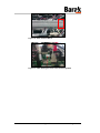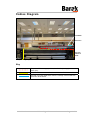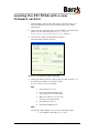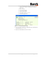
1
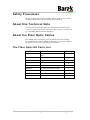
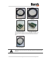
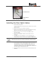
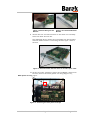
Installing Fiber Optic Cables
Technical Note – 10100117 Rev. C
10100117 - C
© Matan Digital Printers Ltd.
Page 1 of 15
Safety Procedures
Before reading this Technical Note, please refer to the section
on Safety Procedures in the Barak User's Manual.
About this Technical Note
This Technical Note describes the installation of FIBER OPTIC
CABLES on the printer. The procedure must only be carried out
by a qualified Matan Service Engineer.
About the Fiber Optic Cables
The FIBER OPTIC CABLES are more durable than the existing
HIGH SPEED DATA CABLES (HSDC). Therefore, the output will not
be affected by the data pending phenomenon.
The Fiber Optic Kit Parts List
10100117 - C
Part #
Description
10100117
Optical Cable Installation Technical
Note
1
11100665
Optic Converter PCB for BCC sub
2
11100666
Optic Converter PCB for PCI sub
2
88800537
HS Control Cable
2
88800540
BCC Optic Convertor P.S Cable
1
88800539
PCI Optic Converter P.S Cable
1
88800541
Fiber Optic cable
2
10100019
CD for Fiber Kit Upgrade Ver. 14.01
1
66600137
0.5m Ink Tube
2
© Matan Digital Printers Ltd.
Quantity
Page 2 of 15
Figure 1:Fiber Optic Cable
#88800541
Figure 2: HS Control Cable
#88800537
Figure 3: Fiber Optic Converter
Card (PCI) #11100666
Figure 4: Fiber Optic Converter
Card (BCC) #11100665
Please note that the FOCCs that connect to the BCC or the PCI, is the
same card. The only difference is with the metal bracket attached to
them.
Figure 5: PCI Optic Converter
P.S. Cable #88800539
Always make sure that the ends of the Fiber Optic Cables are covered with plastic
protectors.
10100117 - C
© Matan Digital Printers Ltd.
Page 3 of 15
Unprotected cable end
Protected cable end
Figure 6: Fiber Optic Cable Protectors
Installing the Fiber Optic Cables
1. Power down the printer.
If the PC feeds from an external source, make sure it is also
powered down.
2. Remove the top cover, from the CARRIAGE.
3. Remove the transparent covers, from the ELECTRICAL PANEL,
(PDU), located at the rear left side of the printer.
4. Remove the grey covers to reach to the HSDC in the
internal tunnels.
5. Remove the old HSDCs. Make sure that they are not
damaged.
6. Carefully store the old HSDCs, in case something goes
wrong and you need to return to the original configuration.
Please note that the fiber optic cables and PCBs are extremely sensitive.
7. In the FLEXIBLE CABLE CARRIER (IGUS), make sure that the
two channels you used for the HSDCs white cables, are
completely empty—with no other cables inside. You will
need these channels for one of the FIBER OPTIC CABLES and a
low-speed (grey) communication cable.
8. Remove the 2 PCI cards from the PC and disassemble their
brackets.
10100117 - C
© Matan Digital Printers Ltd.
Page 4 of 15
Figure 7: Disassembling the PCI
Bracket
Figure 8: The disassembled PCI
Bracket
9. Attach the two new PCI brackets to the PCIs and carefully
insert the PCIs into the PC.
The following figure shows the assembled new PCI bracket
with the holes used for connecting the fiber optic cable to
the PCI.
Figure 9: New PCI bracket with two holes for the Fiber Optic Cable
10. At the top of the CARRIAGE, where the old HSDC cables were
located, remove the white plastic tie wrap (Figure 10).,
White plastic tie wrap page 5
Figure 10: Removing the white plastic tie wraps
10100117 - C
© Matan Digital Printers Ltd.
Page 5 of 15
11. Attach the two FIBER OPTIC CONVERTER CARDS to the frame of
the CARRIAGE each with a screw, as shown below. The first
figure is a view from the rear of the printer and the second
is from the front (Figure 11, page 6, and Figure 12, page 6).
Fiber Optic Cable (yellow)
Fiber Optic Cable (white)
Retaining Screw
Figure 11: Rear View of the Fiber Optic Converter Card
Fiber Optic
Converter Card
Figure 12: Front View of the Fiber Optic Converter Card
12. Connect the FIBER OPTIC CABLES to the CONVERTER CARDS, in
a 'cross-connect' configuration.
Important Note:
The wires in the fiber cables should be connected in a crossed way, meaning that if
you choose to plug into the BCC the yellow wire to the right side and the white wire to
the left side, so at the PCI side, plug it in crossed, (white/yellow wires Figure 11,
page 6).
10100117 - C
© Matan Digital Printers Ltd.
Page 6 of 15
13. Connect the grey cables to the FIBER OPTIC CONVERTER
CARDS and lead all the cables along the channel of the IGUS
at the same location of the old cables, as shown below.
Grey cables
Fiber optic cables
Figure 13: The grey and fiber optic cables in the IGUS
14. Make sure not to damage the fiber cable connectors, and
make sure they always have the plastic cup protector on
their ends.
10100117 - C
© Matan Digital Printers Ltd.
Page 7 of 15
15. When you reach the area of the curve of the IGUS, wrap
together the INK TUBE and the FIBER OPTIC CABLE—using
tape, as shown below.
Ink Tube
Fiber Optic Cable
Tape
Cable and Ink Tube wrapped
together
16. Carefully slide the wrapped tube and cable underneath the
IGUS chain through the area marked in red, as shown
below.
To avoid damage to the FIBER OPTIC CABLE, only pull the InK
TUBE.
This area is
critical and can
cause damage
to the fiber optic
cables.
Slide the fiber optic
cable underneath
the IGUS chain.
17. Connect the cables, (fiber and grey), to the FIBER OPTIC
CONVERTER CARDS, securing them with the M3 Ellen screws
and springs and washers, to the PCIs, (Figure 14, page 9).
10100117 - C
© Matan Digital Printers Ltd.
Page 8 of 15
Securing screws
Step 18
5VDC feeds the
FOCC from the
main electric panel
J3, use the long
cable, (Figure 7),
with 2 Molex
connectors.
Figure 14: Cable Configuration
18. Connect the long power cable from the PDU connector
Molex number J3 (insert the Molex red pins to +5VDC and
the black pins to -5VDC). Connect the other end of the
cable to the FIBER OPTIC CONVERTER CARDS connected to the
PCIs, (Figure 14 and , page 9Figure 15, page 9).
Figure 15: The J3 Connecter
19. The J3 connector at the main electric panel, supplies 5VDC
to the cards in Figure 14, page 9, (in case the wires are not
black (-)/red, (+), as in Figure 14, page 9, verify with a voltmeter, which is (+) and which is (-)). Then connect the
Molex pins accordingly, as shown in Figure 14, page 9.
20. Connect the short power cable (Figure 5, page 3), from the
5VDC terminal block on the CARRIAGE, to the two FIBER
OPTIC CONVERTER CARDS, (Figure 16 and Figure 17, page 10,
page 10).
10100117 - C
© Matan Digital Printers Ltd.
Page 9 of 15
Figure 16: 5VDC Terminal Block
Figure 17: 5VDC feeding the cards in the left and right BCC
10100117 - C
© Matan Digital Printers Ltd.
Page 10 of 15
Cables Diagram
T.B 5VDC
BCCs area
PC area,
FOCC at
PCIs
PDU, (electric panel), Molex J3
Key
The path of Fiber and grey cables, from BCCs (Carriage) to the
PCIs, (PC).
The path of Power cable 5VDC, from PDU J3 to FOCC at the PCIs
The path of Power cable 5VDC from the carriage Terminal block to
the FOCC at the BCCs.
10100117 - C
© Matan Digital Printers Ltd.
Page 11 of 15
Loading the PCI FPGA with a new
firmware version
1. Perform INIT, check in the HELP ABOUT window that you
have the firmware that were present before the cables
installation.
2. Using the CD, load firmware version 14.1 to the Barak PC,
place it in the following directory: C:\Program
Files\Matan Barak FE\Drivers\PCI and BCC
3. Go to Tools Æ BCC PCI Firmware update.
The following window appears.
Figure 18: The Firmware Update dialog box
4. Using the SELECT button, choose the new file version 14.1
for both PCIs' FPGA, and update them.
If you receive an error message:
PCI
1. Install PCI_UC_10.0.
2. Try to install PCI FPGA14.01
(you will get a fault message).
3. Wait 2-3 minutes, but do not
exit the burning window.
4. Install PCI_UC_01.0.
5. Install PCI FPGA14.01.
BCC
To load the BCC FPGA, carry out the following steps.
1. Load FPGA UP Ver BCC_uc_12.12
10100117 - C
© Matan Digital Printers Ltd.
Page 12 of 15
2. Try to load BCC FPGA with "BCC_fpga_03.01"
version. (You will get an immediate message of
Time Out.)
3. Wait 1 minute.
4. Close Barak FE SW.
5. Open Barak FE SW.
6. Load FPGA UP BCC_uc_01.0.
7. Load BCC_fpga_03.01.
Figure 19: The Help About Barak window
5. The above figure shows the configuration after updating the
PCI FPGA from 12.1 to 14.1.
6. Restart the Barak FE and send a test file.
10100117 - C
© Matan Digital Printers Ltd.
Page 13 of 15
Appendix A: Damage Report Form
(not for Print Head)
Customer’s Name:
Address:
Barak5 Printer S/N*
Faulty Part Name
Details of faulty
part:
Remarks:
Signed:
Name:
Position in
Company:
Date:
* The Printer’s Serial Number is displayed on the label located at the rear of the
printer near the left end of the rollers, as shown below.
10100117 - C
© Matan Digital Printers Ltd.
Page 14 of 15
Document History
Rev
ECO #
Written by
Date
Approved by
Date
Remarks
A
B
10000049
F. Taylor
F. Taylor
F. Taylor
15-02-11
29-03-11
12-04-11
Ronen Shalil
Ronen Shalil
15-02-11
29-03-11
New document
New Parts List
Workaround
PCI/FPGA
Head Office
Matan Digital Printers Ltd., 14 Amal Street, Park Afek, Rosh Ha'ayin 48092, Israel.
Tel: (+972) 3 9002720 Fax: (972) 3 9002721 Email: [email protected]
U.S. Office
Matan USA Inc., 90, Earhart Drive, Suite 4, Williamsville NY 14221.
Tel: (+1) 716 631 3770 Fax: (1) 716 631 3576
Email for customer support: [email protected]
Europe Office
Matan EU, C/ Rosalia de Castro, 21, 08025, Barcelona, Spain.
Tel: (+34) 902 932825 Fax: (+34) 902 932826
Email for customer support: [email protected]
10100117 - C
© Matan Digital Printers Ltd.
Page 15 of 15