1
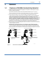
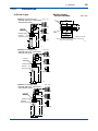
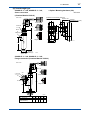
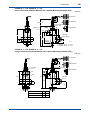
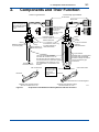
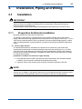
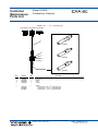
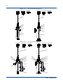
User’s Manual CONDUCTIVITY METERING SYSTEM Model SC8SG CONDUCTIVITY DETECTOR IM 12D08G02-01E R IM 12D08G02-01E 5th Edition i < Introduction > Introduction Conductivity Measuring System consists of a SC8SG Conductivity Detector, as described in this manual, used in conjunction with a SC202, FLXA202/FLXA21 or SC402G, SC450G Conductivity Converter. The SC8SG Conductivity Detector may use sensors with cell constant of 0.01 cm-1, to measure conductivities of 0 to 100 µS/cm, or sensors with cell constant of 10 cm-1, to measure conductivities of 0 to 1000 mS/cm. The sensors with cell constants of 10 cm-1 may be two-electrode or four-electrode types: fourelectrode types have the advantage that they are much less likely to be affected by polarizationrelated errors, so can be more consistent and accurate both with liquids that are likely to adhere to and stain the electrodes, and with liquids having high conductivities. The SC8SG detector may be inserted into the process piping, for direct measurement of process liquids, or a sample of the liquid may be obtained via a piping connection. This user manual is intended to cover installation, piping and wiring, periodic inspection and maintenance for the SC8SG Conductivity Detector. This manual does not describe the units in Table shown below which are the component units of the conductivity measuring system. Each of these units comes with an instruction manual, so read the applicable manuals for details of the units concerned. Model User’s manual Manual number FLXA202, FLXA21 2-Wire Liquid Analyzer IM 12A01A02-01E SC402G Conductivity and Resistivity Converter IM 12D08N04-01E SC450G Conductivity and Resistivity Converter IM 12D08N05-01E SC202G SC202SJ 2-Wire Conductivity Transmitter IM 12D08B02-01E Upon delivery, unpack the instrument carefully and inspect it to ensure that it was not damaged during shipment. If damage is found, retain the original packing materials (including the outer box) and then immediately notify the carrier and the relevant YOKOGAWA sales office. Make sure the model code on the label agrees with your order. For the meaning of the model code, refer to the Model and Suffix code table (see subsection 1.2.2). Media No. IM 12D08G02-01E 5th Edition : Oct. 2015 (YK) All Rights Reserved Copyright © 2004, Yokogawa Electric Corporation IM 12D08G02-01E 5th Edition : Oct.28,2015-00 ii < Introduction > For the safe use of this equipment n Safety, Protection, and Modification of the Product • In order to protect the system controlled by the product and the product itself and ensure safe operation, observe the safety precautions described in this user’s manual. We assume no liability for safety if users fail to observe these instructions when operating the product. • If this instrument is used in a manner not specified in this user’s manual, the protection provided by this instrument may be impaired. • Be sure to use the spare parts approved by Yokogawa Electric Corporation (hereafter simply referred to as YOKOGAWA) when replacing parts or consumables. • Modification of the product is strictly prohibited. • The following symbols are used in the product and user’s manual to indicate that there are precautions for safety: n Notes on Handling User’s Manuals • Please hand over the user’s manuals to your end users so that they can keep the user’s manuals on hand for convenient reference. • Please read the information thoroughly before using the product. • The purpose of these user’s manuals is not to warrant that the product is well suited to any particular purpose but rather to describe the functional details of the product. • No part of the user’s manuals may be transferred or reproduced without prior written consent from YOKOGAWA. • YOKOGAWA reserves the right to make improvements in the user’s manuals and product at any time, without notice or obligation. • If you have any questions, or you find mistakes or omissions in the user’s manuals, please contact our sales representative or your local distributor. n Warning and Disclaimer The product is provided on an “as is” basis. YOKOGAWA shall have neither liability nor responsibility to any person or entity with respect to any direct or indirect loss or damage arising from using the product or any defect of the product that YOKOGAWA can not predict in advance. IM 12D08G02-01E 5th Edition : Oct.28,2015-00 iii < Introduction > n Symbol Marks Throughout this user’s manual, you will find several different types of symbols are used to identify different sections of text. This section describes these icons. WARNING Indicates a potentially hazardous situation which, if not avoided, could result in death or serious injury. CAUTION Indicates a potentially hazardous situation which, if not avoided, may result in minor or moderate injury. It may also be used to alert against unsafe practices. IMPORTANT Indicates that operating the hardware or software in this manner may damage it or lead to system failure. NOTE Draws attention to information essential for understanding the operation and features. IM 12D08G02-01E 5th Edition : Oct.28,2015-00 iv < Introduction > After-sales Warranty n Do not modify the product. n During the warranty period, for repair under warranty consult the local sales representative or service office. Yokogawa will replace or repair any damaged parts. Before consulting for repair under warranty, provide us with the model name and serial number and a description of the problem. Any diagrams or data explaining the problem would also be appreciated. l If we replace the product with a new one, we won’t provide you with a repair report. l Yokogawa warrants the product for the period stated in the pre-purchase quotation Yokogawa shall conduct defined warranty service based on its standard. When the customer site is located outside of the service area, a fee for dispatching the maintenance engineer will be charged to the customer. n In the following cases, customer will be charged repair fee regardless of warranty period. • Failure of components which are out of scope of warranty stated in instruction manual. • Failure caused by usage of software, hardware or auxiliary equipment, which Yokogawa Electric did not supply. • Failure due to improper or insufficient maintenance by user. • Failure due to modification, misuse or outside-of-specifications operation which Yokogawa does not authorize. • Failure due to power supply (voltage, frequency) being outside specifications or abnormal. • Failure caused by any usage out of scope of recommended usage. • Any damage from fire, earthquake, storms and floods, lightning, disturbances, riots, warfare, radiation and other natural changes. n Yokogawa does not warrant conformance with the specific application at the user site. Yokogawa will not bear direct/indirect responsibility for damage due to a specific application. n Yokogawa Electric will not bear responsibility when the user configures the product into systems or resells the product. n Maintenance service and supplying repair parts will be covered for five years after the production ends. For repair for this product, please contact the nearest sales office described in this instruction manual. IM 12D08G02-01E 5th Edition : Oct.28,2015-00 v < CONTENTS > CONDUCTIVITY METERING SYSTEM Model SC8SG CONDUCTIVITY DETECTOR IM 12D08G02-01E 5th Edition CONTENTS Introduction.....................................................................................................i For the safe use of this equipment..............................................................ii After-sales Warranty....................................................................................iv 1.General....................................................................................................... 1-1 1.1 Features of SC8SG Conductivity Detector..................................................... 1-1 1.2 Specifications..................................................................................................... 1-2 1.2.1 Standard Specifications...................................................................... 1-2 1.2.2 Model and Suffix Codes...................................................................... 1-4 1.2.3Dimensions......................................................................................... 1-6 2. Components and Their Function............................................................. 2-1 3. Installation, Piping and Wiring................................................................. 3-1 3.1Installation.......................................................................................................... 3-1 3.1.1 Preparation for Detector Installation................................................... 3-1 3.1.2 Detector Installation............................................................................ 3-4 3.2Piping.................................................................................................................. 3-5 3.2.1 Piping Materials.................................................................................. 3-5 3.2.2 Making Sampling piping...................................................................... 3-5 3.3Wiring.................................................................................................................. 3-8 3.3.1 Detector Cable Specifications............................................................ 3-8 3.3.2 Laying Detector Cables...................................................................... 3-8 4.Operation.................................................................................................... 4-1 4.1 4.2 Preparation for Operation................................................................................. 4-1 4.1.1 Checking Piping and Wiring................................................................ 4-1 4.1.2 Flowing Measured solution................................................................. 4-1 4.1.3 Checking Operation............................................................................ 4-1 Steady-State Operation..................................................................................... 4-2 4.2.1 If any problem arises during operation............................................... 4-2 4.2.2 Cautions When Stopping or Resuming Operation............................. 4-2 IM 12D08G02-01E 5th Edition : Oct.28,2015-00 5. vi < CONTENTS > Inspection and Maintenance.................................................................... 5-1 5.1 Cleaning the Detector........................................................................................ 5-1 5.1.1 Guidelines for Cleaning...................................................................... 5-1 5.1.2 Removing the Detector....................................................................... 5-1 5.1.3Cleaning.............................................................................................. 5-2 5.2 Inspection of O-ring Sealing ............................................................................ 5-2 Customer Maintenance Parts List.......................................CMPL 12D08G02-01E Revision Information................................................................................................i IM 12D08G02-01E 5th Edition : Oct.28,2015-00 1-1 < 1. General > 1.General 1.1 Features of SC8SG Conductivity Detector ● SC8SG can measure conductivities ranging from 0.05 µS/cm to 1000 mS/cm so can be used in a variety of processes. The SC8SG Conductivity Detector has a cell constant of either 0.01 cm-1 or 10 cm-1. These two detectors can measure conductivities ranging from 0 µS/cm to 1000 mS/cm. ● High conductivity solutions can be measured stably for prolonged periods of time. In high-conductivity solution measurements, polarization is likely to cause measurement errors. Two-electrode and four-electrode detectors with cell constants of 10 cm-1 are available for measurement of high-conductivity solutions. Four-electrode detectors are less likely to be affected by polarization, enabling more stable measurements, and they can measure conductivity of solutions with high conductivities. Polarization may also be caused by contamination of electrodes. The four-electrode detector is less likely to be affected by polarization, and is less affected by dirty electrodes, so requires less maintenance. ● Direct mounting on the process piping also allows the detector to measure the conductivity of high-temperature solutions. We offer both Flow-through (sampling) type and Screw-in type SC8SG Conductivity Detectors with a cell constant of 0.01 cm-1 can measure solutions with temperatures up to 130°C; this allows measurement of hot boiler water and the like. Pt 1000 sensor in the detector provides precise temperature measurement for reference temperature conversion. Screw-in type detector Flow-through type detector Pin terminals Pin terminals Fork terrninals Fork terminals Ring terrninals Ring terrninals The figure shows a detector with a four-electrode sensor of cell constant 10 cm-1. The figure shows a detector with a polypropylene chamber flange connection. F01-1.ai Figure 1.1 External Views of SC8SG Conductivity Detectors IM 12D08G02-01E 5th Edition : Oct.28,2015-00 1.2 1-2 < 1. General > Specifications 1.2.1 Standard Specifications Cable with pin terminals (applicable to FLXA202/FLXA21, SC202G and SC202SJ) Cable with M3 ring terminals (applicable to SC450G) Cable with M4 ring terminals (applicable to FLXA202/FLXA21) Object of measurement: Conductivity of solutions Measuring principle: 2-electrode system or 4-electrode system Cell Constants:0.01 cm-1 or 10 cm-1 (for two-electrode system), 10 cm-1 (for four-electrode system) Measuring Ranges: 0-0.5 μS/cm to 0-100 μS/cm for a cell constant of 0.01 cm-1 0-1 mS/cm to 0-1000 mS/cm for a cell constant of 10 cm-1 Temperature Range: 0˚ to 100˚C (130˚C maximum only for 0.01 cm-1 cell constant detectors, excluding those with polypropylene chambers) Pressure: 1000 kPa max. (500 kPa maximum for detectors with polypropylene chambers) Flow rate of Sample Solution: No particular limitation applies, although a value of less than 20 L/min is recommended for Flow-through detectors. Note: No limitation applies to flow rate (flow velocity) as far as measurement is concerned. Take care, however, when using Flowthrough detectors. Electrodes or the inner walls of a liquid chamber may wear put drastically at higher flow speeds if a measured solution contains slurry. Air bubbles should not be mixed in the sample solutions to obtain correct measured values. RTD for Temperature Compensation: Pt1000 (built into the sensor) Construction: Screw-in type or Flow-through types. Rainproof encapsulation (compatible with the JIS C0920 Japanese Industrial Standard) Installation: • Screw-in type; held by the process piping • Flow-through type (polypropylene chamber); mounted on a pipe (nominal diameter of 50 mm ±2 in) • Flow-through type (SCS14 chamber); held by the process piping Process Connection: Screw-in or Flow-through Construction of Wetted Part: • Sensor-holding base; Stainless steel (316 SS) and Fluoro rubber when using Screw-in type holder or the chamber made of stainless steel. PP and Fluoro rubber when using the chamber made of PP. • 0.01 cm-1 cell constant, two-electrode sensor; Stainless steel (316 SS) and ethylene chloride trifluoride • 10 cm-1 cell constant, two-electrode sensor; reinforced epoxy resin and graphite • 10 cm-1 cell constant, four-electrode sensor;polyvinylidene difluoride, glass and platinum • Chamber (Flow-through type); SCS14 or polypropylene resin IM 12D08G02-01E 5th Edition : Oct.28,2015-00 < 1. General > 1-3 Weight: Screw-in type; approximately 1.3 kg (excluding the cable) Flow-through type (SCS14 chamber); approximately 3.1 kg (excluding the cable) Flow-through type (SCS14 chamber, flanged); approximately 4.5 kg (excluding the cable) Flow-through type (polypropylene chamber); approximately 2.7 kg (excluding the cable) Flow-through type (polypropylene chamber, flanged); approximately 3.2 kg (excluding the cable) Cable ; 0.3 kg for 5.5-m length ; 0.5 kg for 10-m length ; 0.9 kg for 20-m length. IM 12D08G02-01E 5th Edition : Oct.28,2015-00 1-4 < 1. General > 1.2.2 Model and Suffix Codes (1)SC8SG Option Description Code ............................................. ............... Conductivity detector SC8SG .............. Low range; cell constant: 0.01 cm-1 Measuring -R31 .............. High range; cell constant: 10 cm-1 range -R61 .............. 2-electrode system (for both 0.01 cm-1 and 10cm-1 cell constants) Electrode -T configuration - for general measurements (*1) .............. 4-electrode system (for 10 cm-1 cell constant only) -F - for countermeasures against polarization due to contamination (*2) .............. with welding socket (*3) Screw-in type -100 .............. without welding soket -101 (a welding socket [K9208BK] should be ordered separately) .............. Rc1/2 female threaded; chamber material: SCS14 -302 Flow-through type .............. Rc1/2 female threaded; chamber material: PP -312 (*7) .............. 1/2NPT female threaded; chamber material: SCS14 -303 .............. 1/2NPT female threaded; chamber material: PP -313 .............. JIS 10K 15 RF flange; chamber material: SCS14 -304 .............. JIS 10K 15 FF flange; chamber material: PP -314 .............. ANSI Class150 1/2 RF flange with serration; chamber material: SCS14 -305 .............. ANSI Class150 1/2 FF flange; chamber material: PP -315 .............. Cable length -P1 5.5 m (special cable supplied with detector) (pin terminals) .............. 10 m (special cable supplied with detector) (pin terminals) -P2 .............. 20 m (special cable supplied with detector) (pin terminals) (*4) -P3 .............. 5.5 m (special cable supplied with detector) (fork terminal) -F1 .............. 10 m (special cable supplied with detector) (fork terminal) -F2 .............. 20 m (special cable supplied with detector) (fork terminal) (*4) -F3 .............. 5.5 m (special cable supplied with detector) (M4 ring terminal) (*5) -X1 .............. 10 m (special cable supplied with detector) (M4 ring terminal) (*5) -X2 .............. 20 m (special cable supplied with detector) (M4 ring terminal) (*5) -X3 .............. 5.5 m (special cable supplied with detector) (M3 ring terminal) (*6) -Y1 .............. 10 m (special cable supplied with detector) (M3 ring terminal) (*6) -Y2 .............. 20 m (special cable supplied with detector) (M3 ring terminal) (*6) -Y3 .............. Style A Style code *A Suffix Code Construction Model /PS /SS Option *1: *2: *3: *4: *5: *6: *7: Stainless Steel Mounting hardware (for PP chamber) Stainless Steel Mounting hardware (for SCS14 chamber) The cell constant is 0.01 cm-1 when the combiration of measuring range -R31 and Electrode configuration -T is chosen. The cell constant is 10 cm-1 when the combination of measuring range -R61 and Electrode configuration -T is chosen. Electrode configuration -F cannot be chosen when -R31 is chosen. For process where can give contamination to a detector, a four-electrode detector, the combination of -R61 and -F, should be used. If a welding socket (K9208BK) needs to be ordered beforehand, either place a separate order or prepare one by referring to the extemal view later in this brochure. Impossible use for the SC400G. Used for connection to FLXA202/FLXA21. Used for connection to SC450G, SC202/TB. The model is not equipped with a mounting hardware, please place an order on the SC8SG with option code /PS or /SS when you select flow-through model. The PP chamber can have cracks or splits unless it is not supported by a mounting hardware. Applicable transmitter/converters for SC8SG Converter Type of terminals Pin Converter: SC100 Ring M4 Ring M3 N.A. Transmitter: SC202G, SC202SJ Yes N.A. Yes (*1) Converter:SC402G (*3) Yes N.A. N.A. Converter: SC450G (*2) N.A. Yes Analyzer: FLXA202/FLXA21 Yes Yes N.A. *1: *2: *3: Applicable when option code /TB (screw terminal) specified for SC202G/SC202SJ. Both pin and M3 ring can be used for SC450G, but M3 ring are recommended. SC402G has been terminated. IM 12D08G02-01E 5th Edition : Oct.28,2015-00 < 1. General > 1-5 (2)Spare Parts for SC8SG Parts No. K9208BA K9208BC K9208BD K9208BK G9303EB Description 0.01 cm-1 cell constant, two-electrode sensor 10 cm-1 cell constant, two-electrode sensor 10 cm-1 cell constant, four-electrode sensor Welding socket for Screw-in model O-ring (3)WU41 Model Suffix code Option code ..................... .......................... Dedicated Cable for SC8SG ......................... fork terminals Cable end -F ......................... pin terminals -P ......................... M4 ring terminals (*1) -X ......................... M3 ring terminals (*2) -Y ......................... 5.5 m Cable length -05 ......................... 10 m -10 ......................... 20 m -20 Description WU41 *1: *2: Used for connection to FLXA202/FLXA21. Used for connection to SC450G, SC202/TB IM 12D08G02-01E 5th Edition : Oct.28,2015-00 1-6 < 1. General > 1.2.3Dimensions (1)Screw-in type Unit : mm SC8SG-R31-T-100 (Low range) Electrode with 0.01cm-1 Cell constant Two-electrode system Welding socket Parts No: K9208BK C1 ø55 3 Pin terminals Locknuts (M48 x 2) C1 Fork terminals Outlet for measured solution ø42 Ring terminals 156 (5) ø45 ø50 ± 0.2 192 22 27 3 Approx.78 Welding socket Unit : mm Material: 316 SS Note: If you make the welding socket for Screw-in type, refer to the above drawing. F16.ai 95 F13.ai ø30 Unit : mm SC8SG-R61-T-100 (High range) Electrode with 10 cm-1 Cell constant Two-electrode system Pin terminals Locknuts (M48 x 2) Approx.78 Fork terminals Welding socket Outlet for measured solution 221 Ring terminals 185 125 ø30 F14.ai SC8SG-R61-F-100 (High range) Electrode with 10 cm-1 Cell constant Four-electrode system Unit : mm Pin terminals Locknuts (M48 x 2) Approx.78 Fork terminals Welding socket Outlet for measured solution 221 185 Ring terminals 125 ø30 F15.ai IM 12D08G02-01E 5th Edition : Oct.28,2015-00 1-7 < 1. General > (2)Flow-through type SC8SG-R□1-□-302, SC8SG-R□1-□-303, ● Option: Mounting hardware (-SS) Screw connection Unit: mm (Chamber Material: SCS14) Unit : mm (Chamber of Conductivity detector) approx. 102 50A pipe (provided by the user) Pin terminals Locknuts 20 Approx. 78 55 Rc1/2 or 1/2NPT(F) Fork terminals 203 42 260 Ring terminals 70 100 172 Approx. Ø58 Rc1/2 or 1/2NPT(F) F21.ai F19.ai SC8SG-R□1-□-304, SC8SG-R□1-□-305, Flange connection (Chamber Material: SCS14) Unit : mm Pin terminals Approx. 78 4 - øh holes øG Fork terminals øC øD t 205 75 293 Ring terminals F20.ai Flange rating øC øD øG øh t JIS 10K 15 RF 70 95 52 15 12 ANSI Class150 1/2 RF 60.5 88.9 34.9 15.7 11.2 (with serration) IM 12D08G02-01E 5th Edition : Oct.28,2015-00 1-8 < 1. General > SC8SG-R□1-□-312, SC8SG-R□1-□-313, Screw connection (Chamber Material: PP) + Option (Mounting hardware (/PS) ) Unit: mm Pin terminals Fork terminals Approx. 78 Mounting hardware Option : /PS Rc 1/2 (*1) Ring terminals 1/2NPT (*2) 203 87 305 40 99 50A pipe (O.D. ø60.5) 170 217 Rc 1/2 47 100 53 1/2NPT F17.ai *1: SC8SG - R 1 - - 312 *2: SC8SG - R 1 - - 313 SC8SG-R□1-□-314, SC8SG-R□1-□-315, Flange connection (Chamber Material: PP) + Option (Mounting hardware (/PS) ) Unit: mm Pin terminals Fork terminals Approx. 78 4 - ø15 holes 12 Mounting hardware Option : /PS Ring terminals øC øD 203 85 303 99 50A pipe 215 47 98 100 F18.ai Flange rating JIS 10K 15 FF ANSI Class150 1/2 FF øC øD 70 60.5 95 88.9 IM 12D08G02-01E 5th Edition : Oct.28,2015-00 1-9 < 1. General > (3)WU41 Dedicated cable Unit: mm PG9 64.5 Approx. 100 Pin terminal White Brown Green Yellow Black Red ø29 Cable lengh: 5.5 m, 10 m, 20 m 16 11 15 Fork terminal Ring terminal 14 13 12 Earth F22.ai IM 12D08G02-01E 5th Edition : Oct.28,2015-00 Blank Page 5th Edition : Oct.28,2015-00 2. 2-1 < 2. Componens and Their Function > Components and Their Function Screw-in Type Detector Flow-through Type Detector Pin terminals Name plate The Screw-in type shown in the figure has a two-electrode detector with cell constant of 10 cm-1. Detector cables connected to detectors with specified connectors. 5.5/10/20-m cable selectable. Connector locknuts Detector cables are locked to detectors. Socket Welded to detector inlet on process piping. Washer O-ring Flow direction of measured solution Flow direction of measured solution Washer O-ring Locknuts to fix detectors, and O-ring to prevent leakage of measured solution. Detector Two types of detector available: One with cell constant of 0.01 cm-1 and the other with cell constant of 10 cm-1. Two-electrode and four-electrode systems are available for cell constant of 10 cm-1. A Pt 1000Ω RTD is incorporated in the detector. Cell constant label Electrode Socket screw into chamber. Outlet for measured solution Liquid chamber Stainless steel or polypropylene chambers may be specified. Screwed or flange connections may be specified for pipe connections. The Flow-through Inlet for measured solution type detector shown in the figure uses a stainless steel screw-connection Electrode chamber. Cell constant label Note: Electrodes are connected together. ● Detector (two-electrode system) with cell constant of 0.01 cm-1 Figure 2.1 ● Detector (two-electrode system) with cell constant of 10 cm-1 F0201.ai Components of the SC8SG Conductivity Detector and Their Functions IM 12D08G02-01E 5th Edition : Oct.28,2015-00 Blank Page 3. 3-1 < 3. Installation, Piping and Wiring > Installation, Piping and Wiring 3.1Installation IMPORTANT When ultra-pure water flows through plastic pipe, electrostatic charge may be produced. When the sensor is installed on this plastic pipe, the electrostatic charge goes through the sensor, and into a converter circuit This electrostatic charge will discharge and damage electronic parts on the converter circuit. 3.1.1 Preparation for Detector Installation Mounting the detector varies with its construction. The Screw-in type detector is mounted directly to the detector insertion port on the process piping, while the flow-through type detector is mounted on a 2-inch pipe (O.D 60.5-mm) – or on a wall, and the measured solution flow to the detector via user-provided sampling piping. In either case, provide appropriate mounting hardware for detector. Mounting procedures are described below. (1) Screw-in type detector The detector electrodes are mounted on the probe inner circumference, and conductivity measurement is performed for solutions flowing through the inside (see Figure 2.1). So, when using the Screw-in type detector, you need to give due consideration to solution flow inside the probe, and give special consideration to installation location when prompt response to changes in conductivity is required. [Installation conditions for the Screw-in type detector] ● The measured solution outlet in the detector probe is immersed in the measured solution. In addition, there should be no bubbles at the measurement point. ● In general, the tip of the detector probe should be oriented to upstream of the flow. NOTE A two-electrode detector with cell constant of 10 cm-1 can also be installed perpendicular to the solution flow. In addition, if the speed of response is not so important because conductivity value and temperature change gradually, there is no restriction on detector mounting position. IM 12D08G02-01E 5th Edition : Oct.28,2015-00 3-2 < 3. Installation, Piping and Wiring > Flow of measured solution B A F0301.ai -1 A two-electrode detector with a cell constant of 0.01 cm should be installed in positions A above. A two-electrode detector with a cell constant of 10 cm-1 should be installed in positions A or B above. A four-electrode detector with a cell constant of 10 cm-1 should be installed in positions A above. Figure 3.1 Orientation of the Detector relative to Flow of Measured Solution ● At the measurement point, the temperature and pressure of the measured solution should not exceed the limits specified (refer to Section 1.2.1, earlier in this manual) ● Detectors should be removed for maintenance (when the detector is removed, make sure that the measured solution does not flow out of the insertion port). [Machining the detector insertion port] Figure 3.2 shows the dimensions of the detector insertion port. Unit: mm ø36 +0.2 0 ø31 O-ring Seal Area 4 14 17 M48x2 Locknut ø49 Fixing Nut Washer 80 mm max. ø31 Solution Levle 212 mm min. O-ring Measured Solution Detector Probe Detector mounted on its insertion port F0302.ai Figure 3.2 Structure of Screw-in Type Detector Mounting Section IM 12D08G02-01E 5th Edition : Oct.28,2015-00 3-3 < 3. Installation, Piping and Wiring > To facilitate machining the detector insertion port, the company has prepared sockets as shown in Figure 3.3. The detector mounting section of these sockets are machined as shown in Figure 3.2. ø55 Unit: mm 27 (22) 3 3 5 Welded all around the circumference [45 Detector O-ring Direction of Measured Solution Flow K9208BK Welded Socket C1 ø50±0.2 50X50X40 (Sch 40), reducing T (Hole Drilled: ø50.5 mm) K9208BK Welded Socket (flush mounting) Material: 316 SS ø54 Ball Valve 50X40 Reducer When screwed sockets are used, drill an Rc1-1/2 (or 1-1/2 NPT) thread. Elbow Hexagonal Part 22 Ball Valve 48 a T Pipe Thread Figure 3.3 Position of Standard Diameter Example of an insertion port provided in a small pipe F0303.ai K9208BH threaded socket (T: R 1-1/2, a: approx. 13) Material: 14 SS K9208BJ threaded socket (T: 1-1/2 NPT, a: approx. 11) Material: 14 SS Dimensions of Insertion Holes and Sockets (2) Flow-through detector Mounting of flow-through type detectors depends on chamber material. In general, this type of detector is mounted vertically so that the measured solution inlet is (horizontal or) oriented downwards. Note: The flow-through detector may also be mounted either on a slant or horizontally, but the measured solution outlet should be oriented to point upwards. [Installation conditions for the flow-through detector] ● The installation location should be chosen so that the sampling pipe is short. Note: If the sampling pipe is long, rapid fluctuations in the conductivity of the process solution may not be detected in the measured value. [Detector installation requirements] a. When a stainless steel (SCS14) chamber is used: Basically, the detector should be supported by the connecting pipes. Install the detector when the sampling pipes are installed (refer to Section 3.2). b. When a polypropylene chamber is used: Install the detector on a pipe of nominal size 50-mm (outer diameter 60.5 mm) or on a plate. When the detector is mounted on a pipe, fasten the detector to the mounting pipe with a U-shaped bolt. Install the pipe either vertically or horizontally. When the detector is mounted on a plate, remove the pipe mounting bracket from the detector and fix the detector to the mounting plate with two M8 screws. Drill two 9-mm dia. holes in the mounting plate as shown in Figure 3.4. IM 12D08G02-01E 5th Edition : Oct.28,2015-00 3-4 < 3. Installation, Piping and Wiring > 50 Unit: mm Two 9 mm Dia. Holes Bracket Mounting Screw (four) Mounting Bracket (3.2 mm thick) M8 Screws (two), 14 mm long Washers (two) 60 Two M8 Screw Holes (Note) M8 screw are positioned 35 mm below the top of the mounting bracket. Location of Measured Solution Outlet The measured solution outlet can be positioned on the left (as shown in Figure 3.4), on the right, forwards or backwards. To change the position, loosen the bracket mounting screw. If the measured solution outlet is positioned backwards, place the bracket upside down. (For flange connected detectors, note the position and shape of the mounting plate.) F0304.ai Figure 3.4 3.1.2 Hole Drilling for Plate Mounting Detector Installation A Screw-in type detector is attached to the socket provided on the detector insertion port (see Figure 3.2). Be sure that the O-ring is installed in the socket, and tighten the fixing nut firmly. mark sure that the measured solution outlet points to the downstream side of the measured solution flow as indicated by the arrow mark. A flow-through type detector with polypropylene chamber material should be mounted securely on its mounting pipe in the predetermined position. A flow-through type detector with a 14 SS stainless steel chamber should be installed at the same time as sampling pipes are installed. IM 12D08G02-01E 5th Edition : Oct.28,2015-00 3-5 < 3. Installation, Piping and Wiring > 3.2Piping When using a flow-through type detector, make a sampling piping connection to flow the process solution into the detector. This section describes the procedures for sampling pipe connection. When connecting flow-through detectors directly on the process piping, follow the instruction in the section. 3.2.1 Piping Materials When flow-through detectors are screw-connected, an Rc 1/2 or 1/2 NPT thread female connection is provided. For flange-connected detectors, when the chamber material is polypropylene the provided flange may be JIS 10K 15 FF equivalent or ANSI Class150 1/2 FF, and when the chamber material is SCS14 the provided flange may be JIS 10K 15 RF or ANSI Class150 1/2 RF with serrations. Use the following piping materials for piping connected to the detector. Select piping joints appropriate for the piping materials used. [For polypropylene chambers] ● Hard polyvinyl chloride pipe (JIS K 6741), nominal diameter 16 mm ● polypropylene pipe, nominal diameter 16 mm ● Wire mesh reinforced flexible PVC tube, nominal diameter 15 mm [For stainless steel chamber] ● Stainless steel pipe (JIS G 3459) ● Stainless steel (304 SS) or Stainless steel (316 SS), nominal diameter 15 mm 3.2.2 Making Sampling piping Make sampling piping as per the following procedures: (1) Cautions when making piping [Pressure of the measured solution] When a stainless steel (SCS14) chamber is used, pressure of the measured solution can be up to 1 MPa. When a polypropylene (PP) chamber is used, pressure of the measured solution can be up to 500 kPa maximum. Absolute maximum pressure of the measured solution also depends on the piping materials used. [Flow of the measured solution] There are no special restriction on flow (flow velocity) as regards measuring conductivity. NOTE If the temperature of the measured solution varies, and the conductivity is converted to a value at a reference temperature, the response of the temperature detector must be taken into account. Note that under normal measuring conditions, the temperature detector in the SC8SG conductivity detector has sufficiently fast response the flow velocity of the measured solution will not be an issue. However, if measured solutions containing slurry are passed through the detector and chamber at high rates of flow, the detector or chamber may be worn out by abrasion. To avoid this, you should restrict maximum flow rate to about 20 liters/min. and aim for a minimum flow rate of about 1 liter/min. IM 12D08G02-01E 5th Edition : Oct.28,2015-00 3-6 < 3. Installation, Piping and Wiring > [Temperature of the measured solution] The maximum temperature of the measured solution is restricted according to the heat resistance of the chamber and piping materials used. NOTE The maximum temperature for a polypropylene (PP) chamber is 80°C. For a stainless steel (SCS14) chamber, the maximum temperature of the measured solution is 100°C for detector with a cell constant of 0.01 cm-1, or 130°C for detectors with a cell constant of 10 cm-1. When reference temperature conversion is performed, choosing a reference temperature that is close to the measurement temperature reduces the effect of the accuracy of the temperature coefficient on measurement accuracy. [Bubbles in measured solution] If the measured solution contains bubbles, this may cause the measured value to fluctuate. If the measured solution contains large amounts of bubbles, or where bubbles are generated by a pressure drop, use an overflow tank as shown in Figure 3.5 to reduce the bubbles. Overflow Tank Stop valve Drain pipe Process piping F0305.ai Figure 3.5 Piping Example where Measured Solution contains large amounts of bubbles (2) Procedures for piping [Position of the measured solution outlet] When a polypropylene chamber is used, be sure that the outlet for the measured solution is correctly oriented the piping. The measured solution outlet can be oriented either forward, to the right or left. When the detector is plate-mounted, the measure solution outlet can also be oriented backwards (see figure 3.4 for reference). To change the direction of the measured solution outlet, remove the detector together with the socket, and loosen the four bracket mounting screws as shown in Figure 3.6 to remove the solution chamber. Note: The measured solution outlet is oriented to the right side at the factory before shipment. IM 12D08G02-01E 5th Edition : Oct.28,2015-00 3-7 < 3. Installation, Piping and Wiring > Bracket Mounting Screws (four) Bracket Chamber Pipe Mounting Bracket F0306.ai Figure 3.6 Removing Bracket Where the detector is mounted horizontally, be sure that the measured solution outlet is oriented upwards. Piping to Measured Solution Outlet Be sure to orient upwards. Mark the pipe as short as possible, and install a stop valve. Piping to Measured Solution Inlet Detector Solution Chamber Note: If the detector is removed from a horizontally-installed detector, solution inside the chamber will flow out. Socket Installation Location Figure 3.7 F0307.ai Piping Connection Where Detector Solution Chamber Is Positioned Horizontally [To help avoid problems with the detector] Use appropriate materials for piping, to avoid corrosion or damage. ● If corrosive components are contained in the measured solution, take special care in selecting sealing parts – such as gaskets, and the like – with corrosion resistance. ● If the detector is mounted on – and supported by – the piping, it is likely that force may be applied to the piping during detector maintenance. To avoid this, provide a support adjacent to the detector, and fix the piping to the support. ● If slurries are likely to accumulate in the solution chamber, provide an appropriate drain connection in the measured solution inlet. [For safety, during maintenance] ● Provide a stop valve to prevent the measured solution from running out of the detector insertion section when the detector is removed for inspection or maintenance. IM 12D08G02-01E 5th Edition : Oct.28,2015-00 3-8 < 3. Installation, Piping and Wiring > 3.3Wiring 5.5-m, 10-m or 20-m long detector cables are supplied with the conductivity detector according to the customer's specifications. Connect the detector cables to the converter terminals (see Figure 3.8). 3.3.1 Detector Cable Specifications Cable length: 5.5 meters (suffix code: -¨1) 10 meters (suffix code: -¨2) 20 meters (suffix code: -¨3) Cable outside diameter: Approximately 9.5 mm Maximum cable temperature: 50°C Terminal treatment: Detector: Use a rain-proof connector with locknut. Converter: Pin-shaped , fork-shaped or ring-shaped terminals. 3.3.2 Laying Detector Cables [Notes for laying detector cables] ● The conductivity detector requires calibration. The detector should be easy to remove for calibration and maintenance. ● Cabling should not touch any pipes or the like that may get hotter than 50°C. [Procedures for laying detector cables] First check that the inside of the connector is not wet. Then connect cables to the detector. After connecting, tighten the connector locknut completely, to maintain rainproofness. Note: The resistance value between cable cores 11 (12) and 13 (14), 11 (12) and 15 (16) and 13 (14) and 15 (16) usually should be at least 2 MΩ. Connect other end of the detector cable to the converter terminals. Check the marking on cable cores and connect each core to the corresponding converter terminal. Note: For more details on converter wiring, including the converter cable entry port, refer to the separate converter user's manual. Conductivity Converter 11 Cable 12 13 14 Connector Pt1000 15 Electrodes 16 F0308.ai Conductivity Detector Figure 3.8 Connecting Detector Cable IM 12D08G02-01E 5th Edition : Oct.28,2015-00 4-1 < 4. Operation > 4.Operation Check that the conductivity measuring system is operating correctly and providing appropriate measurements. Then place the system in steady operation. For converter operating instruction, refer to the separate converter User's Manual. This chapter provides operating instructions for detectors. 4.1 Preparation for Operation 4.1.1 Checking Piping and Wiring [Checking Wiring] Check that detector cable connections are correct. ● Check that calibration can be performed without any problems. ● Check that the sensor cable connector is secured with the associated locknut. ● Check that the detector cable is appropriately protected from damage. ● Check that the detector cable length is appropriate. [Piping and detector installation conditions] ● Confirm that (temperature and corrosion resistance of) piping materials is appropriate for the solution(s) to be measured. ● Check that the solution level reaches the measured solution outlet when the flow of measured solution is started. ● Check that the measured solution outlet of the detector is oriented to point to the downstream side of the piping. ● Check that the detector can be readily removed for maintenance. 4.1.2 Flowing Measured solution Check that there are no problems in flowing the measured solution: ● Check piping connections for measured solution leaks. ● Check that pressure and temperature are within the permitted operating ranges. 4.1.3 Checking Operation After setting the operating parameters and calibrating, run the conductivity measuring system and check that measurements are normal. ● Check whether bubbles in the measured solution are affecting measurement stability and accuracy. ● Check whether there are rapid changes in solution temperature which may affect accuracy of reference-temperature-converted conductivity measurement. NOTE If there any problems with measurement accuracy, try slowing down the flow velocity, changing the measurement point, and also avoid mixing solutions with different temperatures. IM 12D08G02-01E 5th Edition : Oct.28,2015-00 4.2 4-2 < 4. Operation > Steady-State Operation In steady-state operation, perform periodical calibrations using standard solutions to maintain the measurement accuracy. For details of checks and maintenance to be performed during steadystate operation, refer to the separate converter User's Manual. Note: When the measured solution is free of contaminants, the SC8SG detector can operate without maintenance for extended periods of time (usually, one year or so). 4.2.1 If any problem arises during operation If the converter detects any problem in the detector system, it outputs a FAIL contact signal. If any problem is found, refer to the separate converter User's Manual and promptly take corrective action. 4.2.2 Cautions When Stopping or Resuming Operation If the detector is stored in the atmosphere for a long time after its operation has been suspended, wash off contamination from the detector. When resuming detector operation, perform calibration using standard solutions. IM 12D08G02-01E 5th Edition : Oct.28,2015-00 5. < 5. Inspection and Maintenance > 5-1 Inspection and Maintenance The SC8SG Conductivity Detector can be used not only for measuring general solutions (at normal temperatures and where suspended solids etc. that may contaminate the detector are low levels) but also for measuring the conductivity of solutions under bad conditions, such as high-temperature solutions or those containing corrosive or suspended solids that may adhere to and contaminate the detector. When used to measure general solutions, this detector permits maintenance-free operation for extended periods. However, for measurement of solutions under bad conditions, periodic inspection and maintenance (e.g., detector cleaning) is required to maintain measurement accuracy. The interval for inspection and maintenance as described below should be determined according to the characteristics of the measured solutions. 5.1 Cleaning the Detector 5.1.1 Guidelines for Cleaning Detector contamination tends to encourage electrode polarization and result in inaccurate measurements. If you find that detector contamination is affecting measurement accuracy, clean the detector. You should determine the optimum maintenance interval, so that maintenance is cost effective. Guidelines for cleaning detectors are given below: For detectors (with cell constant of 0.01 cm-1) used for measuring low conductivities up to 100 µS/cm, such low conductivities mean that the amount of impurities in measured solutions is not likely to be a problem. Therefore, detector cleaning is not likely to be required for intervals of a year or more. For two-electrode detectors with cell constant of 10 cm-1 for measuring conductivities up to 1000 mS/cm, you can clean the detectors at calibration time. Four-electrode detectors with cell constant of 10 cm-1 are unlikely to be affected by polarization. Therefore, four-electrode detectors are better for high-conductivity measurements or for measurement of solutions containing suspensions that may adhere to the detector. Detectors used to measure solutions with high conductivity and/or suspended solids generally need more frequent detector cleaning than the low-conductivity case. In general, you may need to clean detector used to measure high conductivity solutions at a more frequent intervals than just at calibration time. 5.1.2 Removing the Detector CAUTION When removing detector, ensure that solutions to be measured do not run out of the detector insertion port, and handle with care - especially when using solutions that may be pressurized or very hot, ensure that solutions will not spurt out when detector is removed. When removing the Screw-in detector, use an appropriate wrench to loosen the screw that locks it in its screw socket,. Turn the fixing screw counterclockwise. During these procedures, do not remove the connected detector cables. Otherwise, the inside of the connector may get wet. IM 12D08G02-01E 5th Edition : Oct.28,2015-00 5-2 < 5. Inspection and Maintenance > 5.1.3Cleaning The electrodes are hidden inside the probe, so we can't access them to check them for contamination. We can assume that the electrode contamination will be similar to the condition of the outer circumference of the probe, and perform the cleaning procedure below to remove the dirt: Do not use a hard brush to clean the inside of the probe, or the electrodes may be damaged. Use a soft cotton-tipped swab for cleaning. After completing the cleaning, rinse the detectors in water. [General contamination] Wash out the contamination with warm water in which neutral detergent is dissolved. [Chemical contamination including lime, hydroxide, etc.] Use a 5 to 10% dilute hydrochloric acid solution to remove chemical contamination. Take special care that hydrochloric acid dose not get on your body or clothes during cleaning work. [Contamination due to organic constituents, such as oil, fat, etc.] Use acetone for cleaning. [Contamination due to algae, microbes, molds, etc.] Use chlorinated solvent (bleach). WARNING Use of chlorinated solvent (bleach) Do not mix hydrochloric acid with chlorinated solvents (bleach), otherwise toxic chlorine gas may be generated. (When using cleaning agents, be sure to observe the warnings on the containers, etc.) 5.2 Inspection of O-ring Sealing In cases where pressurized solution is measured, the solution may leak if the detector O-ring seal is damaged. When removing the detector for maintenance, be sure to check that the O-ring in the socket is normal. O-ring degradation or deformation will be accelerated if solution at high temperatures (over 100°C) are measured,. The O-ring should be periodically replaced regardless of whether its sealing effect appears to have deteriorated. Caution: Corrective action to be taken if any problems arise: If the converter detects an abnormality in the detector, it outputs a FAIL signal to alert the user. In this case, refer to the separate User's Manual for the corrective to be taken. IM 12D08G02-01E 5th Edition : Oct.28,2015-00 Model SC8SG Conductivity Detector Customer Maintenance Parts List SC8SG - R□1 - □ - 10□ Screw-in Type Fork-shaped Pin-shaped Ring-shaped 1 K9208BA 2 3 K9208BC 4 5 6 Item 1 2 3 4 5 Part No. K9208BP K9208BL G9303EB K9208BK Qty 1 1 1 1 1 6 K9208BA K9208BC K9208BD 1 K9208BD Description Cable Assembly (See MS code of WU41) Lock Nut Washer O-ring Socket Sensor Cell Constant: 0.01 cm-1, 2-electrode type Cell Constant: 10 cm-1, 2-electrode type Cell Constant: 10 cm-1, 4-electrode type All Rights Reserved. Copyright © 2010 Yokogawa Electric Corporation. Subject to change without notice. CMPL 12D08G02-01E 5th Edition: May. 2011 (YK) 2 SC8SG - R□1 - □ - 30□ Flow-through Type (SCS14) Pin-shaped Fork-shaped Ring-shaped Pin-shaped Fork-shaped Ring-shaped 1 1 2 2 3 3 4 4 5 5 6 6 7 7 SC8SG - R□1 - □ - 31□ Flow- through Type (PP) Pin-shaped Fork-shaped Ring-shaped 2 10 3 11 5th Edition: May 2011 (YK) 4 Fork-shaped Ring-shaped 1 1 9 Pin-shaped 9 2 10 3 4 5 5 6 6 7 7 8 8 CMPL 12D08G02-01E 3 SC8SG - R□1- □ - 30□ /SS Mounting hardware of Flow-through Type (SCS14) 12 Item 1 2 3 4 5 6 7 8 9 10 11 12 Part No. K9208BP K9315PB K9208BL Qty 1 1 G9303EB K9208BH K9315PA - 1 1 K9208BA K9208BC K9208BD K9053LD K9053MD K9053JN K9053JT Y9514ZU K9115RS K9053LR 5th Edition: May 2011 (YK) 1 1 1 1 4 1 2 1 Description Cable Assembly (See MS code of WU41) Lock Nut For SCS14 (suffix code of -302, -303, -304, -305) For PP (suffix code of -312, -313, -314, -315) Washer O-ring Socket For SCS14 (suffix code of -302, -303, -304, -305) For PP (suffix code of -312, -313, -314, -315) Sensor Cell Constant: 0.01 cm-1, 2-electrode type Cell Constant: 10 cm-1, 2-electrode type Cell Constant: 10 cm-1, 4-electrode type Chamber For SC8SG - R□1- □ - 302 For SC8SG - R□1- □ - 304 For SC8SG - R□1- □ - 312 Pipe mounting hardware for /PS option Screw Bracket 1/2 NPT Adaptor For SC8SG - R□1- □ - 313 Mounting hardware for /SS option CMPL 12D08G02-01E i Revision Information Title : Model SC8SG Conductivity Detector Manual No. : IM 12D08G02-01E Oct. 2015/5th Edition Added FLXA202 P i, P1-2, P1-4, P1-5 Unification ot the material name P1-2, P3-5. Aug. 2015/4rd Edition P1-4 Description of Measuring range added to “1.2.2 Model and Suffix Codes”. P2-1 The Name plate and the cell constant label added to Figure 2.1. P3-1 Symbol Marks of “IMPORTANT” added to “3.1 Installation”. Jun. 2011/3rd Edition Pi Manual No. of FLXA21 added.; P1-1 Some of cable label description modified. P1-2 Some of wetted part materials modified; P1-3 M4 ring terminal of FLXA21 added to MS-code. P1-4 FLXA21 added to combination of detector and converters; P1-5 to P1-9 Some of cable label description on dimensions modified, etc; P3-7 Some description of "Wiring" modified. Jan. 2008/2nd Edition Ring terminals added for SC450G converter. June 2004/1st Edition Newly published n If you want to have more information about Yokogawa products, you can visit Yokogawa’s home page at the following web site. Home page: http://www.yokogawa.com/an IM 12D08G02-01E 5th Edition : Oct.28,2015-00 Blank Page


![Model SC450G [Style: S2] Conductivity](http://vs1.manualzilla.com/store/data/005772923_1-d910951678550c5451dfdc47fd4527d0-150x150.png)

![SC450G 導電率変換器 [スタイル:S2]](http://vs1.manualzilla.com/store/data/006528460_2-777bddcbd7f006e5f45ca478d2d1b911-150x150.png)