1
Inverters
Ⅰ. Introduction................................................................................................... 3
1. Checks upon Delivery.............................................................................................................3
2. Nameplate Description of HLP Series Inverter...................................................................... 4
Ⅱ. Safety Precautions......................................................................................... 5
1. Before the Power-up............................................................................................................... 5
2. During the Power-up...............................................................................................................6
3. During the Operation.............................................................................................................. 6
Ⅲ. Standards and Specifications....................................................................... 7
1. Particular Specifications......................................................................................................... 7
2. General Specifications............................................................................................................ 8
Ⅳ. Storage and Installation.............................................................................. 10
1. Storage.................................................................................................................................. 10
2. Installation Site and Environment.........................................................................................10
3. Installation and Direction......................................................................................................10
Ⅴ. Wiring........................................................................................................... 11
1. Main Circuit Wiring Schematic Diagram............................................................................. 11
2. Description of Terminal Block..............................................................................................12
3. Basic Connection Diagram................................................................................................... 14
4. Precautions on Wiring...........................................................................................................16
Ⅵ. Instruction of the Digital Operator............................................................19
1. Description of the Digital Operator...................................................................................... 19
2. Description of Indicator Lamp Status................................................................................... 19
3. Description of Operation Examples......................................................................................20
Ⅶ. Commissioning.............................................................................................22
1. Important Checks before the Commissioning.......................................................................22
2. Commissioning Methods...................................................................................................... 22
3. Description of Panel Type:....................................................................................................22
Ⅷ. Function List................................................................................................ 24
Ⅸ. Descriptions of Functions........................................................................... 31
Ⅹ. Care & Maintenance, Fault Information and Troubleshooting.............. 72
1. Precautions about Inspection and Maintenance....................................................................72
2. Periodical Inspection and Maintenance items.......................................................................72
3. Fault Indication and Troubleshooting................................................................................... 72
4. Faults and Analysis............................................................................................................... 75
1
PDF wurde mit pdfFactory Pro-Prüfversion erstellt. www.context-gmbh.de
Inverters
Ⅺ. Selection of Peripheral Devices and Disposition....................................... 77
1. Options..................................................................................................................................77
2. Disposition............................................................................................................................ 78
Ⅻ. Appendices................................................................................................... 81
Appendix 1:Simple Examples of Application........................................................................81
Appendix 2: Appearance and Installation Dimensions............................................................. 86
Appendix 3: Appearance and Installation Dimensions............................................................. 90
Appendix 4: Description of Parameter Setting for HLP-A Inverter......................................... 91
Appendix 5: User’s Records and Feedback...............................................................................92
Appendix 6: Description of M Series Inverter..........................................................................96
Appendix 7: Description of H Series Inverter...........................................................................96
2
PDF wurde mit pdfFactory Pro-Prüfversion erstellt. www.context-gmbh.de
Inverters
Ⅰ. Introduction
Thank you for purchasing and using the general-purpose inverter of HLP series of multi-functions and high
performance.
Please read carefully the operation manual before putting the inverter to use so as to correctly install and
operate the inverter, give full play to its functions and ensure the safety. Please keep the operation manual
handy for future reference, maintenance, inspection and repair.
Due to the inverter of a kind of electrical and electronic product it must be installed, tested and adjusted
with parameters by specialized engineering persons of motors.
Caution
and other symbols in the manual remind you of the safety
~Danger
and prevention cautions during the handling, installation, running and inspection. Please follow these
The marks of
instructions to make sure the safe use of the inverter. In case of any doubt please contact our local agent for
consultation. Our professional persons are willing and ready to serve you.
The manual is subject to change without notice.
!
l
l
l
l
l
l
l
l
l
l
l
Danger
indicates wrong use may kill or injure people.
Caution
indicates wrong use may damage the inverter or mechanical system.
~ Danger
Be sure to turn off the input power supply before wiring.
Do not touch any internal electrical circuit or component when the charging lamp is still on after the
AC power supply is disconnected, which means the inverter still has high voltage inside and it is very
dangerous.
Do not check components and signals on the circuit boards during the operation.
Do not dissemble or modify any internal connecting cord, wiring or component of the inverter by
yourself.
Be sure to make correct ground connection of the earth terminal of the inverter.
Never remodel it or exchange control boards and components by yourself. It may expose you to an
electrical shock or explosion, etc.
! Caution
Do not make any voltage-withstanding test with any component inside the inverter. These semiconductor parts are subject to the damage of high voltage.
Never connect the AC main circuit power supply to the output terminals U.V W of the inverter.
The main electric circuit boards of CMOS and IC of the inverter are subject to the effect and damage
of static electricity. Don’t touch the main circuit boards.
Installation, testing and maintenance must be performed by qualified professional personnel.
The inverter should be discarded as industrial waste. It is forbidden to burn it.
1. Checks upon Delivery
The inverter has been strictly and well packed before ex-work. In consideration of various factors during the
transportation special attention should be paid to the following points before the assembly and installation. If
3
PDF wurde mit pdfFactory Pro-Prüfversion erstellt. www.context-gmbh.de
Inverters
there is anything abnormal please notify the dealer or the relevant people of our company.
l
l
l
l
l
l
l
l
Check if the inverter has got any damage or deformation during the transportation and handling.
Check if there is one piece of HLP-C+ series inverter and one copy of the instruction manual available
when unpacking it.
Check the information on the nameplate to see if the specifications meet your order (Operating voltage
and KVA value).
Check if there is something wrong with the inner parts, wiring and circuit board.
Check if each terminal is tightly locked and if there is any foreign article inside the inverter.
Check if the operator buttons are all right.
Check if the optional components you ordered are contained.
Check if there is a certificate of qualification and a warranty card.
2. Nameplate Description of HLP Series Inverter
MODEL:
INPUT:
HLPA07D543B
3PH380V50Hz
OUTPUT:
3PH380V17.5A7.5KW
Freq-Range: 0.1~400Hz
HOLIP
ELECTRONICS CO., LTD.
Model: HLP A 07D5 43
B
Software Version
Voltage Rating, 43 means 3-phase 380V
Inverter Capacity, 07D5 means 7.5KW
Serial No., P means P series, J means J Series
Trade Mark
4
PDF wurde mit pdfFactory Pro-Prüfversion erstellt. www.context-gmbh.de
Inverters
Ⅱ. Safety Precautions
1. Before the Power-up
! Caution
l
Check to be sure that the voltage of the main circuit AC power supply matches the input
voltage of the inverter.
l
The symbol,
E
, represents ground terminals. Be sure to make correct ground connection of
the earth terminals of the motor and the inverter for safety.
l
No contactor should be installed between the power supply and the inverter to be used for
starting or stopping of the inverter. Otherwise it will affect the service life of the inverter.
Danger
l
R.S.T terminals are power input terminals, never mixed with U.V.W terminals. Be sure that the
wiring of the main circuit is correct. Otherwise it will cause damages of the inverter when the
power is applied to it.
l
The terminal of
E
must be grounded separately and never connected to line zero.
Otherwise it will easily cause the protection or errors of the inverter.
l
Caution
!
Do not carry the front cover of the inverter directly when handling. It should be handled with
the base to prevent the fall-off of the front cover and avoid the dropping of the inverter, which
may possibly cause the injuries to people and the damages to the inverter.
l
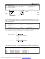
l
Mount the inverter on a metal or other noncombustible material to avoid the risk of fire.
l
l
Keep the inverter from the reach of children or persons not concerned.
Install the inverter in a safe location, avoiding high temperature, direct sunlight, humid air or
water.
The inverter can only be used at the places accredited by our company. Any unauthorized
working environment may have the risks of fire, gas explosion, electric shock and other
incidents.
l
Install a heat sink or other cooling device when installing more than one inverter in the same
enclosure so that the temperature inside the enclosure be kept below 40℃ to avoid overheat or
the risk of fire.
l
Be sure to turn off the power supply before dissembling or assembling the operation keypanel
and fixing the front cover to avoid bad contact causing faults or non-display of the operator.
l
l
Do not install the inverter in a space with explosive gas to avoid the risk of explosion.
l
Do not install any contactor and other components of capacitor or varistor on the output side of
l
the inverter. Otherwise it will cause malfunctions and damages of components of the inverter.
Do not install any switch component like air circuit breaker or contactor at the output of the
If the inverter is used at or above 1000m above seal level, the cooling efficiency will be worse,
so please run it by de-rating.
inverter. If any of such components must be installed because of the requirements of process
and others, it must be ensured that the inverter has no output when the switch acts. In addition,
5
PDF wurde mit pdfFactory Pro-Prüfversion erstellt. www.context-gmbh.de
Inverters
it is forbidden to install any capacitor for improvement of power factor or any varistor against
thunder at the output. Otherwise it will cause malfunctions, tripping protection and damages of
components of the inverter. Please remove them as shown in the below diagram.
l
It will affect the service life of the inverter if a contact is connected to the front end of input of
the inverter to control its starts and stops. Generally it is required to control it through FOR or
REV terminals. Special attention should be paid to its use in the case of frequent starts and
stops.
l
Please use an independent power supply for the inverter. Do avoid using the common power
supply with an electrical welder and other equipment with strong disturbance. Otherwise it will
cause the protection or even damage of the inverter.
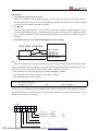
X
KM
U
Inverter V
M
W
X
2. During the Power-up
l
Danger
Do not plug the connectors of the inverter during the power up to avoid any surge into the main
control board due to plugging, which might cause the damage of the inverter.
l
Always have the protective cover in place before the power up to avoid electrical shock injury.
3. During the Operation
Danger
l
Never connect or disconnect the motor set while the inverter is in running. Otherwise it will
cause over-current trip and even burn up the main circuit of the inverter.
l Never remove the front cover of the inverter while the inverter is powered up to avoid any injury
of electric shock.
l Do not come close to the machine when the fault restart function is used to avoid anything
unexpected. The motor may automatically restart after its stop.
l
The function of STOP Switch is only valid after setting, which is different with the use of
emergent stop switch. Please pay attention to it when using it.
6
PDF wurde mit pdfFactory Pro-Prüfversion erstellt. www.context-gmbh.de
Inverters
!
Caution
l Do not touch the heat sink, braking resistor, or other heat elements. These can become very hot.
l
Be sure that the motor and machine is within the applicable speed ranges before starting
operation because the inverter is quite easy to run from lower speed to higher speed.
l Do not check the signals on circuit boards while the inverter is running to avoid danger.
l Be careful when changing the inverter settings. The inverter has been adjusted and set before exwork. Do not adjust it wantonly. Please make proper adjustments according to the required functions.
l
Do consider the vibration, noise and the speed limit of the motor bearings and the mechanical
devices when the inverter is running at or above the frequency of 50Hz.
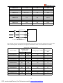
Ⅲ. Standards and Specifications
1. Particular Specifications
Type
HLPA00D423B
HLPA0D7523B
HLPA01D523B
HLPA02D223B
HLPA03D723B
HLPA05D523B
HLPA07D523B
HLPA001123B
HLPA001523B
HLPA18D523B
HLPA002223B
HLPA0D7543B
Input Voltage
Single & Three Phase
220V 50Hz
Single & Three Phase
220V 50Hz
Single & Three Phase
220V 50Hz
Single & Three Phase
220V 50Hz
Single & Three Phase
220V 50Hz
Single & Three Phase
220V 50Hz
Single & Three Phase
220V 50Hz
Single & Three Phase
220V 50Hz
Single & Three Phase
220V 50Hz
Single & Three Phase
220V 50Hz
Single & Three Phase
220V 50Hz
3Φ380V 50Hz
Power
(KW)
Inverter
Output
Capacity
Current
(KVA)
(A)
Suitable Motor
(KW)
0.4
1.0
2.5
0.4
0.75
2.0
5.0
0.75
1.5
2.8
7.0
1.5
2.2
4.4
11
2.2
3.7
6.8
17
3.7
5.5
10
25
5.5
7.5
13.2
33
7.5
11
19.6
49
11
15
26
65
15
18.5
32
80
18.5
22
38.4
96
22
0.75
2.2
2.7
0.75
7
PDF wurde mit pdfFactory Pro-Prüfversion erstellt. www.context-gmbh.de
Inverters
HLPA01D543B
3Φ380V 50Hz
1.5
3.2
4.0
1.5
HLPA02D243B
3Φ380V 50Hz
2.2
4.0
5.0
2.2
HLPA03D743B
3Φ380V 50Hz
3.7
6.8
8.5
3.7
HLPA05D543B
3Φ380V 50Hz
5.5
10
12.5
5.5
HLPA07D543B
3Φ380V 50Hz
7.5
14
17.5
7.5
HLPA001143B
3Φ380V 50Hz
11
19
24
11
HLPA001543B
3Φ380V 50Hz
15
26
33
15
HLPA18D543B
3Φ380V 50Hz
18.5
32
40
18.5
HLPA002243B
3Φ380V 50Hz
22
37
47
22
HLPA003043B
3Φ380V 50Hz
30
52
65
30
HLPA003743B
3Φ380V 50Hz
37
64
80
37
HLPA004543B
3Φ380V 50Hz
45
72
91
45
HLPA005543B
3Φ380V 50Hz
55
84
110
55
HLPA007543B
3Φ380V 50Hz
75
116
152
75
HLPA009043B
3Φ380V 50Hz
90
134
176
90
HLPA011043B
3Φ380V 50Hz
110
160
210
110
HLPA013243B
3Φ380V 50Hz
132
193
253
132
HLPA016043B
3Φ380V 50Hz
160
230
304
160
HLPA018543B
3Φ380V 50Hz
185
260
340
185
HLPA020043B
3Φ380V 50Hz
200
290
380
200
HLPA022043B
3Φ380V 50Hz
220
325
426
220
HLPA025043B
3Φ380V 50Hz
250
481
480
250
HLPA028043B
3Φ380V 50Hz
280
427
560
280
HLPA030043B
3Φ380V 50Hz
300
450
580
300
HLPA031543B
3Φ380V 50Hz
315
460
605
315
HLPA034543B
3Φ380V 50Hz
345
502
660
345
HLPA037543B
3Φ380V 50Hz
375
544
715
375
HLPA040043B
3Φ380V 50Hz
400
582
765
400
HLPA041543B
3Φ380V 50Hz
415
604
795
415
*For the power of P series:5.5KW-415KW,J series:11-55KW
2. General Specifications
Inverter Series
HLP-A
Control Mode
SPWM
Input Power
5-Digits Display &
Status Indicator
Lamp
Communication
Control
380±15% for 380V power;220±15% for 220V power
Displaying frequency, current, revolution, voltage, counter, temperature,
forward or reserve running, and fault, etc.
RS-485
8
PDF wurde mit pdfFactory Pro-Prüfversion erstellt. www.context-gmbh.de
Inverters
Operation
Temperature
Humidity
0-95% Relative Humidity(without dew)
Vibration
Below 0.5G
Range
Accuracy
Frequency Control
Setting
Resolution
Output
Resolution
Operator Setting
Method
Analog Setting
Method
Other Functions
Ramp Control
V/F Curve
Torque Control
General Control
-10~40℃
0.10~400.00Hz
Digital:0.01%(-10~40℃), Analog:0.1% (25±10℃)
Digital:0.01Hz, Analog:1‰ of Max. Operating Frequency
0.01Hz
Press directly ← ∧ ∨ to set.
External Voltage 0-5V,0-10V,4-20mA,0-20mA.
Frequency lower limit, starting frequency, stopping frequency, three skip
frequencies can be respectively set.
Selectable 4-speed steps ramp-up and -down time (0.1-6500s).
Set V/F curve at will
Torque increase is settable by max. 10.0%. The starting torque can reach
150% at 1.0Hz.
6 multi-function input terminals for 8–speed steps control, program operation,
Multi-Inputs
switching of 4-speed Ramp, UP/DOWN function, counter, external
emergency stop and other functions.
5 multi-function output terminals for displaying of running, zero speed,
Multi-Outputs
counter, external abnormity, program operation and other information and
warnings.
AVR (auto voltage regulation), Deceleration stop or free-stop, DC brake, auto
Other Functions
reset and restart, frequency track, PLC control, traverse function, drawing
control, auto energy-savings, carrier adjustable by max. 16KHz, etc.
Overload
Electronic relay protection motor
Protection
Drive(for constant torque
Protection Functions
FUSE
Protection
Over-voltage
Low Voltage
Instant Stop and
Restart
Stall Prevention
Output End
Shorts
150%/1 min. for the kinds of fan 120%/1min.)
FUSE broken, Motor stops.
DC Voltage >400V for 220V class
DC Voltage >800V for 380V class
DC Voltage <200V for 220V class
DC Voltage <400V for 380V class
Restarted by frequency track after instantaneous stop.
Anti-stall during Acc/Dec run
Electronic circuit protecting
9
PDF wurde mit pdfFactory Pro-Prüfversion erstellt. www.context-gmbh.de
Inverters
Other Functions
Fin over-heat protection, restriction of reverse running, direct start after power
on, fault reset, parameter lock PID, one-drive-more, etc.
*A part of the functions in the table are dedicated to A series, which may not available to P and
J series. For details refer to the descriptions of these functions.
Ⅳ. Storage and Installation
1. Storage
The inverter must be kept in its original package box before installation. Pay attention to the followings
when keeping it in storage if the inverter is not used for the time being:
l
It must be stored in a dry place without rubbish or dust.
l
The suitable temperature for storage is between -20℃ and +65℃.
l
The relative humidity required is 0-95% without condensation.
l
l
There is no corrosive gas or liquid in the storage ambience.
It’s better to lay the inverter on a rack and keep it in a proper package.
l
It is better not to store the inverter for long time. Long time storage of the inverter will lead to the
deterioration of electrolytic capacity. If it needs to be stored for a long time make sure to power it up
one time within a year and the power-up time should be at least above five hours. When powered up the
voltage must be increased slowly with a voltage regulator to the rated voltage value.
2. Installation Site and Environment
The inverter should be installed at the following location:
l Ambient temperature -5℃ to 40℃ with good ventilation.
l
l
l
l
l
l
No water drop and low moisture.
Free from direct sunshine, high temperature and heavy dust fall.
Free from corrosive gas or liquid.
Less dust, oil gas and metallic particles
Free from vibration and easy for service and inspection.
Free from the interference of electromagnetic noise.
Attention: The ambient conditions of the inverter will affect its service life.
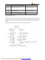
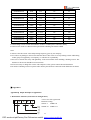
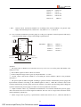
3. Installation and Direction
l
l
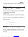
l
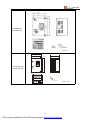
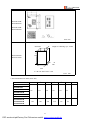
There must be enough space left around the inverter for easy maintenance and cooling. See Diagram 1.
The inverter must be installed vertically with the smooth ventilation for effective cooling.
If there is any instability when installing the inverter, please put a flat board under the inverter bottom
base and install it again. If the inverter is installed on a loose surface, stress may cause damage of parts
l
in the main circuit so as to damage the inverter.
The inverter should be installed on non-combustible materials, such as iron plate.
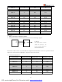
l
If several inverters are installed, upper and lower, together in one cabinet, please add heat dissipation
plates and leave enough space between the inverters. See Diagram.
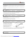
10
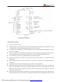
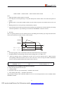
PDF wurde mit pdfFactory Pro-Prüfversion erstellt. www.context-gmbh.de
120
Inverters
50
50
120
!
UNIT: mm
Ⅴ. Wiring
1. Main Circuit Wiring Schematic Diagram
Power supply:
l
Verify that the inverter’s rated voltage coincides with AC power supply
voltage to avoid a damage of the inverter.
No fuse breaker:
l
Refer to the related list.
Ground fault circuit interrupter:
l
Use one of anti-high harmonic.
Electromagnetic contactor:
l
Note: Do not use the electromagnetic contactor as the on/off button of power
supply for the inverter.
AC reactor:
l
It is recommended to install an AC reactor for power factor improvement if
the input capacity is more than 1000KVA.
Inverter:
l
Be sure to make correct connections of the main circuit wires and control
signal wires of the inverter.
l
Be sure to make correct setting of parameters for the inverter.
11
PDF wurde mit pdfFactory Pro-Prüfversion erstellt. www.context-gmbh.de
Inverters
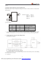
2. Description of Terminal Block
1)Arrangement of Main circuit Terminals
HLPA00D423B-HLPA01D523B
HLPA0D7543B-HLPA02D243B
E
R
S
T
U
HLPA03D743B
HLPA02D223B-HLPA03D723B
E
R
S
T
U
HLPA05D543B-HLPA07D543B
E
HLPA001143B~HLPA003043B
HLPA05D523B-HLPA07D523B
R
HLPA003743B-HLPA016043B
HLPA18D523B-HLPA002223B
R
P1
+
-
R
R
S
S
T
S
S
T
P
E
E
P
U
W
V
V
E
T
T
U
V
W
PR
P
PR
PR
W
P1
P
N
U
V
P1
V
P+
N
U
W
Cabinet HLPA016043B-HLPA041543B
2)Arrangement of Control Circuit Terminals
FA
KA
FB
FC
KB
EV
UPF
SPL
DRV
SPM
+10
HLPA00D423B~HLPA01D523B
FA
SPH
FB
FC
RST
KA
REV
KB
FOR
SPH
RST
DCM
REV
FOR
AI
ACM
AM
RS-
RS+
SPL
SPM
RS-
RS+
VI
HLPA0D7543B~HLPA02D243B
EV
+10
UPF
VI
HLPA03D743B~HLPA041543B
DRV
AI
ACM
DCM
AM
HLPA001123B~HLPA002223B
12
PDF wurde mit pdfFactory Pro-Prüfversion erstellt. www.context-gmbh.de
V
W
W
Inverters
FA
SPH
FB
RST
FC
KA
REV
KB
FOR
P24
+10
UPF
VI
DRV
AI
DCM
XI
SPL
ACM
SPM
V0
A0
HLPA05D523B~HLPA07D523B
3)Function Description of Main circuit Terminals
Symbol
R.S.T
Function Description
Input terminal of AC line power. ( 220V class, for both single/three phase,
single phase connected to any two phases)
U.V.W
Output terminal of the inverter
P.Pr
Connector for braking resistor.
P1P
P(+)、N(-)
E
Connector for DC reactor (When using a DC reactor the jumper shall be
removed. A05D543B and A07D543B internally jumped)
Connecting terminal of external braking bank.
Ground terminal: the third method of grounding for 220V and special
grounding for 380 V of Electrical Engineering Regulations.
4)Function Description of Control Circuit Terminals
Symbol
Function Description
Factory setting
FOR
Multi-Input 1
Forward run
REV
Multi-Input 2
Reverse run
RST
Multi-Input 3
Reset
SPH
Multi-Input 4
High speed
SPM
Multi-Input 5
Middle Speed
SPL
Multi-Input 6
Low Speed
Common Terminal of Digital and Control
DCM
Signals, +12v Power, (EV、IPV、P24)
Ground
EV(IPV)
+12V Power Supply
Max. output current 200mA
P24
+12V Power Supply
Max. output current 200mA
+10
Power Supply for Speed Setting
+10V
VI
AI
Analog Voltage Frequency
corresponding
highest operating frequency
Analog Current Frequency Reference
4~20mA
Input
highest operating frequency
Analog Input
AO
Output current
VO
Output voltage
DRV
0~+10V
Input
XI
ACM
Reference
corresponding
Common Terminal of Analog and Control
Signals
Multi-Output 1 (Optical couple output)
DC24V/100mA
13
PDF wurde mit pdfFactory Pro-Prüfversion erstellt. www.context-gmbh.de
to
the
to
the
Inverters
UPF
Multi-Output 2 (Optical couple output)
FA(EFA)
、
FB(EFB)、
Multi-Output 3 (N/O or N/C)
3A/250VAC、3A/30VDC
Multi-Output 4 (N/O)
3A/250VAC,3A/30VDC
Output terminals of digital frequency
0~10V
FC(EFC)
KA(EKA)、
KB(EKB)
AM
RS+ RS-
RS485 Communication port
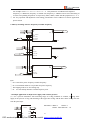
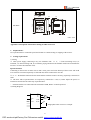
3. Basic Connection Diagram
The wiring of the inverter is divided into two parts, main circuit terminal connections and control circuit
terminal connections. The user can see the main circuit terminals, and the control circuit terminals after
removing the cover of enclosure. The terminals must be connected correctly as the following wiring circuit
diagrams.
The following diagram shows the factory standard connection of Model HLP-A
14
PDF wurde mit pdfFactory Pro-Prüfversion erstellt. www.context-gmbh.de
Inverters
15
PDF wurde mit pdfFactory Pro-Prüfversion erstellt. www.context-gmbh.de
Inverters
4. Precautions on Wiring
1)
For the main circuit wiring:
l
While wiring the sizes and specifications of wires should be selected and the wiring should be executed
according to the electrical engineering regulations to ensure the safety.
l
It is better to use shielded wire or wire and conduit for power cord and ground the shielded layer or two
ends of wire conduit.
l
Be sure to install a Non Fuse Breaker (NFB) between the power supply and the input terminals (R.S.T).
l
(If using ground fault circuit interrupter, please choose one corresponding to high frequency)
Never connect AC power to the output terminal (U.V.W) of the inverter.
l
Output wires mustn’t be in touch of the metal part of the inverter enclosure, or it will result in earth
l
short-circuit.
Phase-shifting capacitors, LC, RC noise filters, etc, can never be connected to the output terminals of
the inverter.
l
l
The main circuit wire must be enough far away from other control equipments.
When the wiring between the inverter and the motor exceeds 15 meters for 220V class or 30 meters for
380V class, much higher dV/dT will be produced inside the coil of the motor, which will cause the
destruction to the interlay or insulation of the motor. Please use a dedicated AC motor for the inverter or
add a reactor at the inverter.
l
Please lower the carrier frequency when there is a longer distance between the inverter and the motor.
Because the higher the carrier frequency is the bigger the leakage current of high-order harmonics in the
16
PDF wurde mit pdfFactory Pro-Prüfversion erstellt. www.context-gmbh.de
Inverters
cables will be. The leakage current will have unfavorable effect on the inverter and other equipment.
Specifications of Non Fuse Breaker and Wire
NFB(A)
Input wire
mm2
Output wire
mm2
Control
wire mm2
Screw
HLPA00D423B
16
2.5
2.5
1
M4
HLPA0D7523B
16
2.5
2.5
1
M4
HLPA01D523B
32
2.5
2.5
1
M4
HLPA02D223B
32
4
4
1
M4
HLPA0D7543B
16
2.5
2.5
1
M4
HLPA01D543B
16
2.5
2.5
1
M4
HLPA02D243B
16
2.5
2.5
1
M4
HLPA03D743B
16
2.5
2.5
1
M4
HLPA05D543B
32
4
4
1
M5
HLPA07D543B
40
6
6
1
M5
HLPA001143B
63
6
6
1
M6
HLPA18D543B
100
10
10
1
M6
HLPA002243B
100
16
16
1
M8
HLPA003043B
160
25
25
1
M8
HLPA003743B
160
25
25
1
M8
HLPA004543B
200
35
35
1
M10
HLPA005543B
200
35
35
1
M10
HLPA007543B
250
70
70
1
M10
HLPA009043B
315
70
70
1
M10
HLPA011043B
400
95
95
1
M12
HLPA013243B
400
150
150
1
M12
HLPA016043B
630
185
185
1
M12
HLPA020043B
630
240
240
1
M16
HLPA022043B
800
150×2
150×2
1
M16
HLPA025043B
800
150×2
150×2
1
M16
HLPA028043B
800
150×2
150×2
1
M16
HLPA030043B
800
150×2
150×2
1
M16
HLPA031543B
1000
185×2
150×2
1
M16
HLPA034543B
1000
185×2
150×2
1
M16
HLPA037543B
1200
240×2
185×2
1
M16
Model
17
PDF wurde mit pdfFactory Pro-Prüfversion erstellt. www.context-gmbh.de
Inverters
HLPA040043B
1200
240×2
185×2
1
M16
HLPA041543B
1200
240×2
185×2
1
M16
Mark: * The parameters in the list are only for reference and should not be regarded as standard.
*The configurations of P and J series P are the same to A series, which can be referred.
2) For control circuit wiring (signal line)
l
The signal line should be separately laid in a different conduit with the main circuit wire to avoid any
possible interference.
l
Please use the shielded cable with the size of 0.5-2mm2 for signal lines.
l
Use the control terminals on the control panel correctly according to your needs.
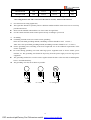
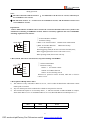
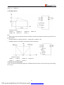
3) Grounding
l
Grounding terminal E. Be sure to make correct grounding
220V class: The third grounding method (Grounding resistance should be 100Ω or lower.)
380V class: The special third grounding method (Grounding resistance should be 10Ω or lower.)
l
Choose grounding wires according to the basic length and size of the technical requirements of the
l
electric equipment.
Do avoid sharing grounding wire with other large power equipment such as electric welder, power
machine, etc. The grounding wire should be kept away from the power supply wires for large power
l
equipment.
The grounding method for several inverters together should be done as the first and second diagrams
below. Avoid the third loop.
l
The grounding wire must be as shorter as possible.
(1)Good
(2)Good
(3)Not good
18
PDF wurde mit pdfFactory Pro-Prüfversion erstellt. www.context-gmbh.de
Inverters
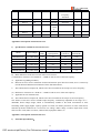
Ⅵ. Instruction of the Digital Operator
1. Description of the Digital Operator
Main Display Zone
LED Display Zone
indicating frequency,
FOR
indicating For.,
REV
HZ
A
R/min
current, AC V, DC V,
Rev., frequency,
revolution, counter,
current,
temperature, etc.
revolution, etc.
FOR/REV Switch
Value change key
F /
R
Shift key
PROG
Function key
ENTER
Par.set key
STOP
Run key
RUN
Stop/Reset key
RESET
HLKD0002
LED Display Zone
indicating For.,
Main Display Zone
FOR
REV
HZ
A
ROTT
indicating frequency,
Rev., frequency,
current, AC V, DC V,
current, rev.,
revolution, counter,
etc.
temperature, etc.
FOR/REV Switch
FOR
REV
PROG
DISP
SET
Value change key
Shift key
Run key
RUN
STOP
Function key
Par.set key
Stop/Reset key
HLKD0001
Note: The panel type of C series is OP-AC01
*The panels of P and J series are the same to A series
with the type of OP-AB02, which can be interchanged
with OP-AB01.
2. Description of Indicator Lamp Status
1) Description of Indicator Lamp Status
Indicator lamp
Status
Description
FOR
on
The motor is in forward rotation.
REV
on
The motor is in reverse rotation.
HZ
on
Displaying set frequency or output frequency.
19
PDF wurde mit pdfFactory Pro-Prüfversion erstellt. www.context-gmbh.de
Inverters
A
on
Displaying output current.
ROTT
on
Displaying rated motor revolution
A ROTT
on
Displaying AC or DC voltage.
HZ ROTT
on
Displaying counting value.
HZ A ROTT
on
Displaying internal temperature of the inerter.
2) Description of Display Items
Display
Indic.lamp
on
Meaning
Present output frequency is 50.00HZ
Present set frequency is 50.00HZ
Present output current is 3.0A
Present output revolution is 1440r/min
Present DC voltage is 510.1V
Present AC voltage is 380.0V
Present inverter’s temperature is 35.0℃
Present counter’s value is 105
Present target value of PID is 50.0%
Present
I feedback value of PID is 48.0%
Present time of power-on is 12 hours
Total run time of inverter is 108 hours
3. Description of Operation Examples
Procedures
Display
Power up,
Operation of
power
Dsp2.0 flash
Vr2.00
000.00
PROG
ENYER
ENTER
PROG
RUN
Indicator
Lamp
Explanation
FOR
¢
HZ
¤
Self detect when power-up, display
version no. (Flashing) and finally set
frequency.
FOR
¢
HZ
¤
Enter programming
Display the function of CD000
000.00
FOR
¢
HZ
¤
Display the contents of CD000
50.00
END
50.00
CD001
050.0
FOR
¢
FOR
¢
HZ
¤
HZ
¤
Change the content of CD000
Confirm changed value.
Display END 50.00 CD001
Back from programming
50.00
FOR
¤
HZ
¤
Display running and operating
frequency
50.00
FOR
HZ
Monitor screen switching, display outp
CD000
20
PDF wurde mit pdfFactory Pro-Prüfversion erstellt. www.context-gmbh.de
Inverters
0.00
5 0.00
DISP
005.0
PROG
01440
DISP
ut current
FOR
¤
HZ
¤
Monitor screen switching, display
output current
A
¤
Monitor screen switching, display
revolution
FOR
¤
FOR ROTT
¤
¤
Switch back to main screen, display set
frequency
50.00
FOR
¤
HZ
¤
Switch of For.Rev. rotation, display the
status of Rev rotation
050.0
FOR
¤
HZ
¤
Switch to adjustable frequency
030.00
FOR
¤
HZ
¤
Adjust set frequency, i.e. the value of
CD000
FOR
¤
HZ
¤
Confirm changed value, write to
CD000 as value
FOR
¢
HZ
¤
Stop
F/R
030.00
30.00
STOP
¤
50.00
PROG
ENTER
¤
Note:
①
means flashing.
¤ means bright.
② With HLKD0001 and HLKD0002 the functions of ENTER and SET are the same, and the functions of
PROG and FUNC are the same.
③ For monitoring AC, DC, T and other items they can be only switched and displayed after the parameter
setting.
④ When it is powered up again after a power breakdown the inverter will display the screen previous to
the power breakdown after its self detection.
21
PDF wurde mit pdfFactory Pro-Prüfversion erstellt. www.context-gmbh.de
Inverters
Ⅶ. Commissioning
1. Important Checks before the Commissioning
l
If there is any wrong connected wires? Pay special attention to the terminal of U.V.W; Make sure the
power supply wires are connected to R.S.T, not U.V.W.
l
If there is any metal powder or wires left on the base plate of the inverter or the terminal block, which
may cause short circuit.
l
If screws are tightly locked and if the connecting parts are loose.
l
If there is any short circuit or earth fault at outputs.
2. Commissioning Methods
The procedure of the operator is factory set up for the control mode of HLP series. The commissioning can
be carried out through the digital operator. Generally, the commissioning can be conducted at 5.00 Hz.
Procedures
Power up
Display
Indicator Lamp
dsp1.1→Vr2.0
FOR Hz
¤
↓
Explanation
Self detect when power up,
display version no. and finally
set frequency
FOR Hz
△
¤
↓
FOR Hz
←△
¤
↓
FOR Hz
¤
ENTER
↓
FOR Hz
¤
RUN
↓
¤
FOR Hz
¤
STOP
Switch to adjustable
frequency on the panel
Change set frequency, i.e. the
value of CD000
Confirm changed value
Run at 50Hz
Stop
Note: ¤ means indicator lamps is on;
means indicator lamps flash; means digits flash.
* With OP-AB01 and AB02 the functions of ENTER and SET are the same.
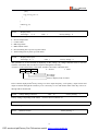
3. Description of Panel Type:
OP
A
B
01
01: Small panel
02: Big panel
03: Panel for C series
B: B version
C: C version
A: A series
C: C series
OP:OPERATOR
22
PDF wurde mit pdfFactory Pro-Prüfversion erstellt. www.context-gmbh.de
Inverters
Note:
1: The panel type for B version of A series is OP-AB01.
2: The panel type for C version of A series is OP-AC01.
3: The big panel type for B version of A series is OP-AB02.
4: The panels of OP-AB01and OP-AB02 are interchangeable.
5: Notice the panels of B version and C version are not interchangeable.
6: Notice the panels of A series and C series are also not interchangeable.
23
PDF wurde mit pdfFactory Pro-Prüfversion erstellt. www.context-gmbh.de
Inverters
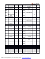
Ⅷ. Function List
Parameter and Function List (Part 1)
Categ
ory
Code
Function
CD000
Main Frequency
0.00~400.00 Hz
CD001
Max. Voltage
0.1V—*
CD002
Base Frequency
0.01~400.00 Hz
CD003
Intermediate Voltage
0.1V—*
CD004
Intermediate
Factory
Setting
0.00
220/380
50.00
*
0.01~400.00 Hz
Frequency
2.50/3.0
CD005
Min. Voltage
0.1~50.0V
CD006
Min. Frequency
0.01~20.00 Hz
0.50
CD007
Max Operating
50.00~400.00 Hz
50.00
0.00~400.00 Hz
0.00
Frequency
Basic Parameters
Set Range & Function Explanation
CD008
Reserved
CD009
Frequency Lower
Limit
0:Invalid
*
CD010
Parameter Lock
CD011
Parameter Reset
CD012
Accel. Time 1
0.1~6500.0S
*
CD013
Decel. Time 1
0.1~6500.0S
*
CD014
Accel. Time 2
0.1~6500.0S
*
CD015
Decel. Time 2
0.1~6500.0S
*
CD016
Accel. Time 3
0.1~6500.0S
*
CD017
Decel. Time 3
0.1~6500.0S
*
CD018
Accel. Time 4
0.1~6500.0S
*
CD019
Decel. Time 4
0.1~6500.0S
*
00~10
1:Valid
08:Restore the factory setting.
No other function.
0
00
CD020
∫
Reserved
Applicable Parameters
CD030
0:Start from Starting Frequency
CD031
Starting Mode
CD032
Stopping Mode
CD033
CD034
1:Frequency track start
0:Decelerating stop
1:Coasting stop
Source of Run
0:Operator
Commands
2:Communication port
Source of Operating 0:Operator
Frequency
1:External terminal
1:External terminal
2:Communication port
CD035
Carrier frequency
0~15
CD036
Jogging Frequency
0.00~400.00 Hz
0
0
0
0
*
Parameter and Function List (Part 2)
24
PDF wurde mit pdfFactory Pro-Prüfversion erstellt. www.context-gmbh.de
5.00
Inverters
Catego
Input and Output Terminals
Applicable Parameters
ry
Code
Functions
Set Range & Function Explanation
0: Rev Run forbidden; 1:Rev Run
Factory
Setting
CD037
Rev. Rotation Select
CD038
STOP key select
0:STOP Invalid 1:STOP Valid
1
CD039
S-Curve Time
0~6500S
0
CD040
Reserved
CD041
Starting Frequency
0.1~10.0 Hz
0.5
CD042
Stopping Frequency
0.1~10.0 Hz
0.5
CD043
Auto Torque Compensation 0-10.0%
2.0%
CD044
Skip Frequency 1
0.00~400.00 Hz
0.00
CD045
Skip Frequency 2
0.00~400.00 Hz
0.00
CD046
Skip Frequency 3
0.00~400.00 Hz
0.00
CD047
Skip Frequency Range
0.00~2.00 Hz
0.5
CD048
Timer 1 time
0~10.0
0.01
CD049
Timer 2 time
0~100
0.01
*CD050
Multi-input 1(FOR)
0: Invalid; 1:Run; 2: For rotation; 3:
02
*CD051
Multi-input 2(REV)
Rev rotation; 4: Stop; 5: FOR/REV.;
03
*CD052
Multi-input 3(RST)
6: Jog; 7: Jog For rotation; 8: Jog
Rev Rotation; 9: Emergent stop; 10:
10
*CD053
Multi-input 4(SPH)
Reset; 11:Reserved; 12: Overheat of
17
*CD054
Multi-input 5(SPM)
heat sink or motor; 17: High speed;
Middle speed; 19: Low speed; 20:
18
Enable
1
0.01
Multi-speed 1; 21: Multi-speed 2; 22:
*CD055
Multi-input 6(SPL)
Multi-speed 3; 23: Ramp select 1; 24:
Ramp select 2; 25: UP function; 26:
19
DOWN function; 27: Counter 28:
Counter reset; 29: Drawing; 32: PID
Start
*CD056
*CD057
*CD058
Multi-output 1(DRV)
Multi-output 2(UPF)
Multi-output 3(Terminals
0: Invalid; 1: Run; 2: Fault indication;
3: Zero Speed; 4: Braking
indication; 5: Set Frequency reach; 6:
Arbitrary Frequency 1 reach;
of FA,FB,FC)
01
05
02
Parameter and Function List (Part 3)
Categ
Code
Functions
Set Range & Function Explanation
25
PDF wurde mit pdfFactory Pro-Prüfversion erstellt. www.context-gmbh.de
Factory S
Inverters
ory
etting
7: Arbitrary Frequency 2 reach; 8:
In Accel.; 9: In Decel.; 10: Inverter
Overload
alarm;
11:
Motor
Overload alarm; 12: Over-torque
*CD059
Multi-output 4(Terminals
of KA,KB)
alarm; 13: Low voltage alarm; 14:
Single stage end indication; 15:
00
Process end indication; 16: Counter
reach; 27: Drawing reach;
28:PID
lower limit alarm; 29: PID upper
limit alarm; 30: Fan act; 31:
Input and Output Terminals
Reserved; 32: Braking resistor act
CD060
Multi-output 5(AM)
Output of digital frequency signals
CD061
Uniform Frequency 1
0.00~400.00 Hz
0.00
CD062
Uniform Frequency 2
0.00~400.00 Hz
0.00
CD063
Uniform Frequency Range
0.10~10.00 Hz
0.50
CD064
Counting value set
00~65500
00
CD065
Analog Input
0~10
0
CD066
Lower Analog Frequency
0.00~400.00 Hz
CD067
Bias Direction at Lower
0:Positive direction
CD068
Frequency
Higher Analog Frequency
direction
0.00~400.00 Hz
CD069
Bias Direction at Higher
0:Positive direction
Frequency
direction
Analog Negative Bias
Reverse
0:Not allowable.
0
0
1:Negative
50.00
0
1:Allowable.
0
CD071
AM Analog output Gain
0.0~100.0%
100
CD072
Up/Down Function
0:Not memorized
CD073
Up/Down Speed
0:0.01HZ
CD074
Analog Filtering Constant
0~50
20
CD075
Intermediate Counter
0~65500
0
1:Memorized
1:0.1HZ
1
0
0:Normal run; 1: External control 4
PLC
and Simple
Multi-speed
CD070
1:Negative
0
CD076
PLC Operation
-speed; 2:External control multispeed; 3: Disturbance; 4: Internal
control multi-speed; 5: Drawing
0
Parameter and Function List (Part 4)
Categ
ory
Code
Functions
Set Range & Function Explanation
26
PDF wurde mit pdfFactory Pro-Prüfversion erstellt. www.context-gmbh.de
Factory
Setting
Inverters
0:Stop after running for one cycle;
1:Cycling run; 2:Auto stop after
CD077
AutoPLC
running for one cycle (STOP for
0
intervention); 3: Auto Run and
Cycling (STOP for intervention)
PLC rotation Direction
0~255
CD079
PLC Ramp Time
0~65535
CD080
Frequency 2
0.00-400.00 Hz
15.00
PLC
CD081
Frequency 3
0.00-400.00 Hz
20.00
CD082
Frequency 4
0.00-400.00 Hz
25.00
Multi-speed and Simple
(0:For
CD078
CD083
Frequency 5
0.00-400.00 Hz
30.00
CD084
Frequency 6
0.00-400.00 Hz
35.00
CD085
Frequency 7
0.00-400.00 Hz
40.00
CD086
Frequency 8
0.00-400.00 Hz
0.50
CD087
Timer 1
0.0-6500.0S
10.0
CD088
Timer 2
0.0-6500.0S
10.0
CD089
CD090
Timer 3
Timer 4
0.0-6500.0S
0.0-6500.0S
0.0
0.0
CD091
Timer 5
0.0-6500.0S
0.0
CD092
CD093
Timer 6
Timer 7
0.0-6500.0S
0.0-6500.0S
0.0
0.0
CD094
Timer 8
0.0-6500.0S
0.0
CD095
AutoPLC Memory
0~1
0
0~2
0
1~9000mim
1
1~250s
5s
CD096~
CD109
Number of Auxiliary Pump
CD111
Continuous Operating Time
of Aux. Pumps
Multi-speed and Easy PLC
0
0
Reserved
CD110
CD112
1:Rev)
Interlocking Time of Aux.
Pumps
CD113
High Speed Running Time
1~250s
60s
CD114
Low Speed Running Time
1~250s
60s
CD115
Stopping Voltage Level
1~150%
95%
CD116
Lasting Time of Stopping
1~250s
30s
Voltage Level
CD117
Wakeup Level
1~150%
80%
CD118
Sleep Frequency
0.00~400.0
20.00
CD119
Lasting
Time
of
Frequency
Sleep
1~250s
20s
Parameter and Function List (Part 5)
Categ
ory
Code
Functions
Set Range & Function Explanation
27
PDF wurde mit pdfFactory Pro-Prüfversion erstellt. www.context-gmbh.de
Factory
Setting
Inverters
Parameters of Protection Functions
Over-voltage Stall Prevention
0:Invalid
CD120
Stall Prevention Level at
CD121
Accel.
CD122
Stall Prevention Level at 0~200%
1:Valid
0~200%
1
150
0
Constant Speed
CD123
Stall Prevention Level at 0~200%
150
Decel.
CD124
Over-torque Detect Mode
CD125
Over-torque Detect Level 0~200%
CD126
Over-torque Detect Time
CD127
CD128
CD129
Decel.
time
prevention
for
0~3
0.1~20.0S
0
0
1.0
5.0
stall
at constant
speed
1.0
Fault restart time
0.5
Voltage rise time during
frequency track
Parameters of Motor Functions
CD130
Rated Motor Voltage
*
Set according to Motor nameplate
CD131
Rated Motor Current
Set according to Motor nameplate
*
CD132
Motor pole number.
02—10
00—9999
04
CD133
Rated Motor Revolution
CD134
Motor no-load current
0—99
40
CD135
Motor slip compensation
0.0—10.0
0.0
0.0~20.0%
2.0
0.0~25.0S
0.0
0.0~25.0S
0.0~20.0S
0.0
5.0
0~200%
150
CD136~
CD139
CD140
CD141
CD142
CD143
CD144
1440
Reserved
DC Braking level
DC Braking time at start
DC Braking time at stop
Frequency track time
Current
level
frequency track
for
Parameter and Function List (Part 6)
Categ
ory
Code
Functions
Set Range & Function Explanation
28
PDF wurde mit pdfFactory Pro-Prüfversion erstellt. www.context-gmbh.de
Factory
Setting
Inverters
Restart
CD145
CD146
Parameters of Special Functions
CD147
CD148
CD149
after
Instantaneous Stop
0:Invalid
Power- 0.1~5.0S
Allowable
Breakdown Time
Number
1:Frequency track
of
Restart
0
0.5
0—10
Abnormal 0:Invalid
0~10%
00
1:Valid
1
0
Auto Voltage Regulation
Auto Energy Saving
CD150
Proportional Constant (P)
0.0~1000.00%
100%
CD151
Integral Time (I)
0.1~3600.00S
5.0
CD152
Differential Time (D)
0.01~10.00S
0
CD153
Target value
0.0~100.0%
0
CD154
Target value select
0: set by the operator
1:set by
0
external terminals(0-10V)
CD155
PID upper limit
0~100%
100%
CD156
PID lower limit
0~100%
0%
Monitoring Parameters
Communication Functions
CD157~
CD159
Reserved
CD160
Communication
0-250
0
0-3
0-5
1
0
Addresses
CD161
CD162
Communication Baud Rate
Communication Data
Method
CD163~
CD166
Reserved
CD167
Display Items
0-5
CD168
Display Items Open
0-7
0
CD169
Voltage Rating of
Inverter
Set according to the model
0
Rated Current of
Set according to the model
*
*
CD170
Inverter
CD171
Software Version
CD172
Fault Record 1
CD173
CD174
Fault Record 2
Fault Record 3
CD175
Fault Record 4
CD176
Fault Clear
*
——
Note: —— means no fault record.
——
——
——
00—10
(01 for Fault Clear)
00
Parameter and Function List (Part 7)
Categ
ory
Code
Functions
Set Range & Function Explanation
29
PDF wurde mit pdfFactory Pro-Prüfversion erstellt. www.context-gmbh.de
Factory
Setting
Inverters
Factory Setting
CD177
CD178
Inverter Model
Inverter Frequency
Standard
CD179
Manufacture Date
CD180
Serial No.
CD181~
CD250
0:50Hz 1:60Hz
0
Year:Month:Week
*
*
Reserved
Note: ① The above functions with the mark of ﹡ are dedicated to the inverter of A
series, which or part of which may be not available for P or J series.
② The functions of above CD076 and CD077 are not available for P series, and
the functions of above CD011, CD019 and CD150-CD156 are not available for J
series.
Ⅸ. Descriptions of Functions
CD000 Main Frequency
**
30
PDF wurde mit pdfFactory Pro-Prüfversion erstellt. www.context-gmbh.de
Inverters
Set Range:0.00—400.00 Hz
Unit:0.01 Hz
Factory Setting:0.00
In the digital operator mode, the inverter will run at the set value of CD000. During running, the operating
frequency can be changed by pressing ▲ or ▼. During multi-speed running, the main frequency is taken
as the frequency of Speed 1.
In the external control multi-speed mode, if CD034 is set to 1, i.e. given by an external terminal, Speed 1
will be given by the analog of the external terminal.
The setting of main frequency is limited by the maximum operating frequency.
The related parameters of CD034, CD076 are adjustable during operation.
CD001 Max. Voltage
Set Range:0.1—*
Unit:0.1V
Factory Setting:220/380V
This parameter should be set according to the rated value of the motor’s nameplate. The factory setting is
380V for 380V class motor and 220V for 220V class motor. The setting range of this parameter is restricted
by the voltage rating of the inverter. In case of the motor relatively far away from the inverter this set value
can be increased properly.
CD002 Base Frequency
Set Range:0.01—400.00 Hz Unit:0.1Hz
Factory Setting:50.00
This parameter must be set according to the rated frequency of operating voltage on the motor’s nameplate.
Under normal conditions do not change the set value of base frequency at will. If it is equipped with a special
motor this value should be set properly according to the characteristics of the motor’s parameters. Otherwise
it may cause the damage to the equipment.
CD003 Intermediate voltage
Set Range:0.1—500.0V
Unit:0.1V
Factory Setting:15/27.5
This parameter is set for an intermediate voltage value of arbitrary V/F curve. If it is set improperly, it will
cause over-current or under-torque of the motor, or even tripping of the inverter. When the intermediate
frequency is increased the voltage will increase the output torque and at the same time also the output current.
When changing this parameter please pay attention to monitoring the output current to avoid the inverter’s
tripping due to over-current.
The factory setting of intermediate voltage for 220V class inverter is 15, while the factory setting of
intermediate voltage of 380V class inverter is 27.5.
This set value of intermediate voltage is limited by the set value of max voltage. When the voltage is
increasing to a certain value at intermediate frequency the torque compensation will lose its function. When
adjusting this parameter the output current of the inverter should be increased from low to high slowly
according to the load of machines until it meets the starting requirement. Do not be quick to increase it by
large amplitude. Otherwise it might cause the tripping of the inverter or the damage of the machines.
CD004 Intermediate Frequency
31
PDF wurde mit pdfFactory Pro-Prüfversion erstellt. www.context-gmbh.de
Inverters
Set Range:0.01—400.00 Hz
Unit:0.01 Hz
Factory Setting:2.50
Note: ** means this parameter is adjustable during operation.
This parameter is set for intermediate frequency of arbitrary V/F curve. If it is set improperly, it will cause
over-current or under-torque of the motor, or even tripping of the inverter.
This set value of intermediate frequency is limited by the set value of base frequency.
CD005 Min. Voltage
Set Range:0.1—50.0V
Unit:0.1V
Factory Setting:*
This parameter is set for the min. starting voltage of V/F curve.
The factory setting of min. voltage for 220V class inverters is 8, and the factory setting of min.voltage for
380V class inverters is 13.5.
This set value is limited by the voltage at the max. frequency.
CD006 Min. Frequency
Set Range:0.1—20.00 Hz
Unit:0.01 Hz
Factory Setting:0.50
This parameter is set for the min. starting frequency of V/F curve.
The following table has specific factory settings of V/F curve, accel./decal., time and carrier for the inverter
of A series:
Code
Model
CD003CD005CD012CD013CD035
Code
Model
CD003CD005CD012CD013CD035
A00D423B 15.0
7.5
5
5
9
A003043B 17
8.5
30
30
4
A0D7523B 14.0
7
8
8
9
A003743B 16
8
35
35
4
A01D523B 14.0
7
10
10
8
A004543B 16
8
40
40
4
A02D223B 13.0
6.5
10
10
8
A005543B 15
7.5
45
45
3
A03D723B 13.0
6.5
15
15
7
A007543B 15
7.5
50
50
3
A05D523B 12.0
6.0
15
15
6
A009043B 14
7
75
75
2
A07D523B 11.0
5.5
20
20
6
A011043B 14
7
100
100
2
A001123B 10.0
5.0
25
25
5
A013243B 13
6.5
150
150
2
A001523B 10.0
5.0
30
30
5
A016043B 13
6.5
150
150
2
A18D523B 9.0
4.5
35
35
5
A018543B 12
6
200
200
2
A002223B 9.0
4.5
50
50
4
A020043B 12
6
200
200
2
A0D7543B 22
11
8
8
9
A022043B 11
5.5
250
250
2
A01D543B 22
11
10
10
8
A025043B 11
5.5
250
250
2
A02D243B 21
10.5
15
15
8
A028043B 11
5.5
250
250
2
A03D743B 21
10.5
15
15
7
A030043B 10
5
250
250
2
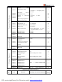
A05D543B 20
10
15
15
6
A031543B 10
5
250
250
2
A07D543B 20
10
20
20
6
A034543B 10
5
250
250
2
A001143B
19
9.5
20
20
5
A037543B 10
5
250
250
2
A001543B
19
9.5
20
20
5
A040043B 10
5
250
250
2
A18D543B 18
9
25
25
5
A041543B 10
5
250
250
2
A002243B
9
25
25
5
18
32
PDF wurde mit pdfFactory Pro-Prüfversion erstellt. www.context-gmbh.de
Inverters
Note: ①Ramp Time 2 = Ramp Time 1 x 2
②Ramp Time 3 = Ramp Time 2 x 2
③Ramp Time 4 = Ramp Time 3 x 2
④Min.Voltage Value = Intermediate Voltage Value/2
⑤The intermediate frequency is 2.5 for the system of 50Hz.
⑥The intermediate frequency is 3.0 for the system of 60Hz.
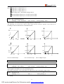
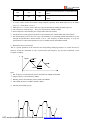
CD007 Max. Operating Frequency
Set Range:10.00—400.00 Hz
Unit:0.01 Hz
Factory Setting:50.00
This parameter is set for the maximum operating frequency of the inverter.
The following are several curves and set values often used for reference. Specific curves must be set
according to concrete characteristics of mechanical load.
220
220
220
15
55
24
8
8
9
0.5 2.5
50
220
0.5
25
0.5
50
220
220
27.5
110
45
13.5
16
20
0.5 2.5
50
Curve of constant torque
0.5
25
0.5
50
Curve of lower torque
25
50
2.5
50
Curve of higher torque
CD008 Reserved
CD009 Frequency Lower Limit
Set Range:0.00—400.00
**
Unit:0.01 Hz
Factory Setting:0.00
This is set for preventing workers from false operation to avoid over-heat or some other mechanical faults,
which might be caused due to too low operating frequency.
The setting of Frequency Lower Limit must be less than the set value of Frequency Upper Limit.
CD010 Parameter Lock
Set Range:0—1
Unit:1
**
Factory Setting:0
0: Invalid.
33
PDF wurde mit pdfFactory Pro-Prüfversion erstellt. www.context-gmbh.de
Inverters
1: Valid, i.e. the parameters are locked. Except this parameter other parameters can not be changed.
This parameter is set to prevent non-maintenance personnel from setting other parameters by mistake. After
the parameters are locked the operating frequency can be changed by pressing △ or ▽.
CD011 Parameter Reset
Set Range:00—10
Unit:1
Factory Setting:00
When the value for a parameter is set improper or is abnormal for some reasons this parameter can be set to
08 to restore it to the factory setting and then reset. After the parameters are locked (in case of CD010=1) the
parameters can’t be reset. They can only be reset after unlock. For related parameters refer to CD010.
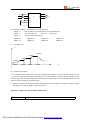
CD012 Accel. Time 1
**
Set Range:0.1—6500.0S
Unit:0.1S
Factory Setting:
CD013 Decel. Time 1
*
**
Set Range:0.1—6500.0S
Unit:0.1S
Factory Setting:
CD014 Accel. Time 2
*
**
Set Range:0.1—6500.0S
CD015 Decel. Time 2
Set Range:0.1—6500.0S
Unit:0.1S
Factory Setting:
*
Unit:0.1S
**
Factory Setting:
*
CD016 Accel. Time 3
**
Set Range:0.1—6500.0S
CD017 Decel. Time 3
Unit:0.1S
Factory Setting:
**
*
Set Range:0.1—6500.0S
Unit:0.1S
Factory Setting:
*
Unit:0.1S
**
Factory Setting:
*
CD018 Accel. Time 4
Set Range:0.1—6500.0S
CD019 Decel. Time 4
**
Set Range:0.1—6500.0S
Unit:0.1S
Factory Setting: *
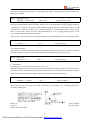
Ramp-up time means the time needed for the inverter to increase the frequency from 0Hz to the maximum
operating frequency (See t1 in the diagram). Ramp-down Time means the time needed for the inverter to
decrease the frequency from the maximum operating frequency to 0Hz (See t2 in the diagram).
F
Max Oper. F.
t2
t1
Note:
The versions previous to Vr2.0 took 50Hz as the base of ramp time.
HLP-A Series inverter have altogether 4 Ramp Times. For Ramp Time 2.3.4 the user can select the different
ramp up or down time through the external terminals or switching of ramp time according to the actual needs.
In the internal control multi-speed operation, different ramp time can be selected through easy PLC.
34
PDF wurde mit pdfFactory Pro-Prüfversion erstellt. www.context-gmbh.de
Inverters
Generally the default of the inverter is Ramp Time 1, which is factory set depending on the model. Ramp
Time 4 is for the jogging ramp time. For the factory setting of parameters refer to the table in CD006.
The related parameters: CD050~CD055 and CD078.
CD020~CD030
Factory Reserved
CD031 Starting Mode
Set Range:0—1
Unit:1
Factory Setting:0
Two starting modes are available for the needs of different equipment.
0:Start from the starting frequency.
When CD141 is set to 0, i.e. DC braking is invalid at start, it starts running from the starting frequency. When
CD141 is set to any non-zero value, i.e. DC braking is valid at start, itl first performs a DC braking at start,
and then starts from the starting frequency.
For the related parameters refer to CD040, CD140 and CD141.
1:Start by frequency track
This setting can be used for the restarting of large inertia load. When restarting, the inverter will trace the
former frequency from the set frequency downward. In case of large inertia equipment, when restarting, it
can implement the running command and track the former frequency right away without waiting for the
complete stop of the equipment to save time.
Note: When the inverter is restarted by frequency track, it will start tracking the frequency from its set
frequency downward, and search it at the highest speed. When restarting, the current becomes higher, and
over-current or stall may occur. So attention must be paid to the adjustment of current level of frequency
track. Generally, CD144 is adjusted around 100. The concrete value can be set according to the
characteristics of mechanical load.
Run comm..
Set F.
Ouput F.
Output Power
CD032 Stopping Mode
Set Range:0—1
Unit:1
Factory Setting:0
Two stopping modes are available for the needs of different equipment.
0:Decelerating Stop
When CD142 is set to 0, DC braking is invalid. When DC braking is invalid, the inverter will decelerate to
the stopping frequency, and then stop outputs, and the motor will coast to stop. When CD142 is set to any
non-zero value, DC braking is valid, and the inverter will first decelerate to the stopping frequency, and then
stop by DC braking.
DC braking at stop is usually used for high position stop or for positioning control. It must be noticed that
frequent uses of DC braking will cause over-heat of the motor.
35
PDF wurde mit pdfFactory Pro-Prüfversion erstellt. www.context-gmbh.de
Inverters
For the related parameters refer to CD042, CD140 and CD142.
1:Coasting Stop
When the inverter receives a STOP command, it will immediately stop output and the motor will coast to
stop. When the coasting stop mode is selected, DC braking is invalid.
CD033 Source of Operation Commands
Set Range:0—2
Unit:1
Factory Setting:0
0: Set by the Operator
Operation commands are given via the digital operator.
1: Set by external terminals.
Operation commands are given via external terminals, i.e. multi-input terminals
2: Set by communication ports.
Operation commands are given via communication ports.
CD034 Source of Operating Frequency
Set Range:0—2
Unit:1
Factory Setting:0
0: Set by the operator. Operating frequency is given via the digital operator.
1 : Set by external terminals. Operating frequency is controlled by analog signals input via external
terminals. The signal type is determined by CD065. For the related parameters refer to CD065-CD070.
2: Set by communication ports. Operating frequency is given via the serial communication.
(Note: 0—15 corresponds to 0—20K Hz)
CD035 Carrier Frequency
Set Range:0—15
Unit:1
Factory Setting:5
The carrier frequency has some relation with the electromagnetic noise of the motor, and meanwhile the
level of the carrier frequency has certain relation with the heating capacity of the inverter and the
interference to the environment. See the following table:
Carrier
Electromagnetic
Heating Capacity
Interference to
Frequency
Noise
Low
High
Small
Little
High
Low
Large
Great
the Environment
Carrier Frequency Corresponding Table
Set Value
0
1
2
3
4
5
6
7
8
9
10
11
12
13
14
15
2
3
4
5
7
8
9
10
11
13
15
17
20
Carrier
Frequency
0.7
1 1.5
KHz
As shown in the table above, the higher the carrier is, the lower the electromagnetic noise of the motor will
be, but the stronger its interference to other systems will be and the greater the heating capacity of the
inverter will have. Under higher ambient temperature and heavier load of the motor the carrier frequency
should be decreased properly to improve the heat characteristics of the inverter.
36
PDF wurde mit pdfFactory Pro-Prüfversion erstellt. www.context-gmbh.de
Inverters
The factory setting of carrier frequency is depending on the model. For specific data refer to the table in the
description of CD006.
CD036 Jogging Frequency
Set Range:0.00—400.00
**
Unit:0.01
Factory Setting:5.00
The parameter set can realize the jogging function when the inverter is tested. The jogging operation can be
only achieved through the external terminals, which can be set by multi-input terminals. Jogging frequency
is limited by the frequency upper/lower limits. While the jogging function is implemented, other running
commands are invalid. The ramp-up time of jogging frequency is set by Ramp-up Time 4. When the jog
button is released the inverter will stop output immediately. In case of jogging function please set the
corresponding multi-input terminals to 07 or 08.
This function is only valid at stop. It is invalid at running. For the related parameters refer to CD050-CD055.
CD037 Rev Rotation Select
Set Range:0—1
Unit:1
Factory Setting:1
0: Rev Rotation disable
1: Rev Rotation Enable
This function is suitable for the motor, which is not allowed to rotate reversely, to prevent workers from false
operation. When the reverse rotation is disabled, the motor can only rotate forward, not reverse.
CD038 STOP key
Set Range:0—1
Unit:1
Factory Setting:1
0:STOP invalid.
1:STOP valid.
This parameter set is only valid when CD033 is set to l or 2.
When the control mode is set for external terminals or communication control, STOP key on the panel can be
chosen to be valid or invalid. When choosing it as valid, STOP key can stop the inverter in running. When it
needs to restart, the former running signal must be released before restarting the inverter.
CD039 S-Curve Time
Set Range:0—6500S
Unit:1
Factory Setting:1
This parameter can be set for no impact slow start or slow stop of the inverter when starting or stopping.
When starting S-curve the inverter will make accelerating or decelerating curve of different speed rates
according to Ramp Time.
When CD039 is set as 0, S-curve is invalid, i.e. it will accelerate or decelerate in linear. Without
consideration of stall the actual accel/decal time = (CD012+CD039)/2. The parameter is only valid when
CD012 is less than CD039.
37
PDF wurde mit pdfFactory Pro-Prüfversion erstellt. www.context-gmbh.de
Inverters
CD040 Up/down
Frequency Step Length: 0.01~2.5
Factory Setting:0.01
This parameter can be set in combination with CD073 for Up/Down of external control and the speed of
increase and decrease.
In case of CD073=1 the step length of Up/Down=the set value of CD040, i.e., the range can be set to
0.01~25HZ.
In case of CD073=0 the step length of Up/Down=the set value of CD040 ×10, i.e., the range can be set to
0.1~25.0HZ.
CD041 Starting Frequency
Set Range:0.1—10.0 Hz
Unit:0.1Hz
Factory Setting:0.5
Starting frequency is the initial frequency when the inverter is started. If the starting frequency is set to
4.0Hz, the inverter will run between 4.0 Hz and the maximum operating frequency after its start at 4.0Hz .
The actual maximum operating frequency is limited by the upper limit of frequency.
For the related parameters refer to CD031, CD140 and CD141.
CD042 Stopping Frequency
Set Range:0.1—10.0 Hz
Unit:0.1Hz
Factory Setting:0.5
When stopping the inverter will decrease its frequency to the stopping frequency and then stop running or
start DC braking to stop.
If CD142 is set to 0, DC braking is invalid at stop and the inverter will stop running.
If CD142 is set for valid, the inverter will stop by DC braking.
For the related parameters refer to CD032, CD140 and CD142.
CD043 Auto Torque Compensation
Set Range:0.1—10.0 %
Unit:0.1%
Factory Setting:2.0%
This parameter can be set for the auto output of
V
extra voltage when the inverter is running to
achieve higher torque, which can compensate
100%
for the under-torque at lower frequency. The
torque compensation should not be too big and
it should be set slowly from low to high
according to the actual situation.
F
Torgue Compens.
Insufficient compensation will result in the
under-torque of the motor at lower frequency. And over compensation will lead to too bigger torque, which
will produce a shock to the machine and even result in a trip of the inverter under serious situation.
CD044 Skip Frequency 1
CD045 Skip Frequency 2
**
38
PDF wurde mit pdfFactory Pro-Prüfversion erstellt. www.context-gmbh.de
Inverters
CD046 Skip Frequency 3
Set Range:0.00—400.00 Hz
Unit:0.01Hz
Factory Setting:0.0
CD047 Skip Frequency Range
Set Range:0.10—2.00 Hz
**
Unit:0.01Hz
Factory Setting:0.5
F
CD046
CD045
CD047
CD044
CD047
These three frequency skipping points are set for avoiding a mechanical resonance point. In case of
CD047=0, all skip frequencies are invalid. The actual skip frequency range is two times that of CD047, as
shown in the above diagram.
CD048 Timer 1 Time
Set Range:0~10.00
CD049 Timer 2 Time
Unit: 1
Factory Setting:0.01
Unit: 1
Factory Setting:0
Set Range:0~100
Timer 1 is a timer of 0.1s ~ 10.0s and Timer 2 is a timer of 1s ~ 100s. When the timer start at multi-inputs is
closed (on) the timer starts to count time. When it reaches the set time the corresponding multi-output contact
will act. When the timer start is opened (off) the timer time at the multi-output will be reset.
(At Input) Timer start
ON
ON
(At Output) Timer
CD048
For example, set CD048=5.0s. When the external control terminal (Multi-Input) is valid the output terminal
will be valid after five (5.0) seconds, the signal of which can be used to control other corresponding signals.
CD050
Multi-input 1(FOR function)
Factory Setting: 02
CD051
Multi-input 2(REV function)
Factory Setting: 03
CD052
CD053
Multi-input 3(RST function)
Multi-input 4(SPH function)
Factory Setting: 10
Factory Setting: 17
CD054
Multi-input 5(SPM function)
Factory Setting: 18
39
PDF wurde mit pdfFactory Pro-Prüfversion erstellt. www.context-gmbh.de
Inverters
CD055
Multi-input 6(SPL function)
Set Range:00—32
Factory Setting: 19
Unit:No
00: Invalid.
The terminal is set for empty to prevent false actions.
01: RUN
Running. It can be combined with other terminals to compose multiple control
modes.
02: FOR
Forward Rotation
03: REV
Reverse Rotation
04: STOP
Stopping
05: FOR/REV
Switching of FOR/REV rotation
06: JOG
Jogging
07: Jog FOR Rotation
08: Jog REV Rotation
09: Emergent Stop:
10: RST
Emergent stop. It can receive external emergent stop command or other fault signals
Reset. This terminal can be used for reset after a fault is removed.
11: Reserved
12: Over-heat of heat sink or motor: This contact can be used to detect over-heat of the heat sink or motor
to protect the motor and inverter.
13: External Control Timer 1 Start: When the contact is closed, the timer will start and begin to count time.
When the timer reaches the set point the corresponding multi-inputs will act.
14: External Control Timer 2 Start
15~16:Reserved
17: High speed
18: Middle speed
High, middle and low speed can compose three kinds of operation mode
with different frequencies. In the three terminals the high-end signal has
19: Low speed
priority. Low, Middle and High Speed are determined respectively by Frequency 2,
20: Multi-speed 1
3, 4.
7-speed setting can be composed through Multi-speed 1, 2, 3.
21: Multi-speed 2
22: Multi-speed 3
23: Ramp Time 1: This terminal can be used to select the ramp time of the inverter.
24: Ramp Time 2: 4 kinds of ramp time are available for choice.
25: UP Function
When the switch of this terminal acts the frequency setting of the inverter will be
increased or decreased by one unit. When the switch of the terminal is hold the
frequency will increase or decrease rapidly to a point and then increase or decrease
26: Down Function
at even speed. When the power is up again after the power breakdown the changed
frequency will not be memorized.
27: Counter Pulse
When this terminal is set for the counter it can receive the pulse signal of ≤250HZ
28: Counter Reset
and counts.
When this contact acts it will clear the present counting values displayed, restore
C00 and restart counting.
﹡29:Drawing Start
When this contact is triggered the drawing action starts.
﹡ 31 : AutoPLC Reset Suspend
This contact can be used to achieve the function of AutoPLC clear
suspend.
﹡32: PID Valid
When this contact is closed, PID function starts. PID Function start is only valid
40
PDF wurde mit pdfFactory Pro-Prüfversion erstellt. www.context-gmbh.de
Inverters
during operation.
Note:
① The above functions with the mark of ﹡ are dedicated to the inverter of A series, which may be
not available for P or J series.
② The functions of above 17 – 22 and 31 are not available for P series, and the function of above 32 is
not available for J series.
Explanation:
1. Three multi-function terminals can be used for the connection method of three-wire system for the
realization of switching of FOR/REV rotation, which is extensively applied in the cases of FOR/REV
switching of photoelectric switches.
① Select FOR, REV and RST.
② Parameter setting:
STOP RUN
CD033=1 for external control
FOR
REV
RST
DCM
CD051=03 for REV Rotation
CD050=02 for FOR rotation
CD052=04 for Stop
③ Action Description:
When triggering FOR, the inverter will rotate forward (start);
When triggering REV, the inverter will rotate reverse;
When pressing STOP, the inverter will stop.
2. RUN, DCM, F/R can be used for Start, Stop and switching of FOR/REV:
① Select FOR and REV
STOP RUN
② Parameter setting:
FOR
REV
RST
DCM
CD033=1 for external control
CD050=01 for RUN function
CD051=05 for switching of F/R
When K2 is opened it rotates forward, while K2 is closed it
rotates reverse.
3. Description of Ramp Time 1 and 2:
1) This function is only valid when CD076 is set to 0, 1 and 2. Under the disturbance and internal control
multi-speed it is invalid.
2)
3)
Any two multi-inputs can be combined for 4 kinds of ramp time for selection.
The related multi-inputs are set for Ramp Time 1, 2. Take the terminals of SPH and SPM as example,
when SPH CD053 is set to 23 and SPM CD054 is set to 24, SPH and SPM are now Ramp Time 1, 2.
SPH
SPM
Result
OFF
OFF
Ramp Time 1
41
PDF wurde mit pdfFactory Pro-Prüfversion erstellt. www.context-gmbh.de
Inverters
ON
OFF
Ramp Time 2
OFF
ON
Ramp Time 3
ON
ON
Ramp Time 4
4. Function description of High, Middle and low speed terminals:
F
H. speed
M.speed
L. speed
Main frequency
T
Run command
L. speed
M.speed
L. speed
RUN
SPL
SPM
SPH
ON
OFF
OFF
OFF
ON
ON
OFF
OFF
ON
ON/OFF
ON
OFF
ON
ON/OFF
ON/OFF
ON
Result
Main speed, the frequency runs at
the set value of CD000.
Low speed, the frequency runs at
the set value of CD080.
Middle speed, the frequency runs
at the set value of CD081.
High speed, the frequency runs at
the set value of CD082.
Note:
(1)This function is only valid when CD076 is set to 1, i.e. for 4-Speed of external control.
(2)Low, middle and high speed frequency are determined by Frequency 2,3, 4.
(3)Ramp time is determined by Ramp Select terminal.
(4)When all high, middle and low speeds have signal inputs it will give priority in the sequence of high,
middle and low speed.
5. Description of UP and DOWN Function:
42
PDF wurde mit pdfFactory Pro-Prüfversion erstellt. www.context-gmbh.de
Inverters
Max.operating Frequency
Set frequency
F.Lower Limit
Up Command
Down Command
UP
DOWN
Result
ON
OFF
Frequency increase
OFF
ON
Frequency decrease
ON
ON
Not increase or decrease
Note:
(1)The function of UP and DOWN is only valid when the operator is selected for the source of the operating
frequency, i.e. CD034=0.
(2)When the UP terminal is closed the frequency of the inverter will increase.
(3)When the DOWN terminal is closed the frequency of the inverter will decrease.
(4)When both UP and DOWN terminals are closed at the same time the frequency will neither increase nor
decrease. It is regarded as invalid.
(5)When the frequency reaches the max operating frequency it will stop increasing.
(6)When the frequency reaches the min frequency or its lower limit, it will stop decreasing.
(7)After a power breakdown the set value of CD000 will be memorized instead of the frequency.
(8)When using the function of UP and DOWN, the keys of △▽ of the panel are valid. After changing the
values it needs to press SET (ENTER) key for confirmation and then the inverter can implement the
action. Meanwhile the value will write to CD000, which will be memorized after a power breakdown.
(9)When keeping pressing UP or DOWN,the frequency will increase or decrease rapidly to a point and then
increase or decrease at even speed.
(10)The value changed by UP or DOWN can be set through CD072 for confirmation of whether it should be
memorized or not memorized. For details refer to CD072.
6.
Function Description of Multi-speed 1, 2 and 3:
They are only valid when CD076 is set to 2. For details refer to CD076.
7.
Function Description of Counter:
C00
C00
…cn
t1
t2
43
PDF wurde mit pdfFactory Pro-Prüfversion erstellt. www.context-gmbh.de
Inverters
Counting Value reach
Counting Value reset
Note:
(1)The signal width triggered should not be lower than 2 msec(t1、t2≥2msec).
(2)When the counting value is reached the corresponding multi-output contact will act.
(3)This counter can only count again after reset.
(4)When reaching to 65535 the counter will not count again.
8. Description of AutoPLC Clear Suspend:
For details refer to 10. Example Application of AutoPLC Suspend in Appendix 1 and the description of
related parameters in CD095.
﹡CD056
Multi-Output 1(DRV function)
Factory Setting:01**
﹡CD057
Multi-Output 2(UPF function)
Factory Setting:05
﹡CD058
Multi-Output 3(FA, FB, FC function)
Factory Setting:02
﹡CD059
Multi-Output 4(KA, KB function)
Set Range:00—32
Unit:1
Factory Setting:00
00: Invalid: The terminal is set for no function to prevent false actions.
01: In Run: The contact will act when the inverter has output or receives the running command.
02: Fault Indication: The contact will act when the inverter detects abnormal conditions.
03 : Zero Speed: The contact will act when the output frequency of the inverter is less than its starting
frequency.
04: DC Braking indication: The contact will act when the inverter is in DC braking.
05: Set Frequency reach: The contact will act when the output frequency of the inverter reaches the set
frequency.
06: Uniform Frequency 1 Reach: The contact will act when the output frequency of the inverter reaches the
designated frequency (CD061).
07:。Uniform Frequency 2 reach: The contact will act when the output frequency of the inverter reaches the
designated frequency (CD062).
08: In Accel: The contact will act when the inverter is in ramp-up.
09: In Decel: The contact will act when the inverter is in ramp-down.
10: Inverter Over-load Alarm: The contact will act when the inverter detects over-load.
11: Motor Overload Alarm: The contact will act when the inverter detects over-load of the motor.
12: In Over-torque Detect: The contact will act when the inverter detects over-torque.
13: Low Voltage Alarm: The contact will act when the inverter detects low voltage.
﹡14: Single Step End: The contact will act and generate one pulse when the inverter finishes a single step
in implementation of program operation.
﹡15: Process End: The contact will act and generate one pulse when the inverter finishes all the steps (i.e.
after one cycle) in implementation of program operation.
16:Set Counter Reach:
The contact will act when the inverter implements the external counter and the
counting value is equal to the set value (CD064).
17:Middle Counter Reach: The contact will act when the inverter implements the external counter and the
44
PDF wurde mit pdfFactory Pro-Prüfversion erstellt. www.context-gmbh.de
Inverters
counting value is greater than or equal to the set value (CD075).
18:External Control Timer 1 reach: The contact will act when the timer reaches the set value.
19:External Control Timer 2 reach:
20:4∽20mA disconnected: When AI input signal is opened the contact will act.
﹡25:Auxiliary Pump 1:
This contact controls the starting and stopping of auxiliary pumps. For details
refer to Operation of Multi-pumps.
﹡26:Auxiliary Pump 2
﹡ 27 : Drawing reach:
The contact will act when the drawing action is finished. The contact will
automatically reset when the inverter stops.
﹡28:PID Lower Limit Alarm: This contact will act when the PID feedback is smaller than the lower limit
(the set value of CD156).
﹡29:PID Upper Limit Alarm: This contact will act when the PID feedback is greater than the upper limit
(the set value of CD155).
30:Fan act: When the temperature of the inverter is increased or it is in running, this contact will act.
31:Electromagnetic Relay Act: When the contact pulls in, the corresponding multi-function terminal will
act.
32:Braking Resistor Act: When the inverter is in running and the DC voltage reaches the braking voltage
the contact will act.
Note:
① The above functions with the mark of ﹡ are dedicated to the inverter of A series, which may be
not available for P or J series.
② The functions of above 14, 15 and 27 are not available for P series, and the functions of above 25,
26, 28 and 29 are not available for J series.
CD060
Multi-Output AM
Set Range:0—7
**
Unit:1
Factory Setting:0
Functions: Output terminal of digital frequency, generating pulse or 0 —10V analog. In combination with
CD071 it can be connected with a corresponding instrument with the measuring range below 10 to be used
for external monitoring.
0 : 0 ~ 10V analog output, corresponding to output frequency. 0 ~ 10V corresponds to 0 ~ Maximum
operating frequency
1:0~10V analog output, corresponding to output current. 0~10V corresponds to 0~two times of the rated
current of the inverter.
2:Analog output, corresponding to DC bus voltage. 0~10V corresponds to 0~1000V.
3:Analog output, corresponding to AC output voltage. 0~10V corresponds to 0~510V/255V.
(Note: The machine type of three phase, 380V corresponds to 510V and the machine type of single
phase, 220V corresponds to 255V)
4:Pulse Output, corresponding to operating frequency: 1 Pulse/Hz,(50% of capacity ratio)
5:Pulse Output, corresponding to operating frequency: 2 Pulse /Hz,(50% of capacity ratio)
6:Pulse Output, corresponding to operating frequency: 3 Pulse /Hz,(50% of capacity ratio)
7:Pulse Output, corresponding to operating frequency: 6 Pulse /Hz,(50% of capacity ratio)
CD061
Uniform Frequency 1
**
45
PDF wurde mit pdfFactory Pro-Prüfversion erstellt. www.context-gmbh.de
Inverters
CD062
Uniform Frequency 2
Set Range:0.00—400.00 Hz
CD063
Unit:0.01 Hz
Factory Setting:0.00
Uniform Frequency Range
Set Range:0.00—10.00 Hz
**
Unit:0.01 Hz
Factory Setting:0.50
When the output frequency is more than the uniform frequency the corresponding multi-outputs will act. The
uniform frequency range acts as a hysteresis loop.
When the inverter is in the operation of multi-pumps, CD061 (Uniform Frequency 1) is used as high speed
frequency and CD062 is set as low speed operating frequency. The definitions of the corresponding multifunction contacts are changed.
t
T
Uniform
Uniform
Frequency
Frequency Range
When output F. is higher
than uniform F, the corresp.
multioutputs act.The
t
t
uniform F. range is uaed as
hysteresis LOOP.
Uniform Fequency
Multi-Output
t
CD064
Counting Value
**
Set Range:0—65500
Unit:1
Factory Setting:0
An external terminal of multi-function can be used as a trigger for the counter. When the counter reaches the
set value of CD064 the corresponding multi-output contact will act. After the counter is cleared and reset it
will start counting again. A proximity switch or optoelectronic switch can be used for the triggering signals.
CD065
Analog Input
Set Range:0—10
Unit:1
Factory Setting:0
0:0~10V
1:0~5V
2:0~20mA
3:4~20mA
4:0-10V 与 4-20mA stacked
5:XIA
6:(VI+XIA)/2
7:(3VA+XIA)/4
8:(XIA+XIB)/2
9:Max (XIA, XIB)
10:Min (XIA,XIB)
This parameter can be set for different analog input signals.
When CD065=4, the output frequency =1/2(U/Umax + I/Imax)× 50Hz
Among which: U:Analog Voltage; Umax: Maximum Analog Voltage;
I: Analog Current; Imax: Maximum Analog Current.
For example, When +10V and 20mA are respectively entered for the analog input, the output frequency of
the inverter is 50Hz.
CD066
Lower Analog Frequency
46
PDF wurde mit pdfFactory Pro-Prüfversion erstellt. www.context-gmbh.de
Inverters
Set Range:0.00—400.00 Hz
CD067
Unit:0.01 Hz
Factory Setting:0.00
Bias Direction at Lower Frequency
Set Range:0—1
Unit:1
Factory Setting:0
0:Positive direction
1:Negative direction
Bias direction means the instruction of FOR/REV rotation command. Positive bias indicates forward
rotation while negative bias indicates reverse rotation. For details refer to the diagram in CD070.
CD068
Higher Analog Frequency
Set Range:0.00—400.00 Hz
CD069
Unit:0.01Hz
Factory Setting:50.00
Bias Direction at Higher Frequency
Set Range:0—1
Unit:1
Factory Setting:0
0:Positive direction
1:Negative direction
Bias direction means the instruction of FOR/REV rotation command. Positive bias indicates forward
rotation while negative bias indicates reverse rotation. For details refer to the diagram in CD070.
CD070
Analog Negative Bias Reverse
Set Range:0—1
Unit:1
Factory Setting:0
0:Negative bias Rev is not allowable.
1:Negative bias Rev is allowable.
The parameter group is set for the measuring range and zero point of the external analog terminals and can be
combined for any kind of curve to control the operation of the motor.
Rev. Area
0
4mA
50 Hz
5V
12mA
For. Area
10V
20mA
F
50
0
4mA
10V
20mA
F
40
Setting:CD066=50 CD067=1 CD068=50
CD069=0 CD070=1
Note: this curve can be easily used in complicated
applications in combination with other curves. When using it
the instruction of FOR/REV run from external terminals is
still valid. When switching, the curve will turn reverse.
Setting:CD066=50 CD067=0 CD068=0
CD069=0 CD070=0
Note: this curve is a kind of special application of reverse ramp
setting. When using transmitter for the control of pressure,
temperature and others and while the control has higher
pressure and output signals but requiring the corresponding
commands of stop or deceleration on the inverter this curve can
satisfy the demand properly.
Setting:CD066=10 CD067=1 CD068=40
CD069=0 CD070=1
Note: this method is used extensively. The user can use it
flexibly.
47
PDF wurde mit pdfFactory Pro-Prüfversion erstellt. www.context-gmbh.de
Inverters
0V
4
2V 10V
20mA
10
40
F
0V
4mA
10
CD071
2V
4.8mA
10V
20mA
AM Analog Output Gain
Set Range:0.0—100.0%
Setting:CD066=10 CD067=1 CD068=40
CD069=0 CD070=1
Note; this curve is the extension of the above curve.
2V~10V(4.8mA~20mA)corresponds to 0Hz~40HZ; the signal
of 0V~2V(4~4.8mA)is invalid. It can be used to avoid noice
disturbance. In harsh environment it is better not to use signals
below 1V for setting the operating frequency of the inverter.
Unit:0.1%
Factory Setting:100.0
This parameter can be used to adjust the output voltage value of Multi-output 6 to adapt to frequency meters
with different measuring range and also used to correct a frequency meter. For example, for an externally
connected frequency meter with the measuring range of 0~5V, a multi-function terminal can be used to
display its operating frequency. Then it can be corrected with this parameter. It can be achieved by setting
CD071=50 .
CD072
UP/DOWN Function
Set Range:0-1
Unit:1
Factory Setting:0
0:Not memorized
1:Memorized
This parameter can be set for the selection of whether the values changed by the UP or DOWN shall be
memorized or not after stop. The changed values whether to be memorized or not means when they are
changed by UP or DOWN during operation and the inverter is restarted after stop these changed values shall
be memorized or not after restart. When CD072 is set to 0, the changed value will not be memorized and
when it is set to 1, the changed values will be memorized. The set values of CD000 will be memorized after
restart.
For the related parameters refer to CD050-CD055.
CD073
UP/DOWN Speed
Set Range:0-1
Unit:1
Factory Setting:0
0:0.01Hz. Minimum UP/DOWN speed is 0.01Hz.
1:0.1Hz. Minimum UP/DOWN speed is 0.1Hz.
Through the changes of this set value the UP/DOWN speed unit can be adjusted to meet the needs of
different customers.
CD074
Analog Filtering Constant
48
PDF wurde mit pdfFactory Pro-Prüfversion erstellt. www.context-gmbh.de
Inverters
Set Range:0-50
Unit:1
Factory Setting:20
The setting of this parameter is related to the analog responding speed. The higher the value of CD074 is set,
the lower the analog responding speed will be.
CD075
Intermediate Counter
Set Range:0-65500
Unit:1
Factory Setting:0
Unit:1
Factory Setting:0
Refer to CD064.
CD076
PLC Operation
Set Range:0—5
* This function is not available for the inverter of P series. Default is normal operation.
0:Normal operation, i.e. the inverter is running in the normal control mode.
1 : External control 4-Speeds (Refer to the function description and diagram of three terminals of high,
middle and low speed in C050~C055)
2:External control multi-speeds
F
Main F
T
FOR
Multispeed1
Multispeed2
Multispeed3
Multi-function Terminals
Results
Multi-speed 1
Multi-speed 2
Multi-speed 3
OFF
OFF
OFF
ON
OFF
OFF
OFF
ON
OFF
ON
ON
OFF
OFF
OFF
ON
ON
OFF
ON
Main frequency and frequencies are determined
by CD000 or potentiometer.
Multi-speed 1 and frequency are determined by
CD080.
Multi-speed 2 and frequency are determined by
CD081.
Multi-speed 3 and frequency are determined by
CD082.
Multi-speed 4 and frequency are determined by
CD083.
Multi-speed 5 and frequency are determined by
CD084.
49
PDF wurde mit pdfFactory Pro-Prüfversion erstellt. www.context-gmbh.de
Inverters
OFF
ON
ON
ON
ON
ON
Multi-speed 6 and frequency are determined by
CD085.
Multi-speed 7 and frequency are determined by
CD086.
Note:
① It is only valid to realize the external control 8-Speeds operation when Multi-inputs are set for Multispeed 1, 2, 3 and CD076 is set to 2.
② Multi-speed 1, 2, 3 can be used to make up 7-Speeds and 8-Speeds adding the main frequency .
③ The frequencies of Speed Step 1 ~ Step 7 are determined by CD080~CD086.
④ Each ramp time is determined by the external multi-function terminal.
⑤ The directions of each program operation are determined by the external multi-function terminals.
⑥ The main frequency can be set in two ways. One method is to set it through CD000 and another is to set it
through the potentiometer. When CD034 is set to 1 the frequency of Main Frequency is set by the
potentiometer. For the related parameters refer to CD000, CD034 and CD080~CD086.
3:Disturbance (Traverse function)
This is a special parameter in the chemical fiber and printing and dying industries to realize the traverse
function. Except the commands of stop, external faults and emergency stop all other commands are not
accepted at running.
F
CD000
CD086
CD087
CD088
CD086
CD080
Note:
① The frequency at each inflection point is determined by CD000 and CD080.
② Skip Frequency is determined by CD086.
③ Running Time is determined by Timer CD087 and CD088.
④ The related parameters: CD000, CD080~CD088.
4:Internal control Multi-speeds
50
PDF wurde mit pdfFactory Pro-Prüfversion erstellt. www.context-gmbh.de
Inverters
CD087 CD088
CD089 CD090
CD091 CD092 CD093 CD094
T
Note:
① Main speed and 7-speeds composes 8-speeds.
② The ramp time of each speed step is set by PLC Ramp Time CD079. Refer to the detail descriptions of
CD079.
③ Running Time is set by Timer CD087~CD094. For the control steps not to be used the timer can be set to
0.
④ Running direction of each speed step is determined by CD078.
⑤ In the internal control multi-speed operation the running time and direction are determined by the setting
of internal parameters. Any switching of external time and FOR/REV rotation is invalid.
5:Drawing
This is a special parameter for the constant speed of unwinding and rewinding. By using this function the
linear speed constant in certain accuracy can be realized.
F
CD080
CD081
CD000
T
Multi-input
Multi-output
Note:
① Through triggering of the external multi-function terminal the drawing action begins.
② In implementation of the drawing action the actual running time is T=CD087×10.
③ when the drawing action is finished the inverter will run at the constant seed of CD081 and the
corresponding multi-output contact will act at the same time. Until receiving the STOP command the
inverter will stop running and the multi-output contact will reset.
CD077 Auto PLC
Set Range:0—3
Unit:1
Factory Setting:0
* This function is not available for the inverter of P series.
0:Stop after the program runs one cycle.
1:Cycling running.
2:Stop after it runs one cycle automatically(STOP for intervention).
3:Auto running and cycling (STOP for intervention)
This parameter setting is only valid when CD076 is set to 4. For relevant parameters refer to CD000, CD076
and CD078~CD094.
51
PDF wurde mit pdfFactory Pro-Prüfversion erstellt. www.context-gmbh.de
Inverters
Explanation:
1. Stop after the program runs one cycle.
When the command of auto program operation is given, the inverter will run with each set value of
internal parameters. It will run for one cycle and then stop automatically. The inverter will not restart and
run until it receives another command of operation.
2. Cycling run.
When the command of operation is given, the inverter will run in sequence with the frequency of every
speed step and running time set by each of the internal parameters and will recycle. During the cycling
run, except the commands of stop, external faults and emergency stop, all other commands will not be
accepted.
3. Stop after it runs one cycle automatically(STOP for intervention)
STOP RUN
FOR
REV
RST
DCM
Note:
① When the command of auto program operation is given the inverter will run with each parameters. But it
will stop first and then restart at changing of each step and will stop automatically after running for one cycle.
The inverter will not restart and run until it receives another command of operation.
② The frequencies of each speed step are set by CD000 and CD080~CD086.
③ The running times of each speed step are set by CD087~CD094.
④ The running direction is set by CD078.
CD078 PLC Running Direction
Set Range:0—255
Unit:1
Factory Setting:0
This parameter is only valid when CD076 is set to 4. This parameter setting determine the running direction
of each frequency of CD080~CD086 and CD000 in the program operation. The setting method is as follows:
The rotation direction is set first in the binary 8 bits mode, and then converted to a decimal value for the
setting of this parameter. For instance:
Bit0—7
7
6
5
4
3
2
1
0
0
1
0
0
1
0
1
0
0:For.
1:Rev.
Main Speed(CD000)
Frequency 1(CD080)
For.
Rev.
52
PDF wurde mit pdfFactory Pro-Prüfversion erstellt. www.context-gmbh.de
Inverters
Frequency 2(CD081)
Frequency 3(CD082)
Frequency 4(CD083)
Frequency 5(CD084)
Frequency 6(CD085)
Frequency 7(CD086)
For.
Rev.
For.
For.
Rev.
For.
The parameter value 01001010 is converted to a decimal value:
1×26+1×23+1×21=64+8+2=74
Then CD078=74
CD079 PLC Ramp Time
Set Range:0~65535
Unit:1S
Factory Setting:0
This parameter is only valid when CD076 is set to 4.
This parameter is set to determine the ramp time values for Step 1~4 of the internal control multi-speed. The
setting method is as follows:
① Determine each Ramp Time in the binary 2 bit mode
Bit1
Bit0
Ramp Time
0
0
Ramp Time 1 CD012, CD013
0
1
Ramp Time 2 CD014, CD015
1
0
Ramp Time 3 CD016, CD017
1
1
Ramp Time 4 CD018, CD019
② Determine the Ramp time of each speed step in the binary 16 bit mode
Step 8
Step 7
Step 6
Step 5
Step 4
Step 3
Step 2
Step 1
t8
t7
t6
t5
t4
t3
t2
t1
0
0
0
0
0
0
0
0
0
1
1
0
0
0
t1 Select Ramp Time 4
t2 Select Ramp Time 1
t3 Select Ramp Time 3
The setting value:
t4 Select Ramp Time 2
t5 Select Ramp Time 1
1×20+1×21+1×25+1×26=99
So CD079 is set to 99
t6 Select Ramp Time 1
Attach:20=1
t7 Select Ramp Time 1
t8 Select Ramp Time 1
24=16
21=2
22=4
23=8
25=32 26=64 27=128
CD080
CD081
Frequency 2
Frequency 3
Factory Setting
Factory Setting
15**
20
CD082
Frequency 4
Factory Setting
25
CD083
CD084
Frequency 5
Frequency 6
Factory Setting
Factory Setting
30
35
CD085
Frequency 7
Factory Setting
40
53
PDF wurde mit pdfFactory Pro-Prüfversion erstellt. www.context-gmbh.de
1
1
Inverters
CD086
Frequency 8
Factory Setting
Set Range:0.00—400.00 Hz
0.5
Unit:0.01 Hz
This parameter is set in combination of the multi-inputls to select 4-speeds of external control, multi-speeds
of external control or multi-speeds of internal control. For the relevant parameters refer to the description of
CD076 and CD087~CD094.
CD087
Timer 1
Factory Setting
10.0**
CD088
Timer 2
Factory Setting
10.0
CD089
Timer 3
Factory Setting
0.0
CD090
Timer 4
Factory Setting
0.0
CD091
Timer 5
Factory Setting
0.0
CD092
Timer 6
Factory Setting
0.0
CD093
Timer 7
Factory Setting
0.0
CD094
Timer 8
Factory Setting
0.0
Set Range:0.0—6500.0S
Unit:0.1S
This parameter is set for the internal control multi-speeds and the running time of drawing function. For the
relevant parameter refer to CD076 and CD080~CD088.
CD095
AutoPLC Memory Function
Set Range:0—1
Factory Setting:0
0:Not memorized
1:Memorized
This parameter is set to determine whether the inverter is to realize the suspending function in AutoPLC
mode. In case of CD095=1 it can memorize the status in which the inverter is running and will memorize it at
stop or fail. It will continue to run when returning to normal. In case of CD095=0 it will not memorize. For
specific applications refer to Example Application 10 in Appendix 1.
CD096~D109
*CD110
Reserved
Number of Auxiliary Pump
Set Range:0—2
Unit:1
Factory Setting:0
* This function is not available for the inverter of J series.
This parameter is set for the number of auxiliary pump. The start or stop of the auxiliary pumps is controlled
by using the multi-output contacts and Auxiliary Pump 1 or Auxiliary Pump 2 is controlled through the
peripheral control circuit.
*CD111
Continuous Running Time of Auxiliary Pumps
Set Range:1—9000(min)
Unit:1
Factory Setting:60
* This function is not available for the inverter of J series.
In case of two pumps with only one pump in duty, in order to ensure each pump to work evenly, it will be
switched to another pump when its running time reaches the set value of CD111.
54
PDF wurde mit pdfFactory Pro-Prüfversion erstellt. www.context-gmbh.de
Inverters
*CD112
Interlocking Time of Auxiliary Pump
Set Range:1—250S
Unit:1
Factory Setting:5S
* This function is not available for the inverter of J series.
This parameter is set to determine the interlocking time of two auxiliary pumps when switching with each
other.
CD111
Aux. pump
1
Aux. pump
2
OFF
ON
ON
OFF
CD112
*CD113
High Speed Running Time
Set Range:1—250S
Unit:1
Factory Setting:60S
* This function is not available for the inverter of J series.
In the application of water supply with constant pressure, when the master pump is running at the frequency
of high speed (set by CD061) due to larger water volume and the high speed running time (CD113) is
reached, the corresponding multi-function contacts act and the auxiliary pumps start.
*CD114
Low Speed Running Time
Set Range:1—250S
Unit:1
Factory Setting:60S
* This function is not available for the inverter of J series.
In the application of water supply with constant pressure, when the master pump is running at the frequency
of low speed (set by CD062) due to smaller water volume and the low speed running time (CD114) is
reached, the corresponding multi-function contacts act and the auxiliary pumps stop.
CD113 and CD114 must be used in combination of CD061, CD062 and multi-outputs. Their main function is
to increase or decrease the number of auxiliary pump.
*CD115 Stopping Voltage Level
Set Range:0—150%
Unit:1
Factory Setting:95%
* This function is not available for the inverter of J series.
This parameter is set for the voltage level of the master pump entering into sleep mode. For details refer to
the following description.
55
PDF wurde mit pdfFactory Pro-Prüfversion erstellt. www.context-gmbh.de
Inverters
*CD116 Lasting Time of Stopping Voltage Level
Set Range:1—250S
Unit:1
Factory Setting:30S
* This function is not available for the inverter of J series.
This parameter is set for the lasting time under the stopping voltage level before entering into sleep mode.
For details refer to the following description.
*CD117 Wakeup Voltage Level
Set Range:1—150%
Unit:1
Factory Setting:80%
* This function is not available for the inverter of J series.
This parameter is set for the wakeup voltage level from sleep to wakeup.
*CD118 Sleep Frequency
Set Range:0.00—400.0
Unit: 1
Factory Setting:20.00
* This function is not available for the inverter of J series.
This parameter is set for the lowest operating frequency entering into sleep mode.
*CD119
Lasting Time of Sleep Frequency
Set Range:1—250S
Unit:1
Factory Setting:20S
* This function is not available for the inverter of J series.
This parameter is set for the lasting time to run at sleep frequency when entering into sleep mode.
Lasting time of
stop voltage level
F
CD116
Stop voltage level
CD115
Wake-up level
CD117
Lasting time of
F
Sleep frequency
T
sleep frequency
CD119
CD118
Wake-up
Start
to
T
The following is the block diagram of multi pumps operation:
56
PDF wurde mit pdfFactory Pro-Prüfversion erstellt. www.context-gmbh.de
Inverters
Yes
Turn On
No
F≤CD062
T≥CD114
Master Pump Run
Operating F
F=CD061
No
Aux Pump Stop
Yes
Yes
P ≥CD115
No
T≥CD113
No
T≥CD119
Yes
No
No
F≤CD118
Aux.Pump
Run
No
T≥CD119
T>CD111
Yes
Yes
No
Yes
F≥CD061
Enter Sleep
T≥CD113
Aux Pump Switch
Yes
Yes
No
P ≤CD117
Aux.Pump
Run
Yes
Yes
F≤CD062
T≥CD114
Yes
Wakeup
Yes
Aux.Pump
Stop
Note:
T Run Time
F Operating Frequency
Yes
CD120
Over-voltage Stall Prevention
Set Range:0—1
Unit:1
Factory Setting:1
57
PDF wurde mit pdfFactory Pro-Prüfversion erstellt. www.context-gmbh.de
Inverters
0:Over-voltage stall prevention invalid
1:Over-voltage stall prevention valid.
When the inverter is in deceleration, due to the effect of load inertia, the motor will produce a return energy
to the inverter and cause the DC voltage of the inverter to increase. So when the function of over-voltage stall
prevention is started, if the DC voltage of the inverter becomes too high, the inverter will stop decelerating
till the voltage at DC decreases below the set value, then the inverter will go on to decelerate and the rampdown time will be extended automatically.
CD121
Stall Prevention Level at Ramp-up
Set Range:0—200%
Unit:1%
Factory Setting:150
When the inverter is in ramp-up, due to overload or too short ramp-up time, the output current of the inverter
will go up quickly and exceed the set standard level. When this happens, the inverter will stop accelerating.
When the current returns under its set value, the inverter will go on to accelerate.
100% current is the rated current of the motor. When this parameter is set to 0, the stall prevention function is
invalid.
CD122
Stall Prevention Level at Constant Speed
Set Range:0—200%
Unit:1%
Factory Setting:0
When the inverter is running at constant speed, due to load fluctuation and other reasons, the current will
increase. When the current exceeds its set standard value, the inverter will lower the output frequency. When
the output current returns to its normal range, the inverter will accelerate again to its set frequency.
100% current is the Rated Current of the motor. When this parameter is set to 0 the stall prevention function
is invalid.
CD123
Stall Prevention Level at Deceleration
Set Range:0—200%
Unit:1
Factory Setting:150
Refer to CD120.
58
PDF wurde mit pdfFactory Pro-Prüfversion erstellt. www.context-gmbh.de
Inverters
100% current is the rated current of the motor.
CD124 Over-torque Detect Mode
Set Range:0—3
Unit:1
Factory Setting:0
0:When reaching the frequency it starts to detect over-torque and when over-torque is detected it continues
to run.
1 : When reaching the frequency it starts to detect over-torque and when over-torque is detected it stop
running.
2:It detects over-torque during running and when over-torque is detected it continues to run.
3:It detects over-torque during running and when over-torque is detected it stop running.
CD125
Over-torque Detect Level
Set Range:0—200%
Unit:1%
Factory Setting:0
When the output current exceeds the over-torque detection level and also exceeds half of the set time of
over-torque detection (factory setting: 1.0s), the over-torque detection will indicate, and the corresponding
multi-function alarm contact will act. When it exceeds the set time, the inverter will turn to self-protection.
When this parameter is set to 0, the over-torque detection will be invalid
CD126
Over-torque Detect Time
Set Range:0.1—20.0s
Unit:0.1s
Factory Setting:1.0
When the inverter detects that the output current has exceeded the motor current set value, the inverter begins
to calculate the over-torque time. When the over-torque time has exceeded half of the set detect time, the
corresponding multi-function output contact will act, and produce the over-torque alarm, while the inverter
will keep running. When the over-torque time has exceeded the set detect time (set by CD126), the inverter
will turn to self-protection, display the fault information and stop output..
For the related parameters refer to CD125.
CD127 Decel. Time for Stall Prevention at Constant Speed
Factory Setting:5.0
When the inverter is used for the loads of kinds of fan and pump CD122 can be set to 120. When the current
of the inverter is greater than 120% the output frequency will decrease and the current will also decrease
accordingly. After the current returns to normal the frequency will return to normal slowly, so as to achieve
the stall prevention function. The decreasing speed of the frequency is determined by CD127. For the Related
parameters refer to CD 122.
CD128 Fault Restart Time
Factory Setting:1.0 s
59
PDF wurde mit pdfFactory Pro-Prüfversion erstellt. www.context-gmbh.de
Inverters
When the inverter is set for fault restart and if it has a fault trip with the time exceeding the set value of
CD128 the inverter will restart. When using this function pay more attention to the safety.
CD129 Voltage Rise Time during frequency track
Factory Setting:0.5
When the starting mode of the inverter is set to frequency track there is a process of voltage rise during the
frequency track. When the voltage is rising rapidly the current will be higher and the tracking process will be
faster. When the voltage is rising slowly the current will be lower and the tracking process will be slower. In
general practice this value of CD129 is set lower for the inverter of smaller power and set higher for the
inverter of larger power.
CD130
Rated Motor Voltage
Unit:0.1V
Factory Setting:*
It is set according to the rated voltage value of the nameplate of the motor. For the inverters of 230V class the
factory setting is 220, while for the inverters of 400 V class the factory setting is 380.
CD131
Rated Motor Current
Unit:0.1A
Factory Setting:*
It is set according to the rated value of the nameplate of the motor. This parameter can be used to restrict the
output current of the inverter to prevent over-current and protect the motor. If the current of the motor has
exceeded this value the inverter of AC motor will turn to self-protection.
CD132
Motor Pole Number
Set Range:02—10
Unit:1
Factory Setting:04
This parameter is set for the number of the motor’s pole according to the nameplate of the motor.
CD133
Rated Motor Revolution
Set Range:0—9999
Unit:1r/min
Factory Setting:1440
This is set according to the actual revolution of the motor. The displayed value is the same as this set value. It
can be used as a monitoring parameter, which is convenient to the user. This set value corresponds to the
revolution at 50Hz.
CD134
Motor No-load Current
Set Range:0—99
Unit:1
Factory Setting:40
The setting of motor no-load current will affect the value of slip compensation. The current is 100% of the
rated current of the motor.
CD135
Motor Slip Compensation
Set Range:0.0—10.0
Unit:0.1
Factory Setting:0.0
When the inverter drives the motor the slip becomes bigger due to the increase of load. This parameter can be
set for slip compensation to decrease the slip and make the running speed of the motor closer to the
synchronous revolution.
60
PDF wurde mit pdfFactory Pro-Prüfversion erstellt. www.context-gmbh.de
Inverters
CD136—CD139
CD140
Reserved
DC Braking Voltage Level
Set Range:0.0—20.0%
Unit:0.1%
Factory Setting:2.0
This parameter is set for the DC braking voltage to the motor at start and stop. It can be adjusted for different
braking voltage. When adjusting the parameter it must be increased slowly from lower value to high value
until the sufficient braking torque is achieved.
The voltage at maximum frequency is 100% voltage.
CD141
DC Braking Time at Start
Set Range:0.0—25.0S
Unit:0.1S
Factory Setting:0.0
This parameter is set for DC Braking at start and the lasting
time of DC Braking current to the motor. If it is set to zero it
means DC braking is invalid.
F
DC braking at start is normally used in the application, in which
CD041
the load is movable when the machine is at stop, such as
T
windmill. Because of the load existing before the inverter
drives, the motor is often in coasting with an uncertain rotation
CD141
direction. So the DC braking can be executed before starting the
motor to prevent the inverter from tripping.
This setting is valid only when CD031 is set to 0. For the related parameters refer to CD031, CD140 and
CD041.
CD142
DC Braking Time at stop
Set Range:0.0—25.0
Unit:0.1S
F
Factory Setting:0.0
Note: When this parameter is set to any non-zero value it
starts DC brake at stop and sends the DC braking time to the
motor. DC braking at stop is often used for a high-level stop
or positioning control. When this parameter is set to zero it
CD041
T
CD141
CD143
closes DC braking at stop.
This setting is valid when CD032 is set to 0. For the related
parameters refer to CD032, CD042 and CD140.
Frequency Track Time
Set Range:0.1—20.0S
Unit:0.1S
Factory Setting:2.0
This parameter is set as frequency track time when the inverter is started by frequency track after an external
abnormality or temporary power breakdown. For starting or stopping of some large inertia load, if restarting
a machine after its complete stop, it will waste much time because of its large inertia of load. But if the
frequency track is started, it is not necessary to wait for the machine to come to a full stop for restart. The
inverter will trace the frequency from high to low with the set frequency. After searching it will continue to
accelerate to reach the set frequency.
61
PDF wurde mit pdfFactory Pro-Prüfversion erstellt. www.context-gmbh.de
Inverters
CD144
Current Level for Frequency Track
Set Range:0—200%
Unit:1%
Factory Setting:150
When the inverter is tracing the frequency this set value is taken as the level for output current. When the
output current is higher than this level the inverter will decrease the frequency to restore the current below the
level and then it will execute the frequency track again.
CD145
Restart after Instantaneous Stop
Set Range:0—1
Unit:1
Factory Setting:0
0:Invalid, i.e. the inverter will not restart after an instantaneous power breakdown.
1:Start by frequency track. Refer to CD143.
CD146
Allowable Power-Breakdown Time
Set Range:0.1—5.0S
Unit:0.1S
Factory Setting:0.5
This parameter is set for the maximum allowable power failure time. If exceeding the set time the inverter
will continue to stop output after power on. To restart the inverter it needs to follow the general starting
procedures.
CD147
Number of Abnormal Restart
Set Range:00—10
Unit:1
Factory Setting:00
After the abnormal conditions (such as over-current and over-voltage) happens the inverter will
automatically reset and restart. If the starting mode is set to normal mode it will start according to the normal
procedures. If it is set to start by frequency track it will start in the frequency track mode. After starting it will
restore the set number again if there is no more abnormality happened within 60 seconds. If there is still
any error and it reaches the set number the inverter will stop output. It can only be started after reset. When
CD147 is set to zero the inverter will not carry out the functions of automatic reset and restart.
CD148
Auto Voltage Regulation
Set Range:0—1
Unit:1
Factory Setting:1
0:Invalid
1:Valid
When the input power is not stable and if the voltage is too high the operation of the motor with the power
exceeding the rated voltage will cause increase of the temperature of the motor, damage of its insulation and
unstable output torque. This auto voltage regulation can automatically stabilize the output voltage within the
rated voltage range of the motor under the condition of unstable output power supply
When this function is set to invalid the output voltage will fluctuate.
CD149
Auto Energy Saving
Set Range:0—10%
Unit: 1%
Factory Setting: 0
When it is set to zero this function is invalid. When Auto energy saving function is started the inverter will
run at the full voltage during ramp-up or -down. During the operation at constant speed the inverter can
automatically calculate the optimum voltage value according to the power of load and supply power to the
load to achieve the goal of energy saving.
Output Voltage
62
PDF wurde mit pdfFactory Pro-Prüfversion erstellt. www.context-gmbh.de
Inverters
100%
70%
F
Auto energy saving can reduce the normal output voltage by max 30%. For the load with frequent changes or
closing to full load, this function is not suitable.
*CD150
Proportional Constant (P)
Set Range:0.0~1000.0%
**
Unit:0.1%
Factory Setting:100%
* This function is not available for the inverter of J series.
This proportional constant is set for the error value gain. In case of I=0, D=0, it is only for proportional
control.
*CD151
Integral Time (I)
Set Range:0.1~3600.0s
**
Unit:0.1s
Factory Setting:5.0s
* This function is not available for the inverter of J series.
The integral time (I) is set for the responding speed for PID. The larger the I value is set the slower the
responding speed will be. To the contrary, if the responding speed is quick but the integral time value is set
too small, it will cause oscillation.
*CD152
Differential Time (D)
Set Range:0.01~10.00s
Unit:0.01s
**
Factory Setting:0
* This function is not available for the inverter of J series.
This differential time (D) is set for the depression operation of PID. The larger the D value is, the more
obvious the depression operation will be. When D is set to zero, this function is invalid.
*CD153
Target Value
Set Range:0~100.0%
**
Unit:1%
Factory Setting:*
* This function is not available for the inverter of J series.
This target value can be set through external voltage signal or the digital operator.100% target value is
corresponding to the analog frequency at +10V.
PID closed-loop control is usually used in the process control with physical quantity not changing fast, such
as the controls of pressure and temperature, etc. The feedback signal is usually taken from temperature
transmitter, or pressure transmitter, etc. Under PID control, the feedback signal input path is the analog
current signal of 4-20mA.
PID closed-loop control is valid when Multi-input PID is started.
PID Control Block Diagram:
63
PDF wurde mit pdfFactory Pro-Prüfversion erstellt. www.context-gmbh.de
Inverters
General operating methods of PID control:
(1)Choose the correct transmitter (with the output specification of standard current signal 4-20mA).
(2)Set the right target value.
(3)If the output does not have oscillation, increase the proportional constant (P).
(4)If the output does not have oscillation, decrease the integral time (Ti).
(5)If the output do not have oscillation, increase the differential time (Td).
(6)Concrete applications can be referred to the example application descriptions in Appendix 1.
Output
Before regulation
目 Target value
After regulation
Time
1. Suppress the Over Output
a:Decrease the differential time (D value)
b:Increase the integral time (I value)
Output
Before regulation
Target value
After regulation
Time
2. Suppress the oscillation
a:Decrease the differential time (D value) or set it to zero.
b:Decrease Proportional Constant (P value)
*CD154
PID Target Value
**
64
PDF wurde mit pdfFactory Pro-Prüfversion erstellt. www.context-gmbh.de
Inverters
Set Range:0—1
Unit:
Factory Setting:0
* This function is not available for the inverter of J series.
The target value can be set through the selection of the panel or external analog. The external analog is
0~10V signal or given by the potentiometer.
When CD154=0, the target value of PID is the value set by CD153.
When CD154=1,the target value of PID is the value of the external analog 0-10V (corresponding to 0-100%),
the setting of CD153 is invalid.
*CD155
PID Upper Limit
**
Set Range:0—100%
Unit:
Factory Setting:100%
* This function is not available for the inverter of J series.
When PID feedback value is more than the set value of CD155 the corresponding multi-output will act and
the inverter will not stop.
*CD156
PID Lower Limit
**
Set Range:0—100%
Unit:
Factory Setting:0%
* This function is not available for the inverter of J series.
When PID feedback value is less than the set value of CD156 the corresponding multi-output will act and the
inverter will not stop.
CD157~CD159
CD160
Reserved
Communication Addresses
Set Range:00—250
Unit:
Factory Setting:00
When the inverter is set for RS-485 Communication interface control, each of the inverters will be set for its
individual identification number through CD160.
00:No communication function.
01~250:Address for the inverters
CD161
Communication Baud Rate
Set Range:
0:4800 b/s
CD162
Unit:
1:9600 b/s
2:19200 b/s
Communication Data Method
Set Range:
Factory Setting:1
3:34800 b/s
Unit:
Factory Setting:0
0:8N1 For ASCII
1:8E1 For ASCII
2:8O1 For ASCII
3:8N1 For RTU
4:8E1 For RTU
5:8O1 For RTU
CD163—CD166
Reserved
HOLIP MODBUS Communication Protocol
65
PDF wurde mit pdfFactory Pro-Prüfversion erstellt. www.context-gmbh.de
Inverters
When using the RS485 communication interface, each of the inverters must be set for its own address so that
the computer can use this individual address to carry out the control.
1:The communication protocol has two kinds of control mode:
⑴ RTU (Remote Terminal Unit) mode
⑵ ASCII(American Standard Code for information interchange)mode
Information of codes:
RTU mode: Each of 8-bit data is composed of two 4-bit (hexadecimal), for example: 64H
ASCII mode: Each of 8-bit data is composed of two ASCⅡbyte, for example:
One 1-bit data 64H (hexadecimal) is composed of ASCⅡbyte“64”, included“6”(36H) and “4”(34H).
Byte
0
1
2
3
4
5
6
7
ASCII
code
30H
31H
32H
33H
34H
35H
36H
37H
Byte
8
9
A
B
C
D
E
F
ASCII
Code
38H
39H
41H
42H
43H
44H
45H
46H
5
6
2:Communication Data Method
⑴ 8N1 For ASCII CD162=0
Start bit
0
1
2
3
4
8-Data bits
7
Stop bit
Even parity
Stop bit
Odd parity
Stop bit
Bit string
10- bits Character frame
⑵ 8E1 For ASCII C D162=1
Start bit
0
1
2
3
8-Data bits
4
5
6
7
Bit string
11- bits Character frame
⑶ 8O1 For ASCII C D162=2
Start bit
0
1
2
3
8-Data bits
4
5
6
7
Bit string
11- bits Character frame
⑷ 8N1 For RTU C D162=3
Start bit
0
1
2
3
4
5
6
7
Stop bit
Even parity
Stop bit
8-Data bits Bit string
10- bits Character frame
⑸ 8E1 For RTU C D162=4
Start bit
0
1
2
3
8-Data bits
4
5
6
7
Bit string
11- bits Character frame
66
PDF wurde mit pdfFactory Pro-Prüfversion erstellt. www.context-gmbh.de
Inverters
⑹ 8O1 For RTU C D162=5
Start bit
0
1
2
3
4
5
6
7
Odd parity
Stop bit
8-Data bits Bit string
11-bits Character frame
3:Communication Document Formats
3.1 ASCII Mode
Communication Document Forms
STX
“:
”
ADDR
(3AH)
DATA(nFUNC
LEN
1)
CRC
。。。
DATA0
END
CR(0DH)
LF(0AH)
⑴ STX:Starting unit“:
”
(3AH)
⑵ ADDR communication address,8-bit data is composed of
two ASCⅡ byte.
00:Broadcast mode is MODBUS
01~250:Address of the corresponding inverters.
⑶ FUNC:Function code 8-bit data is composed of two ASC Ⅱ byte.
01:FUNC READ, Read the data of function code
02:FUNC WRIT, write the data of function code
03:Write control data
04:Read control status data
05:Write inverter frequency data
06:Reserved
07:Reserved
08:Loop test
a:Read function code data
Format:
ADDR 01 LEN FUNC Data
ADDR=0 means no answer
ADDR≠0 means a reply from inverter of this address
When inverter reply normal, the format as follows:
ADDR 01 LEN FUNC Data
If DATA is one word, the LEN=3, If DATA is one byte, the LEN=2 .
When inverter has no this function code or reply no effect, the format as follows:
ADDR 81H 01 FUNC
b:Write function code data
Format:
ADDR 02 LEN FUNC Data
67
PDF wurde mit pdfFactory Pro-Prüfversion erstellt. www.context-gmbh.de
Inverters
ADDR=0 for broadcast, it write to all inverter, but no reply.
ADDR≠0, set data and reply from inverter of this address.
When the setting is incorrect or the inverter does not have this function, the format returned is as follows:
ADDR 81H 01 FUNC
c:Control commands
Format:
ADDR 03 LEN CNTR
ADDR=0 for broadcast, it write to all inverter, but no reply
ADDR≠0, reply and return.
CNTR
7
6
5
4
3
2
1
0
jogr
jogf
jog
r/f
stop
rev
for
run
When the setting is correct it will return to present control status.
Format:ADDR 03 LEN CNST
CNST
7
6
5
4
3
2
1
0
Track start
Braking
r/f
jogging
running
r/f
jog
run
When the check is not correct,
ADDR 83H 01 CNST
d:Read status value
Format:
ADDR 04 01 CFG
ADDR=0, no reply
ADDR≠0, reply.
CFG=0~7, reply single data
0:Set F 1:Out F 2:Out A
3:RoTT
4:DCV 5:ACV
6:Cont
7:Tmp
For example: read agreed frequency
Send:01 04 03 00 CRC
Return:01 04 03 13 88 CRC
In which, 13 88 are data
13 for high order, while 88 for low order.
⑷ LEN:data length, It means the length of D(n-1) …D0, Length set: when one word, LEN=3,when one byte
or <1byte, LEN=2。
⑸ DATA:<Data characters> data content. 2n ASCII compose n bytes, it have fifty ASCⅡ at most.
⑹ LRC:longitudinal redundancy check
ASCII mode: Get LRC methods is that add ADDR to the last data, if the result is more than 256,then the
result subtract 256 until the result is less then 256 (if the result is 128H, take 28H), then 100H subtract the
result get LRC.
⑺ For example: write 30.00Hz to inverter of 01(write to CD000)
STX
ADDR
FUNC
LEN
“:”
“0” “1”
“0” “2”
“0” “3”
DATA
“0”
“0” “0”
“B” “B” “8”
LRC
END
“3” “7”
“CR” “LF”
3AH 30H 31H 30H 32H 30H 33H 30H 30H 30H 42H 42H 38H 33H 37H
Calculate LRC: 01H+02H+03H+00H+0BH+B8H=C9H
68
PDF wurde mit pdfFactory Pro-Prüfversion erstellt. www.context-gmbh.de
0DH
0AH
Inverters
C9H subtracted from 100H: 37H
So the sent data is following:3AH 30H 31H 30H 32H 30H 33H 30H 30H 30H
42H 42H 38H 33H 37H 0DH 0AH
3.2 RTU Mode
Quiet
ADDR
FUNC
LEN
D(n-1)~D(0)
CRC
>50ms
⑴
⑵
⑶
⑷
⑸
⑹
Quiet
>50ms
Quiet: the time of no data is more than 50 ms
ADDR:Communication address, 8-bit data
FUNC:Function code, 8-bit data, refer to 3.1-3
LEN:Data length, the length of D(n-1)~D0
DATA:data content, n*8-bit
LRC:Longitudinal Redundancy Check
RTU mode: get CRC(cyclical Redundancy Check).
The CRC calculation method is following:
⑴ make a 16-bit register and set value 0FFFFH(call CRC register)
⑵ done first byte of data Exclusive OR with low byte of 16-bit CRC register and save the result to CRC
register
⑶ done 1 bit right shift with CRC register and fill zero to left bit, then check low bit of CRC register.
⑷ if the low bit is zero, then do repeat setp3, else CRC register do Exclusive OR with 0A001H.
⑸ done repeat step 3 and 4,until CRC register done right shift 8 times, then the byte is fully done.
⑹done repeat step 2 to 5 for the next byte of data, until process completely all data. The last data of CRC
register is CRC value. When send CRC value in command data, low bytes must change the sequence with
high bytes, i.e. low bytes will be sent first.
⑺ Example 1: Write 30.00Hz to inverter of 01
Command data
ADDR
FUNC
LEN
DATA
CRC
01H
02H
03H
00H 0BH B8H
7FH 0CH
Sent data:01H 02H 03H 00H 0BH B8H 7FH 0CH
⑻ Example 2:
The following is that get CRC value with C language. The function has two parameters:
Unsigned char data
the point of data buffer
Unsigned char length
number of data buffer
This function will send back the CRC value with unsigned integer format.
Unsigned int crc_chk (unsigned char data, unsigned char length)
{
int j;
unsigned int reg_crc=0xffff;
while (length--){
reg_crc^=*data=++;
for(j=0;j<8;j++={
if(reg_crc&0×01){/*LSB(b0)=1*/
reg_crc=(reg_crc>>1)^0xa001;
69
PDF wurde mit pdfFactory Pro-Prüfversion erstellt. www.context-gmbh.de
Inverters
}else{
reg_crc=reg_crc>>1;
}
}
}
return reg_crc;
}
CD167
Display Items
Set Range: 0—5
Unit:1
Factory Setting:0
This parameter is only valid when Bit 2 is set to 1 in CD168. For the details refer to CD168.
0:Inverter Temperature
1:Counter Value
2:PID Target Value
3:PID Feedback Value
4:Present running time of power up (Unit: Hour)
5:Total running time of power up (Unit: Hour)
CD168
Display Items Open
Set Range:0—7
Unit:1
Factory Setting:0
This parameter is set for selection of displaying of DC voltage, AC voltage and other items so that the
customer can monitor and view them in sequence through the switch key.
It can be is set first in the binary 3 bits mode, and then converted to a decimal value.
Bit2 Bit1 Bit0
0:Invalid
1:Valid
DC Voltage
AC Voltage
Select to display items of CD167.
1
In the contents displayed the factory setting is to show output frequency, set frequency, output current and
output revolution through the switch key. If it is necessary to view and monitor other items they can be set
through CD167 and CD168.
CD169
Voltage Rating of Inverter
Factory setting is depending on the model.
CD170
Unit:1V
Factory Setting: *
It can be observed, but not set.
Rated Current of Inverter
Unit:1A
Factory Setting:*
It is depending on the model and can’t be changed.
CD171
Software Version
Factory Setting:*
It can be observed, but not set.
70
PDF wurde mit pdfFactory Pro-Prüfversion erstellt. www.context-gmbh.de
Inverters
CD172
Fault Record 1
Factory Setting:————
CD173
Fault Record 2
Factory Setting:————
CD174
Fault Record 3
Factory Setting:————
CD175
Fault Record 4
Factory Setting:————
When it has no fault record it shows ——. After access to this parameter the fault display can be checked.
CD176
Fault Clear
**
Set Range:00—10
Unit:1
Factory Setting:00
01 is for fault clear. Others have no function.
CD177
Inverter Model
Set Range:0—1
0:Constant torque
CD178
5
1:60Hz
2
Factory Setting:*
It is factory setting. It can be observed, but not set.
Factory Setting:*
1
It is factory setting. It can be observed, but not set.
周
月
年
CD180
Unit:1
Manufacture date
4 3
Factory Setting:0
1:For kinds of fan. It can be observed, but not changed.
Inverter Frequency Standard
0:50Hz
CD179
Unit:1
Week
Month
Year
Serial No.
Factory Setting:*
It is factory setting. It can be observed, but not set.
CD181~CD250 Reserved
Note:
* means the said parameter has a variety of set values or should be set specifically according to concrete
conditions.
** means the said parameter can be set during the operation.
Ⅹ. Care & Maintenance, Fault Information and Troubleshooting
Periodical maintenances and inspections will keep your inverter in its normal state for long time.
71
PDF wurde mit pdfFactory Pro-Prüfversion erstellt. www.context-gmbh.de
Inverters
1. Precautions about Inspection and Maintenance
l
Be sure to turn off the power supply to the inverter(R.S.T)first before the inspection and maintenance.
l
After confirming the main circuit power supply has been turned off and the display has disappeared,
wait until the internal indicator lamp for high voltage goes out before performing the inspection and
maintenance.
l
During the inspection, do not pull out or wrongly distribute the internal power supply, wires and cables.
Otherwise it will cause malfunction or damage to the inverter.
l
Do not leave any screw or other part inside the inverter during the installation, or it will result in the
short circuit of circuit board.
l
Keep the inverter clean, free from dust, oil mist and moisture after the installation.
2. Periodical Inspection and Maintenance items
l
Check whether the power supply voltage conforms to the rated voltage of the inverter.
(Pay special attention to that whether there is any damage on the power supply wires and the motor.)
l
Check whether the wiring terminals and the connectors are tight
(Check whether the power supply wires and terminal connection wires have any broken strand).
l
Check whether there is dust, iron filings or corrosive fluid in the inverter.
l
Measuring the insulation impedance of the inverter is forbidden.
Examine the output voltage, output current and output frequency of the inverter.
l
(The measuring results should not have too big difference.)
l
Check whether the ambient temperature of the inverter is between -5℃ and 40℃ and whether the
installation environment has good ventilation.
l
Check whether the humidity is kept below 90% (without condensation).
l
Check whether the motor makes unusual noises or abnormal vibration in running.
(The inverter should not be installed in a place with high vibration.)
l
Please make periodical cleaning of vent holes.
3. Fault Indication and Troubleshooting
The inverter of HLP series is relatively perfective with the protection functions of overload, inter-phase short
circuit, earth short circuit, under-voltage, overheating and over-current, etc. When a protection function
happens with the inverter please check the reasons of faults according to the information listed in the table
below. The inverter can be restarted after the disposal. If the fault cannot be disposed please contact the local
distributor.
Fault
Display
E.OC.A
Fault Contents &
Disposal methods
Description
Over-current during 1: Check whether the motor has got short circuit or partial sho
72
PDF wurde mit pdfFactory Pro-Prüfversion erstellt. www.context-gmbh.de
Inverters
ramp-up
rt circuit and whether the insulation of output wire is good.
2: Extend the ramp-up time.
3: The configuration of the inverter is not reasonable. The
inverter’s capacity should be increased.
4: Decrease the torque and increase the set value.
1: Check whether the motor has got short circuit and whether
the insulation of the output wires is good.
2: Check whether the motor is blocked and whether there is a
E.OC.n
Over-current at
sudden change of mechanical load.
constant speed
3: Check whether the inverter’s capacity is too small and
increase its capacity.
4: Check whether there is a sudden change in the power supply
voltage.:
1: Check whether the insulation of the output wires is good and
E.OC.d
E.OC.S
Over-current at
decel
Over-current at stop
E.GF.n
E.GF.d
E.ou.S
E.ou.a
E.ou.n
E.ou.d
2: Extend the Ramp-down Time.
3: Replace it with an inverter of larger capacity.
4: DC braking is too high. Decrease DC braking.
5: The inverter has failure. Please send it to the factory for
repair.
1: Check whether the connection wire of the motor has got
E.GF.S
E.GF.a
whether the motor has got short circuit.
Short circuit to earth
short circuit.
2: Check whether the insulation of the output wires is good.
3: Please send it for repair.
Over-voltage at stop
Over-voltage at
accel
1: Extend the Ramp-down Time or add a braking resistor.
Over-voltage at
2: Improve the mains supply voltage and check whether there
constant speed
is any sudden change in the voltage.
Over-voltage at
decel
E.Fb.S
E.Fb.n
E.Fb.a
E.Fb.d
Fuse break
E.Lu.s
E.Lu.A
E.Lu.n
E.Lu.d
Fault
Display
E.OH.S
Fuse break. Please send it to the factory for repair.
1: Check whether the input voltage is normal.
Low voltage
2: Check whether there is sudden change in load.
3: Check whether there is any phase missing.
Fault Contents &
Disposal methods
Description
Overheat of inverter 1: Check whether the fan is blocked and whether there is any f
73
PDF wurde mit pdfFactory Pro-Prüfversion erstellt. www.context-gmbh.de
Inverters
oreign matter stuck in the cooling fins.
E.OH.A
2: Check whether the ambient temperature is normal.
E.OH.n
3: Check whether there is enough space for ventilation and
E.OH.d
good air convection.
1: Check whether the capacity of the inverter is lower.
E.OL.A
E.OL.n
E.OL.d
Inverter overload
Otherwise it should be increased.
150% Per minute
2: Check whether there is any jamming in the mechanical load.
3: The setting of V/F curve is bad.
Set it again.
1: Check whether there is any sudden change in the mechanical
load.
E.OA.A
Motor overload
E.OA.n
150% Per minute
E.OA.d
2: The equipped motor is too small.
3: The motor is hot and the insulation becomes bad.
4: Check whether the voltage has big fluctuation.
5: Check whether there is any phase missing.
6: The mechanical load is increased.
E.OT.A
E.OT.n
1: Check whether there is any fluctuation in the mechanical
Motor over-torque
E.OT.d
load.
2: Check whether the equipped motor is smaller.
E.bS.A
No feedback from
E.bS.n
auxiliary coil of the
E.bS.d
E.bS.S
electromagnetic
contactor
Fault Display
Please contact the factory.
Fault Contents & Description
Disposal
E.bT.A
E.bT.n
Braking transistor damage
Please send it for repair.
E.bT.d
E.EC.S
E.EC.n
E.EC.d
E.EC.A
CPU fault
Please contact the factory.
E2Prom fault
Please contact the factory.
E.EE.S
E.EE.n
E.EE.d
E.EE.A
Er
External interferences
Isolate the interference source
ES
Emergency Stop
In Emergency Stop
20
4-20mA wire broken
Join the broken wires
74
PDF wurde mit pdfFactory Pro-Prüfversion erstellt. www.context-gmbh.de
Inverters
Pr
Setting error
Correct the setting
DCb
DC braking status
In DC braking
Note: (1) Fault Code Form as follows:
E XX Y
S:At stopping
A:At accel.
N : At constant speed run
D:At decel.
Y
Status
Alarm message
Fault
(2) Code Comparison Table:
A
B
5 4 3 21
5 4321
周
月
年
C
D
5 4 3 2 1
周
月
年
5 43 2 1
周
月
年
周
月
年
E
F
G
H
5 432 1
5 4 3 21
5 432 1
5 43 2 1
周
月
年
周
月
年
周
月
年
O
S
周
月
年
N
54 321
5 4 3 2 1
周
月
年
L
5 4321
周
月
年
5 4 3 2 1
周
月
年
周
月
年
T
P
54 321
5 4 3 2 1
周
月
年
R
U
2
5432 1
周
月
年
5 4 3 2 1
5 4 3 2 1
周
月
年
周
月
年
周
月
年
4. Faults and Analysis
(1)When RUN key is pressed, the motor does not run.
1)The setting of operation mode is wrong, i.e., under the operation mode of external control terminals, the
inverter is started by the digital operator or under the operation mode of the digital operator it is started by the
external control terminals.
2)The frequency reference is too low or not set.
3)The peripheral wiring is wrong. For example, the setting of wiring of two-wire system and three-wire
system and other related parameters have errors.
4)The setting of multi-function terminals is wrong (in the external control).
5)The inverter is in the fault protection.
6)The motor fails.
7)The inverter fails.
(2)The parameters cannot be set.
1)Password locks. Please decrypt it first before resetting.
2)The inverter is in running.
3 ) The connection of the connecting parts is abnormal. The communication of the digital operator is
abnormal. Take out the operator after power-off and then mount it again for a trial.
(3)The motor cannot rotate reverse.
Reverse rotation is disabled.
(4)The motor rotates in the opposite direction.
The output line is wrongly connected. Please change any two lines of U.V.W over.
(5)The deceleration of the motor is too slow.
1)The setting of Ramp-down Time is too long. Decrease Ramp-down Time.
2)Add a braking resistor.
75
PDF wurde mit pdfFactory Pro-Prüfversion erstellt. www.context-gmbh.de
Inverters
3)Add a DC brake.
(6)Over-heat of the motor
1)The load is too large. The actual torque has exceeded the rated torque of the motor. It is recommended to
increase the capacity of the motor.
2)The ambient temperature is too high. In a place with higher temperature the motor will be burn out. Please
decrease the temperature around the motor.
3)The phase to phase withstand voltage of the motor is insufficient.
The switch actions of the inverter will make the winding coil of the motor produce shock wave. Typically the
maximum shock voltage will reach 3 times that of input power of the inverter. Please select a motor with
higher phase to phase withstand voltage against shock than the maximum shock voltage.
(7)The starting of the inverter interferes other control devices
1)Decrease the carrier frequency and reduce the number of actions of internal switches.
2)Install a noise filter at the power input of the inverter.
3)Install a noise filter at the output of the inverter.
4)Make correct grounding for the inverter and the motor.
5)Use metal conduit to tube the cable to shield it.
6)Make separate wiring for the main circuit wires and control wires.
(8)When the fan starts the inverter detected an over-current stall.
1)At start the fan rotates idly. Please set it for DC braking at start.
2)When DC braking at start has been set increase the DC braking value.
(9)The machine has the noise of vibration or roar
1)The vibration frequency of mechanical system resonates with the carrier. Adjust the carrier to avoid the
point of resonance.
2)The vibration frequency of mechanical system resonates with the output frequency of the inverter.
a. Set it for skip function to avoid the point of resonance.
b. Put rubber vibration isolator on the base plate of motor.
Ⅺ. Selection of Peripheral Devices and Disposition
1. Options
Description
Functions
76
PDF wurde mit pdfFactory Pro-Prüfversion erstellt. www.context-gmbh.de
Inverters
NFB or Ground fault interrupter
for wire connection
Protect the wiring of the inverter. Be sure to install a breaker
at the power. Please select a ground fault circuit interrupter
against high-order harmonics.
In order to prevent the braking resistor from burning out,
Electromagnetic contactor
please add an electromagnetic contactor and connect a surge
absorber to the coil when using it.
Absorb the switching surge current from the electromagnetic
Surge absorber
contactor and control relays.
Its function of isolating the input and output of the inverter is
Isolating transformer
effective to reduce the interference to other electric devices.
DC reactor
Improve the input power factor of the inverter.
Improve the input power factor of the inverter and prevent the
AC reactor
shock of surge voltage.
Braking resistor, braking unit
Consume the regenerating energy of the motor and shorten the
ramp-down time.
1)Leakage switch
There is earth static capacity inside of the inverter and the motor as well as the input and output leads. Due to
higher carrier frequency of the inverter the inverter has higher earth leakage current, especially for the
inverters of large capacity series. When using a leakage switch it may sometimes result in the error action of
the protective circuit. So when using a leakage switch attention should be paid to its selection and the proper
reduction of carrier frequency and shortening the leads, etc.
2)AC reactors
An AC reactor can constrict the high-order harmonic of input current of the inverter to improve its input
power factor and prevent the shock of surge. It is recommended to use an input AC reactor under the
following circumstances:
a:Three-phase power supply is in unbalance.
b:Any equipment with thyristor or power factor compensation unit with switching control is connected to
the same power supply.
3)DC reactors
It is necessary to install a DC reactor when the capacity of power supply is more than 1000 KVA or the mains
power capacity is higher than the rated capacity of the inverter. A DC reactor is also needed for the case
with higher demand on the improvement of power factor of power supply. This DC reactor can be used
together with an AC reactor to achieve the obvious effect of decreasing high-order harmonic at input. If it is
necessary to install a DC reactor please contact the local distributor.
2. Disposition
1)DC Reactors Disposition
Inverter Model
Matched Power(W) Rated Current(A)
Inductance(mH)
77
PDF wurde mit pdfFactory Pro-Prüfversion erstellt. www.context-gmbh.de
Inverters
DCL-37
37
100
0.7
DCL-45
45
120
0.58
DCL-55
55
146
0.47
DCL-75
75
200
0.35
DCL-90
90
238
0.29
DCL-110
110
291
0.24
DCL-132
132
326
0.215
DCL-160
160
395
0.177
DCL-200
200
494
0.142
DCL-220
220
557
0.126
DCL-280
280
700
0.10
DCL-300
300
800
0.08
DCL-315
315
800
0.08
DCL-345
345
660
0.07
DCL-375
375
715
0.064
DCL-400
400
765
0.058
DCL-415
415
795
0.053
Connection
① Remove the jumpers of P and P1 terminals.
② Connect DC reactor to Terminals P and P1 as shown in the following diagram:
VVVF
P
P1
DC Reactor
Note: HLP inverter of above
37KW has connectors. The
inverter of below 37KW must
not be connected with it.
The function of DC reactor is to restrict the AC component stacked with DC reactor to a specified value to
suppress the mains harmonics and improve the power factor of the inverter.
2)AC Reactors Disposition
Inverter Model
Matched Power (W)
Rated Current(A)
Inductance(mH)
HKSG2-24
11
24
0.52
HKSG2-34
15
34
0.397
HKSG2-38
18.5
38
0.352
HKSG2-50
22
50
0.26
HKSG2-60
30
60
0.24
HKSG2-75
37
75
0.235
HKSG2-91
45
91
0.17
HKSG2-112
55
112
0.16
HKSG2-150
75
150
0.112
HKSG2-180
90
180
0.10
78
PDF wurde mit pdfFactory Pro-Prüfversion erstellt. www.context-gmbh.de
Inverters
HKSG2-220
110
220
0.09
HKSG2-265
132
265
0.08
HKSG2-300
160
300
0.07
HKSG2-360
200(185)
360
0.06
HKSG2-400
220
400
0.05
HKSG2-560
280
560
0.03
HKSG2-640
315
640
0.0215
HKSG2-700
345
700
0.019
HKSG2-750
375
750
0.017
HKSG2-800
400
800
0.015
HKSG2-860
415
860
0.012
R
S
T
AC Reactor
The incoming reactor is also named shift-changing reactor and it is used for the incoming wire of the mains
with AC flowing inside. Its function is to suppress the harmonics of the inverter feedback to the mains.
Disposition of Braking Resistor
Braking resistor
Inverter Model
Specification
Braking torque 10%ED
Special Motor
KW
W
Ω
HLPA00D423B
80
200
125
0.4
HLPA0D7523B
100
200
125
0.75
HLPA01D523B
300
100
125
1.5
HLPA02D223B
300
70
125
2.2
HLPA0D7543B
80
750
125
0.75
HLPA01D543B
300
400
125
1.5
HLPA02D243B
300
250
125
2.2
HLPA03D743B
400
150
125
3.7
HLPA05D543B
500
100
125
5.5
HLPA07D543B
1000
75
125
7.5
HLPA001143B
1000
50
125
11
HLPA001543B
1500
40
125
15
HLPA18D543B
4800
32
125
18.5
79
PDF wurde mit pdfFactory Pro-Prüfversion erstellt. www.context-gmbh.de
Inverters
HLPA002243B
4800
27.2
125
22
HLPA003043B
6000
20
125
30
HLPA003743B
9600
16
125
37
HLPA004543B
9600
13.6
125
45
HLPA005543B
12000
20/2
125
55
HLPA007543B
18000
13.6/2
125
75
HLPA009043B
18000
20/3
125
90
HLPA011043B
18000
20/3
125
110
HLPA013243B
24000
20/4
125
132
HLPA016043B
36000
13.6/4
125
160
HLPA018543B
38400
13.6/4
125
185
HLPA020043B
45000
13.6/5
125
200
HLPA022043B
48000
13.6/5
125
220
HLPA028043B
57600
13.6/6
125
300
For the braking resistor used for the machines of above 315 KW please contact the factory.
For the inverter of above 11KW to realize quick brake a braking unit must be added.
Note:
1: Please select the resistor value and operating frequency given by our company.
2: If it causes any damage to the inverter and other devices due to the use of any braking resistor and braking
model group not supplied by our company, we will take no responsibility.
3: Be sure to consider the safety and ignitability of the environment when installing a braking resistor. The
distance to the inverter should be at least 100 mm.
4: If it is necessary to change the resistor value and power value, please contact the local distributor.
5: In need of a braking resistor a separate order must be placed. Please contact the local distributor for details.
Ⅻ. Appendices
Appendix 1:Simple Examples of Application
1. Disturbance Function (Generation of Triangle Wave)
A curve as in left is generated.
5 4 3 2 1
Parameter setting:
CD076=3 CD000=30
周
月
年
CD080=27 CD086=0.5
80
PDF wurde mit pdfFactory Pro-Prüfversion erstellt. www.context-gmbh.de
Inverters
CD087=10 CD088=10
2. Drawing Function
Parameter setting:
CD076=5
CD087=720
CD000=25
CD052=29
CD080=50
CD033=1
CD081=30
Note:
① When triggered by external multi-function terminals (as RST in the diagram), the drawing action starts to
be implemented.
② In implementation of drawing action the running time T=CD087×10S
③ FOR/REV Rotation of the Motor Controlled by One Potentiometer.
Parameter setting:
CD033=1
CD034=1
CD066=50
CD067=1
CD069=0
CD070=1
CD068=50
4. Internal Control 8 Speed Run
A curve as shown in the following diagram is established. Internal control 8-speed run will stop after running
for one cycle.
81
PDF wurde mit pdfFactory Pro-Prüfversion erstellt. www.context-gmbh.de
Inverters
Parameter setting:
CD076=4
CD000=30
CD080=50
CD081=30
CD082=20
CD083=40
CD084=10
CD085=35
CD086=15
CD078=36
CD077=0
CD012=5
CD013=5
CD033=1
CD079=0
CD050=1
CD087-CD094=15
Note:
1. The running time of each speed is set by CD087-CD094=15.
2. Auto cycling CD077=1
3. After the running command is given it will run with the set curve for one cycle and stop.
5. Linkage of Multi Pumps
R
S
T
+10V
U
V
W
M
VI
Acm
FO R
Dcm
E
R
S
T
VI
M
Acm
FO R
Dcm
E
R
S
T
U
V
W
M
VI
Acm
FO R
Dcm
E
Attention:
① The frequency of the main inverter can be set by the potentiometer.
② The proportion relation of the inverters can be adjusted by CD068.
82
PDF wurde mit pdfFactory Pro-Prüfversion erstellt. www.context-gmbh.de
Inverters
For example: For FInverter1:FInverter2 :FInverter3 =1:2:3 the parameters of CD068 can be adjusted.
Frequency 1:CD068=50, Frequency 2:CD068=100, Frequency 3:CD068=150. In case of the analog of
10V, the corresponding frequencies are respectively 50Hz, 100Hz, 150Hz with the proportion of .1:2:3.
③ For easy operation and adjustment a fine tuning potentiometer can be added. For concrete application
please consult.
6. Run by Switching of Power Frequency/Variable Frequency
U
V
W
R
S
T
+ 10 V
M
VI
A cm
FO R
D cm
E
R
S
T
VI
M
A cm
FO R
D cm
E
U
V
W
R
S
T
M
VI
A cm
FO R
D cm
E
Note:
① K is a switch for power frequency/variable frequency.
② K1 is a start button and K2 is a stop button for power frequency.
③ The stopping mode is set for coasting stop.
④ K3 is a start and stop button in variable frequency state.
7. Example application of simple water supply with constant pressure
(1) Use a pressure transmitter with measuring range of 0-10kg, feedback of 4-20mA, requiring water
supply at the pressure of 5kg with alarming at the upper limit of 6kg and the lower limit of 4kg. The start
from the panel stops.
Parameters: CD032=1
R
S
T
AI
ACM
FOR
RST
HLP-A
U
V
W
KA
KB
FC
FB
CD035=5
CD052(RST function)=32
M
83
PDF wurde mit pdfFactory Pro-Prüfversion erstellt. www.context-gmbh.de
Inverters
CD058=28
CD059=29
CD150=*
CD151=*
CD152=*
CD153=50
CD154=0
CD155=60
CD156=40
* Note:
CD033=1
CD150, CD151 and CD152 should be set according to the actual conditions. For general water
supply with constant pressure, CD150=80~100, CD151=2.5~3, CD152=0.
(2) For a resistance transmission pressure gauge of 0~10kg it is required to control operation and stop by
external terminals and give a target value through a potentiometer.
R
S
T
HLP-A
+10V
U
V
W
M
Parameters: CD033=1
CD035=4
P24
VI
ACM
AI
FOR
RST
DCM
Dedicated
out
CD034=1
CD052=32
CD150=*
CD151=*
CD152=*
CD154=1
Vcc
Resistance
control board
voltage gauge
Water line
Attention:
① The target value of HLPA can be selected in two ways, one is to set it on the panel and another is the
analog of 0~10V.
② The feedback signal is 4-20mA. Others are invalid.
③ In this example the target value is given by the potentiometer(0~10V).
④ CD150, CD151 and CD152 should be set according the actual condition. (Refer to the parameter
description.)
⑤ The special panel for PID is designed according to general resistance transmission pressure gauge with
input internal resistance converting to the standard signal in 0-400 Ω . When the resistance value of the
resistance transmission pressure gauge used by the customer exceeds the specified range please change the
resistance transmission pressure gauge or connect a resistor in parallel for correction.
⑥ Output resistance values vary with different manufacturers of resistance transmission pressure gauge.
After conversion the levels of current signal are different. The user can set a target value consistent with its
actual conditions by themselves.
⑦ When a target value is given by a potentiometer CD034 must still be set to 1, otherwise PID has no
84
PDF wurde mit pdfFactory Pro-Prüfversion erstellt. www.context-gmbh.de
Inverters
function.
8. Example common application of analog and multi-speed:
Requirement: Speed 1 is given frequency by analog. Use a switch to switch it and turn to external control
multi-speed run.
u
R
S
T
+10
VI
v
M
Parameters: CD034=1
w
CD053=20 CD054=21
CD080=15
ACM
k1
CD076=2
CD081=30
CD082=25
SPH
SPM
k2
DCM
Action Description:
①
K1 State
K2 State
Operating Frequency
OFF
OFF
Given by a potentiometer
ON
OFF
Speed 2(15Hz)
OFF
ON
Speed 3(30Hz)
ON
ON
Speed 4(25Hz)
② The switching of forward and reverse rotation can be implemented through either multi-function
terminals or the FOR/REV key on the panel. (In this example the switching is made through the panel)
9.
Example application of injection and molding machine:
Control Schematic Diagram:
For details please contact the distributor or factory.
10.
Example application of Auto PLC Suspend
Requirement: Auto PLC can be suspended during the internal control multi-speed run. After handling
the related problems it can resume.
(1) Connection
85
PDF wurde mit pdfFactory Pro-Prüfversion erstellt. www.context-gmbh.de
Inverters
R
S
T
U
V
M
W
FOR
K2
RSL
DCM
(2) Parameter CD033=1, FOR terminal controls operation
CD055=31
SPL terminal is set for Auto PLC reset suspend function.
CD095=1
Auto PLC Memory
CD076=4
Internal control multi-speed
CD077=1
Cycling run
CD080=15
CD084=20
CD082=25
CD000=10
CD087=10
CD088=10
CD089=10
CD090=10
(3) Operating curve
F
CD082
CD081
CD080
CD000
CD087
CD088
CD089
CD090
T
(4) Operation description
①(K1)FOR is closed and the inverter will run according to the program set by internal control multi-speeds.
② When it is required to stop due to fault and process or other reasons, K1 will be opened. And the inverter
will stop output and suspend counting time. After the fault is removed K1 will be closed and the inverter will
continue to run according to original program.
③ When it is required to run again from the beginning due to fault and process stop K1 should be opened.
Press K2 to reset. By closing K1 it will restart to run.
Appendix 2: Appearance and Installation Dimensions
Inverter Model
Appearance and Installation Dimensions
86
PDF wurde mit pdfFactory Pro-Prüfversion erstellt. www.context-gmbh.de
Inverters
B
A
E
D
CAUTION:
Hi g h vo l tag e In ai d e
!
WARNING:
Do no t con ne c t A C p o we r to
ou t pu t tu rb i na ls( U .V. W)
Di s cha rgi n g ti me l e g rea ter
tha n 5 an c on e s.
Do no t Ln s pe c t co mp on e nts
un le ss Ins id e 揅 HAR GE
l am p Is tur n ed oft .
E
HLPA00D423B
HLPA0D7523B
HLPA01D523B
HLPA0D7543B
HLPA01D543B
HLPA02D243B
C
HLP-A
10
F
Unit:mm
B
A
E
D
CAUTION:
C
HLP-A
Hi g h vo l tag e In ai de
!
Do no t con n e ct AC p ow e r to
ou t pu t tu rbi na ls ( U. V.W )
Di s cha rgi ng ti me l e g re a ter
tha n 5 a n co n es .
Do no t Ln sp e ct com p on ents
un le ss Ins id e 揅 HA R GE
l am p Is turn ed o ft.
E
HLPA02D223B
HLPA03D723B
HLPA03D743B
WARNING:
10
F
Unit:mm
87
PDF wurde mit pdfFactory Pro-Prüfversion erstellt. www.context-gmbh.de
Inverters
HLPA05D523B
HLPA07D523B
B
E
A
HLPA05D543B
HLPA07D543B
D
C
F
C AUTION:
Hig h v olt age Ina i de
!
W AR NING:
Do no t co nn ect AC pow er to
o utput tu rb in als (U .V.W)
Di scha rg in g ti me l e gre ater
tha n 5 a ncon e s.
Do no t L nsp ect co mpo nen ts
u nl ess In sid e 揅 HARGE
la mp Is turn ed o ft.
F
Unit:mm
88
PDF wurde mit pdfFactory Pro-Prüfversion erstellt. www.context-gmbh.de
Inverters
HLPA001123B~
HLPA002223B
HLPA001143B~
HLPA016043B
Unit: mm
Enclosure
Height of 4 hoisting eyes: 36mm
C
1795
HLPA018543B
HLPA031543B
B
600
A
600
L×W×H=600×600×1795
Unit:mm
2. External Dimensions Table (Unit: mm)
Inverter Model
HLPA00D423B
A
B
C
D
E
F
HLPA0D7523
HLPA01D523B
HLPA0D7543B
116
125
161
170
141
Φ5
HLPA01D543B
HLPA02D243B
HLPA02D223B
HLPA03D723B
128
140
238
250
157
HLPA03D743B
89
PDF wurde mit pdfFactory Pro-Prüfversion erstellt. www.context-gmbh.de
Φ5
G
Inverters
HLPA05D523B
130
204
325
340
200
7
184
200
306
318
183
Φ6
6
182
253
437
457
241
Φ8
8
206
277
490
510
241
Φ8
8
239
311
490
510
241
Φ8
8
HLPA003743B
HLPA004543B
HLPA005543B
250
341
650
670
326
Φ10
10
HLPA007543B
300
450
768
800
350
Φ16
16
HLPA009043B
300
450
828
800
350
Φ16
16
HLPA011043B
HLPA013243B
HLPA016043B
500
650
868
900
400
Φ16
16
HLPA07D523B
HLPA05D543B
HLPA07D543B
HLPA001123B
HLPA001143B
HLPA001543B
HLPA001523B
HLPA18D523B
HLPA18D543B
HLPA002243B
HLPA002223B
HLPA003043B
HLPA018543B
HLPA031543B
HLPA037543B
HLPA041543B
A×B×C=L×W×H=600×600×1795
A×B×C=L×W×H=685×600×2215
Appendix 3: Appearance and Installation Dimensions
Type
Appearance and Installation Dimensions
54.5
58.0
7.0
FOR
REV
PROG
DISP
SET
RUN
STOP
66.5
13.5
A ROTT
13.5
OP-AB01
70.0
FWD REV Hz
2.0
13.0
7.0
Unit:mm
90
PDF wurde mit pdfFactory Pro-Prüfversion erstellt. www.context-gmbh.de
Inverters
54.5
58.0
7.0
FOR
REV
66 .5
13.5
A ROTT
PROG
DISP
SET
RUN
STOP
13.5
OP-AB02
70.0
FWD REV Hz
2.0
13.0
7.0
Unit:mm
Appendix 4: Description of Parameter Setting for HLP-A Inverter
1. Requirements:
Use a potentiometer to control the speed and a button to control starting or stopping of the inverter.
2. Setting requirements:
1) Wiring
⑴ 220V power supply, connecting to any two terminals of R 、 S 、 T,
3 φ 220 connecting to R, S, T
terminals; 3φ380 connecting to R, S, T terminals, paying attention to the machine model. Do not mistake the
inverter s of 380V class and 220V class.
Special attention:
Connecting of the inverter of 220V class to 380 V class power will cause blowup of the inverter. The earth
wire need to be connected separately to earth and must not be connected to zero line.
⑵ U、V、W should be connected to the motor and the earth wire must be correctly (separately) connected to
earth.
⑶ The three ends of potentiometer are respectively connected to +10V, VI, ACM. Adjust the speed. VI
terminal is connected to the center tap of potentiometer.
⑷ External switches are connected to the terminals of FOR, DCM(Control operation).
2) Wiring Diagram
R
S
T
+10V
VI
ACM
U
M
V
W
FOR
DCM
K1
1
Single phase 220V inverter as example
91
PDF wurde mit pdfFactory Pro-Prüfversion erstellt. www.context-gmbh.de
Inverters
3) Parameter Setting
⑴ Turn on the power to display the version number, later 000.00;
⑵ Press Key “PROG”
(Program) to enter to enter to programming status showing CD000;
⑶ Modify the parameter of CD033 to set the operation mode for the operation with external terminal. Press
Δ to reach CD033 or use ←, Δ to make the display reach CD033 (Note: Key ← is for shifting), and
then press Key “SET” for confirmation. When 0 (i.e. content of CD033) is displayed, press Δ to
change the value to “1” and press Key “SET” for confirmation. It will display END and later CD034.
Other parameters can be set in the same way. After finishing setting, find PROG Key and return to the
main menu to show the value for frequency.
⑷ Other parameters setting:
CD033:1 < External terminal control >
CD034:1< External potentiometer control>
CD050:1< FOR terminal is set to RUN, Close RUN, Open STOP>
Finally CD010=1,< Parameter Lock, i.e. lock the parameters. When it needs to be reset, first set CD010
to 0, i.e. unlock>
⑸ Run operation
① When the external switch K1 is closed it runs;
② Adjust the knob of potentiometer for tuning the speed;
③ When the job is finished adjust the knob of potentiometer to zero;
④ Press K1<Open >, the inverter stops;
⑤ Power off.
⑹ Attentions:
① Both the power line and motor line must be correctly connected.
② During operating the power must be disconnected after the inverter stops.
Appendix 5: User’s Records and Feedback
Code
Function
Factory
Setting
User’s Par.
Code
Function
Reserved
Factory
Setting
CD000
Main Frequency
0.00
CD095
~CD10
9
CD001
Max. Voltage
220/380
acc. to
model
CD110
Number of
Auxiliary Pump
0
1
5
CD002
Base Frequency
50.00
CD111
Continuous
Operating Time of
Aux. Pump
CD003
Voltage at
Intermediate
Frequency
*
CD112
Interlocking Time
of Aux. Pump
CD004
Intermediate
Frequency
2.50
CD113
High Speed
Running Time
92
PDF wurde mit pdfFactory Pro-Prüfversion erstellt. www.context-gmbh.de
60
User’s
Par.
Inverters
CD005
Voltage at Min.
Frequency
*
CD114
Low Speed
Operating Time
CD006
Min. Frequency
0.50
CD115
Stopping Voltage
Level
95%
CD007
Max. Operating
Frequency
50.00
CD116
Lasting Time of
Stopping Voltage
Level
30
CD008
Frequency Upper
Limit
50.00
CD117
Wakeup Time
80%
CD009
Frequency Lower
Limit
0.00
CD118
Sleep Frequency
20.0
CD010
Parameter Lock
0
CD119
Sleep Frequency
Time
20
CD011
Parameter Reset
00
CD120
Over-voltage Stall
Prevention
1
CD012
Accel. Time 1
*
CD121
Stall Prevention
Level at ramp-up
150
CD122
Stall Prevention
Level at Constant
Speed
0
150
CD013
Decel. Time 1
*
CD014
Accel. Time 2
*
CD123
Stall Prevention
Level at
Deceleration
CD015
Decel. Time 2
*
CD124
Over-torque
Detect Mode
CD016
Accel. Time 3
*
CD017
Decel. Time 3
*
CD018
Accel. Time 4
*
CD019
Decel. Time 4
*
CD020
~CD0
29
Reserved
CD030
Reserved
CD031
Starting Mode
0
CD032
Stopping Mode
0
CD033
Source of Run
Commands
0
60
CD125
Over-torque
Detect Level
0
CD126
Over-torque
Detect Time
1.0
CD127
Decel. Time for
Stall Prevention at
Constant Speed
5.0
CD128
Fault Restart Time
1.0
0.5
CD129
Voltage Rise Time
during frequency
track
CD130
Rated Motor
Voltage
*
CD131
Rated Motor
Current
*
CD132
Motor Pole
Number
04
CD133
Rated Motor
Revolution
1440
93
PDF wurde mit pdfFactory Pro-Prüfversion erstellt. www.context-gmbh.de
Inverters
CD034
Source of
Operating
Frequency
0
CD035
Carrier
Frequency
*
CD036
Jogging
Frequency
5.00
CD037
Rev Rotation
Select
1
CD038
STOP Key Select
1
CD039
S-Curve Time
0
CD040
Reserved
CD041
Starting
Frequency
0.5
CD042
Stopping
Frequency
0.5
CD043
Auto Torque
Compensation
2.0
CD044
Skip Frequency 1
0.00
CD056
Multi-output 1
01
CD057
Multi-output 2
05
CD058
Multi-output 3
CD059
CD134
Motor No-load
Current
40
CD135
Motor Slip
Compensation
0.0
CD136
Reserved
CD130
Rated Motor
Voltage
*
CD131
Rated Motor
Current
*
CD132
Motor Pole
Number
04
CD133
Rated Motor
Revolution
1440
CD134
Motor No-load
Current
40
CD135
Motor Slip
Compensation
0.0
CD136
Reserved
CD137
~CD13
9
Reserved
CD140
DC Braking
Voltage Level
2.0
CD141
DC Braking Time
at start
0.0
02
CD142
DC Braking Time
at stop
0.0
Multi-output 4
00
CD143
Frequency Track
Time
5.0
CD060
Multi-output 5
0
CD144
Current Level for
Frequency Track
150
0.00
Restart after
Instantaneous
Stop
0
CD061
Uniform
Frequency 1
CD062
Uniform
Frequency 2
0.00
CD146
Allowable PowerBreakdown Time
0.5
CD063
Uniform
Frequency Range
0.50
CD147
Number of
Abnormal Restart
0
CD064
Counting value
set
00
CD145
94
PDF wurde mit pdfFactory Pro-Prüfversion erstellt. www.context-gmbh.de
Inverters
CD065
Analog Input
0
CD148
Auto Voltage
Regulation
1
CD066
Lower Analog
Frequency
0
CD149
Auto Energy
Saving
0
CD067
Bias Direction at
Lower Frequency
0
CD150
Proportional
Constant (P)
100%
CD068
Higher Analog
Frequency
50.00
CD151
Integral Time (I)
CD069
Bias Direction at
Higher
Frequency
0
CD152
Differential Time
(D)
CD070
Analog Negative
Bias Reverse
1
CD153
Target Value
CD071
AM Analog
Output Gain
100
CD072
Up/Down
Function
0
CD073
Up/Down Speed
CD074
Analog Filtering
Constant
CD154
PID Target Value
5.0S
0
0
0
CD155
PID Upper limit
100
0
CD156
PID Lower Limit
0
20
CD157
~CD15
9
Reserved
CD075
Intermediate
Counter
0
CD076
PLC Operation
0
CD077
Auto PLC
CD078
PLC Rotation
Direction
0
CD079
PLC Ramp Time
0
CD080
Frequency 2
15.00
CD081
Frequency 3
20.00
CD082
Frequency 4
CD083
CD160
10
Communication
Addresses
00
CD161
Communication
Baud Rate
1
CD162
Communication
Data Method
0
CD163
~
CD167
Reserved
CD168
Display Items
Open
0
CD169
Voltage Rating of
Inverter
*
CD170
Rated Current of
Inverter
*
25.00
CD171
Software Version
*
Frequency 5
30.00
CD172
Fault Record 1
——
CD084
Frequency 6
35.00
CD173
Fault Record 2
——
CD085
Frequency 7
40.00
CD174
Fault Record 3
——
CD086
Frequency 8
0.50
CD175
Fault Record 4
——
CD087
Timer 1
10.0
CD176
Fault Clear
00
CD088
Timer 2
10.0
CD177
Inverter Model
95
PDF wurde mit pdfFactory Pro-Prüfversion erstellt. www.context-gmbh.de
Inverters
CD089
Timer 3
CD090
Timer 4
CD091
0.0
CD178
Inverter
Frequency
Standards
0
0.0
CD179
Manufacture Date
*
Timer 5
0.0
CD180
Serial No.
*
CD092
Timer 6
0.0
CD181
~CD25
0
Reserved
CD093
Timer 7
0.0
CD094
Timer 8
0.0
Appendix 6: Description of M Series Inverter
1)
Specifications available for M series inverter:
Power
Drive’s
Output
Suitable
(KW)
Capacity(KVA)
Current(A)
Motor(KW)
3ф380V 50Hz
0.75
2.2
2.7
0.75
HLPM01D543C
3ф380V 50Hz
1.5
3.2
4.0
1.5
HLPM02D243C
3ф380V 50Hz
2.2
4.0
5.0
2.2
HLPM03D743B
3ф380V 50Hz
3.7
6.8
8.5
3.7
HLPM05D543B
3ф380V 50Hz
5.5
10
12.5
5.5
HLPM07D543B
3ф380V 50Hz
7.5
14
17.5
7.5
Model
Input Voltagae
HLPM0D7543C
2)
Main differences of M series inverter with A series inverter:
(1) Differences of M series of 0.75KW/43~2.2KW/43 with A series of the same capacity:
A. Applicable to grinding machines;
B.
Based on A series inverter treatments for dust and moisture proof have been made; So it is extensively
C.
used in the harsh industrial environment of more dust and moisture;
The software has been improved, which is now more favorable for the l torque rise at low frequency.
(2) Differences of M series of 3.7KW/43~7.5KW/43 with A series of the same capacity:
A. Applicable to CNC machine tools;
B.
The software has been improved, which is now more favorable for the torque rise at low frequency.
The features of M series inverter include output frequency continuously adjustable in the range of 0 -
400.00Hz, broad voltage design, which is extraordinarily suitable to the harsh environment of more
fluctuating mains supply, higher capacity against over-load, one minute protection of 150% rated current,
and other protection functions for over-current, over-voltage, under-voltage, overheat, output short circuit,
short circuit to earth, motor over-heat, software fault, input phase failure, etc.
Appendix 7: Description of H Series Inverter
1)
Particular Specifications:
96
PDF wurde mit pdfFactory Pro-Prüfversion erstellt. www.context-gmbh.de
Inverters
Model
HLPH00D423B
HLPH0D7523B
HLPH01D523B
HLPH02D223B
HLPH03D723B
HLPH05D523B
HLPH07D523B
HLPH001123B
HLPH001523B
HLPH18D523B
HLPH002223B
2)
Input Voltage
Single3-phase
220V
50Hz
Single3-phase
220V
50Hz
Single3-phase
220V
50Hz
Single3-phase
220V
50Hz
Single3-phase
220V
50Hz
Single3-phase
220V
50Hz
Single3-phase
220V
50Hz
Single3-phase
220V
50Hz
Single3-phase
220V
50Hz
Single3-phase
220V
50Hz
Single3-phase
220V
50Hz
Power
(KW)
Drive’s
Capacity(KV
A)
Output
Suitable
Current(A)
Motor(KW)
0.4
1.0
2.5
0.4
0.75
2.0
5.0
0.75
1.5
2.8
7.0
1.5
2.2
4.4
11
2.2
3.7
6.8
17
3.7
5.5
10
25
5.5
7.5
13.2
33
7.5
11
19.6
49
11
15
26
65
15
18.5
32
80
18.5
22
38.4
96
22
HLPH0D7543B
3Φ380V 50Hz
0.75
2.2
2.7
0.75
HLPH01D543B
3Φ380V 50Hz
1.5
3.2
4.0
1.5
HLPH02D243B
3Φ380V 50Hz
2.2
4.0
5.0
2.2
HLPH03D743B
3Φ380V 50Hz
3.7
6.8
8.5
3.7
HLPH05D543B
3Φ380V 50Hz
5.5
10
12.5
5.5
HLPH07D543B
3Φ380V 50Hz
7.5
14
17.5
7.5
HLPH001143B
3Φ380V 50Hz
11
19
24
11
HLPH001543B
3Φ380V 50Hz
15
26
33
15
HLPH18D543B
3Φ380V 50Hz
18.5
32
40
18.5
HLPH002243B
3Φ380V 50Hz
22
37
47
22
HLPH003043B
3Φ380V 50Hz
30
52
65
30
HLPH003743B
3Φ380V 50Hz
37
64
80
37
HLPH004543B
3Φ380V 50Hz
45
72
91
45
General Specifications:
Series
HLP-H
Control Mode
SPWM
97
PDF wurde mit pdfFactory Pro-Prüfversion erstellt. www.context-gmbh.de
Inverters
Input Power
5-Digits Display &
Status Indicator Lamp
Communication
380V class:380±15%;220V class:220±15%
Displaying frequency, current, revolution, voltage, counter, temperature,
FOR or REV rotation, and fault, etc.
RS-485
Control
Working Temperature
Humidity
0-95% Relative Humidity(without dew)
Vibration
Below 0.5G
Range
Accuracy
Setting
Frequency Control
-10~40℃
0.1~2500.0Hz
Digital: 0.1%(-10~40℃); Analog: 0.1% (25±10℃)
Digital: 0.1Hz; Analog: 1‰ of max. Operating frequency
Resolution
Output
0.1Hz
Resolution
Operator Setting
Press directly ← ∧ ∨ to set.
Method
Analog Setting
External Voltage 0-5V,0-10V,4-20mA,0-20mA.
Method
Other Functions
Ramp Control
V/F Curve
General Control
Torque Control
Frequency lower limit, starting frequency, stopping frequency, three
skip frequencies can be respectively set.
Selectable 4-speed steps ramp-up and -down time (0.1-6500s).
Set V/F curve at will.
Torque increase settable by max. 10.0%. The starting torque can reach
150% at 1.0Hz.
6 multi-function input terminals for 8–speed steps control, program
Multi-Inputs
operation, switching of 4-speed Ramp, UP/DOWN function, counter,
external emergency stop and other functions.
Multi-Outputs
5 multi-output for displaying of running, zero speed, counter, external
abnormity, program operation and other information and warnings.
Auto Voltage Regulation(AVR), Decelerating Stop or Coasting Stop,
Protection Functions
Other Functions
Overload
Protection
Fuse Protection
Over-voltage
Under-voltage
DC Braking, Auto Reset and Restart, Frequency Track, PLC Program
Control, Traverse Control, Drawing Control 、 Auto Energy Saving,
Carrier Adjustable (Up to 20KHz), etc.
Electronic relay protection motor drive
Drive ( for constant torque
150%/1 min. for the kinds of fan
120%/1min.)
When the fuse breaks , the motor will stop.
220V class:DC Voltage >400V
380V class:DC Voltage >800V
220V class:DC Voltage <200V
380V class:DC Voltage <400V
98
PDF wurde mit pdfFactory Pro-Prüfversion erstellt. www.context-gmbh.de
Inverters
Restart After
Restart with Frequency Track after Instant Stop
Instant Stop
Stall Protection
Output Short
Stall protection in ramp operaqtion
Electrical circuit protection
Circuit
Other
Fin over-heat protection, restriction of reverse running, direct start after
Functions
power on, fault reset, parameter lock PID, one-drive-more, etc.
99
PDF wurde mit pdfFactory Pro-Prüfversion erstellt. www.context-gmbh.de