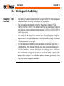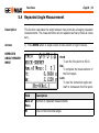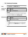
1
GeoMax Zipp10 Series User Manual Version 1.1 Introduction Zipp10 | 2 Introduction Purchase Congratulations on the purchase of a GeoMax Zipp10 series instrument. This manual contains important safety directions as well as instructions for setting up the product and operating it. Refer to "12 Safety Directions" for further information. Read carefully through the User Manual before you switch on the product. Product identification The type and serial number of your product are indicated on the type plate. Enter the type and serial number in your manual and always refer to this information when you need to contact your agency or GeoMax authorised service workshop. Type: _____________________________________ Serial No.: _____________________________________ Symbols The symbols used in this manual have the following meanings: Type Description WARNING Indicates an imminently hazardous situation which, if not avoided, will result in death or serious injury. CAUTION Indicates a potentially hazardous situation or an unintended use which, if not avoided, may result in minor or moderate injury and/or appreciable material, financial and environmental damage. DANGER ) Trademarks Indicates a potentially hazardous situation or an unintended use which, if not avoided, could result in death or serious injury. Important paragraphs which must be adhered to in practice as they enable the product to be used in a technically correct and efficient manner. • Windows is a registered trademark of Microsoft Corporation in the United States and other countries. All other trademarks are the property of their respective owners. Introduction Zipp10 | 3 Zipp10 | 4 Introduction Validity of this manual Description General This manual applies to Zipp10 instruments. Where there are differences between the models they are clearly described. Telescope • • Measuring with P modes: When measuring distances to a reflector with Electronic Distance Measurement (EDM) mode "P", the telescope uses a wide visible red laser beam, which emerges coaxially from the telescope's objective. Measuring with NP modes: Instruments that are equipped with a reflectorless EDM additionally offer the EDM mode "NP". When measuring distances with this EDM mode, the telescope uses a narrow visible red laser beam, which emerges coaxially from the telescope's objective. WARNING 003577_001 Do NOT remove the battery during operation of the instrument, or during the shutdown procedure. This can result in a file system error and data loss! Always switch off the instrument by pressing the On/Off key, and wait until the instrument has shutdown completely before removing the battery. Introduction Zipp10 | 5 Table of Contents Zipp10 | 6 Table of Contents In this manual Chapter 1 Description of the System 1.1 1.2 1.3 2 System Components Container Contents Instrument Components User Interface 2.1 2.2 2.3 2.4 2.5 2.6 3 Page Keyboard Screen Status Icons Softkeys Operating Principles Pointsearch Operation 3.1 3.2 3.3 3.4 Instrument Setup Working with the Battery Data Storage Main Menu 11 11 13 14 16 16 19 20 22 24 26 28 28 34 37 38 3.5 3.6 4 Settings 4.1 4.2 4.3 5 Quick-Survey Application Distance Measurements - Guidelines for Correct Results General Settings EDM Settings System Information Functions 5.1 5.2 5.3 5.4 Overview Angle Offset Distance Offset Repeated Angle Measurement 40 43 46 46 54 58 61 61 63 65 68 6 Coding 70 7 Applications - Getting Started 72 72 73 75 77 79 79 7.1 7.2 7.3 7.4 7.5 Overview Starting an Application Selecting the Job Selecting the Station Selecting the Orientation 7.5.1 Overview Table of Contents Zipp10 | 7 Table of Contents 7.5.2 7.5.3 8 Application 8.1 8.2 8.3 8.4 8.5 8.6 8.7 9 Manual Orientation Orientation with Coordinates Common Fields Data Collect Missing Line Measurement Resection 8.4.1 Starting Resection 8.4.2 Measuring Information 8.4.3 Computation Procedure 8.4.4 Resection Results Set Out Area Remote Elevation Data Management 9.1 9.2 9.3 9.4 Data Manager Exporting Data Importing Data Working with GeoMax Office Zipp10 | 8 80 81 83 83 85 87 91 91 94 95 96 99 104 106 108 108 111 113 114 10 Calibration 10.1 10.2 10.3 10.4 10.5 10.6 Overview Preparation Calibrating Line-of-Sight and Vertical Index Error Calibrating the Level of the Instrument and Tribrach Inspecting the Laser Plummet of the Instrument Servicing the Tripod 11 Care and Transport 11.1 Transport 11.2 Storage 11.3 Cleaning and Drying 12 Safety Directions 12.1 12.2 12.3 12.4 12.5 12.6 General Intended Use Limits of Use Responsibilities Hazards of Use Laser Classification 12.6.1 General 12.6.2 Distancer, Measurements with Reflectors Table of Contents 115 115 117 118 123 125 127 128 128 129 130 132 132 133 135 136 138 144 144 145 Zipp10 | 9 Table of Contents Zipp10 | 10 12.6.3 Distancer, Measurements without Reflectors (NP mode) 12.6.4 Laser Plummet 12.7 Electromagnetic Compatibility EMC 12.8 FCC Statement, Applicable in U.S. 13 Technical Data 13.1 Angle Measurement 13.2 Distance Measurement with Reflectors 13.3 Distance Measurements without Reflectors (Reflectorless mode) 13.4 Conformity to National Regulations 13.4.1 Zipp10 13.5 General Technical Data of the Instrument 13.6 Scale Correction 13.7 Reduction Formulas 147 152 156 158 161 161 162 164 166 166 167 173 176 14 International Limited Warranty 178 15 Glossary 180 Appendix A Index Menu Tree 184 186 1 Description of the System 1.1 System Components Main Components c 003578_001 a Ge o Of M a fic x e b a) Zipp10 instrument b) Computer with GeoMax Office software c) Data transfer Component Description Zipp10 instrument An instrument for measuring, calculating and capturing data. Ideally suited for tasks from simple surveys to complex applications. The instrument can be connected with GeoMax Office to view, exchange and manage data. Firmware The firmware package installed on the instrument. Consists of a standard base operating system. Description of the System Zipp10 | 11 Description of the System Zipp10 | 12 Component Description GeoMax Office software An office software consisting of a suite of standard programs for the viewing, exchanging, managing and post processing of data. Data transfer Data can be always transferred between the instrument and a computer via a data transfer cable. 1.2 Container Contents Container contents a g b h d c i e j 003580_001 Description of the System f a) ZCH301 battery charger b) Instrument with supplied tribrach c) Plumb bob d) ZDC301 USB cable e) Power cable for battery charger f) CD and manual g) Adjustment tools h) ZBA301 battery i) Adapter for charger j) Protective cover Zipp10 | 13 Description of the System Zipp10 | 14 1.3 Instrument Components Instrument components part 1 of 2 a 003581_001 f b c g d e h a) Detachable carrying handle with mounting screw b) Optical sight c) Focusing telescope image d) Eyepiece; focusing graticule e) Vertical drive f) Compartment for USB cable port g) Levelling bubble h) Keyboard Instrument components part 2 of 2 a b c d e f a) Objective with integrated Electronic Distance Measurement (EDM). Exit for laser beam. b) Battery cover c) Horizontal drive d) Footscrew e) Display f) Keyboard 003582 001 Description of the System Zipp10 | 15 Zipp10 | 16 User Interface 2 User Interface 2.1 Keyboard Alphanumeric keyboard a b c d e f g 003583_001 Keys Key a) b) c) d) e) f) g) On/Off key Alphanumeric keypad Shift key ESC key FNC key Enter key Function keys F1 to F4 Description Alphanumeric keypad for entry of text and numerical values. Key Description On/Off key. Turns instrument off when pressed for 2 s. Accesses the Main Menu when pressed for 1 s. Shift Shift key. Accesses the second level of keys. Refer to "Key combinations". ESC key. Quits a screen or edit mode without saving changes. Returns to next higher level. FNC key. Quick-access to measurement supporting functions. ENTER key. Confirms an entry and continues to the next field. Function keys that are assigned the variable functions displayed at the bottom of the screen. Key combinations Key Function + Hold SHIFT while pressing 8. Inserts a character at the curser position, moves the cursor up or selects a page. + Hold SHIFT while pressing 6. Moves the cursor to the right. Shift Shift User Interface Zipp10 | 17 Zipp10 | 18 User Interface Key Function + Hold SHIFT while pressing 2. Deletes the character at the cursor position, moves the cursor down or selects a page. + Hold SHIFT while pressing 4. Moves the cursor to the left. + Hold SHIFT while pressing 0. Switches to coordinate measurement mode when in Quick-Survey or Data Collect. + Hold SHIFT while pressing . Switches to distance measurement mode when in Quick-Survey or Data Collect. + Hold SHIFT while pressing ±. Switches to angle measurement mode when in Quick-Survey or Data Collect. Shift Shift Shift Shift Shift 2.2 Screen Screen a b c d e f ) a) b) c) d) e) f) PPM value Title of screen Status icons Focus in screen. Active field Fields Softkeys All shown screens are examples. It is possible that local firmware versions are different to the basic version. User Interface Zipp10 | 19 User Interface Zipp10 | 20 2.3 Status Icons Description Icons The icons provide status information related to basic instrument functions. Depending on the firmware version, different icons may be displayed. Icon Description The battery symbol indicates the level of the remaining battery capacity in 25% steps. Compensator is on. Compensator is off. P EDM mode for measuring to prisms. NP EDM mode for measuring to all targets. EDM mode for measuring to reflective foils. EDM type for measuring to 360° prism. EDM type for measuring to 360° Mini prism. Icon Description EDM type for measuring to Custom prism. EDM type for measuring to Mini prism. EDM type for measuring to MiniJP prism. EDM type for measuring to Round prism. A double arrow indicates that a field has a selectable list. Up and down arrows indicate that several screens are available, which are accessed using Shift + 2 or a softkey. Indicates that telescope position is face I. Indicates that telescope position is face II. User Interface Zipp10 | 21 User Interface Zipp10 | 22 2.4 Softkeys Description Common softkey functions Softkeys are selected using the relevant F1 to F4 function key. This chapter describes the functionality of the common softkeys used by the system. The more specialised softkeys are described where they appear in the program chapters. Key Description ALPH To change the keypad operation to alphanumerical. NUM. To change the keypad operation to numerical. ALL To start distance and angle measurements and save the measured values. BACK To return to the last active screen. ENZ To open the manual coordinate entry screen. EDM To view and change EDM settings. Refer to "4.2 EDM Settings". MEAS To start distance and angle measurements without saving the measured values. Key Description OK If entry screen: Confirms measured or entered values and continues the process. If message screen: Confirms message and continues with selected action or returns to the previous screen to reselect an option. P/NP To toggle between P and NP EDM modes. LIST To display the list of available points. REC To save the displayed values. DEFL To reset all editable fields to their default values. SRCH To search for an entered point. VIEW To display the coordinate and job details of the selected point. To display the next softkey level or select the next page. User Interface Zipp10 | 23 User Interface Zipp10 | 24 2.5 Operating Principles Turn instrument on/off Use the On/Off key. Alphanumeric keypad The alphanumerical keypad is used to enter characters directly into editable fields. • Numeric fields: Can only contain numerical values. By pressing a key of the keypad the number will be displayed. • Alphanumeric fields: Can contain numbers and letters. By pressing a key of the keypad the first character written above that key will be displayed. By pressing several times you can toggle through the characters. For example: 1->S->T->U->1->S.... Edit fields ) + ESC deletes any change. Moves the cursor to the left + Moves the cursor to the right. Inserts a character at the cursor position. + + Deletes the character at the cursor position. ) Special characters In edit mode the position of the decimal place cannot be changed. The decimal place is skipped. Character Description * Used as wildcards in search fields for point numbers or codes. Refer to "2.6 Pointsearch". +/- In the alphanumeric character set "+" and "-" are treated as normal alphanumeric characters with no mathematical function. ) "+" / "-" only appear in front of an entry. In this example selecting 2 on an alphanumeric keyboard would start the Resection application. User Interface Zipp10 | 25 Zipp10 | 26 User Interface 2.6 Pointsearch Description Pointsearch is a function used by applications to find measured or fixed points in the memory storage. The pointsearch is limited to the current job. It is not possible to search the whole storage. The search procedure always finds fixed points before measured points that fulfil the same search criteria. If several points meet the search criteria, then the results are ordered according to the entry date. The instrument finds the most recent fixed point first. Direct search By entering an actual point number, for example P404, and pressing OK, all points within the current job and with the corresponding point number are found. OK To search for matching points within the current job. Wildcard search The wildcard search is indicated by a "*". The asterisk is a place holder for any following sequence of characters. Wildcards should be used if the point number is not fully known, or to search for a batch of points. Examples of point searches * A A* *1 A*1 All points All points All points All points All points example, are found. with exactly the point number "A" are found. starting with "A" are found, for example, A9, A15, ABCD, A2A. containing only one "1" are found, for example, 1, A1, AB1. starting with "A" and containing only one "1" are found, for A1, AB1, A51. User Interface Zipp10 | 27 Zipp10 | 28 Operation 3 Operation 3.1 Instrument Setup Description ) Tripod This topic describes an instrument setup over a marked ground point using the laser plummet. It is always possible to set up the instrument without the need for a marked ground point. Important features • It is always recommended to shield the instrument from direct sunlight and avoid uneven temperatures around the instrument. • The laser plummet described in this topic is built into the vertical axis of the instrument. It projects a red spot onto the ground, making it appreciably easier to centre the instrument. • The laser plummet cannot be used with a tribrach equipped with an optical plummet. ) When setting up the tripod pay attention to ensuring a horizontal position of the tripod plate. Slight corrections of inclination can be made with the foot screws of the tribrach. Larger corrections must be done with the tripod legs. Loosen the clamping screws on the tripod legs, pull out to the required length and tighten the clamps. a a) In order to guarantee a firm foothold sufficiently press the tripod legs into the ground. b) When pressing the legs into the ground note that the force must be applied along the legs. b Careful handling of tripod. • Check all screws and bolts for correct fit. • During transport always use the cover supplied. • Use the tripod only for surveying tasks. Operation Zipp10 | 29 Zipp10 | 30 Operation Setup step-by-step 7 2 3 6 1 1 1 5 5 4 5 03610_001 1 2 3 4 5 6 Extend the tripod legs to allow for a comfortable working posture. Position the tripod over the marked ground point, centring it as best as possible. Fasten the tribrach and instrument onto the tripod. Turn on the instrument, and, if tilt correction is set to 1- or 2-axis, the laser plummet will be activated automatically, and the Level & Plummet screen appears. Otherwise, press FNC from within any application and select Lev & Plummet. Move the tripod legs (1) and use the tribrach footscrews (6) to center the plummet (4) over the ground point. Adjust the tripod legs (5) to level the tubular level (7). By using the electronic level, turn the tribrach footscrews (6) to precisely level the instrument. Refer to "Level up with the electronic level step-bystep". 7 8 Level up with the electronic level step-by-step Center the instrument precisely over the ground point by shifting the tribrach on the tripod plate (2). Repeat steps 6 and 7 until the required accuracy is achieved. The electronic level can be used to precisely level up the instrument using the footscrews of the tribrach. 1) Turn the instrument until the tubular level is parallel to two footscrews. 2) Center the level on the instrument approximately by turning the footscrews of the tribrach. 3) Turn on the instrument, and, if tilt correction is set to 1- or 2-axis, the laser plummet will be activated automatically, and the Level & Plummet screen appears. Otherwise, press FNC from within any application and select Lev & Plummet. 4 5 Center the electronic level of the first axis by turning the two footscrews. Center the electronic level for the second axis by turning the last footscrew. When the electronic level is centered and both axes are within the tolerance limit, the instrument has been levelled up. ) Operation Zipp10 | 31 Zipp10 | 32 Operation 6 Change the intensity of the laser plummet Accept with OK. External influences and the surface conditions may require the adjustment of the intensity of the laser plummet. In the Level & Plummet screen, adjust the intensity of the laser plummet using the navigation keys. The laser can be adjusted in 25% steps as required. + + 003611_001 Min 50% 75% Max Under some circumstances the laser dot is not visible, for example over pipes. In this case, using a transparent plate enables the laser dot to be seen and then easily aligned to the center of the pipe. Position over pipes or holes Operation Zipp10 | 33 Operation Zipp10 | 34 3.2 Working with the Battery Charging / firsttime use • • • • • The battery must be charged prior to using it for the first time because it is delivered with an energy content as low as possible. The permissible temperature range for charging is between 0°C to +40°C/+32°F to +104°F. For optimal charging we recommend charging the batteries at a low ambient temperature of +10°C to +20°C/+50°F to +68°F if possible. It is normal for the battery to become warm during charging. Using the chargers recommended by GeoMax, it is not possible to charge the battery if the temperature is too high. For new batteries or batteries that have been stored for a long time (> three months), it is effectual to make only one charge/discharge cycle. For Li-Ion batteries, a single discharging and charging cycle is sufficient. We recommend carrying out the process when the battery capacity indicated on the charger or on a GeoMax product deviates significantly form the actual battery capacity available. Change the battery step-by-step Remove the battery holder from the instrument (1). 2 Remove the battery from the battery holder (2). 1 003613_001 Insert the new battery into the battery holder (3), ensuring that the contacts are facing outward. The battery should click into position. 3 Insert the battery holder back into the battery compartment (4). 4 003614_001 Operation Zipp10 | 35 Operation WARNING Zipp10 | 36 If charged or discharged, batteries not recommended by GeoMax may be damaged. They may burn and explode. Precautions: Only charge and discharge batteries recommended by GeoMax. 3.3 Data Storage Description An internal memory is included in all instruments. The firmware stores all data in jobs in a database in the internal memory. Data can then be transferred to a computer or other device for post processing via a cable connected to the USB port. Refer to "9 Data Management" for further information on data management and data transfer. Operation Zipp10 | 37 Zipp10 | 38 Operation 3.4 Main Menu Description The MAIN MENU is the starting place for accessing most functionality of the instrument. It is displayed when pressing the Menu key. MAIN MENU Description of the MAIN MENU functions Function Description Data Collect To select and start the Data Collect application. Refer to "8.2 Data Collect". Set out To select and start the Set out application. Refer to "8.5 Set Out". Apps To select and start applications. Refer to "8 Application". Function Description Data Manager To manage jobs, data, codelists and system memory. Refer to "9 Data Management". Settings To change EDM configurations and general instrument settings or access system information. Refer to "4 Settings". Calibration To calibrate the instrument. Refer to "10 Calibration". Operation Zipp10 | 39 Zipp10 | 40 Operation 3.5 Quick-Survey Application Description After switching on, the instrument is immediately ready for measuring. Access The QUICK-SURVEY screen is the default start screen after the instrument is turned on. QUICK-SURVEY ) Depending on the measuring mode, a different screen is displayed. The procedure for the Quick-Survey is identical to the procedure for the application Data Collect available under the Main Menu . Therefore this procedure is only described once within the application chapter. Refer to "8.2 Data Collect". Quick-Survey softkeys Depending on the selected measuring mode, different softkeys are displayed on the Quick-Survey screen. Measuring Mode Softkey Description Coordinate Measurement P/NP Toggle between prism and non prism mode. OFFS Enter offset function. MEAS Trigger measurement. hr Enter target height. hi Enter station height. STN Enter station coordinates. m/ft Toggle between distance unit meter and feet. EDM Enter EDM settings. P/NP Toggle between prism and non prism mode. OFFS Enter offset function. MEAS Trigger measurement. m/ft Toggle between distance unit meter and feet. S/O Enter Set out application. Distance Measurement Operation Zipp10 | 41 Zipp10 | 42 Operation Measuring Mode Angle Measurement Softkey Description EDM Enter EDM settings. HZ=0 Set horizontal angle to 0. Lock Lock the horizontal angle. HZ=? Enter and set a horizontal angle. COMP Enter compensator settings. RMEA Enter angle repeat measurement. V% Toggle between vertical angle unit % and gon. R/L Toggle between horizontal angle left and horizontal angle right. VA Set vertical angle to Horizon = 0°. ZA Set vertical angle to Zenith = 0°. 3.6 Distance Measurements - Guidelines for Correct Results Description A laser distancer (EDM) is incorporated into the Zipp10 instruments. In all versions, the distance can be determined by using a visible red laser beam which emerges coaxially from the telescope objective. There are two EDM modes: • Prism measurements (P) • Reflectorless measurements (NP) • When a distance measurement is triggered, the EDM measures to the object which is in the beam path at that moment. If a temporary obstruction, for example a passing vehicle, heavy rain, fog or snow is between the NP measurements Operation Zipp10 | 43 Operation • • • P measurements • • • • • Zipp10 | 44 instrument and the point to be measured, the EDM may measure to the obstruction. Be sure that the laser beam is not reflected by anything close to the line of sight, for example highly reflective objects. Avoid interrupting the measuring beam while taking reflectorless measurements or measurements using reflective foils. Do not measure with two instruments to the same target simultaneously. Accurate measurements to prisms should be made in P-Standard mode. Measurements to strongly reflecting targets such as traffic lights in Prism mode without a prism should be avoided. The measured distances may be wrong or inaccurate. When a distance measurement is triggered, the EDM measures to the object which is in the beam path at that moment. If for example people, cars, animals, or swaying branches cross the laser beam while a measurement is being taken, a fraction of the laser beam is reflected from these objects and may lead to incorrect distance values. Measurements to prisms are only critical if an object crosses the measuring beam at a distance of 0 to 30 m and the distance to be measured is more than 300 m. In practice, because the measuring time is very short, the user can always find a way of avoiding unwanted objects from interfering in the beam path. Red laser to reflector foil • • The visible red laser beam can also be used to measure to reflective foils. To guarantee the accuracy the red laser beam must be perpendicular to the reflector foil and it must be well adjusted. Make sure the additive constant belongs to the selected target (reflector). Operation Zipp10 | 45 Zipp10 | 46 Settings 4 Settings 4.1 General Settings Access 1) 2) 3) Select Setting from the MAIN MENU. Select General from the SETTINGS menu. Press F4 to scroll through the screens of available settings. SETTINGS Field Description Contrast 0% to 100% Sets the display contrast in 10% steps. Tilt Corr. OFF Tilting compensation deactivated. 1-Axis Vertical angles refer to the plummet line. Field Description 2-Axis ) Beep Sect Beep AngUnit Settings Vertical angles refer to the plummet line and the horizontal directions are corrected by the standing axis tilt. For corrections depending on the HA Corr: setting, refer to the table "Tilt and horizontal corrections". If the instrument is used on an unstable base, for example a shaking platform or ship, the compensator should be deactivated. This avoids the compensator drifting out of it's measuring range and interrupting the measuring process by indicating an error. The beep is an acoustic signal after each key stroke. Normal Normal volume. OFF Beep is deactivated. ON Sector Beep sounds at right angles (0°, 90°, 180°, 270° or 0, 100, 200, 300 gon). OFF Sector Beep is deactivated. Sets the units shown for all angular fields. Zipp10 | 47 Zipp10 | 48 Settings Field ) MinRead Description gon Gon. Possible angle values: 0 gon to 399.999 gon dec. de Degree decimal. Possible angle values: 0° to 359.999° mil Mil. Possible angle values: 0 to 6399.99mil. °'" Degree sexagesimal. Possible angle values: 0° to 359°59'59'' The setting of the angle units can be changed at any time. The actual displayed values are converted according to the selected unit. Sets the number of decimal places shown for all angular fields. This is for data display and does not apply to data export or storage. For Angle Unit ° ' '': (0° 00' 01" /0° 00' 05"/0° 00' 10"). Dec.de: (0.0001 / 0.0005 / 0.001). Gon: (0.0001 / 0.0005 / 0.001). Mil: (0.01 / 0.001 / 0.05 / 0.1). Field Description DisUnit Sets the units shown for all distance and coordinate related fields. meter Meters [m]. ft (US) US feet [ft]. ft (INT) International feet [fi]. ft-in/16 US feet-inch-1/16 inch [ft]. Disp ill. ON or OFF Sets the screen illumination on or off. HA Corr. ON Horizontal corrections are activated. For normal operation the horizontal correction should remain active. Each measured horizontal angle will be corrected, depending on the vertical angle. For corrections depending on the Tilt Corr: setting, refer to the table "Tilt and horizontal corrections". OFF Horizontal corrections are deactivated. Right Set horizontal angle to clockwise direction measurement. HA Incr. Settings Zipp10 | 49 Zipp10 | 50 Settings Field Description Left VA-Setting Set horizontal angle to counter-clockwise direction measurement. Counter-clockwise directions are displayed but are saved as clockwise directions. Sets the vertical angle. Zenith 45° 0° Zenith=0°; Horizon=90°. 90° 0° 27 ° 180 Horizon 5° ° +90 +4 0° ° -45 ° 180 ° - 90 Zenith=90°; Horizon=0°. Vertical angles are positive above the horizon and negative below it. Description Slope % 71° --.--% 34” Slope % Auto-OFF Temp. Unit Press. Unit ) Enable The instrument switches off after 20 minutes without any activity, for example no key pressed or vertical and horizontal angle deviation is ±3". Disabl Automatic switch-off is deactivated. ) Battery discharges quicker. Sets the units shown for all temperature fields. °C Degree Celsius. °F Degree Fahrenheit. Sets the units shown for all pressure fields. hPa Settings +100% n go 0 -5 ,5 gon -79 --.--% 45°=100%; Horizon=0°. Vertical angles are expressed +18 % in % with positive above the 20° 360s 0° horizon and negative below gon ±VA it. -100 % The % value increases -300 % rapidly. --.--% appears on the display above 300%. +300 % 45 ° Field Hecto Pascal. Zipp10 | 51 Zipp10 | 52 Settings Field Description Data Conf. StartUp DP Tilt and horizontal corrections mbar Millibar. mmHg Millimeter mercury. inHg Inch mercury. Sets the prompting for data confirmation. ON Data confirmation is activated. OFF Data confirmation is deactivated. Sets which screen is accessed after the instrument is turned on. Angle Startup with angle measuring screen. Dist Startup with distance measuring screen. Setting Correction Tilt HoriIncline correction zontal longitucorrection dinal Incline transversal Horizontal collimation Tilting axis Off No Yes Yes On No Setting Correction Tilt HoriIncline correction zontal longitucorrection dinal Incline transversal Horizontal collimation Tilting axis On On Yes Yes Yes Yes Off Off No No No No On Off Yes No No No Settings Zipp10 | 53 Zipp10 | 54 Settings 4.2 EDM Settings Description The settings on this screen define the active EDM, Electronic Distance Measurement. Different settings for measurements are available with Reflectorless (NP) and Prism (P) EDM modes. Access 1) Select Setting from the MAIN MENU. 2) Select EDM from the SETTINGS menu. EDM SETTINGS AMOS To enter atmospheric data ppm. PPM To enter an individual ppm value. SCAL To enter projection scale details. SIGN To view EDM Signal reflection value. FREQ To view the EDM frequency. Field Description Mode P-Std Fine measuring mode for high precision measurements with prisms. P-Quick Quick measuring mode with prisms, with higher measuring speed and reduced accuracy. P-Cont For continuous distance measurements with prisms. NP-Std For distance measurements without prisms. NP-Cont For continuous distance measurements without prisms. Foil For distance measurements using Retro reflective targets. Round Standard prism Constant: -34.4 mm Mini Mini prism Constant: -16.9 mm MinJP MinJP Constant: 0.0 mm 360° 360° prism Constant: -11.3 mm 360° Mini 360° Mini prism Constant: -4.4 mm Custom The user can define their own prism. Constants can be entered in mm in Constant. Type Settings Zipp10 | 55 Zipp10 | 56 Settings Field ATMOSPHERIC DATA ENTRY Description Foil Constant: 0.0 mm None NP-modes Constant: 0.0 mm Constant This field displays the absolute prism constant for the selected Type: Where Type: is Custom this field becomes editable to set a user defined constant. Input can only be made in mm. Limit value: -999.9 mm to +999.9 mm. Laser OFF Visible laser beam is deactivated. ON Visible laser beam for visualising the target point is activated. This screen enables the entry of atmospheric parameters. Distance measurement is influenced directly by the atmospheric conditions of the air in which the measurements are taken. In order to take these influences into consideration distance measurements are corrected using atmospheric correction parameters. The refraction correction is taken into account in the calculation of the height differences and the horizontal distance. Refer to "13.6 Scale Correction" for the application of the values entered in this screen. ) When PPM=0 is selected, the GeoMax standard atmosphere of 1013 hPa, 12°C, and 60% relative humidity will be applied. Free-PPM Entry This screen enables the entry of individual scaling factors. Coordinates and distance measurements are corrected with the PPM parameter. Refer to "13.6 Scale Correction" for the application of the values entered in this screen. PROJECTION SCALE This screen enables entry of the scale of projection. Coordinates are corrected with the PPM parameter. Refer to "13.6 Scale Correction" for the application of the values entered in this screen. EDM SIGNAL REFLECTION This screen tests the EDM signal strength (reflection strength) in steps of 1%. Enables optimal aiming at distant, barely visible, targets. A percentage bar and a beeping sound, indicate the reflection strength. The faster the beep the stronger the reflection. Settings Zipp10 | 57 Zipp10 | 58 Settings 4.3 System Information Description The System Information screen displays instrument, system and firmware information, as well as settings for the date and time. Please provide the instrument-related information, such as instrument type and serial number, as well as the firmware version and build number when contacting support. ) Access 1) Select Setting from the MAIN MENU. 2) Select System Info. from the SETTINGS MENU. SYSTEM INFORMATION This screen displays information about the instrument and operating system. SW To display details of the firmware package installed on the instrument. DATE To change the date and format. TIME To change the time. Field Description Type Displays the instrument type. S/N Displays the serial number of the instrument. Time Displays the time. Next step Press SW to view the firmware package information. SOFTWARE-INFO Field Description FW ver. Displays the firmware version number installed on the instrument. Build Displays the build number of the firmware. Settings Zipp10 | 59 Zipp10 | 60 Settings Field Description EDM-Firm Displays the version number of the EDM firmware. Application Information Displays a list of the applications available on the instrument. 5 Functions 5.1 Overview Description Functions Functions can be accessed by pressing FNC from any measurement screen. FNC opens the functions menu and a function can be selected and activated. Function Description Lev & Plummet Activates the laser plummet and electronic level. Illu. ON/OFF Activates and deactivates the screen illumination light. Data Confirm Sets the prompting for data confirmation. Del Last Obs. Deletes the last recorded data block. Deleting the last record is not reversible! Only records recorded in Data Collect can be deleted. Laserbeam Activates/deactivates the visible laser beam for illuminating the target point. Settings Refer to "4 Settings". P/NP Change Changes between the two EDM modes. Refer to "4.2 EDM Settings". Functions ) Zipp10 | 61 Zipp10 | 62 Functions Function Description Compensator Opens the Compensator screen. Refer to "4.1 General Settings". 5.2 Angle Offset Description This function calculates the target point coordinates if it is not possible to set up the reflector, or to aim at the target point directly. The offset point and the measurement point must have the same distance to the instrument. Access 1) Press OFFS when in distance or coordinate screen of Data Collect or QuickSurvey. 2) Select Angle Offset from the Select method menu. ANGLE OFFSET Field Description HR Horizontal angle. VA Vertical angle. Functions Zipp10 | 63 Zipp10 | 64 Functions Field Description VD Height to the point. Next step • Press OK and measure the distance. Aim at the second target and press OK to calculate the offset point. 5.3 Distance Offset Description This function calculates the target point coordinates if it is not possible to set up the reflector, or to aim at the target point directly. The offset values (length, trav. and/or height offset) can be entered. The values for the angles and distances are calculated to determine the target point. OP T_Off L_Off - MP L_Off+ T_Off+ MP OP T_Off L_Off Functions Measurement point Offset point Length offset Cross offset Zipp10 | 65 Zipp10 | 66 Functions Access 1) Press OFFS when in distance or coordinate screen of Data Collect or QuickSurvey. 2) Select Dist. Offset from the Select method menu. DISTANCE OFFSET Field Description TrOff Perpendicular offset. Positive if the offset point is to the right of the measured point. Loff Longitudinal offset. Positive if the offset point is further away than the measured point. HtOff Height offset. Positive if the offset point is higher than the measured point. ) The offset values are always remembered when the application is quit. Next step • Press OK and measure the distance. Confirm the measurement with OK to calculate the offset point. Functions Zipp10 | 67 Zipp10 | 68 Functions 5.4 Repeated Angle Measurement Description This function calculates the angle between two points by averaging repeated measurements. The measurements can be repeated as many times as necessary. Access 1) Press RMEA when in angle screen of Data Collect or Quick-Survey. REPEATED ANGLE MESUREMENT Hz=0 To set the first point to HZ=0. Rel. To complete the measurement of the first target. Lock To lock the horizontal angle and start to remeasure the first point. Field Description Num. of Meas Number of repeated measurements. Ht Total of the horizontal angle. Field Description Hm Mean of the repeated horizontal angle measurements. Next step • Repeat the measurements as many times as necessary. Press ESC to exit the function. Functions Zipp10 | 69 Coding Zipp10 | 70 6 Coding Description Codes contain information about recorded points. With the help of coding, points can be assigned to a particular group simplifying later processing. Codes are stored in codelists, with each codelist supporting a maximum of 200 codes. GSI coding Codes are always stored as free codes (WI41-49), that means that codes are not directly linked to a point. They are stored before the measurement. A code is always recorded for each measurement as long as the code is displayed in the Code: field. For a code not to be recorded, the Code: field must be cleared. Access Select Data Manager from the MAIN MENU and choose Code Library. CODE-LIBRARY NEW To enter a new code. DEL To delete the selected code. Extend codes Field Description SRCH Code name. After entry, the firmware searches for a matching code name, and displays these in the code field. Code List of existing code names. REM Additional remarks. Text 1 to Text 8 More information lines, freely editable. Used to describe attributes of the code. To each code a description and a maximum of 8 attributes with up to 12 characters each can be assigned. Existing code attributes are displayed in fields Text 1: to Text 8:. Coding Zipp10 | 71 Applications - Getting Started Zipp10 | 72 7 Applications - Getting Started 7.1 Overview Description Applications are predefined programs, that cover a wide spectrum of surveying duties and facilitate daily work in the field. The following applications are available: • Data Collect • Missing Line Measurement • Resection • Set Out • Area • Remote Elevation 7.2 Starting an Application Access 1) Select Apps from the MAIN MENU. Data Collect and Set out can be directly accessed over the Main Menu. 2) Press a function key, F1 - F4, to select the specified application in the APPLICATIONS menu. Pre-settings screens Pre-settings for Data Collect is shown as an example. Any additional settings for particular applications are explained within the chapters for those applications. F1-F4 To select menu item. Field Description Select Job To define the job where data will be saved. Refer to "7.3 Selecting the Job". Applications - Getting Started Zipp10 | 73 Applications - Getting Started Zipp10 | 74 Field Description Select Stn To define the current position of the instrument station. Refer to "7.4 Selecting the Station". Select Ori. To define the orientation and horizontal direction of the instrument station. Refer to "7.5 Selecting the Orientation". GO! Starts the selected application. 7.3 Selecting the Job Description All data is saved in Jobs, like file directories. Jobs contain measurement data of different types, for example measurements, codes, fixed points, or stations. Jobs are individually manageable and can be exported, edited or deleted separately. Access Select Select Job in Pre-settings screen. SELECT JOB NEW To create a new job. Field Description Job Name of an existing job to be used. User Name of user, if entered. Date Date the selected job was created. Applications - Getting Started Zipp10 | 75 Applications - Getting Started Field Description Time Time the selected job was created. Zipp10 | 76 Next step • Either, press OK to continue with the selected job. • Or, press NEW to open the NEW JOB screen and create a new job. Recorded data Once a job is set up, all subsequent recorded data will be stored in this job. If no job was defined and an application was started and a measurement was recorded, then the system automatically creates a new job and names it "DEFAULT". Next step Press OK to confirm the job and return to the Pre-Settings screen. 7.4 Selecting the Station Description All measurements and coordinate computations are referenced to the set station coordinates. The station coordinates that are set must include: • at least grid coordinates (E, N), and • the station height, if required. The coordinates can be entered manually or selected from the memory. STn.X STn.Y 03617_001 Access Directions X Easting Y Northing Z Height Station coordinates Stn.X Easting coordinate of station Stn.Y Northing coordinate of station Select Select Stn in the Pre-settings screen. Applications - Getting Started Zipp10 | 77 Applications - Getting Started Zipp10 | 78 Station input ) Next step Field Description Stn Station name of a previously saved station position. If no station was set and an application was started, or if in Survey and a measurement was recorded, then the last station is set as the current station. The Inst.Ht. field appears once the station coordinates have been entered. Enter the instrument height if desired and press OK to return to the PreSettings screen. 7.5 Selecting the Orientation 7.5.1 Overview Description All measurements and coordinate computations are referenced to the orientation of the set station. The orientation can be entered manually or determined from points that are either measured or selected from the memory. Access Select Select Ori. in the Pre-settings screen and choose: • Angle to enter a new bearing. Refer to "7.5.2 Manual Orientation". • Coordinates to calculate and set the orientation using existing coordinates. Applications - Getting Started Zipp10 | 79 Zipp10 | 80 Applications - Getting Started 7.5.2 Manual Orientation Access Select Angle in the ORIENTATION screen. MANUAL ANGLE SETTING HA=0 To set the bearing to 0. Next step Field Description hr Height of the reflector. Brg. Horizontal direction of the station. • • Press YES set the orientation and return to the Pre-Settings screen. Press NO return to the Pre-Settings screen. No changes will be saved. 7.5.3 Orientation with Coordinates Access Orientation with coordinates Select Coordinates in the ORIENTATION screen. Field Description BS ID Point ID of the backsight point. Next step Find an existing backsight point in the pointsearch or enter ENZ coordinates for a new point. Press OK to continue to Sight target point. Sight target point Field Description Brg. Horizontal direction of the station. Next step • Press YES to set the orientation and return to the Pre-Settings screen. • Press NO to return to the ORIENTATION screen. No changes will be saved. Applications - Getting Started Zipp10 | 81 Applications - Getting Started ) Next step Zipp10 | 82 If no orientation was set and an application was started, or if in Quick-Survey and a measurement was made, then the current horizontal direction is set as the orientation. Select GO! to begin the application. 8 Application 8.1 Common Fields Description of fields The following table describes common fields that are found within the firmware applications. These fields are described here once and not repeated in the application chapters unless the field has a specific meaning within that application. Field Description Pt, Pt 1 Point ID of the point. hr Height of the reflector. HR Horizontal direction to the point. VA Vertical angle to the point. HD Horizontal distance to the point. SD Slope distance to the point. VD Height to the point. E Easting coordinate of the point. N Northing coordinate of the point. Application Zipp10 | 83 Zipp10 | 84 Application Field Description Z Height coordinate of the point. 8.2 Data Collect Description Data Collect is an application used for the measurement of an unlimited number of points. It is comparable to Quick-Survey from the start screen, but data is recorded and it includes pre-settings for the job, station and orientation prior to beginning a survey. Access 1) Select Data Collect from the MAIN MENU. 2) Complete application pre-settings. Refer to "7 Applications - Getting Started". SURVEYING Application Zipp10 | 85 Application Next step Zipp10 | 86 Field Description Code Code name. This text is stored with the corresponding measurement. The code can be related to a codelist. A codelist on the instrument is not necessary. • • Either, press ALL to record another point. Or, press ESC to exit the application. 8.3 Missing Line Measurement Description Missing Line Measurement is an application used to compute slope distance, horizontal distance, height difference and azimuth of two target points which are either measured, selected from the memory, or entered using the keypad. Missing Line Measurement methods The user can choose between two different methods: • Polygonal: P1-P2, P2-P3, P3-P4. • Radial: P1-P2, P1-P3, P1-P4. Polygonal method T101 T202 T303 SD 1-2 SD 1-2 SD 2-3 Application 1st target point 2nd target point 3rd target point Slope distance from T101T202 SD 2-3 Slope distance from T202T303 Az 1-2 Azimuth from T101-T202 Az 2-3 Azimuth from T202-T303 Zipp10 | 87 Zipp10 | 88 Application Radial method SD 1-2 SD 1-3 CP SD 1-4 1-4 SD 1-2 SD 1-3 SD 1-4 Az 1-2 Az 1-3 Az 1-4 CP Target points Slope distance from 1-2 Slope distance from 1-3 Slope distance from 1-4 Azimuth from 1-2 Azimuth from 1-3 Azimuth from 1-4 Center point Access 1) Select Apps from the MAIN MENU. 2) Select MISSING LINE from the APPLICATIONS menu. 3) Complete application pre-settings. Refer to "7 Applications - Getting Started". 4) Select POLYGON or RADIAL. Missing line measurements After completing the measurements required, the Missing Line result screen will appear. NewT To calculate an additional line. Application starts again at point 1. NewP To set point 2 as the starting point of a new line. A new point 2 must be measured. RADI To switch to radial method. MISSING LINE RESULT - Polygonal method Field Description d. HD Horizontal distance between point 1 and point 2. dz Height difference between point 1 and point 2. HZ Azimuth between point 1 and point 2. Application Zipp10 | 89 Zipp10 | 90 Application MISSING LINE RESULT - Radial method Next step CtrP To calculate an additional line. Application starts again at point 1. EndP To measure a new point 2. POLY To switch to polygonal method. Field Description d. HD Horizontal distance between point 1 and point 2. dz Height difference between point 1 and point 2. HZ Azimuth between point 1 and point 2. Press ESC to exit the program. 8.4 Resection 8.4.1 Starting Resection Description Resection is an application used to determine the instruments position from measurements to known points. A minimum of two known points and a maximum of 5, can be used to determine the position. Z Access 1) Select Apps from the MAIN MENU. 2) Select RESECTION from the APPLICATIONS menu. 3) Complete application pre-settings. Refer to "7 Applications - Getting Started". 4) Select Select Acc.to set accuracy limit: Application Zipp10 | 91 Application Zipp10 | 92 • ON to activate a warning message if the calculated standard deviation exceeds the limit. • Set the accuracy limits for the Easting, Northing and Height coordinates and the standard deviation angle. • OFF to deactivate that a warning message is shown. • Press OK to save the limits and return to the Pre-settings screen. 5) Select GO! to begin the application. Enter target data Enter the name of the station and the height of the instrument in the Station data screen and press OK. Next step To access the Sight target point screen: • Press OK after entering the target data fields in the Target data screen. Sight target point In the Sight target point screen: 2 / I: Indicates that the second point was measured in face I. 2 / I II: Indicates that the second point was measured in faces I and II. CALC To calculate and display the station coordinates, if at least two points and a distance were measured. NxPt To return to the Enter target data screen to select the next known point. Next step • Either, press NxPt to measure the next known point. • Or, press CALC to calculate the station position. Application Zipp10 | 93 Application Zipp10 | 94 8.4.2 Measuring Information Measurement sequences The following measurement sequences are possible: • Horizontal direction and vertical-angles only (resection) • Distance and horizontal direction and vertical-angle • Horizontal direction and vertical-angles to some point(s) and horizontal direction and vertical angles plus distance to other point(s). Single face I, single face II, or dual face I and II measurements are always possible. No specific point sequence or specific face sequences are required. Dual face measurements When measuring the same target in both faces, the reflector height may not be changed when observing in the second face. Error checks are made for dual face measurements to ensure the same point is sighted with the other face. ) • • Measurements not included in computations If a target point is measured several times in the same face, only the last valid measurement is used for computation. For the calculation of the station position, measured target points can be re-measured. Target points with 0.000 height are discarded for height processing. If a target point has a valid height of 0.000 m, use 0.001 m to include it for height processing. 8.4.3 Computation Procedure Description The measuring procedure automatically determines the method of evaluation, for example resection or three point resection. If more than the minimum required measurements are performed, the procedure uses a least squares adjustment to determine the 3D position and averages orientation and height measurements. • The original averaged face I and face II measurements are used for the computation process. • All measurements are treated with the same accuracy, whether these are measured in single or dual face. • Easting and Northing are determined by the least squares method, which includes standard deviation and improvements for horizontal direction and horizontal distances. • The final height (H) is computed from averaged height differences based on the original measurements. • The horizontal direction is computed with the original averaged face I and face II measurements and the final computed plan position. Application Zipp10 | 95 Application Zipp10 | 96 8.4.4 Resection Results Access Press CALC. from the Sight target point screen after at least two points and a distance have been measured. STATION COORDINATES This screen displays calculated station coordinates. The final computed results are Easting, Northing and Height coordinates of the present instrument station, including the instrument height. Standard deviations and residuals for accuracy assessments are provided. RESI To display residuals. Refer to "Target Residuals". S. D. To display the standard deviation of the coordinates and angle. ) If the instrument height was set to 0.000 in the setup screen, then the station height refers to the height of the tilting axis. Next step Press RESI to display the target residuals. Target Residuals The TARGET RESIDUALS screen displays the computed residuals for the horizontal and vertical distances and the horizontal direction. Residual = Calculated value - Measured value. Messages The following are important messages or warnings that may appear. Messages Description Invalid point data! This message occurs if the selected target point has no Easting or Northing coordinate. Max 5 points supported! 5 points have already been measured and another point is selected. The system supports a maximum of 5 points. No position recorded – due to bad data! – Application The measurements may not allow final station coordinates (Eastings, Northings) to be computed. Either the target height is invalid or insufficient measurements are available to compute a final station height. Zipp10 | 97 Zipp10 | 98 Application Messages Description Remeasure point in Face I and II. – – Next step This error occurs if a point was measured in one face and the measurement in the other face differs by more than 180° ± 0.9° for the horizontal angle. This error occurs if a point was measured in one face and the measurement in the other face differs by more than 360° - VA ± 0.9° for the vertical angle. Press OK to return to the APPLICATION menu. 8.5 Set Out Description Set Out is an application used to place marks in the field at predetermined points. These predetermined points are the points to be staked. The points to be staked may already exist in a job on the instrument, or be manually entered. The application can continuously display differences, between current position and desired set out position. Set Out modes Points can be staked using different modes: Polar mode, Orthogonal to station mode and Cartesian mode. +d H D Polar Set Out mode +d HA Application 1 Current position 2 Point to be set out dHD Longitudinal offset: positive if point to be setout is further away. dHA Angle offset: positive if point to be setout is to the right of the actual direction. Zipp10 | 99 Zipp10 | 100 Application Orthogonal to Station Set Out mode 1 2 dL +d T d HA +d L Current position Point to be set out Longitudinal offset: positive if nominal point is further away. dT Transversal offset, perpendicular to line-of-sight: positive if nominal point is to the right of the measured point. dHA Angle offset: positive if nominal point is to the right of the actual direction. Cartesian Set Out mode +d E +d N 1 2 dE Current position Point to be set out Easting offset between point to be set out and actual point. d N Northing offset between point to be set out and actual point. Access 1) Select Set out from the MAIN MENU. 2) Complete application pre-settings. Refer to "7 Applications - Getting Started". SET OUT hr To enter the reflector height. Next step Press SRCH to find an existing point with the pointsearch or enter ENZ coordinates for a new point. Press OK to continue the stakeout. Application Zipp10 | 101 Zipp10 | 102 Application Set out - compute Ang. To enter the polar set out screen. Off. To enter the orthogonal set out screen. Crd. To enter the cartesian set out screen. Mode Polar set out Orthogonal set out Field Description HZ Computed horizontal angle. dHZ Angle offset: Positive if set out point is to the right of the measured point. dLen Longitudinal offset: Positive if set out point is further away than the measured point. dTra Perpendicular offset: Positive if set out point is to the right of the measured point. dz Height offset: Positive if set out point is higher than the measured point. Next step Mode Field Description Cartesian set out dN Northing offset: Positive if set out point is further away than the measured point. dE Easting offset: Positive if set out point is to the right of the measured point. dZ Height offset: Positive if set out point is higher than the measured point. • • Either, press MEAS to start measurements for a set out point. Or, press ESC to exit the application. Application Zipp10 | 103 Zipp10 | 104 Application 8.6 Area Description Area is an application used to compute online areas to a maximum of 50 points connected by straights. The target points have to be measured, selected from memory, or entered via the keypad in a clockwise direction. The calculated area is projected onto the horizontal plane (2D). P2 a P0 P1 P2-4 a P3 b P1 P4 b P0 Access Instrument station Start point Target points Perimeter, polygonal length from start point to the current measured point. Calculated area always closed to the start point P1, projected onto the horizontal plane. 1) Select Apps from the MAIN MENU. 2) Select Area from the APPLICATIONS menu. 3) Complete application pre-settings. Refer to "7 Applications - Getting Started". AREA AdTg To add a point from the memory. 1PtB To undo measurement or selection of the previous point. CALC To display and record additional results. ) The 2D area is calculated and displayed once three points have been measured or selected. Next step Press CALC to calculate area and proceed to the Area Result screens. ) Perimeter are updated if further area points are added. Next step • • • Either, press New to define a new area. Or, press AdTg to add a new target point to the existing area. Or, press ESC to exit the application. Application Zipp10 | 105 Zipp10 | 106 Application 8.7 Remote Elevation Description Remote Elevation is an application used to compute points directly above the base prism without a prism at the target point. 1 2 3 4 Access Remote point Height difference Slope distance Base point 1) Select Apps from the MAIN MENU. 2) Select REMOTE ELEVAT from the APPLICATIONS menu. 3) Complete application pre-settings. Refer to "7 Applications - Getting Started". Remote elevation measurement Measure to the base point or press hr=? to determine an unknown reflector height. Next step After measuring, the REMOTE ELEVATION screen appears. REMOTE ELEVATION - Aim at remote point Next step Aim the instrument at the inaccessible remote point. Field Description dZ Calculated difference in height between the base point and the remote point. • • • Either, press SAVE to save the measurement of the remote point. Or, press BASE to enter and measure a new base point. Or, press ESC to exit the application. Application Zipp10 | 107 Zipp10 | 108 Data Management 9 Data Management 9.1 Data Manager Access Select Data Manager from the MAIN MENU. DATA MANAGER The Data Manager menu contains all functions for entering, editing, checking and deleting data in the field. F1-F4 To select menu item. Menu item Description Job To view, create and delete jobs. Jobs are a summary of data of different types, for example, known points, observations or codes. The job definition consists of the job name and user. The system generates time and date at the time of creation. Known points To view, create, edit and delete known points. Valid fixed points contain at least the point ID and the coordinates E, N or H. Observations To view and delete observation data. Observation data available in the internal memory can be searched for via a specific point search, or by viewing all points within a job. Code Library To view, create, edit and delete codes. To each code a description and a maximum of 8 attributes with up to 12 characters each can be assigned. Erase Memory To delete individual jobs, known points and measurements of a specific job or all jobs in the memory. ) Data Management Deleting the memory cannot be undone. After confirming the message all data is permanently deleted. Zipp10 | 109 Data Management Zipp10 | 110 Menu item Description Memory Info Displays job specific memory information such as the number of stored stations and known points within a job, the number of recorded data blocks, for example measured points, or codes within a job, and the memory space occupied. Next step • Either, select a menu option using F1 - F4. • Or, press ESC to return to the MAIN MENU. 9.2 Exporting Data Description Job data can be exported from the internal memory of the instrument. Data can be exported via the USB port. A receiver, such as a laptop, is connected to the USB port of the instrument. The receiver requires GeoMax Office or another third party software. ) Exportable job data formats If the receiver is too slow in processing data the data could be lost. With this type of data transfer the instrument is not informed about the performance of the receiver (no protocol). Therefore the success of this type of transfer is not checked. Job data can be exported from a job in a variety of file types. Refer to the help of GeoMax Office for information. Example job data output Within the Data Type setting Observations, a data set could be shown as follows: 11....+00000D19 31..00+00006649 82..00-00005736 Data Management 21..022+16641826 58..16+00000344 83..00+00000091 22..022+09635023 81..00+00003342 87..10+00001700 Zipp10 | 111 Zipp10 | 112 Data Management GSI-IDs GSI-IDs continued 11 Pt 41-49 Codes and attributes 21 Horizontal direction 51 ppm [mm] 22 Vertical angle 58 Prism constants 25 Orientation 81-83 (E, N, H) Target point 31 Slope distance 84-86 (E, N, H) Station point 32 Horizontal distance 87 Reflector height 33 Height difference 88 Instrument height 9.3 Importing Data Description Data can be imported to the internal memory of the instrument via the USB port. To import data, connect the instrument to GeoMax Office via the USB port. Refer to the GeoMax Office help for further information. Importable data formats Job data can be imported. The following data format can be imported: Data Type File extension Recognised as GSI .gsi Known points Data Management Zipp10 | 113 Data Management Zipp10 | 114 9.4 Working with GeoMax Office Description The software GeoMax Office is used for the data exchange between the instrument and a computer. It contains several auxiliary programs in order to support the instrument. Installation on a computer The installation program can be found on the DVD supplied. Insert the DVD and follow the on-screen instructions. Please note that GeoMax Office can only be installed on computers with MS Windows 98, 2000, 7 and XP operating systems. ) Loading software and languages For more information about GeoMax Office refer to the help. To load application software or languages, connect the instrument to GeoMax Office via the USB port and load using "GeoMax Office - Onboard software update". Refer to the GeoMax Office help for further information. 10 Calibration 10.1 Overview Description GeoMax instruments are manufactured, assembled and adjusted to a high quality. Quick temperature changes, shock or stress can cause deviations and decrease the instrument accuracy. It is therefore recommended to calibrate the instrument from time to time. This can be done in the field by running through specific measurement procedures. The procedures are guided and have to be followed carefully and precisely as described in the following chapters. Some other instrument errors and mechanical parts can be adjusted mechanically. Electronic calibration The following instrument errors can be checked and calibrated electronically: • Horizontal collimation error, also called line-of-sight error. • Vertical index error, and simultaneously the electronic level. ) For determining these errors, it is necessary to measure in both faces, but the procedure can be started in any face. Calibration Zipp10 | 115 Calibration Mechanical calibration ) Zipp10 | 116 The following instrument parts can be calibrated mechanically: • Level on the instrument and tribrach. • Laser plummet. • Screws on the tripod. During the manufacturing process, the instrument errors are carefully determined and set to zero. As mentioned, these errors can change and it is highly recommended to redetermine them in the following situations: • Before the instrument is used for the first time. • Before every high precision survey. • After rough or long periods of transport. • After long periods of work or storage. • If the temperature difference between current environment and the temperature at the last calibration is more than 10°C (18°F). 10.2 Preparation ) ) ) Before determining the instrument errors, level-up the instrument using the electronic level. The Level & Plummet is the first screen to appear after turning on the instrument. The tribrach, the tripod and the ground should be very stable and secure from vibrations or other disturbances. The instrument should be protected from direct sunlight in order to avoid thermal expansion on one side only. Before starting to work, the instrument has to become acclimatised to the ambient temperature. Approximately two minutes per °C of temperature difference from storage to working environment, but at least 15 min, should be taken into account. Calibration Zipp10 | 117 Zipp10 | 118 Calibration 10.3 Calibrating Line-of-Sight and Vertical Index Error Line-of-sight error The line-of-sight error, or horizontal collimation error is the deviation from the perpendicular between the tilting axis and the line of sight. The effect of the line-of-sight error to the horizontal direction increases with the vertical angle. d c b a 003618_001 Vertical index error a) b) c) d) Tilting axis Line perpendicular to tilting axis Horizontal collimation, or line-of-sight, error Line-of-sight The vertical circle should read exactly 90° (100 gon) when the line of sight is horizontal. Any deviation from this figure is termed vertical index error. This is a constant error that affects all vertical angle readings. a b d c 003620_001 a) Mechanical vertical axis of the instrument, also called standing axis b) Axis perpendicular to the vertical axis. True 90° c) Vertical angle is reading 90° d) Vertical index error By determining the vertical index error the electronic level is adjusted automatically ) Access 1) Select Calibration from the MAIN MENU. 2) Select a calibration option from the CALIBRATION screen. Calibration options In the CALIBRATION screen there are several calibration options. Menu selection Description HA-Collimatn Refer to "10.3 Calibrating Line-of-Sight and Vertical Index Error". Vert. Index Calibration Refer to "10.3 Calibrating Line-of-Sight and Vertical Index Error". Zipp10 | 119 Zipp10 | 120 Calibration Menu selection Description View Calib. Displays the current calibration values and compensator indexes that have been set for HA-Collimation and V-index. ) The procedures and conditions required to correct line-of-sight and vertical index errors are the same, therefore the procedure will only be described once. Calibration step-by-step 1) Level the instrument with the electronic level. Refer to "3 Operation""Level up with the electronic level step-by-step". 2 00 m ~1 Aim at a point approximately 100 m from the instrument which is within 5° of the horizontal. ± 5° 003621_001 3 Press REC to measure to the target point. 4 Change face and aim at the target point again 180° 180° ) 003622_001 5 6 Messages For checking the horizontal aim, the difference in HA and VA are displayed. Press REC to measure to the target point. ) The old and new calculated values are displayed. Either: • Press OK to save the new calibration data, or • Press ESC to exit without saving the new calibration data. The following are important messages or warnings that may appear. Calibration Zipp10 | 121 Zipp10 | 122 Calibration Messages Description VA not suitable for calibration ! The vertical angle deviates from the required horizontal / line-of-sight, or in face II the vertical angle deviates by more than 5° from the target point. Aim at the target point with an accuracy of min. 5°. Confirmation of the message required. Results out of toler- Computed values out of tolerance. The previous ance. Previous values are retained and measurements should be values retained ! repeated. Confirmation of the message required. HA not suitable for calibration ! Horizontal angle in face II deviates by more than 5° from the target point. Aim on the target point with an accuracy of min. 5°. Confirmation of the message required. Measurement Error. Measurement error appears when, for example, there Try again. is an unstable set up. Repeat the process. Confirmation of the message required. Time limit exceeded Time difference between measurements for results storage exceeds 15 minutes. Repeat the process. ! Please repeat Confirmation of the message required. adjustment ! 10.4 Calibrating the Level of the Instrument and Tribrach Calibrate the level step-bystep 1 2 Place and secure the tribrach onto the tripod, and then secure the instrument onto the tribrach. Using the tribrach footscrews, level the instrument with the electronic level. To activate the electronic level, turn on the instrument, and, if tilt correction is set to 1- or 2-axis, the Level & Plummet screen appears automatically. Alternatively, press FNC from within any application and select Level & Plummet. Calibration Zipp10 | 123 Calibration 3 Zipp10 | 124 The bubbles of the instrument and tribrach levels must be centered. If one or both levels are not centered, adjust as follows. Instrument: If the bubble extends beyond the lines, use the Allen key supplied to center it with the adjustment screws. Tribrach: If the bubble extends beyond the circle, adjust it using the adjustment pin in conjunction with the adjustment screws. Turn the adjustment screws: • To the left: and the bubble approaches the screw. • To the right: and the bubble goes away from the screw. 4 ) Repeat step 3 on the instrument and tribrach until both levels are centered and no further adjustments are necessary. After the calibration, no adjustment screw should be loose. 10.5 Inspecting the Laser Plummet of the Instrument ) The laser plummet is integrated into the vertical axis of the instrument. Under normal conditions of use, the laser plummet does not need adjusting. If an adjustment is necessary due to external influences, the instrument has to be returned to a GeoMax service department. Inspect the laser plummet step-by-step 1) Set up the instrument on the tripod approximately 1.5 m above the ground and level up. 2) To activate the laser plummet, turn on the instrument, and, if tilt correction is set to 1- or 2-axis, the laser plummet will be activated automatically, and Calibration Zipp10 | 125 Calibration Zipp10 | 126 the Level & Plummet screen appears. Otherwise, press FNC from within any application and select Level & Plummet. ) 3 4 Mark the center of the red laser dot on the ground. Turn the instrument slowly through 360°, carefully observing the movement of the red laser dot. ) 5 Inspection of the laser plummet should be carried out on a bright, smooth and horizontal surface, such as a sheet of paper. The maximum diameter of the circular movement described by the center of the laser dot should not exceed 3 mm at a height of 1.5 m. If the center of the laser dot makes a clearly circular movement, or moves more than 3 mm away from the point which was first marked, an adjustment may be required. Call your nearest GeoMax service department. Depending on brightness and surface type, the size of the laser dot can vary. At a height of 1.5 m an average diameter of 2.5 mm is estimated. 10.6 Servicing the Tripod Service the tripod step-by-step 1 2 3 ) The connections between metal and timber components must always be firm and tight. 1) Tighten the leg cap screws moderately with the allen key supplied. 2) Tighten the articulated joints on the tripod head just enough to keep the tripod legs open when lifting the tripod off the ground. 3) Tighten the screws of the tripod legs. Calibration Zipp10 | 127 Care and Transport Zipp10 | 128 11 Care and Transport 11.1 Transport Transport in the field When transporting the equipment in the field, always make sure that you • either carry the product in its original transport container, • or carry the tripod with its legs splayed across your shoulder, keeping the attached product upright. Transport in a road vehicle Never carry the product loose in a road vehicle, as it can be affected by shock and vibration. Always carry the product in its transport container and secure it. Shipping When transporting the product by rail, air or sea, always use the complete original GeoMax packaging, transport container and cardboard box, or its equivalent, to protect against shock and vibration. Shipping, transport of batteries When transporting or shipping batteries, the person in charge of the product must ensure that the applicable national and international rules and regulations are observed. Before transportation or shipping, contact your local passenger or freight transport company. Field adjustment After transport inspect the field adjustment parameters given in this user manual before using the product. 11.2 Storage Product Respect the temperature limits when storing the equipment, particularly in summer if the equipment is inside a vehicle. Refer to "13 Technical Data" for information about temperature limits. Field adjustment After long periods of storage inspect the field adjustment parameters given in this user manual before using the product. Li-Ion batteries • • • • • • Refer to "13 Technical Data" for information about storage temperature range. At the recommended storage temperature range, batteries containing a 10% to 50% charge can be stored for up to one year. After this storage period the batteries must be recharged. Remove batteries from the product and the charger before storing. After storage recharge batteries before using. Protect batteries from damp and wetness. Wet or damp batteries must be dried before storing or use. A storage temperature range of -20°C to +30°C/-4°F to 86°F in a dry environment is recommended to minimise self-discharging of the battery. Care and Transport Zipp10 | 129 Care and Transport Zipp10 | 130 11.3 Cleaning and Drying Objective, eyepiece and reflectors • • • Blow dust off lenses and prisms. Never touch the glass with your fingers. Use only a clean, soft, lint-free cloth for cleaning. If necessary, moisten the cloth with water or pure alcohol. Do not use other liquids; these may attack the polymer components. Fogging of prisms Prisms that are cooler than the ambient temperature tend to fog. It is not enough simply to wipe them. Keep them for some time inside your jacket or in the vehicle to allow them to adjust to the ambient temperature. Damp products Dry the product, the transport container, the foam inserts and the accessories at a temperature not greater than 40°C /104°F and clean them. Do not repack until everything is completely dry. Always close the transport container when using in the field. Cables and plugs Keep plugs clean and dry. Blow away any dirt lodged in the plugs of the connecting cables. Care and Transport Zipp10 | 131 Safety Directions Zipp10 | 132 12 Safety Directions 12.1 General Description The following directions enable the person responsible for the product, and the person who actually uses the equipment, to anticipate and avoid operational hazards. The person responsible for the product must ensure that all users understand these directions and adhere to them. 12.2 Intended Use Permitted use • • • • • • Measuring horizontal and vertical angles. Measuring distances. Recording measurements. Visualizing the aiming direction and vertical axis. Data communication with external appliances. Computing by means of software. Adverse use • • • • • Use of the product without instruction. Use outside of the intended limits. Disabling safety systems. Removal of hazard notices. Opening the product using tools, for example screwdriver, unless this is specifically permitted for certain functions. Modification or conversion of the product. Use after misappropriation. Use of products with obviously recognisable damages or defects. Use with accessories from other manufacturers without the prior explicit approval of GeoMax. Aiming directly into the sun. • • • • • Safety Directions Zipp10 | 133 Safety Directions • • • WARNING Zipp10 | 134 Inadequate safeguards at the working site, for example when measuring on roads. Deliberate dazzling of third parties. Controlling of machines, moving objects or similar monitoring application without additional control- and safety installations. Adverse use can lead to injury, malfunction and damage. It is the task of the person responsible for the equipment to inform the user about hazards and how to counteract them. The product is not to be operated until the user has been instructed on how to work with it. 12.3 Limits of Use Environment Suitable for use in an atmosphere appropriate for permanent human habitation: not suitable for use in aggressive or explosive environments. DANGER Local safety authorities and safety experts must be contacted before working in hazardous areas, or close to electrical installations or similar situations by the person in charge of the product. Safety Directions Zipp10 | 135 Safety Directions Zipp10 | 136 12.4 Responsibilities Manufacturer of the product GeoMax AG, CH-9443 Widnau, hereinafter referred to as GeoMax, is responsible for supplying the product, including the user manual and original accessories, in a safe condition. Manufacturers of non GeoMax accessories The manufacturers of non GeoMax accessories for the product are responsible for developing, implementing and communicating safety concepts for their products, and are also responsible for the effectiveness of those safety concepts in combination with the GeoMax product. Person in charge of the product The person in charge of the product has the following duties: • To understand the safety instructions on the product and the instructions in the user manual. • To be familiar with local regulations relating to safety and accident prevention. • To inform GeoMax immediately if the product and the application becomes unsafe. • To ensure that the national laws, regulations and conditions for the operation of radio transmitters are respected. WARNING The person responsible for the product must ensure that it is used in accordance with the instructions. This person is also accountable for the training and the deployment of personnel who use the product and for the safety of the equipment in use. Safety Directions Zipp10 | 137 Safety Directions Zipp10 | 138 12.5 Hazards of Use WARNING The absence of instruction, or the inadequate imparting of instruction, can lead to incorrect or adverse use, and can cause accidents with far-reaching human, material, financial and environmental consequences. Precautions: All users must follow the safety directions given by the manufacturer and the directions of the person responsible for the product. CAUTION Watch out for erroneous measurement results if the product has been dropped or has been misused, modified, stored for long periods or transported. Precautions: Periodically carry out test measurements and perform the field adjustments indicated in the user manual, particularly after the product has been subjected to abnormal use and before and after important measurements. DANGER Because of the risk of electrocution, it is dangerous to use poles and extensions in the vicinity of electrical installations such as power cables or electrical railways. Precautions: Keep at a safe distance from electrical installations. If it is essential to work in this environment, first contact the safety authorities responsible for the electrical installations and follow their instructions. CAUTION Be careful when pointing the product towards the sun, because the telescope functions as a magnifying glass and can injure your eyes and/or cause damage inside the product. Precautions: Do not point the product directly at the sun. WARNING During dynamic applications, for example stakeout procedures there is a danger of accidents occurring if the user does not pay attention to the environmental conditions around, for example obstacles, excavations or traffic. Precautions: The person responsible for the product must make all users fully aware of the existing dangers. Safety Directions Zipp10 | 139 Safety Directions Zipp10 | 140 WARNING Inadequate securing of the working site can lead to dangerous situations, for example in traffic, on building sites, and at industrial installations. Precautions: Always ensure that the working site is adequately secured. Adhere to the regulations governing safety and accident prevention and road traffic. WARNING If computers intended for use indoors are used in the field there is a danger of electric shock. Precautions: Adhere to the instructions given by the computer manufacturer regarding field use with GeoMax products. CAUTION If the accessories used with the product are not properly secured and the product is subjected to mechanical shock, for example blows or falling, the product may be damaged or people can sustain injury. Precautions: When setting-up the product, make sure that the accessories are correctly adapted, fitted, secured, and locked in position. Avoid subjecting the product to mechanical stress. WARNING If the product is used with accessories, for example masts, staffs, poles, you may increase the risk of being struck by lightning. Precautions: Do not use the product in a thunderstorm. WARNING If charged or discharged, batteries not recommended by GeoMax may be damaged. They may burn and explode. Precautions: Only charge and discharge batteries recommended by GeoMax. WARNING Using a battery charger not recommended by GeoMax can destroy the batteries. This can cause fire or explosions. Precautions: Only use chargers recommended by GeoMax to charge the batteries. CAUTION During the transport, shipping or disposal of batteries it is possible for inappropriate mechanical influences to constitute a fire hazard. Precautions: Before shipping the product or disposing of it, discharge the batteries by running the product until they are flat. When transporting or shipping batteries, the person in charge of the product must ensure that the applicable national and international rules and regulations are observed. Before transportation or shipping contact your local passenger or freight transport company. WARNING High mechanical stress, high ambient temperatures or immersion into fluids can cause leakage, fire or explosions of the batteries. Safety Directions Zipp10 | 141 Safety Directions Zipp10 | 142 Precautions: Protect the batteries from mechanical influences and high ambient temperatures. Do not drop or immerse batteries into fluids. WARNING If battery terminals come in contact with jewellery, keys, metallised paper or other metals, short circuited battery terminals can overheat and cause injury or fire, for example by storing or transporting in pockets. Precautions: Make sure that the battery terminals do not come into contact with metallic objects. WARNING If the product is improperly disposed of, the following can happen: • If polymer parts are burnt, poisonous gases are produced which may impair health. • If batteries are damaged or are heated strongly, they can explode and cause poisoning, burning, corrosion or environmental contamination. • By disposing of the product irresponsibly you may enable unauthorised persons to use it in contravention of the regulations, exposing themselves and third parties to the risk of severe injury and rendering the environment liable to contamination. Precautions: The product must not be disposed with household waste. Dispose of the product appropriately in accordance with the national regulations in force in your country. Always prevent access to the product by unauthorised personnel. Product-specific treatment and waste management information is available from GeoMax AG. WARNING Only GeoMax authorised service workshops are entitled to repair these products. Safety Directions Zipp10 | 143 Safety Directions Zipp10 | 144 12.6 Laser Classification 12.6.1 General General The following chapters provide instructions and training information for the safe use of lasers according to international standard IEC 60825-1 (2007-03) and technical report IEC TR 60825-14 (2004-02). The information enables the person responsible for the product and the person who actually uses the equipment, to anticipate and avoid operational hazards. The person responsible for the product must ensure that everyone understands the instructions and adheres to them. ) ) According to IEC TR 60825-14 (2004-02), products classified as laser class 1, class 2 and class 3R do not require: • mandatory involvement of a laser safety officer, • protective clothes and eyewear, • special warning signs in the laser working area due to the low level eye hazard and if used and operated as defined in this User Manual. National laws and local regulations could impose more stringent instructions for the safe use of lasers than IEC 60825-1 (2007-03) and IEC TR 60825-14. 12.6.2 Distancer, Measurements with Reflectors General The EDM module built into the product produces a visible laser beam which emerges from the telescope objective. The laser product described in this section is classified as laser class 1 in accordance with: • IEC 60825-1 (2007-03): "Safety of laser products" • EN 60825-1 (2007-10): "Safety of laser products" Class 1 laser products are safe under reasonably foreseeable conditions of operation and are not harmful to the eyes provided that the products are used and maintained in accordance with this User Manual. Description Value Maximum average radiant power 0.33 mW Pulse duration 800 ps Pulse repetition frequency 100 MHz - 150 MHz Wavelength 650 nm - 690 nm Safety Directions Zipp10 | 145 Zipp10 | 146 Safety Directions Labelling Class 1 Laser Product according to IEC 60825-1 (2007 - 03) Type: Zipp10 Art.No.: XXXXXX Power: 7.4V ---, 1.4A max. GeoMax AG CH-9443 Widnau S.No.: Manufactured: 20XX Made in China XXXXXX Complies with FDA performance standards for laser products except for deviations pursuant to Laser Notice No. 50, dated June 24, 2007. This device complies with part 15 of the FCC Rules. Operation is subject to the following two conditions: (1) This device may not cause harmful interference, and (2) this device must accept any interference received, including interference that may cause undesired operation. a 003665_001 a) Laser beam 12.6.3 Distancer, Measurements without Reflectors (NP mode) General The EDM module built into the product produces a visible laser beam which emerges from the telescope objective. The laser product described in this section is classified as laser class 3R in accordance with: • IEC 60825-1 (2007-03): "Safety of laser products" • EN 60825-1 (2007-10): "Safety of laser products" Class 3R laser products: Direct intrabeam viewing may be hazardous (low eye hazard level), in particular for deliberate ocular exposure. The beam may cause dazzle, flash-blindness and after-images, particularly under low ambient light conditions. The risk of injury for laser class 3R products is limited because of: a) unintentional exposure would rarely reflect worst case conditions of (e.g.) beam alignment with the pupil, worst case accommodation, b) inherent safety margin in the maximum permissible exposure to laser radiation (MPE) c) natural aversion behaviour for exposure to bright light for the case of visible radiation. Safety Directions Zipp10 | 147 Zipp10 | 148 Safety Directions Description Value Maximum average radiant power 5.00 mW Pulse duration 800 ps Pulse repetition frequency 100 MHz - 150 MHz Wavelength 650 nm - 690 nm Beam divergence 0.2 mrad x 0.3 mrad NOHD (Nominal Ocular Hazard Distance) @ 0.25 s 80 m / 262 ft CAUTION From a safety perspective, class 3R laser products should be treated as potentially hazardous. Precautions: 1) Prevent direct eye exposure to the beam. 2) Do not direct the beam at other people. CAUTION Potential hazards are not only related to direct beams but also to reflected beams aimed at reflecting surfaces such as prisms, windows, mirrors, metallic surfaces, and so on. Precautions: 1) Do not aim at areas that are essentially reflective, such as a mirror, or which could emit unwanted reflections. 2) Do not look through or beside the optical sight at prisms or reflecting objects when the laser is switched on, in laser pointer or distance measurement mode. Aiming at prisms is only permitted when looking through the telescope. Safety Directions Zipp10 | 149 Safety Directions Zipp10 | 150 Labelling Laser Aperture a 003666_001 Laser Radiation Avoid direct eye exposure Class 3R Laser Product according to IEC 60825-1 (2007 - 03) Po ≤ 5.00 mW λ = 650-690 nm a) Laser beam Type: Zipp10 Art.No.: XXXXXX Power: 7.4V ---, 1.4A max. GeoMax AG CH-9443 Widnau S.No.: Manufactured: 20XX Made in China XXXXXX Complies with FDA performance standards for laser products except for deviations pursuant to Laser Notice No. 50, dated June 24, 2007. This device complies with part 15 of the FCC Rules. Operation is subject to the following two conditions: (1) This device may not cause harmful interference, and (2) this device must accept any interference received, including interference that may cause undesired operation. a 003665_001 Safety Directions Zipp10 | 151 Zipp10 | 152 Safety Directions 12.6.4 Laser Plummet General The laser plummet built into the product produces a visible red laser beam which emerges from the bottom of the product. The laser product described in this section is classified as laser class 2 in accordance with: • IEC 60825-1 (2007-03): "Safety of laser products" • EN 60825-1 (2007-10): "Safety of laser products" Class 2 laser products: These products are safe for momentary exposures but can be hazardous for deliberate staring into the beam. The beam may cause dazzle, flash-blindness and after-images, particularly under low ambient light conditions. Description Value Maximum radiant power 0.95 mW ± 5% Duty cycle 14%, 22%, 35%, 70% Pulse repetition frequency 1 kHz Beam divergence < 1.5 mrad Beam diameter at aperture (1/e) 2.0 mm x 1.5 mm CAUTION From a safety perspective, class 2 laser products are not inherently safe for the eyes. Precautions: 1) Avoid staring into the beam. 2) Avoid pointing the beam at other people. Safety Directions Zipp10 | 153 Zipp10 | 154 Safety Directions Labelling Type: Zipp10 Art.No.: XXXXXX Power: 7.4V ---, 1.4A max. GeoMax AG CH-9443 Widnau S.No.: XXXXXX Manufactured: 20XX Made in China Complies with FDA performance standards for laser products except for deviations pursuant to Laser Notice No. 50, dated June 24, 2007. This device complies with part 15 of the FCC Rules. Operation is subject to the following two conditions: (1) This device may not cause harmful interference, and (2) this device must accept any interference received, including interference that may cause undesired operation. Laser Radiation Do not stare into the beam Class 2 Laser Product according to IEC 60825-1 (2007 - 03) Po ≤ 1.00 mW a λ = 620 - 690 nm 003667_002 a) Will be replaced by a class 3R warning label if applicable b a 003673_001 a) Laser beam b) Exit for laser beam Safety Directions Zipp10 | 155 Safety Directions Zipp10 | 156 12.7 Electromagnetic Compatibility EMC Description The term Electromagnetic Compatibility is taken to mean the capability of the product to function smoothly in an environment where electromagnetic radiation and electrostatic discharges are present, and without causing electromagnetic disturbances to other equipment. WARNING Electromagnetic radiation can cause disturbances in other equipment. Although the product meets the strict regulations and standards which are in force in this respect, GeoMax cannot completely exclude the possibility that other equipment may be disturbed. CAUTION There is a risk that disturbances may be caused in other equipment if the product is used with accessories from other manufacturers, for example field computers, personal computers, two-way radios, non-standard cables or external batteries. Precautions: Use only the equipment and accessories recommended by GeoMax. When combined with the product, they meet the strict requirements stipulated by the guidelines and standards. When using computers and two-way radios, pay attention to the information about electromagnetic compatibility provided by the manufacturer. CAUTION Disturbances caused by electromagnetic radiation can result in erroneous measurements. Although the product meets the strict regulations and standards which are in force in this respect, GeoMax cannot completely exclude the possibility that the product may be disturbed by intense electromagnetic radiation, for example, near radio transmitters, two-way radios or diesel generators. Precautions: Check the plausibility of results obtained under these conditions. WARNING If the product is operated with connecting cables attached at only one of their two ends, for example external supply cables, interface cables, the permitted level of electromagnetic radiation may be exceeded and the correct functioning of other products may be impaired. Precautions: While the product is in use, connecting cables, for example product to external battery, product to computer, must be connected at both ends. Safety Directions Zipp10 | 157 Safety Directions Zipp10 | 158 12.8 FCC Statement, Applicable in U.S. WARNING WARNING This equipment has been tested and found to comply with the limits for a Class B digital device, pursuant to part 15 of the FCC rules. These limits are designed to provide reasonable protection against harmful interference in a residential installation. This equipment generates, uses and can radiate radio frequency energy and, if not installed and used in accordance with the instructions, may cause harmful interference to radio communications. However, there is no guarantee that interference will not occur in a particular installation. If this equipment does cause harmful interference to radio or television reception, which can be determined by turning the equipment off and on, the user is encouraged to try to correct the interference by one or more of the following measures: • Reorient or relocate the receiving antenna. • Increase the separation between the equipment and the receiver. • Connect the equipment into an outlet on a circuit different from that to which the receiver is connected. • Consult the dealer or an experienced radio/TV technician for help. Changes or modifications not expressly approved by GeoMax for compliance could void the user's authority to operate the equipment. Labelling Zipp10 instrument Type: Zipp10 Art.No.: XXXXXX Power: 7.4V ---, 1.4A max. GeoMax AG CH-9443 Widnau S.No.: Manufactured: 20XX Made in China XXXXXX Complies with FDA performance standards for laser products except for deviations pursuant to Laser Notice No. 50, dated June 24, 2007. This device complies with part 15 of the FCC Rules. Operation is subject to the following two conditions: (1) This device may not cause harmful interference, and (2) this device must accept any interference received, including interference that may cause undesired operation. 003674_001 Safety Directions Zipp10 | 159 Safety Directions Labelling internal battery ZBA301 Zipp10 | 160 This device complies with part 15 of the FCC Rules. Operation is subject to the following two conditions: (1) This device may not cause harmful interference, and (2) this device must accept any interference received, including interference that may cause undesired operation. 003675_001 13 Technical Data 13.1 Angle Measurement Accuracy Characteristics Available angular accuracies Standard deviation HA, VA, ISO 17123-3 Display resolution ["] [mgon] ["] [°] [mgon] [mil] 2 0.2 1 0.0001 0.1 0.01 5 1.1 1 0.0001 0.1 0.01 Absolute, continuous, diametric. Technical Data Zipp10 | 161 Zipp10 | 162 Technical Data 13.2 Distance Measurement with Reflectors Range Reflector Range A [ft] [m] [ft] Standard prism 1800 6000 3000 10000 Reflector foil 60 mm x 60 mm 150 500 250 800 Shortest measuring distance: Atmospheric conditions Range A: Range B: Range C: Accuracy Range B/C [m] 1.5 m Strong haze, visibility 5 km; or strong sunlight, severe heat shimmer Light haze, visibility about 20 km; or moderate sunlight, slight heat shimmer Overcast, no haze, visibility about 40 km; no heat shimmer Accuracy refers to measurements to standard reflectors. EDM measuring mode Standard deviation Measurement time, typical [s] P-Standard 3.0 2 mm + 2 ppm EDM measuring mode Standard deviation Measurement time, typical [s] P-Quick 3 mm + 2 ppm 2.5 P-Continuous 3 mm + 2 ppm 0.33 Foil 5 mm + 2 ppm 3.0 Beam interruptions, severe heat shimmer and moving objects within the beam path can result in deviations of the specified accuracy. Characteristics Absolute, continuous, diametric. Technical Data Zipp10 | 163 Zipp10 | 164 Technical Data 13.3 Distance Measurements without Reflectors (Reflectorless mode) Range Without reflector Kodak Gray Card Range D Range E Range F [m] [ft] [m] [ft] [m] White side, 90 % reflective 150 490 180 590 ≤250 ≤820 Grey side, 18 % reflective 260 100 330 ≤110 ≤360 80 Range of Measurement: Display unambiguous: Atmospheric conditions Accuracy Range D: Range E: Range F: [ft] 250 m 250 m Object in strong sunlight, severe heat shimmer Object in shade, or overcast Underground, night and twilight Standard measuring Accuracy Measure time, typical [s] Measure time, maximum [s] 0 m - 250 m 3 mm + 2 ppm 3-6 15 Beam interruptions, severe heat shimmer and moving objects within the beam path can result in deviations of the specified accuracy. Continuous measuring* Standard deviation Measure time, typical [s] Continuous 5 mm + 3 ppm 1.0 * Characteristics Laser dot size Accuracy and measure time depend on atmospheric conditions, target object and observation situation. Type: Carrier wave: Measuring system: Coaxial, visible red laser 658 nm System analyser basis 100 MHz - 150 MHz Distance [m] Laser dot size, approximately [mm] at 50 12 x 24 Technical Data Zipp10 | 165 Technical Data Zipp10 | 166 13.4 Conformity to National Regulations 13.4.1 Zipp10 Conformity to national regulations Hereby, GeoMax AG, declares that the instrument is in compliance with the essential requirements and other relevant provisions of applicable European Directives. The declaration of conformity is available from GeoMax AG. 13.5 General Technical Data of the Instrument Telescope Magnification: Free Objective aperture: Focusing: Field of view: Compensation Quadruple axis compensation (2-axis compensator with HA-collimation and VA-Index). Level 30 x 40 mm 1.7 m/5.6 ft to infinity 1°30’/1.66 gon. 2.6 m at 100 m Angular accuracy Setting accuracy Setting range ["] ["] [mgon] [’] [gon] 2 0.5 0.2 ±4 0.07 5 1.5 0.5 ±4 0.07 Tubular level sensitivity: Electronic level resolution: Technical Data 30"/2 mm 5" Zipp10 | 167 Zipp10 | 168 Technical Data Control unit Instrument Ports B&W display: 160 x 96 pixels, LCD, backlit, 6 lines with 20 characters each. Name Description USB port USB port for data transfer. 88 mm 316 mm 196 mm 316 mm 196 mm Instrument Dimensions 88 mm 176 mm 200 mm 003677_001 003676_001 Weight Instrument: Tribrach: Battery ZBA301: Technical Data 5.3 kg 760 g 195 g Zipp10 | 169 Zipp10 | 170 Technical Data Tilting axis height Recording Laser plummet Without tribrach: With tribrach: 196 mm 240 mm ±5 mm Model Memory Type Number of measurements Instrument Internal memory 20,000 Type: Location: Accuracy: Diameter of laser point: Battery ZBA301 Type: Voltage: Capacity: Operating time: Visible red laser class 2 In standing axis of instrument Deviation from plumb line: 1.5 mm (2 sigma) at 1.5 m instrument height 2.5 mm at 1.5 m instrument height Li-Ion 8.4 V 4.4 Ah approximately 10 hours Environmental specifications Temperature Type Operating temperature Storage temperature [°C] [°F] [°C] [°F] Instrument -20 to +50 -4 to +122 -40 to +70 -40 to +158 Battery -20 to +50 -4 to +122 -40 to +70 -40 to +158 Protection against water, dust and sand Type Protection Instrument IP54 (IEC 60529) Humidity Type Protection Instrument Max 95% non condensing. The effects of condensation are to be effectively counteracted by periodically drying out the instrument. Technical Data Zipp10 | 171 Zipp10 | 172 Technical Data Automatic corrections The following automatic corrections are made: • • • • Line of sight error Tilting axis error Earth curvature Standing axis tilt • • • • Vertical index error Refraction Compensator index error Circle eccentricity 13.6 Scale Correction Use of scale correction By entering a scale correction, reductions proportional to distance can be taken into account. • Atmospheric correction. • Reduction to mean sea level. • Projection distortion. Atmospheric correction The distance displayed is correct if the scale correction in ppm, mm/km, which has been entered corresponds to the atmospheric conditions prevailing at the time of the measurement. The atmospheric correction includes: • Adjustments for air pressure • Air temperature For highest precision distance measurements, the atmospheric correction should be determined with: • An accuracy of 1 ppm • Air temperature to 1°C • Air pressure to 3 mbar Technical Data Zipp10 | 173 Zipp10 | 174 Technical Data Atmospheric corrections in ppm with temperature [°C], air pressure [mb] and height [m] at 60 % relative humidity. 550 mb 50°C 40°C 30°C 20°C 10°C 650 700 750 800 850 900 950 10001050 mb 50°C 40°C 30°C 20°C 10°C 0°C -1 5 -1 0 5 -2 -2 0 -3 5 -3 0 -4 5 0 0 0°C 600 14 0 13 5 13 0 12 5 12 0 11 5 11 0 10 5 10 0 95 90 85 80 75 70 65 60 55 50 45 40 35 30 25 20 15 10 5 Atmospheric corrections °C -10°C -20°C 550 mb 600 650 700 750 800 850 900 5000 m4500 40003500 3000 2500 2000 1500 1000 -10°C -20°C 950 10001050 mb 500 0m Atmospheric corrections in ppm with temperature [°F], air pressure [inch Hg] and height [ft] at 60 % relative humidity. -1 -5 -1 0 - 5 -2 20 - 5 - 30 - 35 -4 40 - 5 -5 50 5 0 14 14 5 0 13 5 13 12 0 12 5 11 0 11 5 10 0 10 5 0 95 90 85 80 75 70 65 60 5 50 5 45 40 35 3 25 0 2 15 0 10 5 16 17 18 19 20 21 22 23 24 25 26 27 28 29 30 31 32 inch Hg 130°F 130°F 120°F 120°F 110°F 110°F 100°F 100°F 90°F 90°F 80°F 80°F 70°F 70°F 60°F 60°F 50°F 50°F 40°F 40°F 30°F 30°F 20°F 20°F ft o [ ft ] 0 15 00 0 14 00 0 13 00 00 12 0 00 11 0 00 10 0 00 0 90 00 80 00 70 00 60 00 50 00 40 00 30 00 20 00 10 00 10°F 10°F 0°F 0°F -10°F -10°F -20°F -20°F 16 17 18 19 20 21 22 23 24 25 26 27 28 29 30 31 32 inch Hg 16 Atmospheric correction °F Technical Data Zipp10 | 175 Zipp10 | 176 Technical Data 13.7 Reduction Formulas Formulas c SD VD b HD a a b c SD HD VD Mean Sea Level Instrument Reflector Slope distance Horizontal distance Height difference The instrument calculates the slope distance, horizontal distance, and height difference in accordance with the following formulas. Earth curvature (1/R) and mean refraction coefficient (k = 0.13) are automatically taken into account when calculating the horizontal distance and height difference. The calculated horizontal distance relates to the station height and not to the reflector height. Slope distance -6 SD = D · ( 1 + ppm · 10 0 ) + mm SD D0 ppm mm Displayed slope distance [m] Uncorrected distance [m] Atmospheric scale correction [mm/km] prism constant [mm] HD Y X Horizontal distance [m] SD * sinζ SD * cosζ ζ = Vertical circle reading (1 - k/2)/R = 1.47 * 10-7 [m-1] k = 0.13 (mean refraction coefficient) Horizontal distance HD = Y - A · X · Y A R = 6.378 * 106 m (radius of the earth) Height difference VD = X + B · Y 2 VD Y X B Height difference [m] SD * sinζ SD * cosζ ζ = Vertical circle reading (1 - k)/2R = 6.83 * 10-8 [m-1] k = 0.13 (mean refraction coefficient) R = 6.378 * 106 m (radius of the earth) Technical Data Zipp10 | 177 International Limited Warranty Zipp10 | 178 14 International Limited Warranty International Limited Warranty This product is subject to the terms and conditions set out in the International Limited Warranty which you can download from the GeoMax home page at http://www.geomax-positioning.com or collect from your GeoMax distributor. The foregoing warranty is exclusive and is in lieu of all other warranties, terms or conditions, express or implied, either in fact or by operation of law, statutory or otherwise, including warranties, terms or conditions of merchantability, fitness for a particular purpose, satisfactory quality and non-infringement, all which are expressly disclaimed. Software Licence Agreement This product contains software that is preinstalled on the product, or that is supplied to you on a data carrier medium, or that can be downloaded by you online according to prior authorisation from GeoMax. Such software is protected by copyright and other laws and its use is defined and regulated by the GeoMax Software Licence Agreement, which covers aspects such as, but not limited to, Scope of the Licence, Warranty, Intellectual Property Rights, Limitation of Liability, Exclusion of other Assurances, Governing Law and Place of Jurisdiction. Please make sure, that at any time you fully comply with the terms and conditions of the GeoMax Software Licence Agreement. Such agreement is provided together with all products and can also be referred to and downloaded at the GeoMax home page at http://www.geomax-positioning.com or collected from your GeoMax distributor. You must not install or use the software unless you have read and accepted the terms and conditions of the GeoMax Software Licence Agreement. Installation or use of the software or any part thereof, is deemed to be an acceptance of all the terms and conditions of such Licence Agreement. If you do not agree to all or some of the terms of such Licence Agreement, you must not download, install or use the software and you must return the unused software together with its accompanying documentation and the purchase receipt to the distributor from whom you purchased the product within ten (10) days of purchase to obtain a full refund of the purchase price. International Limited Warranty Zipp10 | 179 Zipp10 | 180 Glossary 15 Glossary Instrument axis SA KA ZA KA SA SA V ZA KA VK Hz0 Hz HK 003678_001 SA ZA = Line of sight / collimation axis Telescope axis = line from the cross hairs to the center of the objective. SA = Standing axis Vertical rotation axis of the telescope. KA = Tilting axis Horizontal rotation axis of the telescope. Also known as the Trunion axis. V = Vertical angle / zenith angle VK = Vertical circle With coded circular division for reading the vertical angle. Hz = Horizontal direction HK = Horizontal circle With coded circular division for reading the horizontal angle. Plumb line / compensator Direction of gravity. The compensator defines the plumb line within the instrument. Standing axis inclination Angle between plumb line and standing axis. Standing axis tilt is not an instrument error and is not eliminated by measuring in both faces. Any possible influence it may have on the horizontal direction or vertical angle is eliminated by the dual axis compensator. Zenith Point on the plumb line above the observer. Glossary Zipp10 | 181 Zipp10 | 182 Glossary Glass plate within the telescope with reticle. Crosshairs Line-of-sight error (horizontal collimation) The line-of-sight error (c) is the deviation from the perpendicular between the tilting axis and line of sight. This could be eliminated by measuring in both faces. c 003681_001 Vertical index error i 003682_001 With a horizontal line of sight the vertical circle reading should be exactly 90°(100 gon). The deviation from this value is termed the Vertical index error (i). Explanation of displayed data SD E, N, Z SD VD HD Stn.E, Stn.N, Stn.Z Glossary Indicated meteorological corrected slope distance between instrument tilting axis and center of prism/laser dot HD Indicated meteorological corrected horizontal distance VD Height difference between station and target point hr Reflector height above ground hi Instrument height above ground Stn.E, Stn.N, Stn.Z Easting, Northing and Height coordinates of station E, N, Z Easting, Northing and Height coordinates of target point Zipp10 | 183 Menu Tree Zipp10 | 184 Appendix A Menu Tree ) Menu Tree Depending on local firmware versions the menu items may differ. |—— |—— |—— |—— | | | | | |—— | | | | | | Quick-Survey Data Collect Set out Apps |—— Missing Line |—— Resection |—— Area |—— Remote Elevation Data Manager |—— Jobs |—— Known Points |—— Observations |—— Code Library |—— Erase Memory |—— Memory Info |—— Setting | |—— General | |—— Contrast, Tilt Correction, HA Correction, HA Incre| | ment, VA-Setting, Angle Unit, Minimum Reading, | | | Distance Unit, Temperature Unit, Pressure Unit, | | Beep, Sector Beep, Display IIIumination, Auto-OFF, | | Data confirmation, StartUp Display | | | | | | | | | | | |—— EDM | | |—— EDM Setting, Atmospheric Data, Free Entry PPM, | Projection Scale, EDM Signal Reflection, EDM Frequency | |—— System Info. | | |—— Instrument Information, Software Information, Set | Date, Set Time |—— Calibration | |—— HA-Collimatn | |—— Vert. Index | |—— View Calibration Menu Tree Zipp10 | 185 Index Zipp10 | 186 Index A Accuracy Angle measurement ............................161 NP mode ............................................162 Reflectorless mode ..............................164 Angle measurement ................................161 Angle Offset ............................................ 63 Angle unit, setting of ................................ 47 Application Data Collect ........................................ 85 Applications Area ..................................................104 Remote Elevation ................................106 Resection ............................................ 91 Set Out ............................................... 99 Applications - Getting Started Pre-settings for applications .................. 73 Select Job ........................................... 75 Select Orientation ................................ 79 Select Station ...................................... 77 Set accuracy limit ................................ 91 Applications- Getting Started ..................... 72 Area, application ..................................... 104 Atmospheric data, setting of ....................... 56 Auto-Off, setting of ...................................51 B Battery Changing of .........................................35 Icon .................................................... 20 Labelling ........................................... 160 Technical data ZBA301 ........................ 170 Beep, setting of ........................................47 C Calibration ............................................. 115 Combined calibration .......................... 118 Electronic ................................... 115, 120 Errors, view current ............................ 120 Inspecting laser plummet .................... 125 Line of sight ....................................... 118 Mechanical ......................................... 116 Of circular level on tribrach .................. 123 Of tubular level on instrument .............. 123 Preparation ........................................117 Vertical index .....................................118 Care ......................................................128 Cleaning and Drying ................................130 Coding Data management ..............................109 Extending ........................................... 71 GSI coding .......................................... 70 Collimation axis ......................................180 Compensation .........................................167 Compensator ........................................... 62 Compensator, icon ................................... 20 Constants, prism ...................................... 56 Container contents ................................... 13 Contrast, setting of .................................. 46 Coordinates, orientation with ..................... 81 Corrections Atmospheric .......................................173 Automatic ..........................................172 Scale .................................................173 Crosshairs ..............................................182 D Data Storage .............................................. 37 Index Transfer ............................................ 111 Data Collect application ............................. 85 Data formats .......................................... 113 Data management ........................... 108, 108 Data output, setting location of ................... 52 Data types ............................................. 113 Date ....................................................... 58 Delete last observation .............................. 61 Dimensions, of instrument ....................... 169 Display, technical details of ...................... 168 Distance Offset .........................................65 Distance unit, setting of ............................. 49 E Edit fields, how to .....................................24 Electromagnetic compatibility EMC ............ 156 Electronic calibration ............................... 115 Electronic Distance Measurement EDM .........43 Icons ..................................................20 Laserbeam ........................................... 56 NP Mode ..................................... 147, 164 Prism constant .....................................56 Prism mode ....................................... 162 Prism Types ......................................... 55 Settings ..............................................54 Zipp10 | 187 Index Zipp10 | 188 Signal reflection ................................... 57 Electronic level, level up instrument ............ 31 Erase job memory ...................................109 Export data ............................................111 H HA corrections, setting of ........................... 49 HA increment ........................................... 49 Horizontal angle, setting of ........................49 F FCC Statement .......................................158 Fields, common ........................................ 83 File extensions ........................................113 Firmware information ............................... 59 Free PPM, setting of .................................. 57 Functions FNC Access ................................................ 61 Description of ...................................... 61 FNC key .............................................. 17 I Icons ...................................................... 20 Import data ........................................... 113 Instrument Dimensions ........................................ 169 Level up ..............................................31 Ports ................................................. 168 Settings ..............................................46 Setup ..................................................28 Technical Data ................................... 167 Instrument components ............................. 14 Instrument information .............................. 58 Intended Use ......................................... 133 International Limited Warranty ................. 178 G GeoMax Office Description .......................................... 12 Glossary ................................................180 GSI Coding ................................................ 70 Output format, setting of ...................... 52 J Job, management of ............................... 109 K Key combinations Description of ...................................... 17 Keyboard ................................................ 16 Keyboard illumination Turn off ................................... 18, 18, 18 Turn on ................................... 18, 18, 18 Keys ....................................................... 16 Known point data ....................................109 L Labelling .......................... 146, 154, 159, 160 Language Upload language .................................114 Laser Classification ......................................144 Distancer ............................................ 43 Laser plummet Adjust intensity ................................... 32 Inspect ..............................................125 Safety directions .................................152 Technical data ....................................170 Laserbeam On/Off ................................................ 61 Setting of ............................................ 56 Index Level ..................................................... 167 Level / Plummet screen, access .................. 61 Level, calibration of ................................. 123 Li-Ion battery Storage ............................................. 129 Limits of use .......................................... 135 Line of sight ........................................... 182 Calibration ......................................... 118 M Main menu ............................................... 38 Manual angle setting, orientation ................80 Manual, validity of ......................................4 Mechanical calibration ............................. 116 Memory information, management of ........ 110 Menu tree .............................................. 184 Minimum reading, setting of ....................... 48 N NP measurements .....................................43 O Observation data .................................... 109 Operating concept .....................................11 Operating temperature ............................ 171 Zipp10 | 189 Index Operation, of instrument ........................... 28 Orientation Manual angle setting ............................ 80 With Coordinates ................................. 81 P P/NP Change ........................................... 61 Plumb line ..............................................181 Point search ............................................ 26 Ports Instrument ports .................................168 PPM, setting of ......................................... 57 Pressure unit, setting of ............................ 51 Prism constant ............................................ 56 Type .................................................. 55 Prism measurements ................................ 44 Projection scale, setting of ......................... 57 Q Quadruple-axis compensation ...................167 Quick Survey Softkeys ............................................. 40 Quick-Survey application ........................... 40 Zipp10 | 190 R Reduction Formulas ................................ 176 Refraction coefficient ........................ 177, 177 Remote Elevation, application ................... 106 Remote point ......................................... 107 Repeated Angle Measurement ....................68 Resection, application ................................91 Responsibilities ....................................... 136 S Safety Directions .................................... 132 Screen .................................................... 19 Screen brightness Decrease ............................................. 17 Increase ..............................................17 Screen illumination, setting of .................... 49 Search .................................................... 26 Sector beep, setting of .............................. 47 Select job ................................................75 Select orientation .....................................79 Select station ...........................................77 Set Out, application ..................................99 Settings, configuration of ........................... 46 Settings, setting of ...................................46 Setup Instrument .......................................... 28 Tripod ................................................ 28 Softkeys ................................................. 22 Softkeys Quick-Survey .............................. 40 Software Upload software ..................................114 Software information Application information ......................... 60 Standing axis ..........................................181 Storage .................................................129 Storage temperature ...............................171 T Technical data ........................................161 Telescope ...............................................167 Temperature Battery ..............................................171 Instrument .........................................171 Temperature unit, setting of ...................... 51 Terminology ...........................................180 Tilt and horizontal corrections .................... 52 Tilt correction, setting of ........................... 46 Time ...................................................... 58 Index Tools Info .................................................... 58 Transport .............................................. 128 Tripod Service .............................................. 127 Setup ..................................................28 U Units, settings of ......................................47 User Interface .......................................... 16 V Vertical angle Description ........................................ 180 Setting of ............................................50 Vertical index Calibration ......................................... 118 Description ........................................ 182 Volume Decrease ............................................. 18 Increase ..............................................18 W Weight .................................................. 169 Wildcard search ........................................27 Zipp10 | 191 Index Z Zenith ............................................. 50, 181 Zenith angle ...........................................180 Zipp10 | 192 Index Zipp10 | 193 GeoMax Zipp10 Series 795405-1.1.0en Original text © 2012 GeoMax AG, Widnau, Switzerland GeoMax AG www.geomax-positioning.com [email protected]