1
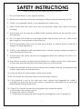
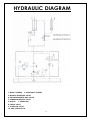
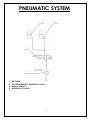
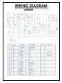
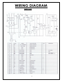
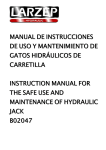
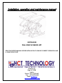
Installation, operation and maintenance manual
HCT3LX30
FULL RISE SCISSOR LIFT
READ THIS ENTIRE MANUAL BEFORE INSTALLATION TO ENSURE CORRECT OPERATION AND
A LONG SERVICE LIFE
2 Tiraines str.
Riga, LV 1058
Latvia
Phone: +371 67702 665
Fax: +371 67702 664
Email: [email protected]
www.hcttechnology.com
TABLE OF CONTENT
USER’S RECORD
3
RECORD OF INSTALLATION
4
SAFETY INSTRUCTIONS
5
INTRODUCTION
6
WARNING SIGNS
7
INSTALLATION
8-9
OPERATION
10
MAINTENANCE
11
OVERALL SIZE
12
SPACE REQUIRED
13
HYDRAULIC DIAGRAM
14
HYDRAULIC CONNECTION
15
PNEUMATIC DIAGRAM
16
WIRING DIAGRAM
17-18
2
USER’S RECORD
RECORD BELOW INFORMATION WHICH LOCATED ON THE NAME
PLATE.
ITEM NO ______________________________
SERIES NO____________________________
DATE OF MFG _________________________
The here blow listed persons have been qualified to use the machine
after installation. The course for use and maintenance has been carried
out by a qualified technician.
1.
2.
3.
4.
………
3
RECORD OF INSTALLATION
MODEL NO ____________________________
SERIES NO ____________________________
CUSTOMER ____________________________
DATE OF INSTALLATION _________________
WE HEREBY DECLARED THAT THE ABOVE MENTIONED MACHINE
HAS BEEN INSTALLED CORRECTLY. ALL FUNCTIONS HAVE BEEN
CHECKED AS WELL AS CORRECT OPERATING OF ALL SAFETY
DEVICES.
WE CONSIDER THEREFORE THE MACHINE WORK IN GOOD
CONDITIONS IN ALL RESPECTS.
Date of Installation
The authorized technician
-----------------------------
------------------------------------
The customer
---------------------------------
4
SAFETY INSTRUCTIONS
( READ THE INSTRUCTIONS ENTIRELY BEFORE OPERATING)
1. Do not install the lift on any asphalt surface
2. Read and understand all safety warning procedures before operating the lift.
3. The lift, in its standard version, is not designed for outdoor use.
4. Keep hands and feet away from any moving parts. Keep feet clear of lift when
lowering.
5. The lift may only be used by qualified staff, properly trained for the specific use of
the machine.
6. Do not wear unfit clothes such as large clothes with flounces, tires, etc, which could
get caught by moving parts of the machine.
7. The lift surrounding area must be free from people or objects which could be a
danger for lifting operations.
8. The lift is only designed to lift the entire body of vehicle, having maximum weight not
more than the lift capacity.
9. Always insure the safety devices are engaged before any attempt to work on or
near vehicle.
10. The vehicle must be centered and positioned in a stable correct way with respect
to the posts and following the instructions given by manufacturer.
11. Make sure that the machine and its devices are working correctly, according to the
specific instructions for maintenance.
12. Lower the lift to its lowest position when service finish.
13. Do not modify the machine without manufacturer’s advice.
14. If the machine is not to be used any more, owners are suggested to make it
unusable by removing the power supply connections, emptying the oil tank and
disposing the liquids by right way.
15. If the lift is to be left unused for a long period, proceed as follows:
a. Disconnect the energy source;
b. Empty the control unit tank.
c. Grease the moving parts which might be damaged by dust or drying out.
5
INTRODUCTION
This guide has been made in order to supply the owner as well the user with the basic instructions for a correct installation,
operation and maintenance of the lift.
Read this guide carefully before using the machine and follow the instructions given by this guide carefully to grant the
machine a correct function, efficiency and a long service life.
INTENDED USE
The lift has been designed and constructed for lifting vehicles with the sole purpose of performing service, repairing and
inspection. Any other use not described is to be considered as improper and irrational, and thus it will be under the whole
responsibility of the operator.
The full rise scissor lift is suitable for lifting motor vehicles having maximum total weight of 3000kg/6600 Pounds .
This appliance must be only used for the purpose of which it is expressly designed. It is forbidden to lift people or others not
specified in this manual. Any other use is to be considered improper and irrational and thus highly forbidden.
The constructor cannot be held responsibilities for any damage or injuries caused by an improper use or by the
non-observance of the following instructions:
The lift, in its standard version, is not intended for outdoor use, in this case, it is necessary to ask the constructor for a
special version.
SAFETY SYSTEM
Besides the reliable hydraulic system, this scissor lift also has
a strong safety locking system as showing left.
The safety teeth will automatically engaged when raising.
But, ensures to press teeth engaged button to lower the
whole machine until teeth engaged, then go under
the vehicle.
TECHNICAL DATA
Lifting height
1820 mm after installation.
Lifting capacity
3000kg
Lifting time
50S
Power supply
220V, single phase
380V, three phase
(Please see nameplate before connecting)
6
WARNING SIGNS
All safety warning signs presented on the machine with the purpose to draw the operator’s attention from dangerous or
unsafe situations. The labels must be kept clean and they have to be replaced if detached or damaged. Read the meaning of
the labels carefully and memorize it.
Warning 1
Warning 6
Warning 11
Warning 2
Warning 7
Warning 3
Warning 4
Warning 8
Warning 12
Warning 5
Warning 9
Warning 13
Warning 10
Warning 14
Warning 1
It is not allowed to stay under the being serviced vehicle during operation.
Warning 2
Operator and standby should not stay too close to the machine, but in the safety place.
Warning 3
When the lift lowers, no auxiliary stand or wooden stick is allowed to use.
Warning 4
Do not shake the vehicle hard, when it still lays on the lift runways.
Warning 5
Only trained technician is permitted to operate the lift.
Warning 6
Take care of your feet when the equipment lifts and lowers.
Warning 7
It is not allowed to lift or lower just one side track.
Warning 8
Do not change safety system of the lift.
Warning 9
Take notice of you feet when the lift lowers.
Warning 10
Ensure the lifting weight balanced on two runways to avoid tilting and sliding.
Warning 11
Keep clean in equipment groove.
Warning 12
Please read carefully the operation manual before use the machine.
Warning 13
Keep the being serviced car parallel with the lifting runways
Warning 14
High voltage in control box.
7
INSTALLATION
BEFORE INSTALLATION
1.
Identify the components and check for shortages. Contact us immediately if shortage discovered.
2.
Installation, adjusting and testing operations are to be performed by qualified staff only.
3.
The lift must be installed on a level concrete floor, having minimum thickness of 15cm and an extension of at
least 1.5m from anchoring points.
4.
The lift installation concrete surface must be relatively smoothes, leveled in all directions
5.
After unloading the lift, place it near the intended installation location.
Remove the shipping brands and packing materials from the unit.
Remove the packing brackets and bolts holding the two columns together.
SPACE REQUIRED
Prepare ground base according to the SPACE REQUIREMENT DRAWING.
The concrete’s thickness should be ≥150mm and the error of levelness should be ≤5mm when the ground condition is
good.
AIR SOURCE REQUIRED
The air compressor network must be preset by user and it must be equipped with a pressure regulator and a
lubricator with pressure between 8 and 10 bar.
ELECTRICAL SYSTEM
Any work on the electrics must be carried out by qualified personnel only.
Equip the electric system of installation place with effective ground circuit.
The electric system adjusting must be made in accordance with the nameplate showing.
CONNECTING
You may start to connect oil hose, air supply and power after the above preparations.
1. OIL HOSE CONNECTING
See the hydraulic diagram for oil hose connecting. Make sure that no soil or other dirty things into the pipe.
2. POWER AND AIR CONNECTION
Connect power line according to the electric diagram
Thee black lines are phase wire, and blue line is N wire. Yellow and green line is for grounding. Connect air hose
(Ф10×Ф7mm) (provided by user) with the air inlet hole of the oil spray.
3. REFILL THE TANK
Pour 16 litres of L-HM32 anti-wear hydraulic oil (provided by user) into oil tank. The highest level should be 10mm from
the top of the tank and the lowest level should be 40mm from the top of the tank (check with the detective ruler on
the oil pouring air cover).
8
4. SYNCHRONIZING
Connecting with power supply, the indicator is on.
Press UP button, checking running of motor. Make sure that the rotating of motor is anticlockwise, if not, cut off
power source then change the inlet orders.
If the motor works in right way, commissioning follows.
Turn on the synchronizing valve C, press up button unit two platforms reach the top limit.
Press DOWN button to lower the platforms to the complete bottom.
Try the above operation twice.
Turn off the valve.
Now, the lift is in normal working status and two platforms should be synchronized well.
5. BASE FRAME FIXED.
Fix the frame with expansion bolt.
6. LOADING TEST
Never try to use the lift with vehicle on without testing fistly.
This step is very important to check if there is any leakage of hydraulic line connectors or air hose. Also make sure the
base frame is fixed well.
If there’s no abnormal noise or leakage after running two or three times, Run with load never exceeding 3000kg at a
low height.
Then raise higher gradually.
If two platforms are not level, do the operation as in SYNCHRONIZING
9
OPERATION
WARNING: DO NOT PLACE ANY VEHICLE ON THE LIFT BEFORE TRIAL OPERATION. RAISE THE LIFT UP
AND DOWN SEVERAL TIMES TO INSURE LATCHES CLICK TOGETHER AND AIR EXHAUSTED FROM THE
CYLINDERS.
BEFORE OPERATION
a. Check all the pipelines and joints before use. The machine only can be used after there is not any leakage.
b. The lift, if its safety device malfunctions, shall not be used.
c. The machine shall not raise or lower an automobile if the center of gravity of automobile is not within the
supporting range of the supporting device. Otherwise, the manufacturer will not bear any responsibility for
the consequence resulted from the operation above mentioned.
d. The staff or operators shall be in a safe position when the machine raise or lower.
e. When the lift with vehicle on reaches a desired height, first of all, the main switch must be turned off before
the automobile is repaired so as to prevent non-operator or unauthorized person from pressing the start
switch.
f. Always press teeth engaged button to make the locking teeth engaged, then go under the vehicle.
Never allow anyone to go under the lift when raising or lowering.
INSTRUCTIONS FOR USE
RAISING THE LIFT
1.
Make sure that you have read the operation
manual before operation.
2.
Always lift the vehicle at the manufacturer
recommended points.
3.
Position the vehicle right on the center of two platforms.
4.
Raise the lift by pressing the push button on
control box until the pads touch firmly the
right points and recheck if the vehicle is
secure.
5.
Check the security of vehicle, then perform maintenance or
6.
Press safety lock to make safety teeth engaged, then work under the vehicle.
repair work.
LOWERING THE LIFT
1.
Press down button to lower the lift.
2.
The control unit will give alarming when the lift lowered to about 800mm to ground.
3.
Press button DOWN II to continue lowering, until reaching complete bottom.
10
MAINTENANCE
Ever-Eternal will give the user one-year warranty of quality for the machine. If something wrong with the machine
within the term of service, we will repair or replace the product according to the user’s demand. The manufacturer
will not take any responsibility for improper installation and operation, overload running, wrong concrete ground
(that can not meet the requirements in the manual), normal mechanical abrasion and insufficient maintenance. The
warranty will be carried out on the basis of the type and serial number of the equipment. Therefore, the users shall
provide them to the manufacturer without fail.
The several pieces of maintenance operations to be carried out are described below. A low operating cost and a
long life of the machine are from routine observation of there operations.
The listed intervention times are given for information and they refer to normal operating conditions. They can
change according to the kind of service, environment, frequency of use, etc.
1.
DAILY PRE-OPERATION CHECK
The user should perform daily check. Daily check of safety latch system is very important – the discovery of
device failure before needed could save you from expensive property damage, lost production time,
serious personal injury, even death.
. Check safety lock audibly and visually while in operation
. Check hydraulic connections, and hoses for leakage.
. Check chain connections, cable connections, wiring and switch for damage.
. Check bolts, nut and screws and tighten.
. Check swing arm restraints.
2. WEEKLY MAINTENANCE
. Check the cleanness of the mobile parts.
. Check the safety device as previously described.
. Check hydraulic fluid level as follow: let the trolleys go up completely and in case they do not reach
maximum height, add oil.
Check and tighten bolts, nuts and screws.
3. MONTHLY MAINTENANCE
. Check the tightening of screws
. Check the hydraulic system seal and tighten the loose unions, if necessary.
. Check the greasing and wear condition of pins, rollers, bushes, of trolley structure as well as arms and
relevant extensions, if necessary, replace the damaged parts by original spare parts.
4. YEARLY MAINTENANCE
. Empty the tank and check the conditions of the hydraulic fluid. Clear the oil filter.
If the above maintenance operations are carried out, there will be an advantage for the user,
who will find the equipment in perfect condition each time he restarts work.
11
OVERALL DIAGRAM
12
SPACE REQUIRED
13
HYDRAULIC DIAGRAM
1. MAIN CYLINDER
2. ASSISTANT CYLINDER
3. MANUAL REVERSING VALVE
4. ELECTROMAGNETIC BALL VALVE
5. LOWERING THROTTLE VALVE
6. MOTOR
7. GEAR PUMP
8. CHECK VALVE
9. OVERFLOW VALVE
10. ANTI-SURGE VALVE
14
HYDRAULIC CONNECTION
15
PNEUMATIC SYSTEM
1.
2.
3.
4.
AIR FILTER
ELECTROMAGNETIC REVERSING VALVE
MAIN CYLINDER
ASSISTANT CYLINDER
16
WIRING DIAGRAM
SINGLE PHASE
17
WIRING DIAGRAM
THREE PHASE
18
We’ve tried to do our very best to provide complete and detailed information so that your installation and operation
experience is free of problems. But, please feel free to contact us, if you should run into any problems in installation and
operation your new lift, or have questions on some of the parts.
19