1
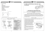
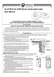
Pool and Spa Systems.
Pool and Spa Systems.
A. Place the light in front of you so that the captive screw hole is at the top, and the lamp is in a horizontal
position.
b. Grasp the lamp to the right, compressing the spring in the lamp socket, until the left side of the lamp comes
free the fixed socket end.
WARNING
Be sure power is OFF before installing or removing lamp. Allow lamp to cool before relamping. This light
fixture uses a Halogen Quartz lamp. Do Not touch lamp with bare hands, this may severely reduce its life. Use
the plastic furnished with the replacement lamp to eliminate finger prints from getting on lamp.
UL-NS75 & UL-NS150 Stainless Steel
Underwater Light Operating Instruction
8. Install the new lamp by performing steps II. 1 through 7 in reverse order.
NOTE: Select proper lamp for either 12 volt applications.
9. Never reuse the old lens seal when reassembling any light. Replace with a genuine Underwater Light lens
seal.
10. Install the lens seal, lens and plastic face ring, The lens must be placed with the word "TOP" to the top of the
housing.
WARNING
Always install a new lens seal, whenever disassembling the light. Failure to do so may permit water to leak
into the assembly which could cause; (a) an electrical hazard resulting in death or serious injury to pool
users, installer, or others due to electrical shock, or (b) breakage of the lamp or lens, which likewise could
result in serious injury to pool user, installers, or bystanders, or in damage to property.
J-BOX
FINISHED SURFACE
1
Concrete Replacement Parts
Item
Description
Wall Bracket
1
Captive Screw
2
Light Fixture
3
Mounting O ring
4
Mounting Bracket
,
4
2
Figure 3
Item
1
2
3
4
5
6
7
8
9
10
11
12
13
14
3
Underwater Light Replacement Parts
Part
Description
Number
01051169
01041037
02021027
04011005
89043704
03011016
89043701
03011151
02021036
03011149
01051171
02011158
89043702
04014016
Item
1
2
3
4
5
6
7
8
9
10
11
12
13
14
Face ring
Lens
Lens seal
Lamp 12 volt/75watt
UL-NS75W Face Plate
Screw on face
Nut on cable
Screw
O'ring Seal For Cover
Mounting screw
Mounting Bracket
Gasket
Wall Bracket
Cable
Figure 4
Underwater Light Replacement Parts
Part
Description
Number
01051170
87012008
02021029
04011005
89043703
03011016
89043701
03011151
02021028
03011149
01051172
02011158
89043702
04013004
Face ring
Lens
Lens seal
Lamp 12 volt/75watt
UL-NS150W Face Plate
Screw on face
Nut on cable
Screw
O'ring Seal For Cover
Mounting screw
Mounting Bracket
Gasket
Wall Bracket
Cable
PLEASE READ THE FOLLOWING CAREFULLY AND
KEEP THIS USER MANUAL SAVE FOR FUTURE REFERENCE
DANGER !
RISK OF ELECTRICAL SHOCK OR ELECTROCUTION
This underwater light fixture must be installed by a licensed or certified electrician or a qualified serviceman
in accordance to the requirements of your government standard or local authorities. Improper installation will
create electric hazards which could result in serious injury, death as well as damage to the property. Before
servicing the light,disconnect the power supply from the circuit breaker.Failure to do so could result in serious
injury, death and or damage to the property.
EMLI08062007
4-4
1-4
Pool and Spa Systems.
Pool and Spa Systems.
I. Installing a mounting bracket and light fixture during new vinyl pool construction:
A. Preparatory steps which must be completed by the electrician before light is installed,
see Figure 1.
120CM MIN.
TO GFCI. CIRCUIT
BREAKER AND
POWER SOURCE
30.5CM MIN. FROM BOTTOM OF
JUNCTION BOX OR LOW VOL TAGE
TRANSFORMER TO WATER LINE
45.5CM MIN. FROM WATER LINE
TO TOP OF LENS
2.5 CM RIGID CONDUIT
2. If pool surface is to be plastered, you must allow proper concrete cutback for plaster thickens.
3. Wrap a length of the cord up to a maximum of 240CM long on the back of the light assembly. Wind a
minimum of three (3) wraps of cord so that the last wrap stops at the top of the light. This extra cord
allows you to bring the light out of the pool for revamping and serving.
NOTE: Leave 2 to 3 of slack cord at the top so that the light may be tipped back for removal.
4. Feed the remaining cord through the conduit hole in the mounting hub.
5. Place light clip over pin on the bottom of the light mounting bracket and press lightly to secure into
place. Secure at top with captive screw. When installed properly, the housing spacer should fill any gap
between the pool wall and the light.
6. Connect cord to electrical wires at Junction Box, be careful not to pull the 7.5CM of slack cord at the
back of the light through the conduit when
connecting the wires. All wiring should be
DO NOT MOUNT ON:
DO MOUNT ON:
connected to a Class A GFCI in accordance
with electrical codes.
7. Connect all three wires to the corresponding
circuit wires in the junction box and secure
the junction box cover in place.
8. Before operating the light for more then 10
seconds fill pool Underwater Light is
REVERSE RADIUS
IRREGULAR OR
FLAT
WALLS WITH NO TIGHTER
completely submerged in water. To check
SURFACE
UNEVEN SURFACES
SURFACE
THAN 6 FT. RADIUS AS
VIEWED FROM TOP
for proper operation turn on main switch or
Figure 2
circuit breaker, as well as the switch which
operates Underwater light itself.
X
PILOT SCREW AT TOP
CONCRETE MUST BE CUT BACK
AROUND NICHE TO ALLOW FOR
A COMPACT PLASTER SEAL
WARNING
Figure 1.
1. Ensure that the electrical system of the pool conforms with the requirements of the current National Electrical
Code (NEC) and all local codes and ordinances. A licensed or certified electrician must install the electrical
system to meet or exceed those requirements before the Underwater light is installed. Some of the
requirements of the NEC are listed below.
a. The lighting circuit must have a Ground Fault Circuit Interrupter (GFCI), and have an appropriately rated
circuit breaker.
b. The junction box, or the low voltage transformer for 12 volt models, is located at least 30.5CM above
water level and at least 120CM from the edge of the pool, see Figure 1.
c. The light fixture and metal items within 150CM of the pool must be properly electrically bonded.
d. The mounting bracket must be properly installed so that the top edge of the Underwater Light's lens is at
least 45.5CM below the surface of the water in the pool. Top of lens corresponds to center of center of
Plastic Mounting Hub. see Figure 1.
e. The mounting bracket must be properly electrically bonded and grounded via the NO. 8AWG ground
connector located at the upper left corner of the mounting bracket.
2. Consult the local Government Building Department to be certain that the pool's electrical system meets
all applicable requirements.
B. Perform the following steps after the electrical system requirements are met. See Figure 3.
1. Locate position on a vertical wall where light is to be installed. The top of the light lens must be 45.5CM
below normal water level, as required by NEC Article 680. The center of the mounting hub will line with the
top of light lens. See Figure 2.
2-4
Never operate this Underwater Light for more than 10 seconds unless it is totally submerged in water. Without
total submersion, the light assembly will get extremely hot, which may result in serious injury to pool users,
installers, or bystanders, or in damage to property.
WARNING
Use only the special stainless steel pilot screw provided with Underwater Light. Failure to use the screw
provided could create an electrical hazard which could result in death or serious injury to pool users, installers
or others due to electrical shock.
C. Winterizing: Light should be left in place for winterization.
II. Replacing a lamp only:
DANGER
Always disconnect power to the pool light at the circuit breaker before servicing the light. Failure to do so could
result in death or serious injury to installer, servicemen, pool users, or others due to electrical shock.
A. The following steps may be performed by a qualified pool serviceman or homeowner. See Figure 4.
1. Turn off main electrical switch or circuit breaker as well as the switch which operates Underwater Light itself.
2. Unscrew the captive screw on the top of the light, then tilt the top of the light out form the wall and lift the
bottom of the light out of the bracket. Unwind the excess cable that is stored in the back of the light.
3. Place the light face down on the deck. Be careful not to scratch the lens.
4. Remove the housing spacer from the back of the light.
5. With a Phillips head screwdriver, remove the 10 screws on the back of the light.
6. Turn the light over while holding the glass lens, remove the glass lens, plastic ring and lens seal.
7. To remove the lamp:
3-4