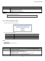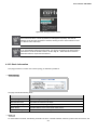
1
User’s Manual: SW-24400
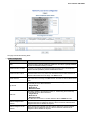
User’s Manual
SW-24400
24-Port PoE Managed Stackable Switch
1
User’s Manual: SW-24400
Trademarks
Copyright © i3 International Inc. 2013.
Contents subject to revision without prior notice.
All other trademarks belong to their respective owners.
Disclaimer
i3 International does not warrant that the hardware will work properly in all environments and applications, and makes no warranty and
representation, either implied or expressed, with respect to the quality, performance, merchantability, or fitness for a particular purpose.
i3 International has made every effort to ensure that this User's Manual is accurate; i3 International disclaims liability for any
inaccuracies or omissions that may have occurred.
Information in this User's Manual is subject to change without notice and does not represent a commitment on the part of i3
International. i3 International assumes no responsibility for any inaccuracies that may be contained in this User's Manual. i3
International makes no commitment to update or keep current the information in this User's Manual, and reserves the right to make
improvements to this User's Manual and/or to the products described in this User's Manual, at any time without notice.
If you find information in this manual that is incorrect, misleading, or incomplete, we would appreciate your comments and suggestions.
FCC Warning
This equipment has been tested and found to comply with the limits for a Class A digital device, pursuant to Part 15 of the FCC Rules.
These limits are designed to provide reasonable protection against harmful interference when the equipment is operated in a
commercial environment. This equipment generates, uses, and can radiate radio frequency energy and, if not installed and used in
accordance with the Instruction manual, may cause harmful interference to radio communications. Operation of this equipment in a
residential area is likely to cause harmful interference in which case the user will be required to correct the interference at whose own
expense.
CE Mark Warning
This is a Class A product. In a domestic environment, this product may cause radio interference, in which case the user may be
required to take adequate measures.
Energy Saving Note of the Device
This power required device does not support Standby mode operation.
For energy saving, remove the power cable to disconnect the device from the power circuit.
Without removing power cable, the device will still consume power from the power source. In the view of Saving the Energy and reduce
the unnecessary power consuming, it is strongly suggested to remove the power connection for the device if this device is not intended
to be active.
WEEE Warning
To avoid the potential effects on the environment and human health as a result of the presence of hazardous
substances in electrical and electronic equipment, end users of electrical and electronic equipment should
understand the meaning of the crossed-out wheeled bin symbol. Do not dispose of WEEE as unsorted municipal
waste and have to collect such WEEE separately.
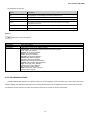
Revision
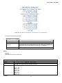
i3 International 24-Port 10/100/1000Mbps with 4 Shared SFP / 24 100/1000 SFP Slots with 8 Shared TP Managed Stackable Switch
User's Manual
FOR MODELS: SW-24400
REVISION: 1.2
2
User’s Manual: SW-24400
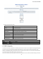
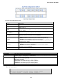
1. INTRODUCTION ................................................................................................................. 10
1.1 Package Contents ............................................................................................................................................... 10
1.2 Product Features and Specification .................................................................................................................. 10
2. INSTALLATION ................................................................................................................... 13
2.1 Hardware Description ......................................................................................................................................... 13
2.1.1 Switch Front Panel ................................................................................................................................................ 13
2.1.2 LED Indicators ....................................................................................................................................................... 13
2.1.3 Switch Rear Panel ................................................................................................................................................. 15
2.2 Installation and Connection ............................................................................................................................... 15
2.2.1 Desktop Installation ............................................................................................................................................... 15
2.2.2 Rack Mounting ...................................................................................................................................................... 16
2.2.3 Installing the SFP transceiver ................................................................................................................................ 17
2.3 Stack Installation ................................................................................................................................................. 19
2.3.1 Connecting Stacking cables .................................................................................................................................. 19
2.3.2 Management Stacking ........................................................................................................................................... 20
3. SWITCH MANAGEMENT .................................................................................................... 22
3.1 Network and System Requirements .................................................................................................................. 22
3.2 Management Access Overview .......................................................................................................................... 22
3.2.1 Administration Console .......................................................................................................................................... 22
3.2.2 Command Line Interface ....................................................................................................................................... 25
3.2.2.1. Telnet Login.............................................................................................................................................. 26
3.2.3. Web Management ................................................................................................................................................ 27
3.2.3.1. Main Web Page ....................................................................................................................................... 28
3.2.4. SNMP-Based Network Management .................................................................................................................... 29
3.3 Using this Manual ................................................................................................................................................ 30
4. CONFIGURATION ............................................................................................................... 31
4.1 System .................................................................................................................................................................. 31
4.1.1 System Information ............................................................................................................................................... 31
4.1.2 IP Configuration ..................................................................................................................................................... 34
4.1.3 IPv6 Configuration ................................................................................................................................................. 35
4.1.4 Users Configuration ............................................................................................................................................... 35
4.1.5 Users Privilege Levels ........................................................................................................................................... 37
3
User’s Manual: SW-24400
4.1.6 NTP Configuration ................................................................................................................................................. 39
4.1.7 UPnP Configuration ............................................................................................................................................... 40
4.1.8 DHCP Relay .......................................................................................................................................................... 41
4.1.9 DHCP Relay Statistics ........................................................................................................................................... 44
4.1.10 CPU Load ............................................................................................................................................................ 45
4.1.11 System Log .......................................................................................................................................................... 46
4.1.12 Detailed Log ........................................................................................................................................................ 47
4.1.13 Remote Syslog .................................................................................................................................................... 48
4.1.14 SMTP Configure .................................................................................................................................................. 48
4.1.15 Web Firmware Upgrade ...................................................................................................................................... 50
4.1.16 TFTP Firmware Upgrade ..................................................................................................................................... 51
4.1.17 Configuration Backup .......................................................................................................................................... 51
4.1.18 Configuration Upload ........................................................................................................................................... 52
4.1.19 Factory Default .................................................................................................................................................... 53
4.1.20 System Reboot .................................................................................................................................................... 53
4.2 Simple Network Management Protocol ............................................................................................................. 53
4.2.1 SNMP Overview .................................................................................................................................................... 53
4.2.2 SNMP System Configuration ................................................................................................................................. 54
4.2.3 SNMP System Information Configuration .............................................................................................................. 57
4.2.4 SNMP Trap Configuration ...................................................................................................................................... 57
4.2.5 SNMPv3 Configuration .......................................................................................................................................... 61
4.2.5.1 Communities Configuration ....................................................................................................................... 61
4.2.5.2 Users Configuration .................................................................................................................................. 62
4.2.5.3 Groups Configuration ................................................................................................................................ 64
4.2.5.4 Views Configuration .................................................................................................................................. 66
4.2.5.5 SNMPv3 Accesses Configuration ............................................................................................................. 66
4.3 Port Management ................................................................................................................................................ 69
4.3.1 Port Configuration ................................................................................................................................................. 69
4.3.2 Port Statistics Overview ......................................................................................................................................... 72
4.3.3 Port Statistics Detail............................................................................................................................................... 73
4.3.4 SFP Module Information ........................................................................................................................................ 75
4.3.5 Port Mirroring Configuration .................................................................................................................................. 76
4.4 Link Aggregation ................................................................................................................................................. 78
4.4.1 Static Aggregation Configuration ........................................................................................................................... 79
4.4.2 LACP Configuration ............................................................................................................................................... 81
4.4.3 LACP System/Port Status ...................................................................................................................................... 84
4.4.4 LACP Port Statistics .............................................................................................................................................. 85
4.5 VLAN ..................................................................................................................................................................... 86
4
User’s Manual: SW-24400
4.5.1 VLAN Overview ..................................................................................................................................................... 86
4.5.2 IEEE 802.1Q VLAN ............................................................................................................................................... 87
4.5.3 VLAN Basic Information ........................................................................................................................................ 88
4.5.4 VLAN Port Configuration ....................................................................................................................................... 89
4.5.5 VLAN Membership Configuration .......................................................................................................................... 92
4.5.6 VLAN Membership Status for User Static .............................................................................................................. 94
4.5.7 VLAN Port Status .................................................................................................................................................. 94
4.5.8 Private VLAN Membership Configuration .............................................................................................................. 96
4.5.9 Port Isolation Configuration ................................................................................................................................... 98
4.6 Spanning Tree Protocol ...................................................................................................................................... 99
4.6.1 Theory ................................................................................................................................................................... 99
4.6.2 STP Bridge Configuration .................................................................................................................................... 101
4.6.3 Bridge Status ....................................................................................................................................................... 104
4.7.4 CIST Port Configuration ...................................................................................................................................... 104
4.6.5 MSTI Priorities ..................................................................................................................................................... 108
4.6.6 MSTI Configuration ............................................................................................................................................. 109
4.6.7 MSTI Ports Configuration ..................................................................................................................................... 111
4.6.8 Port Status ............................................................................................................................................................114
4.6.9 Port Statistics ........................................................................................................................................................115
4.7 Multicast ............................................................................................................................................................. 116
4.7.1 IGMP Snooping ....................................................................................................................................................116
4.7.2 IGMP Snooping Configuration ..............................................................................................................................116
4.7.3 IGMP Port Related Configuration .........................................................................................................................118
4.7.4 IGMP Snooping VLAN Configuration....................................................................................................................119
4.7.5 Port Group Filtering ............................................................................................................................................. 120
4.7.6 IGMP Snooping Status ........................................................................................................................................ 121
4.7.7 MVR Configuration .............................................................................................................................................. 122
4.7.8 MVR Status ......................................................................................................................................................... 125
4.8 Quality of Service .............................................................................................................................................. 126
4.8.1 QCL Configuration Wizard ................................................................................................................................... 126
4.8.1.1 Set up Policy Rules ................................................................................................................................. 127
4.8.1.2 Network Application Rules ...................................................................................................................... 128
4.8.1.3 ToS Precedence Mapping ....................................................................................................................... 130
4.8.1.4 Set up VLAN Tag Priority Mapping .......................................................................................................... 131
4.8.2 QoS Control List Configuration ............................................................................................................................ 132
4.8.2.1 QoS Control Entry Configuration............................................................................................................. 134
4.8.3 Port QoS Configuration ....................................................................................................................................... 135
4.8.4 Bandwidth Control ............................................................................................................................................... 137
5
User’s Manual: SW-24400
4.8.5 Storm Control Configuration ................................................................................................................................ 138
4.8.6 QoS Statistics ...................................................................................................................................................... 140
4.8.7 DSCP Remarking ................................................................................................................................................ 140
4.8.8 Voice VLAN Configuration ................................................................................................................................... 142
4.8.9 Voice VLAN OUI Table ........................................................................................................................................ 144
4.9 Access Control Lists ......................................................................................................................................... 146
4.9.1 Access Control List Status ................................................................................................................................... 146
4.9.2 Access Control List Configuration ........................................................................................................................ 147
4.9.3 ACE Configuration ............................................................................................................................................... 150
4.9.4 ACL Ports Configuration ...................................................................................................................................... 155
4.9.5 ACL Rate Limiter Configuration ........................................................................................................................... 157
4.10 Authentication.................................................................................................................................................. 158
4.10.1 Authentication Configuration.............................................................................................................................. 158
4.10.2 Network Access Server Configuration ............................................................................................................... 159
4.10.3 Network Access Overview ................................................................................................................................. 166
4.10.4 Network Access Statistics .................................................................................................................................. 167
4.10.5 Authentication Server Configuration .................................................................................................................. 171
4.10.6 RADIUS Overview ............................................................................................................................................. 172
4.10.7 RADIUS Details ................................................................................................................................................. 175
4.11 Security ............................................................................................................................................................. 179
4.11.1 Port Limit Control ............................................................................................................................................... 179
4.11.2 Access Management ......................................................................................................................................... 183
4.11.3 Access Management Statistics .......................................................................................................................... 185
4.11.4 HTTPs ............................................................................................................................................................... 186
4.11.5 SSH ................................................................................................................................................................... 187
4.11.6 Port Security Status ........................................................................................................................................... 188
4.11.7 Port Security Detail ............................................................................................................................................ 190
4.11.8 DHCP Snooping ................................................................................................................................................ 191
4.11.9 DHCP Snooping Statistics ................................................................................................................................. 192
4.11.10 IP Source Guard Configuration ........................................................................................................................ 194
4.11.11 IP Source Guard Static Table ........................................................................................................................... 196
4.11.12 ARP Inspection ................................................................................................................................................ 197
4.11.13 ARP Inspection Static Table ............................................................................................................................. 198
4.12 Address Table .................................................................................................................................................. 199
4.12.1 MAC Address Table Configuration ..................................................................................................................... 200
4.12.2 Static MAC Table Configuration ......................................................................................................................... 201
4.12.3 MAC Address Table Status ................................................................................................................................ 202
4.12.4 MAC Table Learning .......................................................................................................................................... 205
6
User’s Manual: SW-24400
4.12.5 Dynamic ARP Inspection Table.......................................................................................................................... 206
4.12.6 Dynamic IP Source Guard Table ....................................................................................................................... 207
4.13 LLDP ................................................................................................................................................................. 208
4.13.1 Link Layer Discovery Protocol ........................................................................................................................... 208
4.13.2 LLDP Configuration ........................................................................................................................................... 208
4.13.3 LLDPMED Configuration ................................................................................................................................... 212
4.13.4 LLDP-MED Neighbour ....................................................................................................................................... 217
4.13.5 Neighbour .......................................................................................................................................................... 219
4.13.6 Port Statistics ..................................................................................................................................................... 220
4.14 Network Diagnostics ....................................................................................................................................... 221
4.14.1 Ping ................................................................................................................................................................... 222
4.14.2 IPv6 Ping ........................................................................................................................................................... 223
4.14.3 Remote IP Ping Test .......................................................................................................................................... 224
4.14.4 Cable Diagnostics ............................................................................................................................................. 224
4.15 Power over Ethernet........................................................................................................................................ 225
4.15.1 Power Configuration .......................................................................................................................................... 226
4.15.2 Port Configuration ............................................................................................................................................. 229
4.15.3 PoE Status......................................................................................................................................................... 231
4.15.4 PoE Schedule .................................................................................................................................................... 233
4.15.5 LLDP Neighbour Power Over Ethernet.............................................................................................................. 233
4.16 Stack ................................................................................................................................................................. 234
4.16.1 Stacking Architecture ......................................................................................................................................... 236
4.16.1.1 Switch IDs ............................................................................................................................................. 236
4.16.1.2 Master Election ..................................................................................................................................... 237
4.16.1.3 Stack Redundancy ................................................................................................................................ 237
4.16.1.4 Shortest Path Forwarding ..................................................................................................................... 238
4.16.2 Stack Configuration ........................................................................................................................................... 239
4.16.3 Stack Information ............................................................................................................................................... 241
4.16.4 Stack Port State Overview ................................................................................................................................. 242
5. ADDITIONAL CONSOLE COMMANDS ............................................................................ 244
6. TROUBLESHOOTING....................................................................................................... 245
APPENDIX A. SWITCH FEATURE OPERATION ................................................................. 246
A.1 Address Table and Learning ............................................................................................................................ 246
A.2 Forwarding and Filtering .................................................................................................................................. 246
A.3 Store-and-Forward ............................................................................................................................................ 246
7
User’s Manual: SW-24400
A.4 Auto-Negotiation ............................................................................................................................................... 247
APPENDIX B. POWER OVER ETHERNET OVERVIEW ...................................................... 248
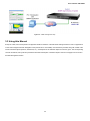
B.1. PoE Introduction .............................................................................................................................................. 248
B.2. PoE System Architecture ................................................................................................................................ 248
B.2.1. Power Transference through a CAT5 Ethernet cable ......................................................................................... 248
B.3. PoE Provisioning Process .............................................................................................................................. 249
B.3.1. Line Detection .................................................................................................................................................... 249
B.3.2. Classification ...................................................................................................................................................... 250
B.3.3. Start-up .............................................................................................................................................................. 250
B.3.4. Operation ........................................................................................................................................................... 250
B.3.5. Power Overloads ............................................................................................................................................... 250
APPENDEX C: ETHERNET STANDARDS ........................................................................... 251
C.1 Switch's RJ-45 Pin Assignments..................................................................................................................... 251
C.2 10/100Mbps, 10/100Base-TX ............................................................................................................................ 251
APPENDEX D: GLOSSARY ................................................................................................. 253
8
User’s Manual: SW-24400
9
User’s Manual: SW-24400
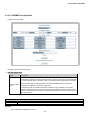
1. INTRODUCTION
The i3 International Layer 2 Managed Gigabit Switch series switches are multiple port Gigabit Ethernet Switches with SFP fibre
optic connective ability and robust layer 2 features; the description of the model discussed in this manual is below.
The term “Managed Switch” refers to the Switch titled on the cover page of this User’s manual.
1.1 Package Contents
The box should contain the following items:
The Managed Switch
User’s manual CD
Quick installation guide
19” Rack mount accessory kit
Power cord
Rubber feet
RS-232 DB9 male Console cable
CB-STX50 – 50cm stack cable
x1
x1
x1
x1
x1
X4
x1
x1
If any of these are missing or damaged, please contact your dealer immediately, if possible, retain the carton including the
original packing material in case of repair/return.
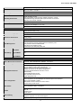
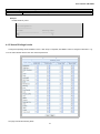
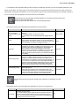
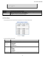
1.2 Product Features and Specification
IMPORTANT NOTE: This PoE network switch is recommended for IP cameras ONLY.
Product
SW-24400
Hardware Specification
Copper Ports
24 10/ 100/1000Base-T RJ-45 Auto-MDI/MDI-X ports
SFP/mini-GBIC Slots
4 SFP interfaces, shared with Port-21 to Port-24
Console Port
1 x RS-232 DB9 serial port (115200, 8, N, 1)
Stacking Ports
2 5GbE / Cross-HDMI interface
Switch Fabric
68Gbps / non-blocking
Address Table
8K entries, automatic source address learning and ageing
Share data Buffer
1392 kilobytes
Switch Processing Scheme
Store-and-Forward
Flow Control
IEEE 802.3x Pause Frame for Full-Duplex
Back pressure for Half-Duplex
Jumbo Frame
10Kbytes
Reset Button
< 5 seconds: System reboot
> 10 seconds: Factory Default
Dimension (W x D x H)
440 x 300 x 44.5 mm, 1U high
Weight
4.5kg
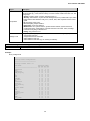
10
User’s Manual: SW-24400
LED
Power, Link/Act and speed per Gigabit port
Power Consumption
Max. 432 watts / 1473 BTU
Power Requirement – AC
AC 100~240V, 50/60Hz
Stacking Numbers
16
Stacking Architecture
Chain and Ring modes
Link Aggregation groups spanning multiple switches in a stack
Hardware learning with MAC table synchronization across stack
Mirroring across stack available
Stacking Bandwidth
10Gbps Full-Duplex
Stack ID Display
7-Segment LED Display (1~9, A~F,0)
ESD Protection
6KV DC
Power over Ethernet
PoE Standard
IEEE 802.3af/at PoE / PSE
PoE Power Supply Type
End-Span
PoE Power Output
Per Port 52V DC. Max. 30.8 watts
Power Pin Assignment
1/2(+), 3/6(-)
PoE Power Budget
360 Watts
PoE Management
Auto detect powered device (PD)
Circuit protection prevent power interference between ports
Per port PoE function enable/disable
PoE Port Power feeding priority
Total and per port PoE port power limit
PoE Ability
Number of PD
@ 7Watts
24
Number of PD
@ 15.4Watts
23
Number of PD
@ 30.8Watts
11
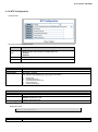
Layer 2 Function
Basic Management Interfaces
Console, Telnet, Web Browser, SNMPv1, v2c and v3
Secure Management Interface
SSH, SSL, SNMP v3
Management Features
Four RMON groups (history, statistics, alarms, and events)
IPv6 IP Address / NTP / DNS management
Built-in Trivial File Transfer Protocol (TFTP) client
BOOTP and DHCP for IP address assignment
Firmware upload/download via HTTP / TFTP
DHCP Relay
User Privilege levels control
NTP (Network Time Protocol)
Cable diagnostic tools
Port configuration
Port disable/enable.
Auto-negotiation 10/100/1000Mbps full and half duplex mode selection.
Flow Control disable / enable.
Bandwidth control on each port, storm control
Power saving mode control
Port Status
Display each port’s speed duplex mode, link status, Flow control status.
Auto negotiation status, trunk status.
VLAN
802.1Q Tagged Based VLAN ,up to 255 VLAN groups
Q-in-Q
Private VLAN
Voice VLAN
Port trunking
IEEE 802.3ad LACP / Static Trunk
Support 12 groups of 16-Port trunk support
QoS
Ingress Shaper and Egress Rate Limit per port bandwidth control
11
User’s Manual: SW-24400
Traffic classification based, Strict priority and WRR
4-level priority classifications:
- Port Number
- 802.1p priority
- DS/TOS field in IP Packet
- Typical network applications
Supports QoS and In/Out bandwidth control on each port
QoS configuration wizard for easy QoS Control List creation
DSCP remarking
IGMP Snooping
IGMP (v1/v2) Snooping, up to 255 multicast Groups
IGMP Querier mode support
Access Control List
IP-Based ACL / MAC-Based ACL
Up to 256 entries
Additional Security Features
Source MAC / IP address binding
DHCP Snooping
Dynamic ARP Inspection
IP Source Guard
Auto DoS
IP address access management
SNMP MIBs
RFC-1213 MIB-II
IF-MIB
RFC-1493 Bridge MIB
RFC-1643 Ethernet MIB
RFC-2863 Interface MIB
RFC-2665 Ether-Like MIB
RFC-2737 Entity MIB
RFC-2618 RADIUS Client MIB
RFC-2933 IGMP-STD-MIB
RFC3411 SNMP-Frameworks-MIB
IEEE 802.1X PAE
LLDP
MAU-MIB
Standards Conformance
Regulation Compliance
FCC Part 15 Class A, CE
Standards Compliance
IEEE 802.3 10Base-T
IEEE 802.3u 100Base-TX/100Base-FX
IEEE 802.3z Gigabit SX/LX
IEEE 802.3ab Gigabit 1000T
IEEE 802.3x Flow Control and Back pressure
IEEE 802.3ad Port trunk with LACP
IEEE 802.1d Spanning tree protocol
IEEE 802.1w Rapid spanning tree protocol
IEEE 802.1s Multiple spanning tree protocol
IEEE 802.1p Class of service
IEEE 802.1Q VLAN Tagging
IEEE 802.1x Port Authentication Network Control
IEEE 802.1ab LLDP
RFC 768 UDP
RFC 793 TFTP
RFC 791 IP
RFC 792 ICMP
RFC 2068 HTTP
RFC 1112 IGMP version 1
RFC 2236 IGMP version 2
IEEE 802.3af Power over Ethernet
IEEE 802.3at Power over Ethernet (Pre-Standard)
12
User’s Manual: SW-24400
2. INSTALLATION
This section describes the hardware features and installation of the Managed Switch to desktop or rack mount. For easier
management and control of the Managed Switch, familiarize yourself with its display indicators and ports. Read this chapter
completely before connecting any network device to the Managed Switch.
IMPORTANT NOTE: This PoE network switch is recommended for IP cameras ONLY.
2.1 Hardware Description
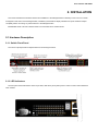
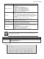
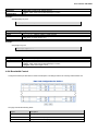
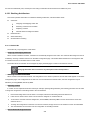
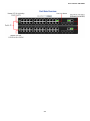
2.1.1 Switch Front Panel
The unit front panel provides a simple interface for monitoring the switch.
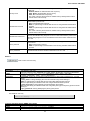
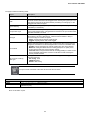
2.1.2 LED Indicators
The front panel LEDs indicates the status of port links, data activity and system power in order to monitor and troubleshoot
when needed.
13
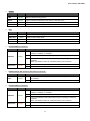
User’s Manual: SW-24400
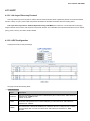
System
LED
Color
Function
PWR
Green
Lights to indicate that the switch is powered on.
Blinks to indicate booting process.
Master
Green
Lights to indicate that the switch is the master of the stack group
STX1
Green
Lights to indicate the stacking link through that port is successfully established.
STX2
Green
Lights to indicate the stacking link through that port is successfully established.
Alert
LED
Green
Lights to indicate power supply failure
FAN1 Alert
Green
Lights to indicate FAN1 failure
FAN2 Alert
Green
Lights to indicate FAN2 failure
FAN3 Alert
Green
Lights to indicate FAN3 failure
10/100/1000Base-T interfaces
LNK/ACT
PoE In-Use
Color
Green
Function
Lights
To indicate the link through that port is successfully established at a rate of
10Mbps or 100Mbps or 1000Mbps
Blink
To indicate that the switch is actively sending or receiving data over that port.
Off
The L10/100 NK/ACT LED indicates that the port is operating at 10Mbps or
100Mbps
When the LNK/ACT LED is off, it indicates that the port is link down
Lights
To indicate the port is providing 48VDC in-line power
Off
To indicate the connected device is not a PoE Powered Device (PD)
Orange
1000Base-SX/LX SFP interfaces (Shared Port-21~Port-24)
LED
LNK
Function
PWR Alert
LED
Color
Color
Function
Lights
To indicate the link through that SFP port is successfully established at a rate
of 1000Mbps
Off
To indicate that the SFP port is link down
Green
10/100/1000Base-T interfaces
LED
LNK/ACT
PoE In-Use
Color
Green
Function
Lights
To indicate the link through that port is successfully established at a rate of
10Mbps or 100Mbps or 1000Mbps
Blink
To indicate that the switch is actively sending or receiving data over that port.
Off
The L10/100 NK/ACT LED indicates that the port is operating at 10Mbps or
100Mbps
When the LNK/ACT LED is off, it indicates that the port is link down
Lights
To indicate the port is providing 48VDC in-line power
Off
To indicate the connected device is not a PoE Powered Device (PD)
Orange
14
User’s Manual: SW-24400
1000Base-SX/LX SFP interfaces (Shared Port-21~Port-24)
LED
Color
LNK
Function
Lights
To indicate the link through that SFP port is successfully established at a rate
of 1000Mbps
Off
To indicate that the SFP port is link down
Green
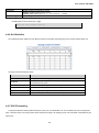
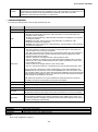
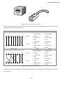
7-Segment LED Display
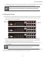
Stack ID (1~9, A~F, 0): indicates the Switch ID. Switch IDs are used to uniquely identify the SW-24400 switches within a stack. The
Switch ID of each switch is shown on the display on the front and is used widely on web pages as well as in the CLI commands of
the Stack group.
Stack ID
Switch ID
1
1
2
2
3
3
4
4
5
5
6
6
7
7
8
8
9
9
A.
10
B.
11
C.
12
D.
13
E.
14
F.
15
0
16
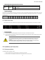
2.1.3 Switch Rear Panel
The rear panel of the switch indicates an AC inlet power socket, which accepts input power from 100 to 240V AC, 50-60Hz.
AC Power Receptacle
The power supply automatically adjusts to line power in the range of 100-240VAC and 50/60 Hz.
Plug the female end of the power cord firmly into the receptacle on the rear panel of the switch. Plug the other end of the
power cord into an electrical outlet.
The device will not work until it is powered. If your networks are active all the time, consider using a
UPS (Uninterrupted Power Supply) for your device to better avoid network data loss or network
downtime.
In some areas, installing a surge suppression device may also help to protect your Managed Switch
from being damaged by unregulated surges to the switch or the power adapter.
2.2 Installation and Connection
2.2.1 Desktop Installation
To install the switch on desktop or shelf:
1.
Attach the rubber feet to the recessed areas on the bottom of the switch.
2.
Place the switch on the desktop or the shelf near an AC power source, as shown below.
15
User’s Manual: SW-24400
3.
Keep enough ventilation space between the switch and the surrounding objects.
4.
Connect the switch to network devices.
a.
Connect one end of a standard network cable to the 10/100/1000 RJ-45 ports on the front of the Managed Switch
b.
Connect the other end of the cable to the network devices.
Connection to the switch requires UTP Category 5 network cabling with RJ-45 tips. For more
information, please see the Cabling Specifications in Appendix A.
5.
Supply power to the switch.
a.
Connect one end of the power cable to the switch.
b.
Connect the power plug of the power cable to a standard wall outlet.
c.
When the switch receives power, the Power LED should remain solid Green.
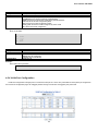
2.2.2 Rack Mounting
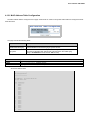
To install the switch in a 19-inch standard rack, follow the instructions described below.
1.
Place the switch on a hard flat surface, with the front panel positioned towards the front side.
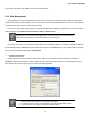
2.
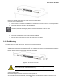
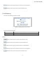
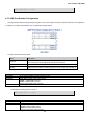
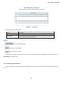
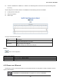
Attach the rack-mount bracket to each side of the switch with supplied screws attached to the package. See the illustration
below for a diagram on how to attach brackets to one side of the switch
Figure2-1 - Attach brackets to the switch.
You must use the screws supplied with the mounting brackets. Damage caused to the parts by
using incorrect screws will invalidate the warranty.
3.
Secure the brackets tightly.
4.
Follow the same steps to attach the second bracket to the opposite side.
5.
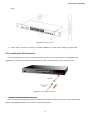
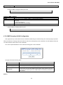
After the brackets are attached to the switch, use suitable screws to securely attach the brackets to the rack, as shown
16
User’s Manual: SW-24400
below.
Figure2-2 - Mounting to a Rack
6.
Refer to steps 4 and steps 5 of section 2.2.1 Desktop Installation to connect network cabling and supply power.
2.2.3 Installing the SFP transceiver
This section describes how to insert an SFP transceiver into an SFP slot. SFP transceivers are hot-pluggable and hotswappable. You can plug-in and out the transceiver to/from any SFP port without having to power down the switch.
Figure 2-3 - Plug-in the SFP transceiver
Approved i3 International SFP Transceivers
This i3 International Managed Switch supports both Single mode and Multi-mode SFP transceivers. Check with technical
support: support@i3international for the current list of approved transceivers.
17
User’s Manual: SW-24400
Use i3 International-approved SFPs on the switch. Unsupported SFP transceivers will not be
recognized.
Before connecting other switches, workstations or Media Converters:
1.
Ensure both sides of the SFP transceiver are with the same media type, for example: 1000Base-SX to 1000Base-SX,
1000Bas-LX to 1000Base-LX.
2.
Check whether the fibre-optic cable type matches the SFP transceiver model.
a.
To connect to 1000Base-SX SFP transceivers, use the Multi-mode fibre cable. One side must be a male duplex
LC connector.
b.
To connect to 1000Base-LX SFP transceivers, use the Single-mode fibre cable. One side must be a male duplex
LC connector.
Connect the fibre cable
1.
Attach the duplex LC connector on the network cable to the SFP transceiver.
2.
Connect the other end of the cable to a device – switches with SFP installed, fibre NIC on a workstation or a Media
Converter.
3.
Check the LNK/ACT LED of the SFP slot on the front of the Managed Switch. Ensure that the SFP transceiver is operating
correctly.
4.
Check the Link mode of the SFP port if the link failed. To work with some fiber-NICs or Media Converters, setting the Link
mode to “1000 Force” is needed.
Remove the transceiver module
1.
Check with your network administrator to make sure there is no network activity. If possible, disable the port in advance
using the management interface of the switch or converter.
2.
Remove the Fibre Optic Cable.
3.
Turn the handle of the MGB module to horizontal.
4.
Pull out the module.
Figure 2-4 - Pull out the SFP transceiver
18
User’s Manual: SW-24400
Never pull out the module without pulling the handle or the push bolts on the module.
Forcibly pulling out the module may damage the module and SFP module slot of the
switch.
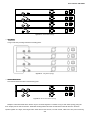
2.3 Stack Installation
The SW-24400 Managed Switch provides a switch stacking function to manage up to 16 switches using a single IP address. Up
to 384 Gigabit Ethernet ports can be managed through a stacking group and you can add ports and functionality as needed. You
can add switches as needed to support more network clients, knowing that your switching fabric will scale to meet increasing traffic
demands.
Two types of stack topologies are supported by the SW-24400:
Chain topology (same as a disconnected ring)
Ring topology
Refer to the Stack section for more details on stack topologies.
2.3.1 Connecting Stacking cables
Before attempting to connect stacking ports, verify that you have the required stack cables. The following cables are used to
connect stacked switches:
SW-HD50:
50cm, Short stack cable –used to connect adjacent SW switches.
SW-HD200:
200cm, Long / Redundant stack cable – used to connect the top and bottom SW switches of a stack.
There are two high-performance HDMI-like Stack ports on the rear panel for a proprietary management stack. Only i3
International SW-HD50 and SW-HD200 cross-over HDMI cables can be used. The following are instructions for stacking using
these cables:
1.
Plug one end of the cable in the “STX1 / Cascade Down” port and the other end to the ”STX2 / Cascade UP” port of next
device.
2.
Repeat the step for every device in the stack cluster.
Figure2-5 - A stacking connection
19
User’s Manual: SW-24400
3.
To implement stack redundancy, use the long stack cable –SW-HD200 to connect the stack port marked “STX1 / Cascade
Down” on the bottom switch to the port marked “STX2 / Cascade Up” on the top switch of the stack.
The stack port is for management and data packets to be transmitted between other SW stackable
switches, the stack ports can’t be configured with Layer 2 features via the management interface.
4.
Power up the stack switches.
2.3.2 Management Stacking
The stack operation of the SW Managed Switch supports Plug and Play Stacking connections and auto stack configuration.
1.
Once the stack is operational, the Stack Master is automatically elected. The Stack master is indicated by a lit green
“Master” LED on the front panel as shown below.
2.
When an SW Switch is added to the stack, a Switch ID is automatically assigned to the switch. The automatic SID
assignment can be modified by choosing a different Switch ID on the Stack Configuration page. This method allows
Switch IDs to be assigned so that it is easier for the user to remember the ID of each switch.
3.
Connect the RS-232 serial cable to the console port on the front of the Stack Master, then join the SW Switch to start
switch management.
The stack switch with lowest priority ID or MAC Address number will become Master. Only the Master
switch’s management interface (console, telnet, web and SNMP) is accessible.
A stack of up to 16 i3 International SW Switches may be built. If there is a space limitation or power issue and you wish to stack
all the switches in different racks, use long stack cables “SW-HD200” to connect two stacks.
20
User’s Manual: SW-24400
Figure2-6 - Separated Stack connection
21
User’s Manual: SW-24400
3. SWITCH MANAGEMENT
This chapter explains the methods that you can use to configure management access to the Managed Switch. It describes the
types of management applications and the communication and management protocols that deliver data between your management
device (workstation or personal computer) and the system. It also contains information about port connection options.
This chapter covers the following topics:
Requirements
Management Access Overview
Administration Console Access
Web Management Access
SNMP Access
3.1 Network and System Requirements
Workstations running Windows 98/ME, NT4.0, 2000/XP, MAC OS9 or later, Linux, UNIX or other platforms compatible
with TCP/IP protocols.
Workstation installed with Ethernet NIC (Network Interface Card)
Serial Port connection (Terminal)
An above PC with COM Port (DB9 / RS-232) or USB-to-RS-232 converter
Ethernet Port connection
Network cables - Use standard network (UTP) cables with RJ45 connectors.
Above Workstation installed with WEB Browser and JAVA runtime environment Plug-in
3.2 Management Access Overview
The following methods can be used to manage the switch
An administration console
Web browser interface
An external SNMP-based network management application
The administration console and Web browser interface supports are embedded in the Managed Switch software and are
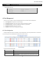
available for immediate use. Each of these management methods has their own advantages. The table below compares the three
management methods.
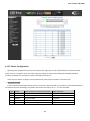
3.2.1 Administration Console
The console port is a DB9, RS-232 male serial port connector for direct connection to a terminal device. Diagnostic information
22
User’s Manual: SW-24400
including IP Address setting, factory reset, port management, link status and system settings are provided through this interface.
Users can use the attached RS-232 cable in the package and connect to the console port on the device. After the connection,
users an run any terminal emulation program (Hyper Terminal, ProComm Plus, PuTTY, Telix, Winterm and so on) to enter the
startup screen of the device.
The administration console is an internal, character-oriented, and command line user interface for performing system
administration such as displaying statistics or changing option settings. Using this method, you can view the administration console
from a terminal, personal computer, Apple Macintosh, or workstation connected to the switch's console (serial) port.
There are two ways to use this management method: via direct access or modem port access.
Figure3-1 - Console management connection
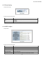
Direct Access
Direct access to the administration console is achieved by directly connecting a terminal or a PC equipped with a terminalemulation program (such as HyperTerminal) to the Managed Switch console (serial) port. A straight DB9 RS-232 cable is required
to connect the switch to the PC. After making this connection, configure the terminal-emulation program to use the following
parameters:
The default parameters are:
115200 bps
8 data bits
No parity
1 stop bit
23
User’s Manual: SW-24400
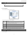
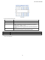
Figure3-2 - Terminal parameter settings as seen on Windows XP
You can change these settings after you log on. A Macintosh or PC attachment can use any terminal-emulation program for
connecting to the terminal serial port. A workstation attachment under UNIX can use an emulator such as TIP.
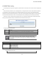
The CLI groups all the commands in appropriate modes according to the nature of the command. A sample of the CLI
command modes are described below. Each of the command modes supports specific software commands.
Command Groups:
System
System settings and reset options
Stack
Stack management
IP
IP configuration and Ping
Port
Port management
MAC
MAC address table
VLAN
Virtual LAN
PVLAN
Private VLAN
Security
Security management
STP
Spanning Tree Protocol
IGMP
Internet Group Management Protocol snooping
Aggr
Link Aggregation
LACP
Link Aggregation Control Protocol
LLDP
Link Layer Discovery Protocol
LLDPMED
Link Layer Discovery Protocol Media
PoE
Power Over Ethernet
QoS
Quality of Service
Mirror
Port mirroring
Config
Load/Save of configuration via TFTP
Firmware
Download of firmware via TFTP
24
User’s Manual: SW-24400
UPnP
Universal Plug and Play
MVR
Multicast VLAN Registration
Voice VLAN
Specific VLAN for voice traffic
SMTP
SMTP control configure
Show
Display the current information
3.2.2 Command Line Interface
When accessing the management interface for the switch over a direct connection to the server’s console port or via a Telnet
connection, the switch can be managed by entering command keywords and parameters at the prompt. Using the switch's
command-line interface (CLI) is very similar to entering commands on a UNIX system.
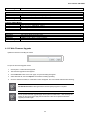
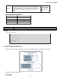
Once the terminal has connected to the device, turn the SW Managed Switch on. The terminal will display that it is running
testing procedures. The following message asks for the login username and password. The factory default password and login is
Username: admin; Password: admin
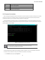
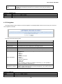
Figure3-3 - SW Managed Switch Console Login screen
For security reasons, change and memorize the new password after this setup.
The console only accepts lower case commands.
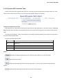
The SW Managed Switch is shipped with the following IP address. IP Address: 192.0.0.20. Subnet Mask: 255.255.255.0
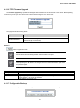
To check the current IP address or modify a new IP address for the Switch, do the following:
1.
On the Switch/> prompt, input “ip configuration”.
25
User’s Manual: SW-24400
2.
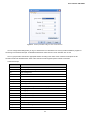
The screen displays the current IP address, Subnet Mask and Gateway as shown below.
Figure3-4 - IP information screen
To change the IP address:
1.
On the Switch/> prompt, enter the following command and press <Enter>
Switch/> ip setup 192.168.0.101 255.255.255.0 192.168.0.253 1
The above command applies the following settings to the switch.
IP: 192.168.0.101
Subnet Mask: 255.255.255.0
Gateway: 192.168.0.253
VLAN ID: 1
2.
Repeat Step 1 to confirm the IP setting change.
If the IP address is successfully configured, the Managed Switch will apply the new IP address setting immediately. You can
access the Web interface through the new IP address.
If you do not familiar with console command or the related parameter, enter “help” anytime in
console to get the help description.
You can change these settings, if desired, after you log on. This management method is often preferred because you can
remain connected and monitor the system during system reboots. Also, certain error messages are sent to the serial port,
regardless of the interface through which the associated action was initiated. A Macintosh or PC attachment can use any terminalemulation program for connecting to the terminal serial port. A workstation attachment under UNIX can use an emulator such as
TIP.
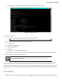
3.2.2.1. Telnet Login
The Managed Switch also supports Telnet for remote management. The switch asks for the user name and password during a
26
User’s Manual: SW-24400
remote login using Telnet. Input “admin” as the username & password.
3.2.3. Web Management
The Managed Switch can be accessed from anywhere on the network through a standard browser capable of handling Java
applets such as Microsoft Internet Explorer as if you were directly connected to the Managed Switch's console port. After setting an
IP address for the switch, enter the address into the browser.
You can then use your Web browser to list and access the Managed Switch configuration parameters from one central location.
Web Management requires Microsoft Internet Explorer, Safari or Mozilla Firefox.
By default, IE7.0 or later prevents Java Applets from opening sockets. The user has to explicitly
modify the browser settings to enable Java Applets to use network ports.
The manager PC must be set on same the IP subnet address with the Managed Switch. For example, the default IP address of
the SW Managed Switch is 192.0.0.20, thus the manager PC should be set at 192.0.0.x (where x is a number between 1 and 254,
except 100), and the default subnet mask is 255.255.255.0.
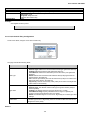
Logging onto the switch
Using a web browser, enter the default IP address of the switch to access the Web interface. The default IP Address is:
192.0.0.20. A login screen will appear. Enter the default username admin with password admin (or the username/password you
have changed via console) to login to the main screen of the Managed Switch.
1.
2.
3.
IP address changes are in effect immediately after clicking the Save button. You will
need to use the new IP address to access the web interface.
For security reasons, change and memorize the new password after this first setup.
The web interface only accepts commands in lowercase letters.
27
User’s Manual: SW-24400
3.2.3.1. Main Web Page
The SW-24400 Managed Switch provides a web-based browser interface for configuration and management using the web
browser of your choice. This chapter describes how to use the Managed Switch’s web interface.
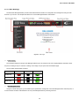
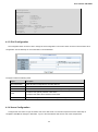
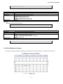
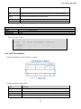
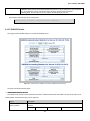
Figure3-5 - Main Page
Panel Display
The web agent displays an image of the Managed Switch’s ports. The Mode can be set to display different information about
the ports, including Link up or Link down. Clicking on the image of a port opens the Port Statistics page.
The port states are illustrated as follows:
State
Disabled
Down
Link
RJ-45 Ports
SFP Ports
Stack Ports
Main Navigation Pane
Using the onboard web agent, you can define system parameters, manage and control the Managed Switch and all its ports, or
monitor network conditions. Administrators can set up the Managed Switch by selecting functions.
28
User’s Manual: SW-24400
Navigating web management screens
Common interface features encountered in web management are given below with a description of their function. Exceptions
and unique interface items will be specified in their corresponding sections:
Auto-refresh
: Check this box to enable an automatic refresh of the page at regular intervals.
: Click to refresh the page; any changes made locally will be undone.
: Clear all statistics. By default, clears all counters except where noted.
: Click to save changes. Except where noted, changes are applied only after clicking Save.
: Click to undo any changes made locally and revert to previously saved values.
: Click to undo any changes made locally and revert to previously saved values.
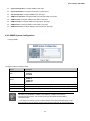
3.2.4. SNMP-Based Network Management
You can use an external SNMP-based application to configure and manage the switch. This management method requires the
SNMP agent on the switch and the SNMP Network Management Station to use the same community string. This management
method, in fact, uses two community strings: the get community string and the set community string. If the SNMP Network
management Station only knows the set community string, it can read and write to the MIBs. However, if it only knows the get
community string, it can only read MIBs. The default gets and sets community strings for the Managed Switch are public.
29
User’s Manual: SW-24400
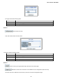
Figure3-6 – SNMP management setup
3.3 Using this Manual
Except as noted, this manual provides configuration details for features of the SW-24400 managed switch in order of appearance
on the ewb management’s Main Navigation Pane (see above for more details). A screenshot is provided, along with a table of the
screen’s interface objects (buttons, checkboxes, etc.) A description of the interface object’s functions is given. The corresponding
console commands; their syntax and parameters are listed. Description of interface objects common to all pages can be found in
the Web Management section.
30
User’s Manual: SW-24400
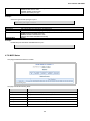
4. CONFIGURATION
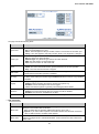
4.1 System
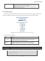
Use the System menu items to display and configure basic administrative details of the Managed Switch. Under System the
following topics are provided to configure and view the system information:
System Information: The switch system information is provided here.
IP Configuration: Configure the switch-managed IP information.
IPv6 Configuration: Configure the switch-managed IPv6 information.
Users Configuration: An overview of the current users. Currently the only way to login as another user on the web server
is to close and reopen the browser.
Users Privilege Levels: An overview of the privilege levels.
NTP Configuration: Configure NTP.
UPnP: Configure UPnP.
DHCP Relay: Configure DHCP Relay.
DHCP Relay Statistics: Provides statistics for DHCP relay.
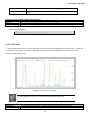
CPU Load: This page displays the CPU load, using a SVG graph.
System Log: The switch system log information is provided here.
Detailed Log: The switch system detailed log information is provided here.
Remote Syslog: Configure remote syslog.
SMTP Configure: Configure SMTP.
Web Firmware Upgrade: Update firmware controlling the switch.
TFTP Firmware Upgrade: Upgrade the firmware via TFTP server
Configuration Backup: You can save the switch configuration. The configuration file is in XML format with a hierarchy of
tags.
Configuration Upload: You can load the switch configuration. The configuration file is in XML format with a hierarchy of
tags.
Factory Default: Reset the configuration of the stack switch. the IP configuration is retained.
System Reboot: Restart the stack switch. After restart, the stack switch will boot normally.
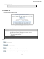
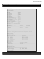
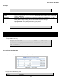
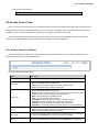
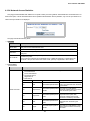
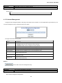
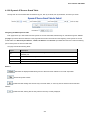
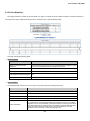
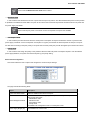
4.1.1 System Information
System Information provides information on the current device
The following fields are included:
Object
Description
31
User’s Manual: SW-24400
Contact
The system contact configured in Configuration | System | Information | System Contact.
Name
The system name configured in Configuration | System | Information | System Name.
Location
The system location configured in Configuration | System | Information | System Location.
MAC Address
The MAC Address of this switch.
Power Status
Indicate AC / DC power supply input of this switch.
Temperature
Indicate main chipset temperature.
System Date
The current (GMT) system time and date. The system time is obtained through the
configured SNTP Server, if any.
System Uptime
The period of time the device has been operational.
Switch ID
The switch ID.
Software Version The software version of the switch.
Console: System Log
Description
Syntax
Parameters
Show or clear the system log.
system log [<log_id>] [all|info|warning|error] [clear]
<log_id>: System log ID or range (default: All entries)
all: Show all levels (default)
info: Show information
warning: Show warnings
error: Show errors
clear: Clear log
Example:
To show system log:
Switch/>system log
Number of entries:
Info
: 2
Warning: 0
Error : 0
All
: 2
ID
---1
2
Level
-----Info
Info
Time
------------------------1970-01-01 Thu 00:00:04 +0000
Message
------Switch just made a cold boot.
Link up on port 10
Console: System Prompt
Description
Syntax
Parameters
Set the CLI prompt string.
system prompt <prompt>
<prompt>: CLI prompt string
Example:
To change CLI title:
Switch/>system prompt SW-24400
Console: System Configuration
Description
Syntax
Parameters
Show system configuration.
system configuration [all] [<port_list>]
all: Show all switch configuration, default: Show system configuration
<port_list>: Port list or 'all', default: All ports
Example:
Display system information:
32
User’s Manual: SW-24400
SWITCH/>System configuration
System Contact :
System Name
: SW-24400P
System Location :
Timezone Offset : 0
CLI Prompt
: SWITCH
MAC Address
: 00-30-4f-76-27-10
Power Status
: AC Power
Temperature
: 49.5 C - 121.1 F
System Time
: 1970-01-01 Thu 00:08:08 +0000
System Uptime
: 00:08:08
Software Version: 1.5b100623
Software Date
: 2010-06-23 15:43:02 +0800
Previous Restart: Cold
SID
--1
Software Version
--------------1.5b100623
Console: System Name
Description
Syntax
Parameters
Set or show the system name.
system name [<name>]
<name>: System name or 'clear' to clear. Only dashes and alphanumeric characters are permitted.
The first character must be alphabetic and the last character must not be a dash.
Example:
To set device title:
Switch/>System name SW-24400-LAB
Console: System Contact
Description
Syntax
Parameters
Default Setting
Set or show the system contact.
system contact [<contact>]
<contact>: System contact string. Use 'clear' or "" to clear the string. No blank or space characters
are permitted as part of a contact. (only in CLI)
empty
Example:
To set device contact:
Switch/>System contact SW-24400-Test
Console: System Location
Description
Syntax
Parameters
Default Setting
Set or show the system location.
system location [<location>]
<location>: System location string. Use 'clear' or "" to clear the string. In CLI, no blank or space
characters are permitted as part of a contact.
empty
Example:
To set device location:
Switch/>System location 9F-LAB
Console: System Timezone
Description
Syntax
Set or show the system timezone offset.
system timezone [<offset>]
33
User’s Manual: SW-24400
Parameters
Default Setting
<offset>: Time zone offset in minutes (-720 to 720) relative to UTC
0
Example:
To set timezone:
Switch/>system timezone 0
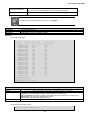
4.1.2 IP Configuration
Fill out the IP Address, Subnet Mask and Gateway for the device.
The Current column is used to show the active IP configuration.
Object
Description
DHCP Client
Enable the DHCP client by checking this box. If DHCP fails and the configured IP address is
zero, DHCP will retry. If DHCP fails and the configured IP address is non-zero, DHCP will
stop and the configured IP settings will be used. The DHCP client will announce the
configured System Name as hostname for DNS lookup.
IP Address
Provide the IP address of this switch in dotted decimal notation.
IP Mask
Provide the IP mask of this switch dotted decimal notation.
IP Router
Provide the IP address of the router in dotted decimal notation.
VLAN ID
Provide the managed VLAN ID. The allowed range is 1 through 4095.
DNS Server
Provide the IP address of the DNS Server in dotted decimal notation.
DNS Proxy
When DNS proxy is enabled, DUT will relay DNS requests to the current configured DNS
server on DUT, and reply as a DNS resolver to the client device on the network.
Console: IP Configuration
Description
Syntax
Show IP configuration.
ip configuration
Example:
Show IP configuration:
34
User’s Manual: SW-24400
Switch/>ip configuration
IP Configuration:
=================
DHCP Client
: Disabled
IP Address
: 192.0.0.20
IP Mask
: 255.255.255.0
IP Router
: 192.168.0.1
DNS Server
: 0.0.0.0
VLAN ID
: 1
DNS Proxy
: Disabled
IPv6 AUTOCONFIG mode
: Disabled
IPv6 Link-Local Address: fe80::230:4fff:fe24:4d1
IPv6 Address
: ::192.0.0.20
IPv6 Prefix
: 96
IPv6 Router
: ::
IPv6 VLAN ID
: 1
4.1.3 IPv6 Configuration
The Configured column is used to view or change the IPv6 configuration. The Current column is used to show the active IPv6
configuration. See the Glossary for more information on IPv6 addresses.
The page includes the following fields:
Object
Description
Auto Configuration
Enable IPv6 auto-configuration by checking this box.
Address
Provide the IPv6 address of this switch.
Prefix
Provide the IPv6 Prefix of this switch. The allowed range is 1 through 128.
Provide the IPv6 gateway address of this switch.
Router
Provide the IPv6 SNTP Server address of this switch.
VLAN ID
Provide the managed VLAN ID. The allowed range is 1 through 4095.
4.1.4 Users Configuration
Configure and view users. To login as another user on the web server is to close and reopen the browser. After setup is
completed, click Save for changes to take effect. Log on to the web interface with the new user name and password.
35
User’s Manual: SW-24400
The page includes the following fields:
Object
Description
Username
The name identifying the user. This is also a link to the Add/Edit User module.
Privilege Level
The privilege level for the user.
Buttons
: Click to add a new user.
Add, edit or delete users from this screen.
The page includes the following fields:
Object
Description
Username
The name identifying the user.
Password
The password of the user.
Privilege Level
The privilege level for the user.
Buttons
: Click to undo any changes made locally and return to the Users page.
: Delete the current user. This button is not available for new configurations (Add new user)
Once the new user is added, the new user entry is shown in the Users Configuration page.
36
User’s Manual: SW-24400
Console: Security Switch User Configuration
Description
Syntax
Show users privilege levels
security switch users configuration
Example:
Enable isolate for port10
SWITCH/>security switch user configuration
Users Configuration:
====================
User Name
----------------------------admin
guest
Privilege Level
--------------15
5
4.1.5 Users Privilege Levels
Configure the privledge levels available to users. After setup is completed, click Save in order for changes to take effect. Log
on to the web interface with the new user name and password.
The page includes the following fields:
37
User’s Manual: SW-24400
Object
Description
Group Name
The name identifying the privilege group. In most cases, a privilege level group consists of
a single module (e.g. LACP, RSTP or QoS), but a few of them contain more than one. The
level groups:
System: Contact, Name, Location, Timezone and Log.
Security: Authentication, System Access Management, Port (contains Dot1x port, MAC
based and the MAC Address Limit), ACL, HTTPS, SSH, ARP Inspection and IP source
guard.
IP: Everything except 'ping'.
Port: Everything except 'VeriPHY'.
Diagnostics: 'ping' and 'VeriPHY'.
Maintenance: CLI- System Reboot, System Restore Default, System Password,
Configuration Save, Configuration Load and Firmware Load. Web- Users, Privilege
Levels and everything in Maintenance.
Debug: Only present in CLI.
Privilege Level
Every privilege level group has an authorization level for the following sub groups:
configuration read-only
configuration/execute read-write
status/statistics read-only
status/statistics read-write (e.g. for clearing of statistics).
Console: Security Switch Privilege Level Configuration
Description
Syntax
Show privilege configuration.
security switch privilege level configuration
Example:
Show privilege level
SWITCH/>security switch privilege level configuration
Privilege Level Configuration:
==============================
Privilege Current Level: 15
Group Name
Privilege Level
CRO CRW SRO SRW
-------------------------------- --- --- --- --Aggregation
5 10
5 10
Debug
15 15 15 15
Diagnostics
5 10
5 10
IGMP_Snooping
5 10
5 10
IP
5 10
5 10
LACP
5 10
5 10
LLDP
5 10
5 10
LLDP-MED
5 10
5 10
MAC_Table
5 10
5 10
MVR
5 10
5 10
Maintenance
15 15 15 15
Mirroring
5 10
5 10
Port_Security
5 10
5 10
Ports
5 10
1 10
Private_VLANs
5 10
5 10
QoS
5 10
5 10
SNMP
5 10
5 10
Security
5 10
5 10
Spanning_Tree
5 10
5 10
System
5 10
1 10
UPnP
5 10
5 10
VLANs
5 10
5 10
Voice_VLAN
5 10
5 10
38
User’s Manual: SW-24400
4.1.6 NTP Configuration
Configure NTP.
The page includes the following fields:
Object
Description
Mode
Indicates the NTP mode operation. Possible modes are:
Enabled
Disabled
Timezone
Allows selecting a time zone according to current location of switch.
Server #
Provide the NTP IPv4 or IPv6 address of this switch.
Console: IP NTP Configuration
Description
Syntax
Default Setting
Show NTP configuration.
ip ntp configuration
NTP Mode : Disabled
Idx Server IP host address (a.b.c.d) or a host name string
--- -----------------------------------------------------1 pool.ntp.org
2 europe.pool.ntp.org
3 north-america.pool.ntp.org
4 asia.pool.ntp.org
5 oceania.pool.ntp.org
Console: IP NTP Mode
Description
Syntax
Parameters
Default Setting
Set or show the NTP mode.
ip ntp mode [enable|disable]
enable: Enable NTP mode
disable: Disable NTP mode
(default: Show NTP mode)
Disable
Example:
Enable NTP mode:
SWITCH/>ip ntp mode enable
Console: IP NTP Server Add
Description
Add NTP server entry.
39
User’s Manual: SW-24400
Syntax
Parameters
Default Setting
ip ntp server add <server_index> <ip_addr_string>
<server_index>: The server index (1-5)
<ip_addr_string>: IP host address (a.b.c.d) or a host name string
Disable
Example:
To add NTP server:
SWITCH/>ip ntp server add 1 60.249.136.151
Console: IP NTP Server IPv6 Add
Description
Syntax
Parameters
Default Setting
Add NTP server IPv6 entry.
ip ntp server ipv6 add <server_index> <server_ipv6>
<server_index>: The server index (1-5)
<server_ipv6>: IPv6 server address.
Disable
Example:
To add IPv6 NTP server:
SWITCH/>ip ntp server ipv6 add 1 2001:7b8:3:2c::123
Console: IP NTP Server Delete
Description
Syntax
Parameters
Delete NTP server entry.
ip ntp server delete <server_index>
<server_index>: The server index (1-5)
<server_ipv6>: IPv6 server address.
Example:
To delete NTP server:
SWITCH/>ip ntp server delete 1
4.1.7 UPnP Configuration
Configure UPnP to simplify the implementation of networks and installation of computer components.
The page includes the following fields:
Object
Description
Mode
Indicates the UPnP operation mode. Possible modes are:
Enabled
Disabled
When the mode is enabled, two ACEs are added automatically to trap UPNP related
packets to CPU. The ACEs are automatically removed when the mode is disabled.
TTL
The TTL value is used by UPnP to send SSDP advertisement messages. Valid values
are in the range 1 to 255.
Advertising Duration
Specify how often control points should receive a SSDP advertisement message from
this switch.
Console: UPnP Configuration
Description
Syntax
Show UPnP configuration.
upnp configuration
40
User’s Manual: SW-24400
Example:
Show UPnP configuration.
SWITCH/>upnp configuration
UPnP Configuration:
===================
UPnP Mode
: Disabled
UPnP TTL
: 4
UPnP Advertising Duration : 100
Console: UPnP Mode
Description
Syntax
Parameters
Default Setting
Set or show the UPnP mode.
upnp mode [enable|disable]
enable : Enable UPnP
disable: Disable UPnP
(default: Show UPnP mode)
Disable
Example:
Enable the UPnP mode.
SWITCH/>upnp mode enable
Console: UPnP TTL
Description
Syntax
Parameters
Default Setting
Set or show the TTL value of the IP header in SSDP messages.
upnp ttl [<ttl>]
<ttl>: ttl range (1..255), default: Show UPnP TTL
4
Example:
Set the value 10 for TTL value of the IP header in SSDP messages.
SWITCH/>upnp ttl 10
Console: UPnP Advertising Duration
Description
Syntax
Parameters
Default Setting
Set or show UPnP Advertising Duration.
upnp advertising duration [<duration>]
<duration>: duration range (100..86400), default: Show UPnP duration range
100
Example:
Set value 1000 for UPnP Advertising Duration.
SWITCH/>upnp advertising duration 1000
4.1.8 DHCP Relay
Configure DHCP Relay. DHCP Relay is used to forward and to transfer DHCP messages between the clients and the server
when they are not on the same subnet domain.
41
User’s Manual: SW-24400
The DHCP option 82 enables a DHCP relay agent to insert specific information into a DHCP request packets when forwarding
client DHCP packets to a DHCP server and remove the specific information from a DHCP reply packets when forwarding server
DHCP packets to a DHCP client. The DHCP server can use this information to implement IP address or other assignment policies.
Specifically the option works by setting two sub-options:
Circuit ID (option 1)
Remote ID (option2).
The Circuit ID sub-option includes information specific to which circuit the request came in on.
The Remote ID sub-option carries information relating to the remote host end of the circuit.
The definition of a Circuit ID in the switch is 4 bytes in length and the format is "vlan_id" "module_id" "port_no". The parameter
"vlan_id" is the first two bytes represented in the VLAN ID. The parameter of "module_id" is the third byte for the module ID (in
standalone switches it is always 0, in stackable switch it signifies the switch ID). The parameter of "port_no" is the fourth byte
indicating the port number.
The Remote ID is 6 bytes in length, and the value is the DHCP relay agent’s MAC address.
The page includes the following fields:
Object
Description
Relay Mode
Indicates the DHCP relay mode operation. Possible modes are:
Enabled
Disabled
Relay Server
Indicates the DHCP relay server IP address.
Relay Information Mode
Indicates the DHCP relay information mode option operation. Possible modes are:
Enabled
Disabled
Relay Information Policy
Indicates the DHCP relay information option policy. Possible policies are:
Replace: Replace the original relay information when a DHCP message that
already contains it is received
Keep: Keep the original relay information when a DHCP message that already
contains it is received.
Drop: Drop the package when a DHCP message already contains relay
information.
Console: Security Network DHCP Relay Configuration
Description
Syntax
Show DHCP relay configuration.
security network dhcp relay configuration
Example:
Show DHCP relay configuration.
42
User’s Manual: SW-24400
SWITCH/>security network dhcp relay configuration
DHCP Relay Configuration:
=========================
DHCP
DHCP
DHCP
DHCP
Relay
Relay
Relay
Relay
Mode
Server
Information Mode
Information Policy
:
:
:
:
Disabled
NULL
Disabled
replace
Console: Security Network DHCP Relay Mode
Description
Syntax
Parameters
Set or show the DHCP relay mode.
security network dhcp relay mode [enable|disable]
enable : Enable DHCP relay mode.
When enabled, agent forwards and transfers DHCP messages between the clients and the server
when if not the same subnet domain. The DHCP broadcast message won't flood.
disable: Disable DHCP relay mode
(default: Show flow DHCP relay mode)
Example:
Enable DHCP relay mode
SWITCH/>security network dhcp relay mode enable
Console: Security Network DHCP Relay Server
Description
Syntax
Parameters
Default Setting
Show or set DHCP relay server.
security network dhcp relay server [<ip_addr>]
<ip_addr>: IP address (a.b.c.d), default: Show IP address
null
Example:
Set DHCP relay server in 192.168.0.20
SWITCH/>security network dhcp relay server 192.168.0.20
Console: Security Network DHCP Relay Information Mode
Description
Syntax
Parameters
Default Setting
Set or show DHCP relay agent information option mode.
When enabled, adds information to DHCP message when forwarding to DHCP server and removed
from message when transferring to DHCP client.
security network dhcp relay information mode [enable|disable]
enable : Enable DHCP relay agent information option mode
disable: Disable DHCP relay agent information option mode
(default: Show DHCP relay agent information option mode)
disable
Example:
Enable DHCP relay agent information option mode.
SWITCH/>security network dhcp relay information mode enable
Console: Security Network DHCP Relay Information Policy
Description
Syntax
Parameters
Set or show the DHCP relay mode.
When DHCP relay information mode operation is enabled, an agent enforces the policy received by
a DHCP message containing relay agent information.
security network dhcp relay information policy [replace|keep|drop]
replace: Replace original relay information on receiving DHCP message already containing it. keep:
Keep original relay information on receiving a DHCP message already containing it.
43
User’s Manual: SW-24400
Default Setting
drop: Drop package when receiving a DHCP message already containing relay information
(default: Show DHCP relay information policy)
replace
Example:
Keep the original relay information when receive a DHCP message that already contains it
SWITCH/>security network dhcp relay information policy keep
4.1.9 DHCP Relay Statistics
The webpage provides statistics for DHCP relay.
The page includes the following fields:
Server Statistics
Object
Description
Transmit to Server
The number of packets relayed from clients to server.
Transmit Error
The number of erroneous packets sent to clients.
Receive from Server
The number of packets received from clients.
Receive Missing Agent
Option
The number of packets received without agent information options.
Receive Missing Circuit ID
The number of packets received in which the Circuit ID option was missing.
Receive Missing Remote ID
The number of packets received in which the Remote ID option was missing.
Receive Bad Circuit ID
The number of packets received in which the Circuit ID option did not match
known circuit ID.
Receive Bad Remote ID
The number of packets received in which the Remote ID option did not match
known Remote ID.
Client Statistics
Object
Description
Transmit to Client
The number of packets relayed from server to client.
Transmit Error
The number of erroneous packets sent to servers.
Receive form Client
The number of packets received from server.
Receive Agent Option
The number of packets received with relay agent information option.
Replace Agent Option
The number of packets replaced in received packets with relay agent information
option.
44
User’s Manual: SW-24400
Keep Agent Option
The number of packets kept in received packets with relay agent information option.
Drop Agent Option
The number of packets dropped in received packets with relay agent information
option.
Console: Security Network DHCP Relay Statistics
Description
Syntax
Parameters
Show or clear DHCP relay statistics.
Security Network DHCP Relay Statistics [clear]
clear: Clear DHCP relay statistics
Example:
Show DHCP relay statistics.
SWITCH/>security network dhcp relay statistics
4.1.10 CPU Load
This page displays the CPU load, using a SVG graph. The load is measured as averaged over the last 100 ms, 1 second and
10 seconds intervals. The last 120 samples are graphed, and the last numbers are displayed as text as well. The console
command provides statistics only.
Figure4-1 – An example CPU Load graph
In order to display the SVG graph, your browser must support the SVG format.
Console: System Prompt
Description
Syntax
Show current CPU load: 100ms, 1s and 10s running average (in percent, zero is idle).
system load
Example:
45
User’s Manual: SW-24400
To show current CPU load:
Switch/>system load
Load average(100ms, 1s, 10s):
1%,
1%,
1%
4.1.11 System Log
The switch system log information is provided.
Figure4-2 - System Log page for a switch in a stack
The page includes the following fields:
Object
Description
ID
The ID (>= 1) of the system log entry.
Level
The level of the system log entry. The following level types are supported:
Info: Information level of the system log.
Warning: Warning level of the system log.
Error: Error level of the system log.
All: All levels.
Time
The time of the system log entry.
Message
The message of the system log entry.
Buttons
: Hide the statistics.
: Download the statistics.
: Updates the system log entries, starting from the first available entry ID.
: Updates the system log entries, ending at the last entry currently displayed.
46
User’s Manual: SW-24400
: Updates the system log entries, starting from the last entry currently displayed.
: Updates the system log entries, ending at the last available entry ID.
4.1.12 Detailed Log
The switch system detailed log information is provided.
Figure 4-2 - Detailed Log page for a switch in a stack
The page includes the following fields:
Object
Description
ID
The ID (>= 1) of the system log entry.
Message
The message of the system log entry.
Buttons
: Click to refresh the page; any changes made locally will be undone.
: Updates the system log entries, starting from the first available entry ID.
: Updates the system log entries, ending at the last entry currently displayed.
: Updates the system log entries, starting from the last entry currently displayed.
: Updates the system log entries, ending at the last available entry ID.
47
User’s Manual: SW-24400
4.1.13 Remote Syslog
Configure remote syslog.
The page includes the following fields:
Object
Description
Mode
Indicates the remote syslog mode operation. Possible modes are:
Enabled
Disabled
Syslog Server IP
Fill in your remote syslog server IP address.
4.1.14 SMTP Configure
Configure SMTP
The page includes the following fields:
Object
Description
SMTP Mode
Controls whether SMTP is enabled on this switch.
SMTP Server
Type the SMTP server name or the IP address of the SMTP server.
SMTP Port
Set port number of SMTP service.
SMTP Authentication
Controls whether SMTP authentication is enabled if authentication is required
when an e-mail is sent.
Authentication User Name
Type the user name for the SMTP server if Authentication is enabled.
48
User’s Manual: SW-24400
Authentication Password
Type the password for the SMTP server if Authentication is enabled.
E-mail From
Type the sender’s E-mail address. This address is used for reply e-mails.
E-mail Subject
Type the subject/title of the e-mail.
E-mail 1 To
Type the receiver’s e-mail address.
E-mail 2 To
Buttons
: Send a test mail to mail server to check this account is available or not.
Console: SMTP Configuration
Description
Syntax
Default Setting
Show SMTP configuration.
smtp configuration
disable
Console: SMTP Mode
Description
Syntax
Parameters
Default Setting
Enable or disable SMTP.
smtp mode [enable|disable]
enable: Enable SMTP mode
disable: Disable SMTP mode
(default: Show SMTP mode)
disable
Console: SMTP Server
Description
Syntax
Parameters
Default Setting
Set or show SMTP server configuration.
smtp server [<server>] [<port>]
<server>: SMTP server address
<port>: SMTP server port
disable
Console: SMTP Authentication
Description
Syntax
Parameters
Default Setting
Enable or disable SMTP authentication configuration.
smtp auth [enable|disable]
enable: Enable SMTP Authentication
disable: Disable SMTP Authentication
(default: Show SMTP Authentication)
disable
Console: SMTP Authentication User
Description
Syntax
Parameters
Default Setting
Set or show SMTP authentication user name.
smtp auth_user [<auth_user_text>]
<auth_user_text>: SMTP Authentication User Name
disable
Console: SMTP Authentication Password
Description
Syntax
Parameters
Default Setting
Set or show SMTP authentication password.
smtp auth_pass [<auth_pass_text>]
<auth_pass_text>: SMTP Authentication Password
disable
Console: SMTP Mailfrom
Description
Syntax
Parameters
Set or show SMTP e-mail sender information.
smtp mailfrom [<mailfrom_text>]
<mailfrom_text>: SMTP E-mail From address
49
User’s Manual: SW-24400
Default Setting
disable
Console: SMTP Mailsubject
Description
Syntax
Parameters
Default Setting
Set or show SMTP e-mail subject.
smtp mailsubject [<mailsubject_text>]
<mailsubject_text>: SMTP E-mail Subject
disable
Console: SMTP Mailto1
Description
Syntax
Parameters
Default Setting
Set or show SMTP primary email.
smtp mailto1 [<mailto1_text>]
<mailto1_text>: SMTP e-mail 1 to address
disable
Console: SMTP Mailto2
Description
Syntax
Parameters
Default Setting
Set or show SMTP secondary email.
smtp mailto2 [<mailto2_text>]
<mailto1_text>: SMTP e-mail 2 to address
disable
4.1.15 Web Firmware Upgrade
Update the firmware controlling the switch.
To open the Firmware Upgrade screen:
1.
Click System -> Web Firmware Upgrade.
2.
The Firmware Upgrade screen appears
3.
Click the Browse button of the main page, an Open File dialog will appear.
4.
Select firmware file, then click Upload. The software will being uploading.
5.
Once the software is loaded, a confirmation screen will appear. The new software will load after rebooting.
DO NOT Power OFF the Managed Switch until the update progress is complete.
Do not quit the Firmware Upgrade page without press the “OK” button - after the image be
loaded. Or the system won’t apply the new firmware. User has to repeat the firmware
upgrade processes again.
50
User’s Manual: SW-24400
4.1.16 TFTP Firmware Upgrade
The Firmware Upgrade page updates the Managed Switch firmware from the TFTP server in the network. Before updating,
make sure you have your TFTP server ready and the firmware image is on the TFTP server.
The page includes the following fields:
Object
Description
TFTP Server IP
Fill in your TFTP server IP address.
Firmware File Name
The name of firmware image.
(Maximum length: 24 characters)
Buttons
: Click to upgrade firmware.
DO NOT Power OFF the Managed Switch until the update is complete.
Do not quit the Firmware Upgrade page before the confirmation image has loaded or
without pressing the “OK” button. The changes will not be saved and firmware update must
be performed again.
Console: Firmware Load
Description
Syntax
Parameters
Load new firmware from TFTP server.
firmware load [<ip_addr_string>|<ipv6_server>] <file_name>
<ip_addr_string>: IP host address (a.b.c.d) or a host name string
<ipv6_server>: TFTP server IPv6 address
<file_name>: Firmware file name
4.1.17 Configuration Backup
This function backs up and reloads saved configurations of the Managed Switch to the local management station.
51
User’s Manual: SW-24400
You can save/view or load the switch configuration. The configuration file is in XML with the following hierarchical tags.
Header tags:
<?xml version="1.0"?> and <configuration>. These tags are mandatory and must be present
at the beginning of the file.
Section tags:
<platform>, <global> and <switch>. The platform section must be the first section tag and this
section must include the correct platform ID and version. The global section is optional and
includes configurations unrelated to specific switch ports. The switch section is optional and
includes configuration which is related to specific switch ports.
Module tags:
<ip>, <mac>, <port> etc. These tags identify a module controlling specific parts of the
configuration.
Group tags:
<port_table>, <vlan_table> etc. These tags identify a group of parameters, typically a table.
Parameter tags:
<mode>, <entry> etc. These tags identify parameters for the specific section, module and
group. The <entry> tag is used for table entries.
Configuration parameters are represented as attribute values. When saving the configuration from the switch, the entire
configuration including syntax descriptions is included in the file. The file may then be modified using an editor and loaded to a
switch.
Save Configuration
1.
Press the Save Configuration button to save the current configuration in the manager workstation.
2.
Chose the file save path in management workstation.
Console: Configuration Save
Description
Syntax
Parameters
Save configuration to TFTP server.
config save <ip_server> <file_name>
<ip_server>: TFTP server IP address (a.b.c.d)
<file_name>: Configuration file name
4.1.18 Configuration Upload
This function allows backup and reload the current configuration of the Managed Switch to the local management station.
Configuration Upload
1.
Click the Browse button of the main page, the Open File dialog will appear.
2.
Select on the configuration file then click Upload. Upload will begin.
3.
The message “Transfer Completed” will appear.
Console: Configuration Load
Description
Syntax
Parameters
Load configuration from TFTP server.
config load <ip_server> <file_name> [check]
<ip_server>: TFTP server IP address (a.b.c.d)
<file_name>: Configuration file name
check: Check configuration file only, default: Check and apply file
52
User’s Manual: SW-24400
4.1.19 Factory Default
You can reset the configuration of the stack switch on this page. Only the IP configuration is retained. The new configuration is
available immediately, which means that no restart is necessary. A screen will appear asking you to confirm the reset. Click Yes to
confirm, No to cancel and return to the Port Status page.
After the Factory button is pressed and the system rebooted, the following settings will be in place:
Default IP address: 192.0.0.20
Subnet mask: 255.255.255.0
Default Gateway: 192.168.0.254
The other setting values will be either disabled or set to “none.”
Console: System Restore Default
Description
Syntax
Parameters
Restore factory default configuration.
system restore default [keep_ip]
keep_ip: Keep IP configuration, default: Restore full configuration
Example:
To restore default value but not reset IP address:
Switch/>system restore default keep_ip
4.1.20 System Reboot
The Reboot page enables the device to be rebooted from a remote location. Once the Reboot button is pressed, re-enter the
login information. After a sixty-second delay, the switch will ask for confirmation. Click the Yes button to reboot, or No to cancel and
return to the Port Status page.
You can also check the SYS LED on the front panel. If the SYS LED is blinking, the firmware is being loaded; if the SYS LED is
on, the web browser may be used to login to the Switch.
Console: System Reboot
Description
Syntax
Reboot the system without changing settings
system reboot
4.2 Simple Network Management Protocol
4.2.1 SNMP Overview
The Simple Network Management Protocol (SNMP) is an application layer protocol that facilitates the exchange of
management information between network devices. It is part of the Transmission Control Protocol/Internet Protocol (TCP/IP)
protocol suite. SNMP enables network administrators to manage network performance, find and solve network problems, and plan
for network growth.
Use the SNMP Menu to display or configure the Managed Switch's SNMP function. The webpage has the following items:
53
User’s Manual: SW-24400
System Configuration: Configure SNMP on this page.
System Information: The system information is provided here.
Trap Configuration: Configure SNMP trap on this page.
SNMPv3 Communities: Configure SNMPv3 communities table on this page.
SNMPv3 Users: Configure SNMPv3 users table on this page.
SNMPv3 Groups: Configure SNMPv3 groups table on this page.
SNMPv3 Views: Configure SNMPv3 views table on this page.
SNMPv3 Accesses: Configure SNMPv3 accesses table on this page.
4.2.2 SNMP System Configuration
Configure SNMP.
The page includes the following fields:
Object
Description
Mode
Indicates the SNMP mode operation. Possible modes are:
Enabled
Disabled
Version
Indicates the SNMP supported version. Possible versions are:
SNMP v1
SNMP v2c
SNMP v3
Read Community
Indicates the community read access string to permit access to SNMP agent. **
Write Community
Indicates the community write access string to permit access to SNMP agent. **
Engine ID
Indicates the SNMPv3 engine ID. ***
** The allowed string length is 0 to 255 and ASCII characters from 33 to 126 may be used.
The field is only applicable to SNMPv1 and SNMPv2c. SNMPv3 uses USM for
authentication and privacy. The community string is associated with the SNMPv3
communities table
*** The string must contain an even number between 10 and 64 hexadecimal digits, but allzeros and all-'F's are not allowed. Change of the Engine ID will clear all original local users.
54
User’s Manual: SW-24400
Console: Security Switch SNMP Configuration
Description
Syntax
Show SNMP configuration.
security switch snmp configuration
Example:
Show SNMP configuration.
SWITCH/>security switch snmp configuration
SNMP Configuration:
===================
SNMP Mode
SNMP Version
Read Community
Write Community
Trap Mode
Trap Version
Trap Community
Trap Destination
Trap IPv6 Destination
Trap Authentication Failure
Trap Link-up and Link-down
Trap Inform Mode
Trap Inform Timeout (seconds)
Trap Inform Retry Times
Trap Probe Security Engine ID
Trap Security Engine ID
Trap Security Name
:
:
:
:
:
:
:
:
:
:
:
:
:
:
:
:
:
Enabled
2c
public
private
Disabled
1
public
::
Enabled
Enabled
Enabled
1
5
Enabled
None
SNMPv3 Engine ID : 800007e5017f000001
SNMPv3 Communities Table:
Idx Community
--- -------------------------------1
public
2
private
Source IP
Source Mask
--------------- --------------0.0.0.0
0.0.0.0
0.0.0.0
0.0.0.0
Number of entries: 2
SNMPv3 Users Table:
Idx Engine ID User Name
Level
Auth Priv
--- --------- -------------------------------- -------------- ---- ---1
Local
default_user
NoAuth, NoPriv None None
Number of entries: 1
SNMPv3 Groups Table;
Idx Model Security Name
--- ----- -------------------------------1
v1
public
2
v1
private
3
v2c
public
4
v2c
private
5
usm
default_user
Group Name
-------------------------------default_ro_group
default_rw_group
default_ro_group
default_rw_group
default_rw_group
Number of entries: 5
SNMPv3 Views Table:
Idx View Name
View Type OID Subtree
--- -------------------------------- --------- -------------------------------1
default_view
included .1
Number of entries: 1
SNMPv3 Accesses Table:
Idx Group Name
--- -------------------------------1
default_ro_group
2
default_rw_group
Model
----any
any
Level
-------------NoAuth, NoPriv
NoAuth, NoPriv
Number of entries: 2
Console: Security Switch SNMP Mode
Description
Set or show the SNMP mode.
55
User’s Manual: SW-24400
Syntax
Parameters
Default Setting
security switch snmp mode [enable|disable]
enable : Enable SNMP
disable: Disable SNMP
(default: Show SNMP mode)
Enable
Example:
Disable SNMP mode.
SWITCH/>security switch snmp mode disable
Console: Security Switch SNMP Version
Description
Syntax
Parameters
Default Setting
Set or show the SNMP protocol version.
security switch snmp version [1|2c|3]
1: SNMP version 1
2c: SNMP version 2c
3: SNMP version 3
(default: Show SNMP version)
2c
Example:
Set SNMP in version 3.
SWITCH/>security switch snmp version 3
Console: Security Switch SNMP Read Community
Description
Syntax
Parameters
Default Setting
Set or show the community string for SNMP read access.
security switch snmp read community [<community>]
<community>: Community string. Use 'clear' or "" to clear the string
(default: Show SNMP read community)
public
Example:
Set SNMP read community private.
SWITCH/>security switch snmp read community private
Console: Security Switch SNMP Write Community
Description
Syntax
Parameters
Default Setting
Set or show the community string for SNMP write access.
security switch snmp write community [<community>]
<community>: Community string. Use 'clear' or "" to clear the string
(default: Show SNMP write community)
private
Example:
Set public value in SNMP write community.
SWITCH/>security switch snmp write community public
Console: Security Switch SNMP Trap Probe Security Engine ID
Description
Syntax
Parameters
Show SNMP trap security engine ID probe mode.
security switch snmp trap probe security engine id [enable|disable]
enable : Enable SNMP trap security engine ID probe
disable: Disable SNMP trap security engine ID probe
(default: Show SNMP trap security engine ID probe mode)
56
User’s Manual: SW-24400
Default Setting
Enable
Example:
Disable SNMP trap probe security engine ID
SWITCH/>security switch snmp trap probe security engine id disable
Console: Security Switch SNMP Trap Security Engine ID
Description
Syntax
Parameters
Default Setting
Set or show SNMP trap security engine ID.
security switch snmp trap security engine id [<engineid>]
<engineid>: Engine ID, the format may not be all zeros or all 'ff'H and is restricted to 5 - 32 octet
string
Enable
Example:
Set the SNMP trap security engine ID
SWITCH/>security switch snmp trap security engine id 800007e5017f000011
4.2.3 SNMP System Information Configuration
The switch system information is provided here.
The page includes the following fields:
Object
Description
System Contact
The textual identification of the contact person for this managed node together with
information on how to contact this person. The allowed string length is 0 to 255, and the
allowed content is the ASCII characters from 32 to 126.
System Name
An administratively assigned name for this managed node. No space characters are
permitted. The first character must be alphanumeric. The last character must not be a
minus sign. The allowed string length is 0 to 255.
System Location
The physical location of this node (e.g., telephone closet, 3rd floor). The allowed string
length is 0 to 255, and the allowed content is the ASCII characters from 32 to 126.
4.2.4 SNMP Trap Configuration
Configure SNMP trap.
57
User’s Manual: SW-24400
The page includes the following fields:
Object
Description
Trap Mode
Indicates the SNMP trap mode operation. Possible modes are:
Enabled
Disabled
Trap Version
Indicates the SNMP trap supported version. Possible versions are:
SNMP v1
SNMP v2c
SNMP v3
Trap Community
Indicates the community access string when send SNMP trap packet. The
allowed string length is 0 to 255, and the allowed content is the ASCII
characters from 33 to 126.
Trap Destination Address
Indicates the SNMP trap destination address.
Trap Destination IPv6 Address
Provide the trap destination IPv6 address of this switch.
Trap Authentication Failure
Indicates the SNMP entity is permitted to generate authentication failure
traps. Possible modes are:
Enabled
Disabled
Trap Link-up and Link-down
Indicates the SNMP trap link-up and link-down mode operation. Possible
modes are:
Enabled
Disabled
Trap Inform Mode
Indicates the SNMP trap inform mode operation. Possible modes are:
Enabled
Disabled
Trap Inform Timeout (seconds)
Indicates the SNMP trap inform timeout. The allowed range is 0 to 2147.
Trap Inform Retry Times
Indicates the SNMP trap inform retry times. The allowed range is 0 to 255.
Console: Security Switch SNMP Trap Mode
Description
Syntax
Parameters
Default Setting
Set or show the SNMP trap mode.
security switch snmp trap mode [enable|disable]
enable : Enable SNMP traps
disable: Disable SNMP traps
(default: Show SNMP trap mode)
disable
Example:
58
User’s Manual: SW-24400
Enable SNMP trap mode.
SWITCH/>security switch snmp trap mode enable
Console: Security Switch SNMP Trap Version
Description
Syntax
Parameters
Default Setting
Set or show the SNMP trap protocol version.
security switch snmp trap version [1|2c|3]
1 : SNMP version 1
2c: SNMP version 2c
3 : SNMP version 3
(default: Show SNMP trap version)
1
Example:
Set SNMP trap version in version 2c.
SWITCH/>security switch snmp trap version 2c
Console: Security Switch SNMP Trap Community
Description
Syntax
Parameters
Default Setting
Set or show the community string for SNMP traps.
security switch snmp trap community [<community>]
<community>: Community string. Use 'clear' or "" to clear the string
(default: Show SNMP trap community)
public
Example:
Set private value for SNMP trap community.
SWITCH/>security switch snmp trap community private
Console: Security Switch SNMP Trap Destination
Description
Syntax
Parameters
Set or Show the SNMP trap destination address.
security switch snmp trap destination [<ip_addr_string>]
<ip_addr_string>: IP host address (a.b.c.d) or a host name string
Example:
Set SNMP trap destination address for 192.168.0.20
SWITCH/>security switch snmp trap destination 192.168.0.20
Console: Security Switch SNMP Trap IPv6 Destination
Description
Syntax
Parameters
Default Setting
Set or Show the SNMP trap destination IPv6 address.
security switch snmp trap ipv6 destination [<ipv6_addr>]
<ipv6_addr>: End IPv6 address. See the glossary for more details about IPv6.
private
Example:
Set SNMP trap IPv6 destination address for 2001::0001
SWITCH/>security switch snmp trap ipv6 destination 2001::0001
59
User’s Manual: SW-24400
Console: Security Switch SNMP Trap Authentication Failure
Description
Syntax
Parameters
Default Setting
Set or show the SNMP authentication failure trap mode.
security switch snmp trap authentication failure [enable|disable]
enable : Enable SNMP trap authentication failure
disable: Disable SNMP trap authentication failure
(default: Show SNMP trap authentication failure mode)
enable
Example:
Disable SNMP trap authentication failure
SWITCH/>security switch snmp trap authentication failure disable
Console: Security Switch SNMP Trap Link-up
Description
Syntax
Parameters
Default Setting
Set or show the port link-up and link-down trap mode.
security switch snmp trap link-up [enable|disable]
enable : Enable SNMP trap link-up and link-down
disable: Disable SNMP trap link-up and link-down
(default: Show SNMP trap link-up and link-down mode)
enable
Example:
Disable SNMP trap link-up
SWITCH/>security switch snmp trap link-up disable
Console: Security Switch SNMP Trap Inform Mode
Description
Syntax
Parameters
Default Setting
Set or show the SNMP trap inform mode.
security switch snmp trap inform mode [enable|disable]
enable : Enable SNMP trap inform
disable: Disable SNMP trap inform
(default: Show SNMP inform mode)
enable
Example:
Disable SNMP trap inform mode.
SWITCH/>security switch snmp trap inform mode disable
Console: Security Switch SNMP Trap Inform Timeout
Description
Syntax
Parameters
Default Setting
Set or show the SNMP trap inform timeout (usecs).
security switch snmp trap inform timeout [<timeout>]
<timeout>: SNMP trap inform timeout (0-2147 seconds)
(default: Show SNMP trap inform timeout)
1
Example:
Set SNMP trap inform timeout in 20sec.
SWITCH/>security switch snmp trap inform timeout 20
Console: Security Switch SNMP Trap Inform Retry Times
Description
Syntax
Parameters
Default Setting
Set or show the SNMP trap inform retry times.
security switch snmp trap inform retry times [<retries>]
<retries>: SNMP trap inform retransmitted times (0-255)
(default: Show SNMP trap inform retry times)
5
Example:
Set SNMP trap inform retry times in 10.
60
User’s Manual: SW-24400
SWITCH/>security switch snmp trap inform retry times 10
Console: Security Switch SNMP Trap Security Name
Description
Syntax
Parameters
Set or show SNMP trap security name.
security switch snmp trap security name [<security_name>]
<security_name>: A string representing the security name for a principal
(default: Show SNMP trap security name)
Example:
Set the SNMP trap security name
SWITCH/>security switch snmp trap security name 12345678
4.2.5 SNMPv3 Configuration
4.2.5.1 Communities Configuration
Configure the SNMPv3 communities table. The entry index key is Community.
The page includes the following fields:
Object
Description
Delete
Check to delete the entry. It will be deleted during the next save.
Community
Indicates the community access string to permit access to SNMPv3 agent. The allowed
string length is 1 to 32, and the allowed content is the ASCII characters from 33 to 126.
Source IP
Indicates the SNMP access source address.
Source Mask
Indicates the SNMP access source address mask.
Buttons
: Click to add a new community entry.
Console: Security Switch SNMP Community Add
Description
Syntax
Parameters
Add or modify SNMPv3 community entry.
The entry index key is <community>.
security switch snmp community add <community> [<ip_addr>] [<ip_mask>]
<community>: Community string
<ip_addr>: IP address (a.b.c.d), default: Show IP address
<ip_mask>: IP subnet mask (a.b.c.d), default: Show IP mask
Example:
Add SNMPv3 community entry.
61
User’s Manual: SW-24400
SWITCH/>security switch snmp community add public 192.168.0.20 255.255.255.0
Console: Security Switch SNMP Community Delete
Description
Syntax
Parameters
Default Setting
Delete SNMPv3 community entry.
security switch snmp community delete <index>
<index>: entry index (1-64)
5
Example:
Delete SNMPv3 community entry
SWITCH/>security switch snmp community delete 3
Console: Security Switch SNMP Community Delete
Description
Syntax
Parameters
Lookup SNMPv3 community entry.
security switch snmp community lookup [<index>]
<index>: entry index (1-64)
Example:
Lookup SNMPv3 community entry
SWITCH/>security switch snmp community lookup
Idx Community
Source IP
--- ------------------------------ --------------1
public
192.168.0.20
2
private
0.0.0.0
Source Mask
--------------255.255.255.0
0.0.0.0
Number of entries: 2
4.2.5.2 Users Configuration
Configure SNMPv3 users table. The entry index keys are Engine ID and User Name.
The page includes the following fields:
Object
Description
Delete
Check to delete the entry. It will be deleted during the next save.
Engine ID
A octet string identifying the engine ID that this entry should belong to. The string
must contain an even number between 10 and 64 hexadecimal digits, but allzeros and all-'F's are not allowed.
User Name
A string identifying the user name that this entry should belong to. The allowed
string length is 1 to 32, and the allowed content is the ASCII characters from 33 to
126.
62
User’s Manual: SW-24400
Security Level
Indicates the security model that this entry should belong to. Possible security
models are:
NoAuth, NoPriv: No authentication and no privacy.
Auth, NoPriv: Authentication and no privacy.
Auth, Priv: Authentication and privacy.
The value of security level cannot be modified if entry already exists. Ensure
that the value is set correctly.
Authentication Protocol
Indicates the authentication protocol that this entry should belong to. Possible
authentication protocols are:
None: No authentication protocol.
MD5: An optional flag to indicate that this user is using the MD5 authentication
protocol.
SHA: An optional flag to indicate that this user is using the SHA authentication
protocol.
The value of security level cannot be modified if entry already exists. Ensure
that the value is set correctly.
Authentication Password
A string identifying the authentication pass phrase. For MD5 authentication
protocol, the allowed string length is 8 to 32. For SHA authentication protocol, the
allowed string length is 8 to 40. The allowed content is the ASCII characters from
33 to 126.
Privacy Protocol
Indicates the privacy protocol that this entry should belong to. Possible privacy
protocols are:
None: None privacy protocol.
DES: An optional flag to indicate that this user is using the DES authentication
protocol.
Privacy Password
A string identifying the privacy pass phrase. The allowed string length is 8 to 32,
and the allowed content is the ASCII characters from 33 to 126.
Buttons
: Click to add a new user entry.
Console: Security Switch SNMP User Add
Description
Syntax
Parameters
Add SNMPv3 user entry.
The entry index keys are <engineid> and <user_name>. Modification of the keys is disallowed.
security switch snmp user add <engineid> <user_name> [md5|sha]
[<auth_password>] [des] [<priv_password>]
<engineid>: Engine ID, the format may not be all zeros or all 'ff'H and is restricted to 5 - 32 octet
string
<user_name>: A string identifying the user name that this entry should belong to
md5: An optional flag to indicate that this user using MD5 authentication protocol
sha: An optional flag to indicate that this user using SHA authentication protocol
<auth_password>: A string identifying the authentication pass phrase
des: An optional flag to indicate that this user using DES privacy protocol privacy protocol should
belong to
<priv_password>: A string identifying the privacy pass phrase
Example:
Add SNMPv3 user entry
SWITCH/>security switch snmp user add 800007e5017f000003 admin_snmpv3 md5
12345678 des abcdefgh
Console: Security Switch SNMP User Delete
Description
Syntax
Parameters
Delete SNMPv3 user entry.
security switch snmp user delete <index>
<index>: entry index (1-64)
63
User’s Manual: SW-24400
Example:
Delete SNMPv3 user entry
SWITCH/>security switch snmp user delete 1
Console: Security Switch SNMP User Changekey
Description
Syntax
Parameters
Change SNMPv3 user password.
security switch snmp user changekey <engineid> <user_name> <auth_password>
[<priv_password>]
<engineid>: Engine ID, the format may not be all zeros or all 'ff'H and is restricted to 5 – 32 octet
string
<user_name>: A string identifying the user name that this entry should belong to
<auth_password>: A string identifying the authentication pass phrase
<priv_password>: A string identifying the privacy pass phrase
Example:
Delete SNMPv3 user entry
SWITCH/>security switch snmp user changekey 800007e5017f000003 admin_snmpv3
87654321 12345678
Console: Security Switch SNMP Community Lookup
Description
Syntax
Parameters
Lookup SNMPv3 user entry.
security switch snmp user lookup [<index>]
<index>: entry index (1-64)
Example:
Lookup SNMPv3 user entry
SWITCH/>security switch snmp user lookup
Idx Engine ID
User Name
--- --------------------------------------1
Remote
admin_snmpv3
Level
-----------Auth, Priv
Auth
---MD5
Number of entries: 1
4.2.5.3 Groups Configuration
Configure SNMPv3 groups table. The entry index keys are Security Model and Security Name.
The page includes the following fields:
Object
Description
64
Priv
---DES
User’s Manual: SW-24400
Delete
Check to delete the entry. It will be deleted during the next save.
Security Model
Indicates the security model that this entry should belong to. Possible security
models are:
v1: Reserved for SNMPv1.
v2c: Reserved for SNMPv2c.
usm: User-based Security Model (USM).
Security Name
A string identifying the security name that this entry should belong to.
The allowed string length is 1 to 32, and the allowed content is the ASCII
characters from 33 to 126.
Group Name
A string identifying the group name that this entry should belong to.
The allowed string length is 1 to 32, and the allowed content is the ASCII
characters from 33 to 126.
Buttons
: Click to add a new group entry.
Console: Security Switch SNMP Group Add
Description
Syntax
Parameters
Add or modify SNMPv3 group entry.
The entry index keys are <security_model> and <security_name>.
security switch snmp group add <security_model> <security_name>
<group_name>
<security_model>: v1 - Reserved for SNMPv1
v2c - Reserved for SNMPv2c
usm - User-based Security Model (USM)
<security_name>: A string identifying the security name that this entry should belong to
<group_name>: A string identifying the group name that this entry should belong to
Example:
Add SNMPv3 group entry
SWITCH/>security switch snmp group add usm admin_snmpv3 group_snmpv3
Console: Security Switch SNMP Group Delete
Description
Syntax
Parameters
Delete SNMPv3 group entry.
security switch snmp group delete <index>
<index>: entry index (1-64)
Example:
Delete SNMPv3 group entry
SWITCH/>security switch snmp group delete 1
Console: Security Switch SNMP Group Lookup
Description
Syntax
Parameters
Lookup SNMPv3 group entry.
security switch snmp group lookup [<index>]
<index>: entry index (1-64)
Example:
Lookup SNMPv3 group entry
SWITCH/>security switch snmp group lookup
Idx Model Security Name
--- ----- -----------------------------2
v1
private
3
v2c
public
65
Group Name
-------------------------------default_rw_group
default_ro_group
User’s Manual: SW-24400
4
5
v2c
usm
private
default_user
default_rw_group
default_rw_group
Number of entries: 4
4.2.5.4 Views Configuration
Configure SNMPv3 views table. The entry index keys are View Name and OID Subtree. The SNMPv3 Views
The page includes the following fields:
Object
Description
Delete
Check to delete the entry. It will be deleted during the next save.
View Name
A string identifying the view name that this entry should belong to. The allowed
string length is 1 to 32, and the allowed content is the ASCII characters from 33 to
126.
View Type
Indicates the view type that this entry should belong to. Possible view types are:
Included: An optional flag to indicate that this view subtree should be included.
Excluded: An optional flag to indicate that this view subtree should be
excluded.
In general, if a view entry's view type is 'excluded', another view entry should exist
where the view type is 'included' and its OID subtree oversteps the 'excluded' view
entry.
OID Subtree
The OID defining the root of the subtree to add to the named view. The allowed
OID length is 1 to 128. The allowed string content is digital number or asterisk(*).
Buttons
: Click to add a new view entry.
4.2.5.5 SNMPv3 Accesses Configuration
Configure SNMPv3 access table. The entry index keys are Group Name, Security Model and Security Level.
The page includes the following fields:
66
User’s Manual: SW-24400
Object
Description
Delete
Check to delete the entry. It will be deleted during the next save.
Group Name
A string identifying the group name that this entry should belong to. The allowed
string length is 1 to 32, and the allowed content is the ASCII characters from 33 to
126.
Security Model
Indicates the security model that this entry should belong to. Possible security
models are:
any: Accepted any security model (v1|v2c|usm).
v1: Reserved for SNMPv1.
v2c: Reserved for SNMPv2c.
usm: User-based Security Model (USM)
Security Level
Indicates the security model that this entry should belong to. Possible security
models are:
NoAuth, NoPriv: No authentication and no privacy.
Auth, NoPriv: Authentication and no privacy.
Auth, Priv: Authentication and privacy.
Read View Name
The name of the view defining the MIB objects for which the current values may
be requested. The allowed string length is 1 to 32, and the allowed content is the
ASCII characters from 33 to 126.
Write View Name
The name of the view defining the MIB objects for which this request may
potentially SET new values. The allowed string length is 1 to 32, and the allowed
content is the ASCII characters from 33 to 126.
Buttons
: Click to add a new access entry.
Console: Security Switch SNMP Engine ID
Description
Syntax
Parameters
Default Setting
Set or show SNMPv3 local engine ID.
security switch snmp engine id [<engineid>]
<engineid>: Engine ID, the format may not be all zeros or all 'ff'H and is restricted to 5 - 32 octet
string
800007e5017f000001
Example:
Set 800007e5017f000002 for SNMPv3 local engine ID
SWITCH/>security switch snmp engine id 800007e5017f000002
Console: Security Switch SNMP Access Delete
Description
Syntax
Parameters
Add or modify SNMPv3 access entry.
The entry index keys are <group_name>, <security_model> and <security_level>.
security switch snmp access add <group_name> <security_model>
<security_level> [<read_view_name>] [<write_view_name>]
<group_name>: A string identifying the group name that this entry should belong to
<security_model>: any - any security model (v1|v2c|usm), v1 - Reserved for SNMPv1, v2c Reserved forSNMPv2c, usm - User-based Security Model (USM)
<security_level>: noAuthNoPriv - No authentication or privacy, AuthNoPriv - Authentication and
none privacy,
AuthPriv - Authentication and privacy
<read_view_name>: The name of the MIB view defining the MIB objects for which this request may
request the current values
<write_view_name>: The name of the MIB view defining the MIB objects for which this request may
potentially SET new values
Example:
Add SNMPv3 access entry
67
User’s Manual: SW-24400
SWITCH/>security switch snmp access add group_snmpv3 usm authpriv snmpv3_view
snmpv3_view
Console: Security Switch SNMP Access Delete
Description
Syntax
Parameters
Delete SNMPv3 access entry.
security switch snmp access delete <index>
<index>: entry index (1-64)
Example:
Delete SNMPv3 access entry
SWITCH/>security switch snmp access delete 3
Console: Security Switch SNMP Access Lookup
Description
Syntax
Parameters
Lookup SNMPv3 access entry.
security switch snmp access lookup [<index>]
<index>: entry index (1-64)
Example:
Lookup SNMPv3 access entry
SWITCH/>security switch snmp access lookup
Idx Group Name
Model Level
--- --------------------------------- -------------1
default_ro_group
any
NoAuth, NoPriv
2
default_rw_group
any
NoAuth, NoPriv
Number of entries: 2
Console: Security Switch SNMP View Add
Description
Syntax
Parameters
Add or modify SNMPv3 view entry.
The entry index key are <view_name> and <oid_subtree>.
security switch snmp view add <view_name> [included|excluded]
<oid_subtree>
<view_name>: A string identifying the view name that this entry should belong to
included: An optional flag to indicate that this view subtree should included
excluded: An optional flag to indicate that this view subtree should excluded
<oid_subtree>: The OID defining the root of the subtree to add to the named view
Example:
Add SNMPv3 view entry
SWITCH/>security switch snmp view add snmpv3_view include .1
Console: Security Switch SNMP View Delete
Description
Syntax
Parameters
Delete SNMPv3 view entry.
security switch snmp view delete <index>
<index>: entry index (1-64)
Example:
Delete SNMPv3 view entry
SWITCH/>security switch snmp view delete 3
Console: Security Switch SNMP View Lookup
Description
Lookup SNMPv3 view entry.
68
User’s Manual: SW-24400
security switch snmp view lookup [<index>]
<index>: entry index (1-64)
Syntax
Parameters
Example:
Lookup SNMPv3 view entry
SWITCH/>security switch snmp view lookup
Idx View Name
View Type
--- ------------------------------- --------1
default_view
included
2
snmpv3_viwe
included
OID Subtree
-------------------------.1
.1
Number of entries: 2
4.3 Port Management
Use the Port menu to display or configure the Managed Switch's ports. This section has the following items:
Port Configuration: Configures port connection settings
Port Statistics Overview: Lists a basic overview of Ethernet and RMON port statistics
Port Statistics Detail: Lists Ethernet and RMON port statistics in a greater detail
SFP Module Information: Display SFP information
Port Mirror: Sets the source and target ports for mirroring
4.3.1 Port Configuration
Configure or display the current port configuration. The port settings relate to the currently selected stack unit. The table has
one row for each port on the selected switch in the stack and a number of columns.
The page includes the following fields:
Object
Description
Port
The logical port number for this row.
Description
Indicates the per port description.
Link
The current link state is displayed graphically. Green indicates the link is up and
red that it is down.
69
User’s Manual: SW-24400
Current Link Speed
Provides the current link speed of the port.
Configured Link Speed
Select any available link speed for the given switch port. Draw the menu bar to
select the mode.
Auto Speed - Setup Auto negotiation.
10 Half - Force sets 10Mbps/Half-Duplex mode.
10 Full - Force sets 10Mbps/Full-Duplex mode.
100 Half - Force sets 100Mbps/Half-Duplex mode.
100 Full - Force sets 100Mbps/Full-Duplex mode.
1000 Full - Force sets 10000Mbps/Full-Duplex mode.
Disable - Shutdown the port manually.
Flow Control
Auto Speed indicates the flow control capability that is advertised to the link
partner.
When a fixed-speed setting is specified, that speed will be advertised
Current Rx column indicates whether pause frames on the port are obeyed.
Current Tx column indicates whether pause frames on the port are transmitted.
The Rx and Tx settings are determined by the result of the last AutoNegotiation.
Check the configured column to use flow control.
This setting is related to the setting for Configured Link Speed.
Maximum Frame
Enter the maximum frame size allowed for the switch port, including FCS. The
allowed range is 1518 bytes to 9600 bytes.
Excessive Collision Mode
Configure port transmit collision behaviour.
Discard: Discard frame after 16 collisions (default).
Restart: Restart back off algorithm after 16 collisions.
Power Control
The Usage column shows the current percentage of the power consumption per
port. The Configured column allows for changing the power savings mode
parameters per port.
Disabled: All power savings mechanisms disabled.
ActiPHY: Link down power savings enabled.
Dynamic: Link up power savings enabled.
Enabled: Link up and link down power savings enabled.
When set each port to run at 100M Full, 100M Half, 10M Full, and 10M Half-speed modes. The
Auto-MDIX function will be disabled.
Console: Port Configuration
Description
Syntax
Parameters
Show port configuration.
port configuration [<port_list>] [up|down]
<port_list>: Port list or 'all', default: All ports
up: Show ports, which are up
down: Show ports, which are down
(default: Show all ports)
Example:
Display port1~4 status
SWITCH/>port configuration 1-4
Port Configuration:
===================
Port
---1
2
3
4
State
-------Enabled
Enabled
Enabled
Enabled
Mode
-----Auto
Auto
Auto
Auto
Flow Control
-----------Disabled
Disabled
Disabled
Disabled
MaxFrame
-------9600
9600
9600
9600
70
Power
-----Enabled
Enabled
Enabled
Enabled
Excessive
--------Discard
Discard
Discard
Discard
Link
---Down
Down
Down
Down
User’s Manual: SW-24400
Console: Port Mode
Description
Syntax
Parameters
Default Setting
Set or show the port speed and duplex mode.
port mode [<port_list>] [10hdx|10fdx|100hdx|100fdx|1000fdx|auto]
<port_list>: Port list or 'all', default: All ports
10hdx: 10 Mbps, half duplex
10fdx: 10 Mbps, full duplex
100hdx: 100 Mbps, half duplex
100fdx: 100 Mbps, full duplex
1000fdx: 1 Gbps, full duplex
auto: Auto negotiation of speed and duplex
(default: Show configured and current mode)
Auto
Example:
Set 10Mbps (half duplex) speed for port1
SWITCH/>port mode 1 10hdx
Console: Port Flow Control
Description
Syntax
Parameters
Default Setting
Set or show the port flow control mode.
port flow control [<port_list>] [enable|disable]
<port_list>: Port list or 'all', default: All ports
enable : Enable flow control
disable : Disable flow control
(default: Show flow control mode)
Disable
Example:
Enable flow control function for port1
SWITCH/>port flow control 1 enable
Console: Port State
Description
Syntax
Parameters
Default Setting
Set or show the port administrative state.
port state [<port_list>] [enable|disable]
<port_list>: Port list or 'all', default: All ports
enable: Enable port
disable: Disable port
(default: Show administrative mode)
Enable
Example:
Disable port1
SWITCH/>port state 1 disable
Console: Port Maximum Frame
Description
Syntax
Parameters
Default Setting
Set or show the port maximum frame size.
port maxframe [<port_list>] [<max_frame>]
<port_list>: Port list or 'all', default: All ports
<max_frame>: Port maximum frame size (1518-9600), default: Show maximum frame size
9600
Example:
Set 2048 frame size for port1
71
User’s Manual: SW-24400
SWITCH/>port maxframe 1 2048
Console: Port Power
Description
Syntax
Parameters
Default Setting
Set or show the port PHY power mode.
port power [<port_list>] [enable|disable|actiphy|dynamic]
<port_list>: Port list or 'all', default: All ports
enable: Enable all power control
disable: Disable all power control
actiphy: Enable ActiPHY power control
dynamic: Enable Dynamic power control
Enable
Example:
Disable port power function for port1-4
SWITCH/>port power 1-4 disable
Console: Port Excessive
Description
Syntax
Parameters
Default Setting
Set or show the port excessive collision mode.
port excessive [<port_list>] [discard|restart]
<port_list>: Port list or 'all', default: All ports
discard: Discard frame after 16 collisions
restart : Restart backoff algorithm after 16 collisions
(default: Show mode)
Discard
Example:
SWITCH/>port excessive 1 restart
4.3.2 Port Statistics Overview
The overview provides general traffic statistics for all switch ports. The ports belong to the currently selected stack unit.
72
User’s Manual: SW-24400
The displayed counters are:
Object
Description
Port
The logical port for the settings contained in the same row.
Packets
The number of received and transmitted packets per port.
Bytes
The number of received and transmitted bytes per port.
Errors
The number of frames received in error and the number of incomplete
transmissions per port.
Drops
The number of frames discarded due to ingress or egress congestion.
Filtered
The number of received frames filtered by the forwarding process.
Buttons
: Clears the counters for all ports.
Console: Port Statistics
Description
Syntax
Parameters
Show port statistics.
port statistics [<port_list>] [<command>] [up|down]
<port_list>: Port list or 'all', default: All ports
<command>: The command parameter takes the following values:
clear: Clear port statistics
packets: Show packet statistics
bytes: Show byte statistics
errors: Show error statistics
discards: Show discard statistics
filtered: Show filtered statistics
low: Show low priority statistics
normal: Show normal priority statistics
medium: Show medium priority statistics
high: Show high priority statistics
(default: Show all port statistics)
up: Show ports, which are up
down: Show ports, which are down
(default: Show all ports)
4.3.3 Port Statistics Detail
Provides detailed traffic statistics for a specific switch port. On the webpage, use the port select box to select which switch port
details to display. The selected port belongs to the currently selected stack unit. The displayed counters are the totals for receive
and transmit, the size counters for receive and transmit, and the error counters for receive and transmit.
73
User’s Manual: SW-24400
The page includes the following fields:
Receive Total and Transmit Total
Object
Description
Rx and Tx Packets
The number of received and transmitted (good and bad) packets
Rx and Tx Octets
The number of received and transmitted (good and bad) bytes. Includes FCS, but
excludes framing bits.
Rx and Tx Unicast
The number of received and transmitted (good and bad) unicast packets.
Rx and Tx Multicast
The number of received and transmitted (good and bad) multicast packets.
Rx and Tx Broadcast
The number of received and transmitted (good and bad) broadcast packets.
Rx and Tx Pause
A count of the MAC Control frames received or transmitted on this port that have
an opcode indicating a PAUSE operation.
Receive and Transmit Size Counters
The number of received and transmitted packets split into categories based on their respective frame sizes.
Receive and Transmit Queue Counters
These tables indicate the number of received and transmitted packets per input and output queue.
Receive Error Counters
Object
Description
Rx Drops
The number of frames dropped due to lack of receive buffers or egress
congestion.
Rx CRC/Alignment
The number of frames received with CRC or alignment errors.
Rx Undersize
The number of short 1 frames received with valid CRC.
Rx Oversize
The number of long 2 frames received with valid CRC.
Rx Fragments
The number of short 1 frames received with invalid CRC.
Rx Jabber
The number of long 2 frames received with invalid CRC.
Rx Filtered
The number of received frames filtered by the forwarding process.
Short frames are frames that are smaller than 64 bytes.
74
User’s Manual: SW-24400
Long frames are frames that are longer than the configured maximum frame
length for this port.
Transmit Error Counters
Object
Description
Tx Drops
The number of frames dropped due to output buffer congestion.
Tx Late/Exc. Coll.
The number of frames dropped due to excessive or late collisions.
4.3.4 SFP Module Information
Check the physical or operational status of an SFP module. The webpage shows the operational status, such as the transceiver
type, speed, wavelength and support distances of SFP modules on a specific interface. The port number hyperlink can also be
used to check the statistics of a specific interface.
The page includes the following fields:
Object
Description
Type
Display the type of current SFP module, the possible types are:
1000Base-SX
1000Base-LX
100Base-FX
Speed
Display the speed of current SFP module, the speed value or description is get from
the SFP module. Different vendors SFP modules might shows different speed
information.
Wave Length(nm)
Display the wavelength of current SFP module, the wavelength value is get from the
SFP module. Use this column to check if the wavelength values of two nodes are the
matched while the fibre connection is failed.
Distance(m)
Display the supports distance of current SFP module, the distance value is get from
the SFP module.
Console: Port SFP
Description
Syntax
Parameters
Default Setting
Show SFP port information.
port sfp [<port_list>]
<port_list>: Port list or 'all', default: All ports
Enable
Example:
Show SFP information for port21-24
SWITCH/>port sfp
Port
---21
22
Type
-----------1000Base-LX
1000Base-LX
Speed
--------1000-Base
1000-Base
Wave Length(nm)
--------------1310
1310
75
Distance(m)
----------10000
10000
User’s Manual: SW-24400
23
24
---
---
---
---
4.3.5 Port Mirroring Configuration
The Port Mirroring function monitors network traffic by forwarding a copy of each incoming or outgoing packet from one port of
a network switch to another port where the packet can be studied. To debug network problems, selected traffic can be copied, or
mirrored, to a mirror port where a frame analyzer can be attached to analyze the frame flow.
The Managed Switch can unobtrusively mirror traffic from any port to a monitor port. You can then attach a protocol analyzer or
RMON probe to this port to perform traffic analysis and verify connection integrity.
The traffic to be copied to the mirror port is selected as follows:
All frames received on a given port (also known as ingress or source mirroring).
All frames transmitted on a given port (also known as egress or destination mirroring).
The Port Mirror Configuration screen is shown below
Figure – The Mirror Configuration screen with both Global and switch –specific settings
The page includes the following fields:
Object
Description
Port to mirror to
Frames from ports that have either source or destination mirroring enabled are mirrored to this
port. Disabled disables mirroring.
Switch to mirror to
Frames from ports that have either source (rx) or destination (tx) mirroring enabled are
mirrored to this switch.
Port
The logical port for the settings contained in the same row.
76
User’s Manual: SW-24400
Select mirror mode.
Rx only: Frames received at this port are mirrored to the mirroring port. Frames transmitted
are not mirrored.
Tx only: Frames transmitted from this port are mirrored to the mirroring port. Frames
received are not mirrored.
Disabled: Neither frames transmitted nor frames received are mirrored.
Enabled: Frames received and frames transmitted are mirrored to the mirror port.
Mode
Console: Mirror Configuration
Description
Syntax
Parameters
Default Setting
Show mirror configuration.
mirror configuration [<port_list>]
<port_list>: Port list or 'all', default: All ports
disable
Example:
Show mirror configuration.
SWITCH/>mirror configuration
Console: Mirror Port
Description
Syntax
Parameters
Default Setting
Set or show the mirror port.
mirror port [<port>|disable]
<port>|disable: Mirror port or 'disable', default: Show port
Mirror Port: 1
Example:
Set port 2 for the mirror port.
SWITCH/>mirror port 2
Console: Mirror SID
Description
Syntax
Parameters
Default Setting
Set or show the mirror switch ID.
mirror sid [<sid>]
<sid>: Switch ID (1-16)
1
Example:
Set SID2 for mirror switch ID.
SWITCH/>mirror sid 2
Console: Mirror SID
Description
Syntax
Parameters
Default Setting
Set or show the mirror mode.
mirror mode [<port_list>] [enable|disable|rx|tx]
<port_list>: Port list or 'all', default: All ports
enable : Enable Rx and Tx mirroring
disable: Disable Mirroring
rx: Enable Rx mirroring
tx: Enable Tx mirroring
(default: Show mirror mode)
disable
Example:
Enable the mirror mode for port 1-4.
77
User’s Manual: SW-24400
SWITCH/>mirror mode 1-4 enable
4.4 Link Aggregation
Port Aggregation optimizes port usage by linking a group of ports together to form a single Link Aggregated Groups (LAGs).
The device supports the following Aggregation links:
Static LAGs (Port Trunk) – Force aggregated selected ports to be a trunk group.
Link Aggregation Control Protocol (LACP) LAGs - LACP LAG negotiate Aggregated Port links with other LACP ports
located on a different device. If the other device ports are also LACP ports, the devices establish a LAG between them.
Figure – A conceptual Link Aggregation diagram
Port link aggregations can be used to increase the bandwidth of a network connection or to ensure fault recovery. Up to 4
consecutive ports may be grouped into a single dedicated connection between any two the Switch or other Layer 2 switches. Be
sure to specify the link aggregation on the devices at both ends prior to making any physical connections between devices. When
using a port link aggregation, keep the following in mind:
The ports used in a link aggregation must all be of the same media type (RJ-45, 100 Mbps fibre).
The ports that can be assigned to the same link aggregation have certain other restrictions (see below).
Ports can only be assigned to one link aggregation.
The ports at both ends of a connection must be configured as link aggregation ports.
None of the ports in a link aggregation can be configured as a mirror source port or a mirror target port.
All of the ports in a link aggregation have to be treated as a whole when moved from/to, added or deleted from a VLAN.
The Spanning Tree Protocol will treat all the ports in a link aggregation as a whole.
78
User’s Manual: SW-24400
Enable the link aggregation prior to connecting any cable between the switches to avoid creating a data loop.
Disconnect all link aggregation port cables or disable the link aggregation ports before removing a port link aggregation to
avoid creating a data loop.
A maximum of 16 ports may be aggregated at the same time. The Managed Switch supports Gigabit Ethernet ports (up to 12
groups). If the group is defined as a LACP static link aggregation group, then any extra ports selected are placed in a standby
mode for redundancy if one of the other ports fails. If the group is defined as a local static link aggregation group, then the number
of ports must be the same as the group member ports.
The aggregation code ensures that frames belonging to the same frame flow (for example, a TCP connection) are always
forwarded on the same link aggregation member port. Reordering of frames within a flow is therefore not possible. The aggregation
code is based on the following information:
Source MAC
Destination MAC
Source and destination IPv4 address.
Source and destination TCP/UDP ports for IPv4 packets
Normally, all contributions to the aggregation code should be enabled to obtain the best traffic distribution among the link
aggregation member ports. Each link aggregation may consist of up to 16 member ports. Any quantity of link aggregation s may be
configured for the device (only limited by the quantity of ports on the device.) To configure a proper traffic distribution, the ports
within a link aggregation must use the same link speed.
4.4.1 Static Aggregation Configuration
Configure the Aggregation hash mode and the aggregation group. The aggregation hash mode settings are global, whereas the
aggregation group settings relate to the currently selected stack unit, as reflected by the page header.
Hash Code Contributors
The page includes the following fields:
Object
Description
Source MAC Address
Check to enable the use of the Source MAC address to calculate the destination
port for the frame. By default, Source MAC Address is enabled.
Destination MAC Address
Check to enable the use of the Destination MAC Address to calculate the
destination port for the frame. By default, Destination MAC Address is disabled.
IP Address
Check to enable the use of the IP Address to calculate the destination port for the
frame. By default, IP Address is enabled.
79
User’s Manual: SW-24400
TCP/UDP Port Number
Check to enable the use of the TCP/UDP Port Number to calculate the destination
port for the frame. By default, TCP/UDP Port Number is enabled.
Console: Aggregation Configuration
Description
Syntax
Show link aggregation configuration.
aggr configuration
Example:
SWITCH/>aggr configuration
Aggregation Mode:
SMAC
DMAC
IP
Port
: Enabled
: Disabled
: Enabled
: Enabled
Console: Aggregation Mode
Description
Syntax
Parameters
Default Setting
Set or show the link aggregation traffic distribution mode.
aggr mode [smac|dmac|ip|port] [enable|disable]
smac: Source MAC address
dmac: Destination MAC address
ip: Source and destination IP address
port: Source and destination UDP/TCP port
enable: Enable field in traffic distribution
disable: Disable field in traffic distribution
SMAC: Enabled
DMAC: Disabled
IP: Enabled
Port: Enabled
Example:
Disable SMAC mode
SWITCH/>Aggr mode smac disable
Static Aggregation Group Configuration
Figure4-3 - Aggregation Group Configuration for a single switch
The page includes the following fields:
Object
Locality
Description
Indicates the aggregation group type. This field is only valid for stackable switches.
Global: The group members may reside on different units in the stack. The device
supports two 8-port global aggregations.
Local: The group members reside on the same unit. Each local aggregation may
consist of up to 16 members.
80
User’s Manual: SW-24400
Group ID
Indicates the group ID for the settings contained in the same row. Group ID "Normal"
indicates there is no aggregation. Only one group ID is valid per port.
Port Members
Each switch port is listed for each group ID. Select a radio button to include a port in an
aggregation, or clear the radio button to remove the port from the aggregation. By default,
no ports belong to any aggregation group.
Console: Aggregation Lookup
Description
Syntax
Parameters
Lookup link aggregation.
aggr lookup [<aggr_id>]
<aggr_id>: Aggregation ID , global: 1-2, local: 3-14
Example:
Show aggregation status
SWITCH/>aggr lookup 1
Aggr ID
------1
Name
----GLAG1
Type
----Static
Ports
-----1-4
Console: Aggregation Add
Description
Syntax
Parameters
Default Setting
Add or modify link aggregation.
aggr add <port_list> [<aggr_id>]
<port_list>: Port list
<aggr_id>: Aggregation ID, global: 1-2, local: 3-14
disable
Example:
Add port 1~4 in Group1
SWITCH/>aggr add 1-4 1
Console: Aggregation Delete
Description
Syntax
Parameters
Delete link aggregation.
aggr delete <aggr_id>
<aggr_id>: Aggregation ID, global: 1-2, local: 3-14
Example:
Delete Group2
SWITCH/>aggr delete 2
4.4.2 LACP Configuration
Link Aggregation Control Protocol (LACP) - LACP LAG negotiate Aggregated Port links with other LACP ports located on a
different device. LACP allows switches connected to each other to discover automatically whether any ports are member of the
same LAG.
The commands and webpage allows the user to inspect and change the current LACP port configurations. The LACP port
settings relate to the currently selected stack unit.
81
User’s Manual: SW-24400
The page includes the following fields:
Object
Description
Port
The switch port number.
LACP Enabled
Enable or disable LACP on this switch port.
Key
The Key value incurred by the port ranging between 1-65535.
Auto: The default setting. Sets the key as appropriate to the physical link
speed, 10Mb = 1, 100Mb = 2, 1Gb = 3
Specific: a user-defined value can be entered. Ports with the same Key value
can participate in the same aggregation group, while ports with different keys
cannot.
Role
The Role shows the LACP activity status. Active will transmit LACP packets each
second while Passive will wait for a LACP packet from a partner.
Console: LACP Configuration
Description
Syntax
Parameters
Show LACP configuration.
lacp configuration [<port_list>]
<port_list>: Port list or 'all', default: All ports
Example:
Show LACP configuration
82
User’s Manual: SW-24400
SWITCH/>lacp configuration
Port
---1
2
3
4
5
6
7
8
9
10
11
12
13
14
15
16
17
18
19
20
21
22
23
24
Mode
Key
Role
--------Disabled Auto Active
Disabled Auto Active
Disabled Auto Active
Disabled Auto Active
Disabled Auto Active
Disabled Auto Active
Disabled Auto Active
Disabled Auto Active
Disabled Auto Active
Disabled Auto Active
Disabled Auto Active
Disabled Auto Active
Disabled Auto Active
Disabled Auto Active
Disabled Auto Active
Disabled Auto Active
Disabled Auto Active
Disabled Auto Active
Disabled Auto Active
Disabled Auto Active
Disabled Auto Active
Disabled Auto Active
Disabled Auto Active
Disabled Auto Active
Console: LACP Mode
Description
Syntax
Parameters
Default Setting
Set or show LACP mode.
lacp mode [<port_list>] [enable|disable]
<port_list>: Port list or 'all', default: All ports
enable : Enable LACP protocol
disable: Disable LACP protocol
(default: Show LACP mode)
disable
Example:
Enable LACP for port1~4
SWITCH/>lacp mode 1-4 enable
Console: LACP Key
Description
Syntax
Parameters
Default Setting
Set or show the LACP key.
lacp key [<port_list>] [<key>]
<port_list>: Port list or 'all', default: All ports
<key>: LACP key (1-65535) or 'auto'
auto
Example:
Set key1 for port1~4
SWITCH/>lacp key 1-4 1
Console: LACP Role
Description
Syntax
Parameters
Set or show the LACP role.
Lacp role [<port_list>] [active|passive]
<port_list>: Port list or 'all', default: All ports
active : Initiate LACP negotiation
passive: Listen for LACP packets
(default: Show LACP role)
83
User’s Manual: SW-24400
Default Setting
active
Example:
Set passive for port1~4
SWITCH/>lacp role 1-4 passive
4.4.3 LACP System/Port Status
These pages provide status overviews for all and individual LACP instances. The LACP System Status page displays the
current LACP aggregation Groups.
The page includes the following fields:
Object
Description
Aggr ID
The Aggregation ID associated with this aggregation instance.
For LLAG the id is shown as 'isid:aggr-id' and for GLAGs as 'aggr-id'
Partner System ID
The system ID (MAC address) of the aggregation partner.
Partner Key
The Key that the partner has assigned to this aggregation ID.
Last changed
The time since this aggregation changed.
Local Ports
Shows which ports are a part of this aggregation for this switch/stack.
The format is: "Switch ID:Port".
The LACP Status page provides a status overview for LACP status for all ports on a switch.
The page includes the following fields:
Object
Port
LACP
Description
The switch port number.
'Yes' means that LACP is enabled and the port link is up.
'No' means that LACP is not enabled or that the port link is down.
'Backup' LACP status is disabled and the port could not join the aggregation group but
84
User’s Manual: SW-24400
will join if another port leaves.
Key
The key assigned to this port. Only ports with the same key can aggregate together.
Aggr ID
The Aggregation ID assigned to this aggregation group.
IDs 1 and 2 are GLAGs while IDs 3-14 are LLAGs.
Partner System ID
The partners System ID (MAC address).
Partner Port
The partners port number connected to this port.
Console: LACP Status
Description
Syntax
Parameters
Default Setting
Show LACP Status.
lacp status [<port_list>]
<port_list>: Port list or 'all', default: All ports
active
Example:
Show LACP status of port1~4
SWITCH/>lacp status 1-4
Port
---1
2
3
4
Mode
---Disabled
Disabled
Disabled
Disabled
Key
--1
1
1
1
Aggr ID
-------
Partner System ID
-----------------
Partner Port
------------
4.4.4 LACP Port Statistics
Display LACP statistics overview for all ports on a switch.
The page includes the following fields:
Object
Description
Port
The switch port number.
LACP Transmitted
Shows how many LACP frames have been sent from each port.
LACP Received
Shows how many LACP frames have been received at each port.
Discarded
Shows how many unknown or illegal LACP frames have been discarded at each port.
85
User’s Manual: SW-24400
Console: LACP Statistics
Description
Syntax
Parameters
Show LACP Statistics.
lacp statistics [<port_list>] [clear]
<port_list>: Port list or 'all', default: All ports
clear: Clear LACP statistics
Example:
Show LACP statistics of port1~4
SWITCH/>lacp statistics 1-4
Port
---1
2
3
4
Rx Frames
----------0
0
0
0
Tx Frames
---------0
0
0
0
Rx Unknown
----------0
0
0
0
Rx Illegal
---------0
0
0
0
4.5 VLAN
4.5.1 VLAN Overview
A Virtual Local Area Network (VLAN) is a network topology configured according to a logical scheme rather than the physical
location. VLAN can be used to combine any collection of LAN segments into an autonomous user group that appears as a single
LAN. VLAN also logically segment the network into different broadcast domains so that packets are forwarded only between ports
within the VLAN. Typically, a VLAN corresponds to a particular subnet, although not necessarily.
End nodes that frequently communicate with each other are assigned to the same VLAN, regardless of where they are physically
on the network. Logically, a VLAN can be equated to a broadcast domain, because broadcast packets are forwarded to only
members of the VLAN on which the broadcast was initiated.
Currently we support following VLAN types:
CLI/Web/SNMP: These are referred to as static.
NAS: NAS provides port-based authentication, which involves communications between a Supplicant, Authenticator, and
an Authentication Server.
Voice VLAN: Voice VLAN is a VLAN configured specifically for voice traffic typically originating from IP phones.
MVR: MVR is used to eliminate the need to duplicate multicast traffic for subscribers in each VLAN. Multicast traffic for all
channels is sent only on a single (multicast) VLAN.
MSTP: The 802.1s Multiple Spanning Tree protocol (MSTP) uses VLANs to create multiple spanning trees in a network,
which significantly improves network resource utilization while maintaining a loop-free environment.
No matter what basis is used to uniquely identify end nodes and assign these nodes VLAN
membership, packets cannot cross VLAN without a network device performing a routing function
between the VLAN.
The Managed Switch supports IEEE 802.1Q VLAN. The port untagging function can be used to
remove the 802.1 tag from packet headers to maintain compatibility with devices that are tagunaware.
The Switch's default is to assign all ports to a single 802.1Q VLAN named DEFAULT_VLAN. As new
VLANs are created, the member ports assigned to a new VLAN will be removed from the
DEFAULT_ VLAN port member list. The DEFAULT_VLAN has a VID = 1.
86
User’s Manual: SW-24400
4.5.2 IEEE 802.1Q VLAN
IEEE 802.1Q (tagged) VLAN is implemented on the Switch. 802.1Q VLAN require tagging, which enables them to span the entire
network (assuming all switches on the network are IEEE 802.1Q-compliant). VLANs allow a network to be segmented in order to
reduce the size of broadcast domains. All packets entering a VLAN will only be forwarded to IEEE 802.1Q enabled switches that
are members of that VLAN, including broadcast, multicast and unicast packets from unknown sources.
VLAN can also provide a level of security to your network. IEEE 802.1Q VLAN will only deliver packets between stations that are
members of the VLAN. Any port can be configured as either tagging or untagging.
Tagged: Ports with tagging enabled will put the VID number, priority and other VLAN information into the header of all
packets that flow into those ports. If a packet has previously been tagged, the port will not alter the packet, thus keeping
the VLAN information intact. The VLAN information in the tag can then be used by other 802.1Q compliant devices on the
network to make packet-forwarding decisions.
Untagged: Ports with untagging enabled will strip the 802.1Q tag from all packets that flow into those ports. If the packet
does not have an 802.1Q VLAN tag, the port will not alter the packet. Thus, all packets received by and forwarded by an
untagging port will have no 802.1Q VLAN information. (Remember that the PVID is only used internally within the Switch).
Untagging is used to send packets from an 802.1Q-compliant network device to a non-compliant network device.
802.1Q VLAN Tags
There are four additional octets inserted after the source MAC address. Their presence is indicated by a value of 0x8100 in the
Ether Type field. When a packet's Ether Type field is equal to 0x8100, the packet carries the IEEE 802.1Q/802.1p tag. The tag is
contained in the following two octets and consists of 3 bits of user priority, 1 bit of Canonical Format Identifier (CFI - used for
encapsulating Token Ring packets so they can be carried across Ethernet backbones), and 12 bits of VLAN ID (VID). The 3 bits of
user priority are used by 802.1p. The VID is the VLAN identifier and is used by the 802.1Q standard. Because the VID is 12 bits
long, 4094 unique VLAN can be identified. The tag is inserted into the packet header making the entire packet longer by 4 octets.
All of the information originally contained in the packet is retained.
The Ether Type and VLAN ID are inserted after the MAC source address, but before the original Ether Type/Length or Logical
Link Control. Because the packet is now a bit longer than it was originally, the Cyclic Redundancy Check (CRC) must be
recalculated.
Port VLAN ID
Tagged packets (carrying the 802.1Q VID information) can be transmitted from one 802.1Q compliant network device to another
with VLAN information intact. This allows 802.1Q VLANs to span network devices or even the entire network provided that all
network devices are 802.1Q compliant.
All physical ports on a switch have a PVID. 802.1Q ports are also assigned a PVID for use within the switch. If no VLANs are
defined on the switch, all ports are then assigned to a default VLAN with a PVID equal to 1. Any untagged packet is assigned the
PVID of the port on which they were received. Forwarding decisions are based upon this PVID in so far as VLAN are concerned.
Tagged packets are forwarded according to the VID contained within the tag. Tagged packets are also assigned a PVID, but the
VID is used to make packet forwarding decisions, rather than the PVID.
Tag-aware switches must keep a table to relate PVID within the switch to a network VID. The switch will compare the VID of a
87
User’s Manual: SW-24400
packet to be transmitted to the VID of the port that is to transmit the packet. If the two VIDs are different the switch, the packet is
dropped. Because of the existence of the PVID for untagged packets and the VID for tagged packets, tag-aware and tag-unaware
network devices are allowed to coexist on the same network.
A switch port can have only one PVID, but can have as many VIDs as the switch has memory in its VLAN table to store them.
Because some devices on a network may be tag-unaware, a decision must be made at each port on a tag-aware device before
packets are transmitted. If the transmitting port is connected to a tag-unaware device, the packet should be untagged. If the
transmitting port is connected to a tag-aware device, the packet should be tagged.
VLAN-tagged frames can pass through VLAN-aware or VLAN-unaware network interconnection
devices, but the VLAN tags should be stripped off before passing it on to any end-node host that
does not support VLAN tagging.
Untagged VLANs
Untagged (or static) VLANs are typically used to reduce broadcast traffic and to increase security. A group of network users
assigned to a VLAN form a broadcast domain that is separate from other VLANs configured on the switch. Packets are forwarded
only between ports that are designated for the same VLAN. Untagged VLANs can be used to manually isolate user groups or
subnets.
4.5.3 VLAN Basic Information
Display basic information on the VLAN type supported by the Managed Switch.
The page includes the following fields:
Object
Description
Mode
Display the current VLAN mode used by this Managed Switch
Maximum VLAN ID
Maximum VLAN ID recognized by this Managed Switch.
Maximum Number of
Supported VLANs
Maximum number of VLANs that can be configured on this Managed Switch.
Current number of VLANs
Display the current number of VLANs
VLAN Learning
Display the VLAN learning mode. The Managed Switch supports IVL (IVL
Independent VLAN learning).
Configurable PVID Tagging
Indicates whether or not configurable PVID tagging is implemented.
88
User’s Manual: SW-24400
Console: VLAN Lookup
Description
Syntax
Parameters
Lookup VLAN entry.
vlan lookup [<vid>] [combined|static|nas|mvr|voice_vlan|all]
<vid>: VLAN ID (1-4095), default: Show all VLANs
combined: Shows All the Combined VLAN database
static: Shows the VLAN entries configured by the administrator
nas: Shows the VLANs configured by NAS
mvr: Shows the VLANs configured by MVR
voice_vlan: Shows the VLANs configured by Voice VLAN
all: Shows all VLANs' configuration
Example:
Show VLAN status
SWITCH/>vlan lookup
VID
---1
200
Ports
----1-24
None
Console: VLAN Mode
Description
Syntax
Parameters
Default Setting
Set or show the VLAN Mode.
vlan mode [portbased|dot1q]
portbased: Port-Based VLAN Mode
dot1q: 802.1Q VLAN Mode
(default: Show VLAN Mode)
IEEE 802.1Q
Example:
Set VLAN mode in port base
SWITCH/>vlan mode portbased
4.5.4 VLAN Port Configuration
VLAN Port Configuration manages ports on a switch that are part of a VLAN. The port default VLAN ID (PVID) is configured on
the VLAN Port Configuration page. All untagged packets arriving to the device are tagged by the ports PVID.
89
User’s Manual: SW-24400
The page includes the following fields:
Object
Description
Port
This is the logical port number for this row.
PVID
Assign PVID for selected port. The range for the PVID is 1-4094.
The PVID will be inserted into all untagged frames entering the ingress port. The
PVID must as same as the VLAN ID that the port belong to VLAN group, or the
untagged traffic will be dropped.
Ingress Filtering
Enable ingress filtering for a port by checking the box. By default, ingress filtering
is disabled (no checkmark).
Accept Frame Type
Determines whether the port accepts all frames or only tagged frames. If the port
only accepts tagged frames, untagged frames received on the port are discarded.
By default, the field is set to All.
Link Type
Allow 802.1Q Untagged or Tagged VLAN for selected port.
When adding a VLAN to selected port, it tells the switch whether to keep or
remove the tag from a frame on egress.
Untag: outgoing frames without VLAN-Tagged.
Tagged: outgoing frames with VLAN-Tagged.
Q-in-Q Mode
Sets the Managed Switch to QinQ mode, and allows the QinQ tunnel port to be
configured. The default is for the Managed Switch to function in Disabled mode.
Disable: The port operates in its normal VLAN mode. (This is the default.)
MAN Port: Configures IEEE 802.1Q tunneling (QinQ) for an uplink port to
another device within the service provider network.
Customer Port: Configures IEEE 802.1Q tunneling (QinQ) for a client access
port to segregate and preserve customer VLAN IDs for traffic crossing the
service provider network.
Set Out layer VLAN tag
ether type
The Tag Protocol Identifier (TPID) specifies the ethertype of incoming packets on
a tunnel access port.
802.1Q Tag: 8100
vMAN Tag: 88A8
Default : 802.1Q Tag
The port must be a member of the same VLAN as the Port VLAN ID.
Console: VLAN Configuration
Description
Syntax
Parameters
Show VLAN configuration.
vlan configuration [<port_list>]
<port_list>: Port list or 'all',
(default: All ports)
Example:
Show VLAN status of port1
90
User’s Manual: SW-24400
SWITCH/>vlan configuration 1
VLAN Configuration:
===================
Mode : IEEE
Port PVID
---- ---1
1
VID
--1
802.1Q
IngrFilter
---------Disabled
FrameType
---------All
LinkType
-------UnTag
Q-in-Q Mode
----------Disable
Eth type
-------N/A
Ports
----1-24
Console: VLAN PVID
Description
Syntax
Parameters
Default Setting
Set or show the port VLAN ID.
vlan pvid [<port_list>] [<vid>|none]
<port_list>: Port list or 'all', default: All ports
<vid>|none : Port VLAN ID (1-4095) or 'none',
(default: Show port VLAN ID)
1
Example:
Set PVID2 for port20
SWITCH/>vlan pvid 20 2
Console: VLAN Frame Type
Description
Syntax
Parameters
Default Setting
Set or show the port VLAN frame type.
vlan frametype [<port_list>] [all|tagged]
<port_list>: Port list or 'all', default: All ports
all: Allow tagged and untagged frames
tagged: Allow tagged frames only
(default: Show accepted frame types)
All
Example:
Set port20 that allow tagged frames only
SWITCH/>vlan frametype 20 tagged
Console: VLAN Ingress Filter
Description
Syntax
Parameters
Default Setting
Set or show the port VLAN ingress filter.
vlan ingressfilter [<port_list>] [enable|disable]
<port_list>: Port list or 'all', default: All ports
enable: Enable VLAN ingress filtering
disable: Disable VLAN ingress filtering
(default: Show VLAN ingress filtering)
Disable
Example:
Enable VLAN ingress filtering for port20
SWITCH/>vlan ingressfilter 20 enable
91
User’s Manual: SW-24400
Console: VLAN Link Type
Description
Syntax
Parameters
Set or show the port VLAN link type.
vlan linktype [<port_list>] [untagged|tagged]
<port_list>: Port list or 'all', default: All ports
untagged: VLAN Link Type Tagged
tagged: VLAN Link Type Untagged
(default: Show VLAN link type)
Default Setting
Untagged
Example:
Enable tagged frame for port2
SWITCH/>vlan linktype 2 tagged
Console: VLAN Q-in-Q Mode
Description
Syntax
Parameters
Set or show the port Q-in-Q mode.
vlan qinqmode [<port_list>] [disable|man|customer]
<port_list>: Port list or 'all', default: All ports
disable: Disable Q-in-Q VLAN Mode
man: Q-in-Q MAN Port Mode
customer: Q-in-Q Customer Port Mode
(default: Show VLAN QinQ Mode)
Example:
Set port2 in man port
SWITCH/>vlan qinq 2 man
Console: VLAN Ethernet Type
Description
Syntax
Parameters
Set or show out layer VLAN tag ether type in Q-in-Q VLAN mode.
vlan ethtype [<port_list>] [man|dot1q]
<port_list>: Port list or 'all', default: All ports
man: Set out layer VLAN tag ether type : MAN
dot1q: Set out layer VLAN tag ether type : 802.1Q
(default: Show VLAN out layer VLAN tag ether type)
Example:
Set out layer VLAN tag Ethernet type for port 10 in man Ethernet type
SWITCH/>vlan ethtype 10 man
4.5.5 VLAN Membership Configuration
Adding Static Members to VLANs (VLAN Index)
Use the VLAN Static Table to configure port members for the selected VLAN index. The VLAN membership configuration for the
selected stack switch / unit switch can be monitored and modified here. Up to 255 VLANs are supported. This page allows for
adding and deleting VLANs as well as adding and deleting port members of each VLAN. The VLAN Membership
92
User’s Manual: SW-24400
The page includes the following fields:
Object
Description
Delete
To delete a VLAN entry, check this box.
The entry will be deleted on all stack switch units during the next Save.
VLAN ID
Indicates the ID of this particular VLAN.
Port Members
A row of check boxes for each port is displayed for each VLAN ID. To include a
port in a VLAN, check the box. By default, no ports are members, and all boxes
are unchecked.
1.
Adding a New VLAN
Click to add a new VLAN ID. An empty row is added to the table, and the
VLAN can be configured as needed. Legal values for a VLAN ID are 1
through 4095.
2. The VLAN is enabled on the selected stack switch unit when you click on
Save. The VLAN is then present on other stack switch units, but with no
port members.
A VLAN without any port members on any stack unit will be deleted when you
click Save. The button can be used to undo the addition of new VLANs.
Buttons
: Click to add new VLAN.
: Refreshes the displayed table starting from the "VLAN ID" input fields.
: Updates the table starting from the first entry in the VLAN Table, i.e. the entry with the lowest VLAN ID.
: Updates the table, starting with the entry after the last entry currently displayed.
Console: VLAN Add
Description
Syntax
Parameters
Default Setting
Add or modify VLAN entry.
vlan add <vid> [<port_list>]
<vid>: VLAN ID (1-4095)
<port_list>: Port list or 'all', default: All ports
1
Example:
Add port17 to port24 in VLAN10
SWITCH/>vlan add 10 17-24
93
User’s Manual: SW-24400
Console: VLAN Delete
Description
Syntax
Parameters
Delete VLAN entry.
vlan delete <vid>
<vid>: VLAN ID (1-4095)
Example:
Delete port17 to port24 in VLAN10
SWITCH/>vlan delete 10
4.5.6 VLAN Membership Status for User Static
This page provides an overview of membership status for VLAN users.
The page includes the following fields:
Object
Description
VLAN ID
Indicates the ID of this particular VLAN.
Port Members
The VLAN Membership Status Page displays the current VLAN port members for
all VLANs configured by a selected VLAN User (selection shall be allowed by a
Combo Box). By default, all VLAN Users are selected and information is shown
for all the VLAN Users.
VLAN User
A VLAN User is a module that uses services such as PVID and UVID. See the
VLAN Overview section for more details on the options.
Buttons
: Select VLAN Users from this drop down list.
4.5.7 VLAN Port Status
This page provides VLAN Port Status.
94
User’s Manual: SW-24400
The page includes the following fields:
Object
Description
Port
The logical port for the settings contained in the same row.
PVID
Shows the VLAN identifier for that port. The allowed values are 1 through 4095. The default
value is 1.
VLAN Aware
Show the VLAN Awareness for the port.
If VLAN awareness is enabled, the tag is removed from tagged frames received on the
port. VLAN tagged frames are classified to the VLAN ID in the tag.
If VLAN awareness is disabled, all frames are classified to the Port VLAN ID and tags are
not removed.
Ingress Filtering
Show the ingress filtering for a port. This parameter affects VLAN ingress processing. If
ingress filtering is enabled and the ingress port is not a member of the classified VLAN of the
frame, the frame is discarded.
Frame Type
Shows whether the port accepts all frames or only tagged frames. This parameter affects
VLAN ingress processing. If the port only accepts tagged frames, untagged frames received
on that port are discarded.
Tx Tag
Shows egress filtering frame status whether tagged or untagged.
UVID
Shows UVID (untagged VLAN ID). A port's UVID determines the packet's behaviour at the
egress side.
Conflicts
This field displays whether or not a conflict exists. The following conflicts are possible:
Functional Conflicts between features.
Conflicts due to hardware limitations.
Direct conflicts between user modules.
VLAN User
A VLAN User is a module that uses services of the VLAN management functions to configure
VLAN memberships and VLAN port configuration such as PVID, UVID. See the VLAN
Overview section for more details on the options.
Buttons
: Select VLAN Users from this drop down list.
Console: VLAN Status
Description
Syntax
Parameters
VLAN Port Configuration Status.
vlan status [<port_list>]
[combined|static|nas|mvr|voice_vlan|mstp|all|conflicts]
<port_list>: Port list or 'all', default: All ports
combined: combined VLAN Users configuration
static: static port configuration
nas: NAS port configuration
mvr: MVR port configuration
voice_vlan: Voice VLAN port configuration
mstp: MSTP port configuration
95
User’s Manual: SW-24400
all: All VLAN Users configuration
(default: combined VLAN Users configuration)
Example:
Show VLAN configuration of port10
SWITCH/>status 1
Port VLAN User
---- --------1
Static
NAS
MVR
Voice VLAN
MSTP
Combined
Aware
PVID FrameType Ing Filter Tx Tag
UVID Conflicts
------- ---- --------- ---------- ---------- ---- --------Enabled
1
All Disabled
Untag This 1
No
No
No
No
Enabled
1
All Disabled
Untag This 1
No
4.5.8 Private VLAN Membership Configuration
Private VLANs are based on the source port mask, and there are no connections to VLANs. This means that VLAN IDs and
Private VLAN IDs can be identical. A port must be a member of both a VLAN and a Private VLAN to be able to forward packets. By
default, all ports are VLAN unaware and members of VLAN 1 and Private VLAN 1. A VLAN unaware port can only be a member of
one VLAN, but it can be a member of multiple Private VLANs.
The page includes the following fields:
Object
Description
Delete
To delete a VLAN entry, check this box.
The entry will be deleted on all stack switch units during the next Save.
VLAN ID
Indicates the ID of this particular VLAN.
Port Members
A row of check boxes for each port is displayed for each VLAN ID. Check this box to
include a port in a VLAN. By default, no ports are members, and all boxes are
unchecked.
1.
Adding a New VLAN
Click to add a new VLAN ID. An empty row is added to the table, and the
VLAN can be configured as needed. Legal values for a VLAN ID are 1
through 4095.
2. The VLAN is enabled on the selected stack switch unit when you click on
Save. The VLAN is then present on other stack switch units, but with no port
members.
A VLAN without any port members on any stack unit will be deleted when you click
Save. The button can be used to undo the addition of new VLANs.
Buttons
: Click to add new VLAN.
96
User’s Manual: SW-24400
Console: PVLAN Status
Description
Syntax
Parameters
Show Private VLAN configuration.
pvlan configuration [<port_list>]
<port_list>: Port list or 'all', default: All ports
Example:
Show private VLAN configuration
SWITCH/> pvlan configuration
Private VLAN Configuration:
===========================
Port
---1
2
3
4
5
6
7
8
9
10
11
12
13
14
15
16
17
18
19
20
21
22
23
24
Isolation
--------Disabled
Disabled
Disabled
Disabled
Disabled
Disabled
Disabled
Disabled
Disabled
Disabled
Disabled
Disabled
Disabled
Disabled
Disabled
Disabled
Disabled
Disabled
Disabled
Disabled
Disabled
Disabled
Disabled
Disabled
PVLAN ID
-------1
Ports
----1-24
Console: PVLAN Add
Description
Syntax
Parameters
Add or modify Private VLAN entry.
pvlan add <pvlan_id> [<port_list>]
<pvlan_id>: Private VLAN ID
<port_list>: Port list or 'all', default: All ports
Example:
Add port17 to port24 in PVLAN10
SWITCH/>pvlan add 10 17-24
Console: PVLAN Delete
Description
Syntax
Parameters
Delete Private VLAN entry.
pvlan delete <pvlan_id>
<pvlan_id>: Private VLAN ID
Example:
Delete PVLAN10
97
User’s Manual: SW-24400
SWITCH/>pvlan delete 10
Console: PVLAN Lookup
Description
Syntax
Parameters
Lookup Private VLAN entry.
pvlan lookup [<pvlan_id>]
<pvlan_id>: Private VLAN ID
Example:
Lookup PVLAN
SWITCH/> lookup
PVLAN ID
-------1
Ports
----1-24
4.5.9 Port Isolation Configuration
Overview
When a VLAN is configured to be a private VLAN, communication between ports within that VLAN can be prevented. For
private VLANs to be applied, the switch must first be configured for standard VLAN operation. Ports in a private VLAN fall into one
of these two groups:
Promiscuous ports
Ports from which traffic can be forwarded to all ports in the private VLAN
Ports which can receive traffic from all ports in the private VLAN
Isolated ports
Ports from which traffic can only be forwarded to promiscuous ports in the private VLAN
Ports which can receive traffic from only promiscuous ports in the private VLAN
The configuration of promiscuous and isolated ports applies to all private VLANs. When traffic comes in on a promiscuous port
in a private VLAN, the VLAN mask from the VLAN table is applied. When traffic comes in on an isolated port, the private VLAN
mask is applied in addition to the VLAN mask from the VLAN table. This reduces the ports to which forwarding can be done to just
the promiscuous ports within the private VLAN.
The port settings relate to the currently selected stack unit, as reflected by the page header.
The page includes the following fields:
98
User’s Manual: SW-24400
Object
Description
Port
The switch interface.
PVLAN Port Type
Displays private VLAN port types.
Isolated: A single stand-alone VLAN that contains one promiscuous port and
one or more isolated (or host) ports. This VLAN conveys traffic between the
isolated ports and a lone promiscuous port.
Promiscuous: A promiscuous port can communicate with all the interfaces
within a private VLAN. This is the default setting.
Console: PVLAN Isolate
Description
Syntax
Parameters
Default Setting
Set or show the port isolation mode.
pvlan isolate [<port_list>] [enable|disable]
<port_list>: Port list or 'all', default: All ports
enable : Enable port isolation
disable : Disable port isolation
(default: Show port isolation port list)
Promiscuous
Example:
Enable isolate for port10
SWITCH/>pvlan isolate 10 enable
4.6 Spanning Tree Protocol
4.6.1 Theory
The Spanning Tree protocol can be used to detect and disable network loops, and to provide backup links between switches,
bridges or routers. This allows the switch to interact with other bridging devices in your network to ensure that only one route exists
between any two stations on the network, and provide backup links which automatically take over when a primary link goes down.
The spanning tree algorithms supported by this switch include these versions:
STP – Spanning Tree Protocol (IEEE 802.1D)
Provides a single path between end stations, avoiding and eliminating loops.
RSTP – Rapid Spanning Tree Protocol (IEEE 802.1w)
Detects and uses of network topologies that provide faster spanning tree convergence, without creating forwarding loops.
MSTP – Multiple Spanning Tree Protocol (IEEE 802.1s)
Defines an extension to RSTP to further develop the usefulness of virtual LANs (VLANs). This "Per-VLAN" Multiple Spanning
Tree Protocol configures a separate Spanning Tree for each VLAN group and blocks all but one of the possible alternate paths
within each Spanning Tree.
2. STP Parameters
STP Operation Levels
99
User’s Manual: SW-24400
It is advisable to keep the default settings unless changes are absolutely necessary. The user changeable parameters in the
Switch are as follows: The Switch allows for two levels of operation: the switch level and the port level. The switch level forms a
spanning tree consisting of links between one or more switches. The port level constructs a spanning tree consisting of groups of
one or more ports. The STP operates in much the same way for both levels.
On the switch level, STP calculates the Bridge Identifier for each switch and then sets the Root
Bridge and the Designated Bridges.
On the port level, STP sets the Root Port and the Designated Ports.
The following are the user-configurable STP parameters for the switch level:
Parameter
Description
Default Value
Bridge Identifier(Not
user configurable
except by setting priority
below)
A combination of the User-set priority and the switch’s MAC
address.
The Bridge Identifier consists of two parts:
a 16-bit priority and a 48-bit Ethernet MAC address 32768 +
MAC
32768 + MAC
Priority
A relative priority for each switch – lower numbers give a
higher priority and a greater chance of a given switch being
elected as the root bridge. A Priority for the switch can be set
from 0 to 65535. 0 is equal to the highest Priority.
32768
Hello Time
The length of time between broadcasts of the “hello”
message by the switch. The Hello Time can be from 1 to 10
seconds. This is the interval between two transmissions of
BPDU packets sent by the Root Bridge to tell all other
2 seconds
Switches that it is indeed the Root Bridge. If you set a Hello
Time for your Switch, and it is not the Root Bridge, the set
Hello Time will be used if and when your Switch becomes the
Root Bridge.
Maximum Age Timer
Forward Delay Timer
The Max Age can be from 6 to 40 seconds. At the end of the
Max Age, if a BPDU has still not been received from the Root
Bridge, your Switch will start sending its own BPDU to all
other Switches for permission to become the Root Bridge. If it
20 seconds
turns out that your Switch has the lowest Bridge Identifier, it
will become the Root Bridge. Measures the age of a received
BPDU for a port and ensures that the BPDU is discarded
when its age exceeds the value of the maximum age timer.
The amount time spent by a port in the learning and listening
states waiting for a
BPDU that may return the port to the blocking state. The
Forward Delay can be from 4 to 30 seconds. This is the time
any port on the Switch spends in the listening state while
moving from the blocking state to the forwarding state.
15 seconds
The Hello Time cannot be longer than the Max. Age. Otherwise, a configuration error will
occur.
The following are the user-configurable STP parameters for the port or port group level:
Variable
Port Priority
Description
Default Value
A relative priority for each
port –lower numbers give a higher priority and a greater chance of
128
a given port being elected as the root port. A Port Priority can be
from 0 to 240. The lower the number, the greater the probability the
port will be chosen as the Root Port.
100
User’s Manual: SW-24400
Port Cost
A value used by STP to evaluate paths – STP calculates path costs
and selects the path with the minimum cost as the active path. A
Port Cost can be set from 0 to 200000000. The lower the number,
the greater the probability the port will be chosen to forward
packets.
200,000-100Mbps
Fast Ethernet ports
20,000-1000Mbps
Gigabit Ethernet
ports
0 - Auto
Default Spanning-Tree Configuration
Feature
Default Value
Enable state
STP disabled for all ports
Port priority
128
Port cost
0
Bridge Priority
32,768
Console: STP Configuration
Description
Syntax
Show STP configuration.
stp configuration
Example:
Show STP configuration.
SWITCH/>stp configuration
STP Configuration:
==================
Protocol Version:
Max Age
:
Forward Delay
:
Tx Hold Count
:
Max Hop Count
:
MSTP
20
15
6
20
4.6.2 STP Bridge Configuration
Configure STP system settings. The settings are used by all STP Bridge instances in the Switch or switch Stack.
The page includes the following fields:
Basic Settings
101
User’s Manual: SW-24400
Object
Description
Protocol Version
The STP protocol version setting.Values: STP, RSTP and MSTP.
Forward Delay
The delay used by STP Bridges to transition Root and Designated Ports to
Forwarding (used in STP compatible mode). Valid values are in the range 4 to 30
seconds
Default: 15
Minimum: The higher of 4 or [(Max. Message Age / 2) + 1]
Maximum: 30
Max Age
The maximum age of the information transmitted by the Bridge when it is the Root
Bridge. Valid values are in the range 6 to 200 seconds.
Default: 20
Minimum: The higher of 6 or [2 x (Hello Time + 1)].
Maximum: The lower of 40 or [2 x (Forward Delay -1)]
Maximum Hop Count
This defines the initial value of remaining Hops for MSTI information generated at
the boundary of an MSTI region. Valid values are in the range 6 to 40 hops.
Transmit Hold Count
The number of BPDU's a bridge port can send per second. Valid values are in the
range 1 to 10.
Advanced Settings
Object
Description
Edge Port BPDU Filtering
Control whether a port explicitly configured as Edge will transmit and receive
BPDUs.
Edge Port BPDU Guard
Control whether a port explicitly configured as Edge will disable itself upon
reception of a BPDU.
Port Error Recovery
Control whether a port in the error-disabled state will automatically be enabled
after a certain time. If recovery is not enabled, ports have to be disabled and reenabled for normal STP operation.
Port Error Recovery Timeout
The time that has to pass before a port in the error-disabled state can be enabled.
Valid values are between 30 and 86400 seconds (24 hours).
The Gigabit Ethernet Switch implements the Rapid Spanning Protocol as the default spanning tree
protocol. While “Compatible” mode is selected, the system uses RSTP (802.1w) to work with
another STP (802.1d)’s BPDU control packets.
Console: STP Version
Description
Syntax
Parameters
Default Setting
Set or show the STP Bridge protocol version.
stp version [<stp_version>]
<stp_version>: mstp|rstp|stp
MSTP
Example:
Set the STP Bridge protocol version.
SWITCH/> stp version rstp
Console: STP Tx Hold
Description
Syntax
Parameters
Default Setting
Set or show the STP Bridge Transmit Hold Count parameter.
stp txhold [<holdcount>]
<holdcount>: STP Transmit Hold Count (1-10)
6
102
User’s Manual: SW-24400
Example:
Set STP Tx hold in 10
SWITCH/>stp txhold 10
Console: STP MaxHops
Description
Syntax
Parameters
Default Setting
Set or show the MSTP Bridge Max Hop Count parameter.
stp maxhops [<maxhops>]
<maxhops>: STP BPDU MaxHops (6-40))
20
Example:
Set STP maximum hops in 25
SWITCH/>stp maxhops 25
Console: STP MaxAge
Description
Syntax
Parameters
Default Setting
Set or show the CIST/MSTI bridge maximum age.
stp maxage [<max_age>]
<max_age>: STP maximum age time (6-40, and max_age <= (forward_delay-1)*2)
20
Example:
Set STP maximum age time in 10
SWITCH/>stp maxage 10
Console: STP FwdDelay
Description
Syntax
Parameters
Default Setting
Set or show the CIST/MSTI bridge forward delay.
stp fwddelay [<delay>]
<delay>: MSTP forward delay (4-30, and max_age <= (forward_delay-1)*2))
15
Example:
Set STP forward delay value in 25
SWITCH/>stp fwddelay 25
Console: STP Recovery
Description
Syntax
Parameters
Default Setting
Set or show edge port error recovery timeout.
stp recovery [<timeout>]
<timeout>: Time before error-disabled ports are reenabled (30-86400 seconds, 0 disables)
(default: Show recovery timeout)
Disable
Example:
Set STP recovery value in 30 sec.
SWITCH/>stp recovery 30
103
User’s Manual: SW-24400
4.6.3 Bridge Status
This page provides a status overview for all STP bridge instances. The displayed table contains a row for each STP bridge
instance.
The page includes the following fields:
Object
Description
MSTI
The Bridge Instance. This is also a link to the STP Detailed Bridge Status.
Bridge ID
The Bridge ID of this Bridge instance.
Root ID
The Bridge ID of the currently elected root bridge.
Root Port
The switch port currently assigned the root port role.
Root Cost
Root Path Cost. For the Root Bridge this is zero. For all other Bridges, it is the
sum of the Port Path Costs on the least cost path to the Root Bridge.
Topology Flag
The current state of the Topology Change Flag for this Bridge instance.
Topology Change Last
The time since last Topology Change occurred.
4.7.4 CIST Port Configuration
This page allows the user to change and inspect the current STP CIST port configurations. This page contains settings for
aggregations and physical ports. The aggregation settings are stack global. The RSTP port settings relate to the currently selected
stack unit, as reflected by the page header.
104
User’s Manual: SW-24400
The page includes the following fields:
Object
Description
Port
The switch port number of the logical STP port.
STP Enabled
Controls whether RSTP is enabled on this switch port.
Path Cost
Controls the path cost incurred by the port. The Auto setting will set the path cost as
appropriate by the physical link speed. Using the Specific setting, a user-defined value can
be entered.
Priority
Controls the port priority. This can be used to control priority of ports having identical port
cost. (See above).
Default: 128
Range: 0-240, in steps of 16
operEdge (state
flag)
Operational flag describing whether the port is connecting directly to edge devices. (No
Bridges attached).
AdminEdge
Controls whether the operEdge flag should start as set or cleared. (The initial operEdge
state when a port is initialized).
AutoEdge
Controls whether the bridge should enable automatic edge detection on the bridge port.
Restricted Role
If enabled, causes the port not to be selected as Root Port for the CIST or any MSTI, even
if it has the best spanning tree priority vector.
Restricted TCN
If enabled, causes the port not to propagate received topology change notifications and
topology changes to other ports.
BPDU Guard
If enabled, causes the port to disable itself upon receiving valid BPDU's. Contrary to the
similar bridge setting, the port Edge status does not affect this setting.
A port entering error-disabled state due to this setting is subject to the bridge Port Error
Recovery setting as well.
Point2Point
Controls whether the port connects to a point-to-point LAN rather than a shared medium.
This can be automatically determined, or forced either true or false. Transitions to the
forwarding state is faster for point-to-point LANs than for shared media.
(This applies to physical ports only. Aggregations are always forced Point2Point).
Console: STP Port Configuration
Description
Syntax
Show STP Port configuration.
stp port configuration [<port_list>]
105
User’s Manual: SW-24400
Parameters
<port_list>: Port list or 'all'. Port zero means aggregations.
Example:
Show STP status of Port1
SWITCH/>stp port configuration 1
Port
---1
Mode
------Enabled
AdminEdge AutoEdge
restrRole restrTcn bpduGuard Point2point
---------- ---------- ---------- --------- ---------- ----------Enabled
Enabled
Disabled
Disabled Disabled
Auto
Console: STP Port Mode
Description
Syntax
Parameters
Default Setting
Set or show the STP enabling for a port.
stp port mode [<port_list>] [enable|disable]
<port_list>: Port list or 'all'. Port zero means aggregations.
Enable: Enable MSTP protocol
Disable: Disable MSTP protocol
Enable
Example:
Disable STP function on port1
SWITCH/>stp port mode 1 disable
Console: STP Port Edge
Description
Syntax
Parameters
Default Setting
Set or show the STP adminEdge port parameter.
stp port edge [<port_list>] [enable|disable]
<port_list>: Port list or 'all', default: All ports
Enable: Configure MSTP adminEdge to Edge
Disable: Configure MSTP adminEdge to Non-edge
Enable
Example:
Disable STP edge function on port1
SWITCH/>stp port edge 1 disable
Console: STP Port AutoEdge
Description
Syntax
Parameters
Default Setting
Set or show the STP autoEdge port parameter.
stp port autoedge [<port_list>] [enable|disable]
<port_list>: Port list or 'all', default: All ports
Enable: Enable MSTP autoEdge
Disable: Disable MSTP autoEdge
Enable
Example:
Disable STP edge function on port1
SWITCH/>stp port autoedge 1 disable
Console: STP BPDUFilter
Description
Syntax
Parameters
Default Setting
Set or show edge port BPDU Filtering.
stp bpdufilter [enable|disable]
enable|disable: enable or disable BPDU Filtering for Edge ports
Disable
Example:
106
User’s Manual: SW-24400
Set edge port BPDU filtering
SWITCH/>stp bpdufilter enable
Console: STP BPDU Guard
Description
Syntax
Parameters
Default Setting
Set or show edge port BPDU Guard.
stp bpduguard [enable|disable]
enable|disable: enable or disable BPDU Guard for Edge ports
Disable
Example:
Set edge port BPDU guard
SWITCH/>stp bpduguard enable
Console: STP Port P2P
Description
Syntax
Parameters
Default Setting
Set or show the STP point2point port parameter.
stp port p2p [<port_list>] [enable|disable|auto]
<port_list>: Port list or 'all', default: All ports
enable: Enable MSTP point2point
disable: Disable MSTP point2point
auto: Automatic MSTP point2point detection
Auto
Example:
Disable STP P2P function on port1
SWITCH/>stp port p2p 1 disable
Console: STP Port RestrictedRole
Description
Syntax
Parameters
Default Setting
Set or show the MSTP restrictedRole port parameter.
stp port restrictedrole [<port_list>] [enable|disable]
<port_list>: Port list or 'all', default: All ports
enable: Enable MSTP restricted role
disable: Disable MSTP restricted role
Disable
Example:
Disable STP restricted role on port1
SWITCH/>stp port restrictedrole 1 enable
Console: STP Port RestrictedTcn
Description
Syntax
Parameters
Default Setting
Set or show the MSTP restrictedTcn port parameter.
stp port restrictedtcn [<port_list>] [enable|disable]
<port_list>: Port list or 'all', default: All ports
enable: Enable MSTP restricted TCN
disable: Disable MSTP restricted TCN
Disable
Example:
Disable STP restricted TCN on port1
107
User’s Manual: SW-24400
SWITCH/>stp port restrictedtcn 1 enable
Console: STP Port RestrictedTcn
Description
Syntax
Parameters
Default Setting
Set or show the bpduGuard port parameter.
stp port bpduguard [<port_list>] [enable|disable]
<port_list>: Port list or 'all', default: All ports
enable: Enable port BPDU Guard
disable: Disable port BPDU Guard
Disable
Example:
Disable BPDU guard on port1
SWITCH/>stp port bpduguard 1 enable
Console: STP Port Statistic
Description
Syntax
Parameters
Show STP port statistics.
stp port statistics [<port_list>]
<port_list>: Port list or 'all', default: All ports
Example:
Show STP port statistics.
SWITCH/>stp port statistics
Port Rx MSTP Tx MSTP Rx RSTP Tx RSTP Rx STP Tx STP Rx TCN Tx TCN Rx Ill. Rx Unk.
------- ------- ------- ------- ------- ------ ------ ------ ------ ------- ---14
0
579
0
0
0
0
0
0
0
0
Console: STP Port MigrationCheck
Description
Syntax
Parameters
Set the STP mCheck (Migration Check) variable for ports.
stp port mcheck [<port_list>]
<port_list>: Port list or 'all', default: All ports
Example:
Set the STP mCheck (Migration Check) variable for port 1.
SWITCH/>stp port mcheck 1
4.6.5 MSTI Priorities
A MSTI port is a virtual port, which is instantiated separately for each active CIST (physical) port for each MSTI instance
configured and applicable for the port. The MSTI Priority Configuration webpage allows the user to inspect the current STP MSTI
bridge instance priority configurations, and possibly change them as well.
108
User’s Manual: SW-24400
The page includes the following fields:
Object
Description
MSTI
The bridge instance. The CIST is the default instance, which is always active.
Priority
Controls the bridge priority. Lower numerical values have higher priority. The bridge priority plus
the MSTI instance number, concatenated with the 6-byte MAC address of the switch forms a
Bridge Identifier.
Console: STP MSTI Priority
Description
Syntax
Parameters
Default Setting
Set or show the CIST/MSTI bridge priority.
stp msti priority [<msti>] [<priority>]
<msti>: STP bridge instance no (0-7, CIST=0, MSTI1=1, ...)
<priority>: STP bridge priority (0/16/32/48/.../224/240)
MSTI Bridge Priority
-------- -----CIST 128
MST1 128
MST2 128
MST3 128
MST4 128
MST5 128
MST6 128
MST7 128
Example:
Set MST1 priority value in 48.
SWITCH/>stp msti priority 1 48
4.6.6 MSTI Configuration
Inspect and change the current STP MSTI bridge instance priority configurations.
109
User’s Manual: SW-24400
The page includes the following fields:
Configuration Identification
Object
Description
Configuration Name
The name identifying the VLAN to MSTI mapping. Bridges must share the name and
revision (see below), as well as the VLAN-to-MSTI mapping configuration in order to
share spanning trees for MSTI's. (Intra-region). The name is at most 32 characters.
Configuration Revision
The revision of the MSTI configuration named above. This must be an integer
between 0 and 65535.
MSTI Mapping
Object
Description
MSTI
The bridge instance. The CIST is not available for explicit mapping, as it will receive
the VLANs not explicitly mapped.
VLANs Mapped
The list of VLAN's mapped to the MSTI. The VLANs must be separated with comma
and/or space. A VLAN can only be mapped to one MSTI. An unused MSTI should be
left empty. (I.e. not having any VLANs mapped to it.)
Console: STP CName
Description
Syntax
Parameters
Default Setting
Set or Show MSTP configuration name and revision.
stp cname [<config-name>] [<integer>]
<config-name>: MSTP Configuration name. A text string up to 32 characters long. Use quotes (") to
embed spaces in name.
<integer>: Integer value
Configuration name: MAC address
Configuration rev.: 0
Example:
Set MSTP configuration name and revision.
SWITCH/>stp cname 9f_SW-24400 1
110
User’s Manual: SW-24400
Console: STP MSTI Map
Description
Syntax
Parameters
Show or clear MSTP MSTI VLAN mapping configuration.
stp msti map [<msti>] [clear]
<msti>: STP bridge instance no (0-7, CIST=0, MSTI1=1, ...)
clear: Clear VID to MSTI mapping
Example:
Add MST1 priority value in 48.
SWITCH/>stp msti priority 1 48
Console: STP MSTI Add
Description
Syntax
Parameters
Add a VLAN to a MSTI.
stp msti add <msti> <vid>
<msti>: STP bridge instance no (0-7, CIST=0, MSTI1=1, ...)
<vid>: VLAN ID (1-4095)
Example:
Add MST1 in vlan1.
SWITCH/>stp msti add 1 1
4.6.7 MSTI Ports Configuration
The MSTI instance must be selected before displaying actual MSTI port configuration options. This page contains MSTI port
settings for physical and aggregated ports. The aggregation settings are stack global.
MSTI Port Configuration
Object
Select MSTI
Description
Select the bridge instance and set more detail configuration.
111
User’s Manual: SW-24400
Figure 4-4 - MST1/MSTi Port Configuration for the entire stack or for a specified switch
The page includes the following fields:
MSTx MSTI Port Configuration
Object
Description
Port
The switch port number of the corresponding STP CIST (and MSTI) port.
Path Cost
Controls the path cost incurred by the port. The Auto setting will set the path cost
appropriate to the physical link speed. Using the Specific setting, a user-defined
value can be entered. Valid values are in the range 1 to 200000000.
Priority
Controls the port priority.
Buttons
: Click to set MSTx configuration
Console: STP MSTI Priority
Description
Syntax
Parameters
Default Setting
Set or show the CIST/MSTI bridge priority.
stp msti priority [<msti>] [<priority>]
<msti>: STP bridge instance no (0-7, CIST=0, MSTI1=1, ...)
<priority>: STP bridge priority (0/16/32/48/.../224/240)
MSTI Bridge Priority
-------- -----CIST 128
MST1 128
MST2 128
MST3 128
MST4 128
MST5 128
MST6 128
MST7 128
Example:
112
User’s Manual: SW-24400
Set MST1 priority value in 48.
SWITCH/>stp msti priority 1 48
Console: STP MSTI Map
Description
Syntax
Parameters
Show or clear MSTP MSTI VLAN mapping configuration.
stp msti map [<msti>] [clear]
<msti>: STP bridge instance no (0-7, CIST=0, MSTI1=1, ...)
clear: Clear VID to MSTI mapping
Example:
Add MST1 priority value in 48.
SWITCH/>stp msti priority 1 48
Console: STP MSTI Add
Description
Syntax
Parameters
Add a VLAN to a MSTI.
stp msti add <msti> <vid>
<msti>: STP bridge instance no (0-7, CIST=0, MSTI1=1, ...)
<vid>: VLAN ID (1-4095)
Example:
Add MST1 in vlan1.
SWITCH/>stp msti add 1 1
Console: STP MSTI Port Configuration
Description
Syntax
Parameters
Default Setting
Show the STP CIST/MSTI port configuration.
stp msti port configuration [<msti>] [<port_list>]
<msti>: STP bridge instance no (0-7, CIST=0, MSTI1=1, ...)
<port_list>: Port list or 'all', default: All ports
auto
Example:
Set MSTI2 in port1~2
SWITCH/>stp msti port configuration 2 1-2
MSTI
---MST2
Port
---Aggr
MSTI
---MST2
MST2
Port
---1
2
Path Cost
---------Auto
Path Cost
---------Auto
Auto
Priority
-------128
Priority
-------128
128
Console: STP MSTI Port Cost
Description
Syntax
Parameters
Default Setting
Set or show the STP CIST/MSTI port path cost.
stp msti port cost [<msti>] [<port_list>] [<path_cost>]
<msti>: STP bridge instance no (0-7, CIST=0, MSTI1=1, ...)
<port_list>: Port list or 'all'. Port zero means aggregations.
<path_cost>: STP port path cost (1-200000000) or 'auto'
auto
Example:
Set MSTI7 in port1
113
User’s Manual: SW-24400
SWITCH/>stp msti port cost 7 1
MSTI
---MST7
Port
---1
Path Cost
---------Auto
Console: STP MSTI Port Priority
Description
Syntax
Parameters
Default Setting
Set or show the STP CIST/MSTI port priority.
stp msti port priority [<msti>] [<port_list>] [<priority>]
<msti>: STP bridge instance no (0-7, CIST=0, MSTI1=1, ...)
<port_list>: Port list or 'all'. Port zero means aggregations.
<priority>: STP port priority (0/16/32/48/.../224/240)
128
4.6.8 Port Status
This page displays the STP CIST port status for physical ports in the currently selected switch.
The page includes the following fields:
Object
Description
Port
The switch port number of the logical STP port.
CIST Role
The current STP port role of the ICST port. The port role can be one of the following values:
AlternatePort
BackupPort
RootPort
DesignatedPort
State
The current STP port state of the CIST port. The port state can be one of the following
values:
Disabled
Blocking
Learning
Forwarding
Non-STP
Uptime
The time since the bridge port was last initialized.
114
User’s Manual: SW-24400
Console: STP Status
Description
Syntax
Parameters
Default Setting
Show STP Bridge status.
stp status [<msti>] [<port_list>]
<msti>: STP bridge instance no (0-7, CIST=0, MSTI1=1, ...)
<port_list>: Port list or 'all', default: All ports
Disable
Example:
Show STP Bridge status.
SWITCH/>stp status
CIST Bridge STP Status
Bridge ID
: 80:00-00:30:4F:24:04:D1
Root ID
: 80:00-00:30:4F:24:04:D1
Root Port
: Root PathCost: 0
Regional Root: 80:00-00:30:4F:24:04:D1
Int. PathCost: 0
Max Hops
: 20
TC Flag
: Steady
TC Count
: 0
TC Last
: Port
Port Role
State
Pri
--------- -------------- ---------- --14
DesignatedPort Forwarding 128
PathCost
-------20000
Edge
---Yes
P2P
--Yes
Uptime
------------0d 00:10:32
4.6.9 Port Statistics
This page displays the STP port statistics counters for port physical ports in the currently selected switch.
The page includes the following fields:
Object
Description
Port
The switch port number of the logical RSTP port.
RSTP
The number of RSTP Configuration BPDU's received/transmitted on the port.
STP
The number of legacy STP Configuration BPDU's received/transmitted on the port.
TCN
The number of (legacy) Topology Change Notification BPDU's received/transmitted on the
port.
Discarded Unknown
The number of unknown Spanning Tree BPDU's received (and discarded) on the port.
Discarded Illegal
The number of illegal Spanning Tree BPDU's received (and discarded) on the port.
115
User’s Manual: SW-24400
4.7 Multicast
4.7.1 IGMP Snooping
Each page shows up to 999 entries from the Dynamic ARP Inspection table memberships. IGMP snooping is a switch feature
that monitors the exchange of IGMP messages and copies them to the CPU for feature processing. The overall purpose of IGMP
Snooping is to limit the forwarding of multicast frames to only ports that are a member of the multicast group.
4.7.2 IGMP Snooping Configuration
This page provides IGMP Snooping related configuration. Most of the settings are global, whereas the Router Port configuration
is related to the currently selected stack unit, as reflected by the page header.
Figure 4-5 - IGMP Snooping Configuration (Global settings)
The page includes the following fields:
Object
Description
Snooping Enabled
Enable Global IGMP Snooping.
Unregistered IPMC Flooding enabled
Enable unregistered IPMC traffic flooding.
Leave Proxy Enable
Enable leave proxy.
VLAN ID
The VLAN ID of the entry.
Snooping Enabled
Enable per-VLAN IGMP Snooping.
IGMP Querier
Enable the IGMP Querier in the VLAN. The Querier will send out if no
Querier received in 255 seconds after IGMP Querier Enabled. Each
Querier's interval is 125 second, and it will stop acting as an IGMP
Querier upon receiving any Querier from other devices.
Console: IGMP Configuration
Description
Syntax
Parameters
Show IGMP snooping configuration.
igmp configuration [<port_list>]
<port_list>: Port list or 'all', default: All ports
Example:
116
User’s Manual: SW-24400
Show IGMP snooping configuration.
SWITCH/>igmp configuration
Console: IGMP Mode
Description
Syntax
Parameters
Default Setting
Set or show the IGMP snooping mode.
igmp mode [enable|disable]
enable : Enable IGMP snooping
disable: Disable IGMP snooping
(default: Show IGMP snooping mode)
Disable
Example:
Enable IGMP mode
SWITCH/>igmp mode enable
Console: IGMP Flooding
Description
Syntax
Parameters
Default Setting
Set or show the IGMP snooping unregistered flood operation.
igmp flooding [enable|disable]
enable : Enable IGMP flooding
disable: Disable IGMP flooding
(default: Show IGMP flood mode)
disable
Example:
Enable IGMP flooding function
SWITCH/>igmp flooding enable
Console: IGMP Leave Proxy
Description
Syntax
Parameters
Default Setting
Set or show the mode of IGMP Leave Proxy.
igmp leave proxy [enable|disable]
enable : Enable IGMP Leave Proxy
disable: Disable IGMP Leave Proxy
(default: Show IGMP snooping mode)
Disable
Example:
Enable IGMP leave proxy
SWITCH/>igmp leave proxy enable
Console: IGMP Querier
Description
Syntax
Parameters
Default Setting
Set or show the IGMP snooping querier mode for VLAN.
igmp querier [<vid>] [enable|disable]
<vid>: VLAN ID (1-4095), default: Show all VLANs
enable: Enable IGMP querier
disable: Disable IGMP querier
(default: Show IGMP querier mode)
Disable
Example:
Enable the IGMP snooping querier mode for VLAN.
117
User’s Manual: SW-24400
SWITCH/>igmp querier 1 enable
4.7.3 IGMP Port Related Configuration
This page provides IGMP Snooping related configuration. Most of the settings are global, whereas the Router Port configuration
is related to the currently selected stack unit, as reflected by the page header.
The page includes the following fields:
Object
Description
Router Port
Specify which ports act as router ports. If an aggregation member port is selected
as a router port, the whole aggregation will act as a router port.
Fast Leave
Enable Fast Leave on the port.
Throttling
Enable to limit the number of multicast groups to which a switch port can belong.
Console: IGMP Router
Description
Syntax
Parameters
Default Setting
Set or show the IGMP snooping router port mode.
igmp router [<port_list>] [enable|disable]
<port_list>: Port list or 'all', default: All ports
enable : Enable IGMP router port
disable : Disable IGMP router port
(default: Show IGMP router port mode)
No filtering
Example:
Enable IGMP snooping function for port1~4
SWITCH/>igmp router 1-4 enable
Console: IGMP Fastleave
Description
Syntax
Parameters
Set or show the IGMP snooping fast leave port mode.
igmp fastleave [<port_list>] [enable|disable]
<port_list>: Port list or 'all', default: All ports
enable: Enable IGMP fast leave
disable: Disable IGMP fast leave
(default: Show IGMP fast leave mode)
118
User’s Manual: SW-24400
Default Setting
Disable
Example:
Enable the IGMP snooping fast leave port mode.
SWITCH/>igmp fastleave 1 enable
Console: IGMP Throttling
Description
Syntax
Parameters
Default Setting
Set or show the IGMP port throttling status.
igmp throttling [<port_list>] [limit-group-number]
<port_list>: Port list or 'all', default: All ports
0: No limit
1~10: Group learn limit
(default: Show IGMP Port Throttling)
unlimited
Example:
Set the IGMP port throttling status for port 1.
SWITCH/>igmp throttling 1 10
4.7.4 IGMP Snooping VLAN Configuration
Each page shows up to 999 entries from the VLAN table, default being 20, selected through the "entries per page" input field.
When first visited, the web page will show the first 20 entries from the beginning of the VLAN Table. The first displayed will be the
one with the lowest VLAN ID found in the VLAN Table.
The "VLAN" input fields allow the user to select the starting point in the VLAN Table.
The page includes the following fields:
Object
Description
VLAN ID
The VLAN ID of the entry.
IGMP Snooping Enable
Enable the per-VLAN IGMP Snooping. Only up to 64 VLANs can be selected.
IGMP Querier
Enable the IGMP Querier in the VLAN. The Querier will send out if no Querier
received in 255 seconds after IGMP Querier Enabled. Each Querier's interval is
125 second, and it will stop act as an IGMP Querier if received any Querier from
other devices.
Buttons
119
User’s Manual: SW-24400
: Refreshes the displayed table starting from the "VLAN" input fields.
: Updates the table starting from the first entry in the VLAN Table, i.e. the entry with the lowest VLAN ID.
: Updates the table, starting with the entry after the last entry currently displayed.
Console: IGMP State
Description
Syntax
Parameters
Set or show the IGMP snooping state for VLAN.
igmp state [<vid>] [enable|disable]
<vid>: VLAN ID (1-4095), default: Show all VLANs
enable : Enable IGMP snooping
disable: Disable IGMP snooping
(default: Show IGMP snooping mode)
Disable
Default Setting
Example:
Disable VID 1
SWITCH/>igmp state 1 disable
4.7.5 Port Group Filtering
IGMP filtering enables you to assign a profile to a switch port that specifies multicast groups that are permitted or denied on the
port. An IGMP filter profile can contain one or more, or a range of multicast addresses; but only one profile can be assigned to a
port. When enabled, IGMP join reports received on the port are checked against the filter profile. If a requested multicast group is
permitted, the IGMP join report is forwarded as normal. If a requested multicast group is denied, the IGMP join report is dropped.
IGMP throttling sets a maximum number of multicast groups that a port can join at the same time. When the maximum number
of groups is reached on a port, the switch can take one of two actions; either “deny” or “replace”. If the action is set to deny, any
new IGMP join reports will be dropped. If the action is set to replace, the switch randomly removes an existing group and replaces
it with the new multicast group.
Figure 4-6 - IGMP Snooping Port Group Filtering Configuration for a switch in a stack (no groups added)
The page includes the following fields:
Object
Description
120
User’s Manual: SW-24400
Delete
Check to delete the entry. It will be deleted during the next save.
Port
The logical port for the settings.
Filtering Group
The IP Multicast Group that will be filtered.
Buttons
: Check to delete the entry.
: Click to add a new entry to the Group Filtering table.
Console: IGMP Groups
Description
Syntax
Parameters
Show IGMP groups.
igmp groups [<vid>]
<vid>: VLAN ID (1-4095)
Console: IGMP Filtering
Description
Syntax
Parameters
Default Setting
Set or show the IGMP port group filtering list.
igmp filtering [<port_list>] [add|del] [group_addr]
<port_list>: Port list or 'all', default: All ports
add : Add new port group filtering entry
del : Del existing port group filtering entry
(default: Show IGMP port group filtering list)
IP multicast group address (a.b.c.d)
No filtering
Example:
Set the IGMP port group filtering list for port 1.
SWITCH/>igmp filtering 1 add 239.0.0.1
4.7.6 IGMP Snooping Status
This page provides IGMP Snooping status divided into statistics, IGMP groups and ports. The page reflects the status of the
currently selected stack unit, as reflected by the page header.
121
User’s Manual: SW-24400
The page includes the following fields:
Object
Description
VLAN ID
The VLAN ID of the entry.
Groups
The present IGMP groups. Max. 128 groups for each VLAN.
Port Members
The ports that are members of the entry.
Querier Status
Show the Querier status is "ACTIVE" or "IDLE".
Querier Transmit
The number of Transmitted Querier.
Querier Receive
The number of Received Querier.
V1 Reports Receive
The number of Received V1 Reports.
V2 Reports Receive
The number of Received V2 Reports.
V3 Reports Receive
The number of Received V3 Reports.
V2 Leave Receive
The number of Received V2 Leave.
Console: IGMP Status
Description
Syntax
Parameters
Default Setting
Show IGMP status.
igmp status [<vid>]
<vid>: VLAN ID (1-4095)
disable
4.7.7 MVR Configuration
In multicast VLAN networks, subscribers to a multicast group can exist in more than one VLAN. Multicast VLAN Registration (MVR)
is a protocol for Layer 2 (IP)-networks that enables multicast-traffic from a source VLAN to be shared with subscriber-VLANs.
Multicast VLAN Registration (MVR) routes packets received in a multicast source VLAN to one or more receive VLANs. Clients are
in the receive VLANs and the multicast server is in the source VLAN.
MVR saves bandwidth by preventing duplicate multicast streams being sent in the core network. Instead the stream(s) are received
122
User’s Manual: SW-24400
on the MVR-VLAN and forwarded to the VLANs where hosts have requested it/them. This page provides global MVR related
configuration.
The page includes the following fields:
Object
Description
MVR Mode
Enable/Disable the Global MVR.
VLAN ID
Specify the Multicast VLAN ID.
Mode
Enable MVR on the port.
Type
Specify the MVR port type on the port.
Immediate Leave
Enable the fast leave on the port.
Console: MVR Configuration
Description
Syntax
Show the MVR configuration.
mvr configuration
Example:
Show the MVR configuration.
SWITCH/>mvr configuration
MVR Configuration:
==================
MVR Mode: Disabled
Multicast VLAN ID: 100
Port
---1
2
3
4
5
6
7
8
9
Port Mode
Port Type
Immediate Leave
----------------------------------Disabled
Receive
Disabled
Disabled
Receive
Disabled
Disabled
Receive
Disabled
Disabled
Receive
Disabled
Disabled
Receive
Disabled
Disabled
Receive
Disabled
Disabled
Receive
Disabled
Disabled
Receive
Disabled
Disabled
Receive
Disabled
123
User’s Manual: SW-24400
10
11
12
13
14
15
16
17
18
19
20
21
22
23
24
Disabled
Disabled
Disabled
Disabled
Disabled
Disabled
Disabled
Disabled
Disabled
Disabled
Disabled
Disabled
Disabled
Disabled
Disabled
Receive
Receive
Receive
Receive
Receive
Receive
Receive
Receive
Receive
Receive
Receive
Receive
Receive
Receive
Receive
Disabled
Disabled
Disabled
Disabled
Disabled
Disabled
Disabled
Disabled
Disabled
Disabled
Disabled
Disabled
Disabled
Disabled
Disabled
Console: MVR Mode
Description
Syntax
Parameters
Default Setting
Set or show the MVR mode.
mvr mode [enable|disable]
enable: Enable MVR mode
disable: Disable MVR mode
(default: Show MVR mode)
disable
Example:
Enable MVR mode.
SWITCH/>mvr mode enable
Console: MVR Multicast VLAN
Description
Syntax
Parameters
Default Setting
Set or show MVR multicast VLAN ID.
mvr multicast vlan [<vid>]
<vid>: VLAN ID (1-4095), default: Show current MVR multicast VLAN ID
100
Example:
Set VLAN 1000 for MVR multicast VLAN ID.
SWITCH/>mvr multicast vlan 1000
Console: MVR Port Mode
Description
Syntax
Parameters
Default Setting
Set or show the MVR port mode.
mvr port mode [<port_list>] [enable|disable]
<port_list>: Port list or 'all', default: All ports
enable
: Enable MVR mode
disable
: Disable MVR mode
(default: Show MVR mode)
disable
Example:
Enable the MVR port mode for port 1-4.
SWITCH/>mvr port mode 1-4 enable
Console: MVR Port Type
Description
Syntax
Set or show MVR port type.
mvr port type [<port_list>] [source|receiver]
124
User’s Manual: SW-24400
Parameters
Default Setting
<port_list>: Port list or 'all', default: All ports
source: Enable source mode
receiver: Disable receiver mode
(default: Show MVR port type)
receiver
Example:
Set source type for MVR port type of port 1.
SWITCH/>mvr port type 1 source
Console: MVR Immediate Leave
Description
Syntax
Parameters
Default Setting
Set or show MVR port state about immediate leave.
mvr immediate leave [<port_list>] [enable|disable]
<port_list>: Port list or 'all', default: All ports
enable: Enable Immediate-leave mode
disable: Disable Immediate-leave mode
(default: Show MVR Immediate-leave mode)
disable
Example:
Enable MVR port state about immediate leave for port 1.
SWITCH/>mvr immediate leave 1 enable
4.7.8 MVR Status
This page provides MVR status for a switch.
The page includes the following fields:
Object
Description
Group
The present multicast groups. Max. 128 groups in the multicast VLAN.
Port Members
The ports that are members of the entry.
V1 Reports Receive
The number of Received V1 Reports.
V2 Reports Receive
The number of Received V2 Reports.
V3 Reports Receive
The number of Received V3 Reports.
V2 Leave Receive
The number of Received V2 Leave.
125
User’s Manual: SW-24400
Console: MVR Group
Description
Syntax
Show the MVR group.
mvr group
Console: MVR Status
Description
Syntax
Show the MVR status.
mvr status
4.8 Quality of Service
Quality of Service (QoS) is an advanced traffic prioritization feature that allows you to establish control over network traffic. QoS
enables you to assign various grades of network service to different types of traffic, such as multi-media, video, protocol-specific,
time critical, and file-backup traffic.
A Policy, in terms of QoS is a set of “rules” that are applied to a network according to traffic priority. Rules comprise a service
level and a classifier to define how the Switch will treat certain classes of traffic. A QoS Profile, subsequently, is multiple sets of
rules which can be applied to a port.
To implement QoS on your network, you need to carry out the following actions:
1.
Define a service level to determine the priority that will be applied to a set of traffic.
2.
Apply a classifier to determine how the incoming traffic will be classified and thus treated by the Switch. Traffic
classifications are determined by protocol, application, source, destination, and so on. You can create and modify
classifications. The Switch then groups classified traffic in order to schedule them with the appropriate service level.
3.
Create a QoS profile (sets of rules) which associates a service level and a classifier.
4.
Apply a QoS profile to one or more ports.
For any given QCL, the following QCEs may be adjusted:
Frames can be classified by 4 different QoS classes: Low, Normal, Medium, and High.
The classification is controlled by a QoS assigned to each port.
A QCL consists of an ordered list of up to 12 QCEs.
Each QCE can be used to classify certain frames to a specific QoS class.
This classification can be based on parameters such as VLAN ID, UDP/TCP port, IPv4/IPv6 DSCP or Tag Priority. Frames
not matching any of the QCEs are classified to the default QoS Class for the port.
4.8.1 QCL Configuration Wizard
The wizard accessible from the webpage helps you set up a QCL quickly.
126
User’s Manual: SW-24400
Figure 4-7 - The first page of the QCL Configuration Wizard
The page includes the following fields:
Object
Description
Set up Port Policies
Group ports into several types according to different QCL policies.
Set up Typical Network
Application Rules
Set up the specific QCL for different typical network application quality control.
Set up ToS Precedence
Mapping
Set up the traffic class mapping to the precedence part of ToS (3 bits) when
receiving IPv4/IPv6 packets.
Set up VLAN Tag Priority
Mapping
Set up the traffic class mapping to the User Priority value (3 bits) when receiving
VLAN tagged packets.
Buttons
: Click to continue the wizard.
4.8.1.1 Set up Policy Rules
Group ports into several types according to different QCL policies. The settings relate to the currently selected stack unit, as
reflected by the page header.
127
User’s Manual: SW-24400
The page includes the following fields:
Object
Description
QCL ID
Frames that hit this QCE are set to match this specific QCL.
Port Members
A row of radio buttons for each port is displayed for each QCL ID. To include a port
in a QCL member, click the radio button.
Buttons
: Click to start the wizard again.
: Click to get more information.
: Click to continue the wizard.
Once the QCL configuration wizard is finished, a confirmation message is displayed. Click Finish to confirm your settings and
Wizard Again to reconfigure QCL.
4.8.1.2 Network Application Rules
Set up the specific QCL for different typical network application quality control by selecting the network application type for your
rule.
128
User’s Manual: SW-24400
The page includes the following fields:
Object
Description
Audio and Video
Indicates the common servers that apply to the specific QCE.
Games
Indicates the common games that apply to the specific QCE.
User Definition
Indicates the user definition that applies to the specific QCE. The user definitions
are:
Ethernet Type: Specify the Ethernet Type filter for this QCE. The allowed
range is 0x600 to 0xFFFF.
VLAN ID: The VLAN ID filter for this QCE. The allowed range is 1 to 4095.
UDP/TCP Port: Specify the TCP/UDP port filter for this QCE. The allowed
range is 0 to 65535.
DSCP: Specify the DSCP filter for this QCE. The allowed range is 0 to 63.
Buttons
: Click to cancel the wizard.
: Click to go back to the previous wizard step.
: Click to continue the wizard.
The wizard will create specific QCEs (QoS Control Entries) automatically in accordance to the selections on the previous page.
First select the QCL ID for these QCEs, and then select the traffic class. Different parameter options are displayed depending
on the frame type that you selected.
129
User’s Manual: SW-24400
The page includes the following fields:
Object
Description
QCL ID
Select the QCL ID to which these QCEs apply.
Traffic Class
Select a traffic class of Low, Normal, Medium, or High to apply to the QCE.
Buttons
: Click to cancel the wizard.
: Click to go back to the previous wizard step.
: Click to continue the wizard.
4.8.1.3 ToS Precedence Mapping
Set up the traffic class mapping to the precedence part of ToS (3 bits) when receiving IPv4/IPv6 packets.
130
User’s Manual: SW-24400
The page includes the following fields:
Object
Description
QCL ID
Select the QCL ID to which this QCE applies.
ToS Precedence Class
Select a traffic class of Low, Normal, Medium, or High to apply to the QCE.
Buttons
: Click to cancel the wizard.
: Click to go back to the previous wizard step.
: Click to continue the wizard.
The QCL configuration wizard is finished, and the new configuration is ready for use, and the list of QCEs will appear in the
screen below.
4.8.1.4 Set up VLAN Tag Priority Mapping
Set up the traffic class mapping to the User Priority value (3 bits) when receiving VLAN tagged packets.
131
User’s Manual: SW-24400
The page includes the following fields:
Object
Description
QCL ID
Select the QCL ID to which this QCE applies.
VLAN Priority Class
Select a traffic class of Low, Normal, Medium, or High to apply to the QCE.
Buttons
: Click to cancel the wizard.
: Click to go back to the previous wizard step.
: Click to continue the wizard.
The QCL configuration wizard is finished, and the new configuration is ready for use.
Console: QoS Classes
Description
Syntax
Parameters
Default Setting
Set or show the number of traffic classes.
qos classes [<class>]
<class>: Number of traffic classes (1,2 or 4)
4
Example:
Set QoS classes 2
SWITCH/>qos classes 2
4.8.2 QoS Control List Configuration
Manage the QCEs for a given QCL.
132
User’s Manual: SW-24400
The page includes the following fields:
Object
Description
QCL #
Select a QCL to display a table that lists all the QCEs for that particular QCL.
QCE Type
Specifies which frame field the QCE processes to determine the QoS class of the
frame.
The following QCE types are supported:
Ethernet Type: The Ethernet Type field. If frame is tagged, this is the Ethernet
Type that follows the tag header.
VLAN ID: VLAN ID. Only applicable if the frame is VLAN tagged.
TCP/UDP Port: IPv4 TCP/UDP source/destination port.
DSCP: IPv4 and IPv6 DSCP.
ToS: The 3 precedence bit in the ToS byte of the IPv4/IPv6 header (also known
as DS field).
Tag Priority: User Priority. Only applicable if the frame is VLAN tagged or
priority tagged.
Type Value
Indicates the value according to its QCE type.
Ethernet Type: The field shows the Ethernet Type value.
VLAN ID: The field shows the VLAN ID.
TCP/UDP Port: The field shows the TCP/UDP port range.
DSCP: The field shows the IPv4/IPv6 DSCP value.
Traffic Class
The QoS class associated with the QCE.
You can modify each QCE in the table using the following buttons:
: Inserts a new QCE before the current row.
: Edits the QCE.
Modification Buttons
: Moves the QCE up the list.
: Moves the QCE down the list.
: Deletes the QCE.
: The lowest plus sign adds a new entry at the bottom of the list of QCL.
Console: QoS QCL Delete
Description
Syntax
Parameters
Delete QCE.
qos qcl delete <qcl_id> <qce_id>
<qcl_id>: QCL ID
<qce_id>: QCE ID (1-24)
Console: QoS QCL Lookup
Description
Syntax
Parameters
Lookup QCE.
qos qcl lookup [<qcl_id>] [<qce_id>]
<qcl_id>: QCL ID
<qce_id>: QCE ID (1-24)
133
User’s Manual: SW-24400
Console: QoS QCL Mode
Description
Syntax
Parameters
Default Setting
Set or show the port egress scheduler mode.
qos mode [<port_list>] [strict|weighted]
<port_list>: Port list or 'all', default: All ports
strict: Strict mode
weighted: Weighted mode
(default: Show QoS mode)
Strict
Example:
Set weighted mode for port15
SWITCH/>qos mode 15 weighted
4.8.2.1 QoS Control Entry Configuration
To add a new QCE, configure a new QoS Control Entry.
The page includes the following fields:
Object
Description
QCE Type
Select the available type for the specific QCE.
Ethernet Type: Matches the received frame's EtherType against the QCE Key.
VLAN ID: Matches the frame's VID against the QCE Key.
TCP/UDP Port: Matches the destination port and the source port against the
QCE Key.
DSCP: Matches the received IPv4/IPv6 DSCP value (6 bits) against the two
DSCP values in the QCE Key.
ToS: Uses the precedence part of the IPv4/IPv6 ToS (3 bits) as an index to the
eight QoS Class values in the QCE Key.
Tag Priority: Uses the User Priority value (3 bits) as an index to the eight QoS
Class values in the QCE Key.
Type Value
Configure the values according to the QCE type you select.
Ethernet Type: The allowed values for this type range from 0x600 (1536) to
0xFFFF (65535).
VLAN ID: The allowed values for this type range from 1 to 4095.
TCP/UDP Port Range: Specify whether there is a range or a specific port
number. The port range allowed is from 0 to 65535.
DSCP: The allowed range is 0 to 63. ToS or Tag Priority do not have type value
settings.
Traffic Class
Select a traffic class of Low, Normal, Medium, or High to apply to the QCE.
If the QCE type is ToS or Tag Priority, there are 8 rows of traffic class that can be
configured for each priority.
Buttons
134
User’s Manual: SW-24400
: Return to the previous page.
Console: QoS QCL Add
Description
Syntax
Parameters
Add or modify QoS Control Entry (QCE). If parameter <qce_id> is specified and an entry with this ID
already exists, the QCE will be modified. Otherwise, a new QCE will be added; else if not specified,
the next available QCE ID will be used.
If the parameter <qce_id_next> is specified, the QCE will be placed before this QCE in the list; else
if not specified, the QCE will be placed last in the list.
qos qcl add [<qcl_id>] [<qce_id>] [<qce_id_next> (etype <etype>) | (vid
<vid>) | (port <udp_tcp_port>) | (dscp <dscp>) |(tos <tos_list>) |
(tag_prio <tag_prio_list>) <class>
<qcl_id>: QCL ID
<qce_id>: QCE ID (1-24)
<qce_id_next>: Next QCE ID (1-24)
etype: Ethernet Type keyword
<etype>: Ethernet Type
vid: VLAN ID keyword
<vid>: VLAN ID (1-4095)
port: UDP/TCP port keyword
<udp_tcp_port>: Source or destination UDP/TCP port (0-65535)
dscp: IP DSCP keyword
<dscp>: IP DSCP (0-63)
tos: IP ToS keyword
<tos_list>: IP ToS list (0-7)
tag_prio: VLAN tag priority keyword
<tag_prio_list>: VLAN tag priority list (0-7)
<class>: Traffic class low/normal/medium/high or 1/2/3/4
4.8.3 Port QoS Configuration
Configure QoS settings for each port.
Figure 4-8 - Port QoS Configuration Global and Switch settings
135
User’s Manual: SW-24400
The page includes the following fields:
Object
Description
Number of Classes
Set the number of classes 1, 2, or 4.
The default value is 4.
Port
The logical port for the settings contained in the same row.
Default Class
Configure the default QoS class for the port, that is, the QoS class for frames not
matching any of the QCEs in the QCL.
QCL #
Select which QCL to use for the port.
Tag Priority
Select the default tag priority for this port when adding a Tag to the untagged frames.
Queuing Mode
Select a Queuing mode for this port.
Queue Weighted
Setting Queue may be weighted (Low:Normal:Medium:High) if the Queuing Mode is
Weighted.
Console: QoS Configuration
Description
Syntax
Parameters
Show QoS Configuration.
qos configuration [<port_list>]
<port_list>: Port list or 'all', default: All ports
Example:
Show QoS Configuration of port 1-4.
SWITCH/>qos configuration 1-4
QoS Configuration:
==================
Traffic Classes: 4
Storm Multicast: Disabled
Storm Broadcast: Disabled
Storm Unicast : Disabled
Port
---1
2
3
4
Default
------Low
Low
Low
Low
Tag Priority
-----------0
0
0
0
1 pps
1 pps
1 pps
QCL ID
-----1
1
1
1
Rate Limiter
-----------Disabled
Disabled
Disabled
Disabled
Shaper
--------Disabled
Disabled
Disabled
Disabled
Console: QoS QCL Port
Description
Syntax
Parameters
Default Setting
Set or show the port QCL ID.
qos qcl port [<port_list>] [<qcl_id>]
<port_list>: Port list or 'all', default: All ports
<qcl_id>: QCL ID
1
Example:
Set QCL ID5 for port10
SWITCH/>qos qcl port 10 5
Console: QoS Default
Description
Set or show the default port priority.
136
Mode
-------Strict
Strict
Strict
Strict
Weight
-----1/2/4/8
1/2/4/8
1/2/4/8
1/2/4/8
User’s Manual: SW-24400
Syntax
Parameters
Default Setting
qos default [<port_list>] [<class>]
<port_list>: Port list or 'all', default: All ports
<class>: Traffic class low/normal/medium/high or 1/2/3/4
Low
Example:
Set high priority for port5
SWITCH/>qos default 5 high
Console: QoS Tag Priority
Description
Syntax
Parameters
Default Setting
Set or show the port VLAN tag priority.
qos tagprio [<port_list>] [<tag_prio>]
<port_list>: Port list or 'all', default: All ports
<tag_prio>: VLAN tag priority (0-7)
0
Example:
Set priority7 for port 3
SWITCH/>qos tagprio 3 7
Console: QoS Weight
Description
Syntax
Parameters
Set or show the port egress scheduler weight.
qos weight [<port_list>] [<class>] [<weight>]
<port_list>: Port list or 'all', default: All ports
<class>: Traffic class low/normal/medium/high or 1/2/3/4
<weight>: Traffic class weight 1/2/4/8
4.8.4 Bandwidth Control
Configure the switch port rate limit for Polices and Shapers. The settings relate to the currently selected stack unit.
The page includes the following fields:
Object
Description
Port
The logical port for the settings contained in the same row.
Policer Enabled
Enable or disable the port policer. The default value is "Disabled".
Policer Rate
Configure the rate for the port policer. *
137
User’s Manual: SW-24400
Policer Unit
Configure the unit of measure for the port policer rate as kbps or Mbps. The
default value is "kbps".
Shaper Enabled
Enable or disable the port shaper. The default value is "Disabled".
Shaper Rate
Configure the rate for the port shaper. *
Shaper Unit
Configure the unit of measure for the port shaper rate as kbps or Mbps. The
default value is "kbps".
* For rates, the default value is "500". This value is restricted to 500-1000000 when the
"Policer Unit" is "kbps", and it is restricted to 1-1000 when the "Policer Unit" is "Mbps"
Console: QoS Rate Limiter
Description
Syntax
Parameters
Default Setting
Set or show the port rate limiter.
qos rate limiter [<port_list>] [enable|disable] [<bit_rate>]
<port_list>: Port list or 'all', default: All ports
enable: Enable rate limiter
disable: Disable rate limiter
(default: Show rate limiter mode)
<bit_rate>: Rate in 1000 bits per second (500-1000000 kbps)
Disabled, 500kbps
Example:
Set 1000kbps rate limiter for port17~24
SWITCH/>qos rate limiter 17-24 enable 1000
Console: QoS Shaper
Description
Syntax
Parameters
Default Setting
Set or show the port shaper.
qos shaper [<port_list>] [enable|disable] [<bit_rate>]
<port_list>: Port list or 'all', default: All ports
enable: Enable shaper
disable: Disable shaper
(default: Show shaper mode)
<bit_rate>: Rate in 1000 bits per second (500-1000000 kbps)
Disabled, 500kbps
Example:
Set 1000kbps shaper for port 9~16
SWITCH/>qos shaper 9-16 enable 1000
4.8.5 Storm Control Configuration
There three types of storm rate control:
Unicast storm rate control
Multicast storm rate control
Broadcast storm rate control.
The rate is 2^n, where n is equal to or less than 15, or "No Limit". The unit of the rate can be either pps (packets per second) or
138
User’s Manual: SW-24400
kpps (kilopackets per second). The configuration indicates the permitted packet rate for unicast, multicast, or broadcast traffic
across the switch.
The page includes the following fields:
Object
Description
Frame Type
The settings in a particular row apply to the frame type listed here:
unicast
multicast
broadcast
Status
Enable or disable the storm control status for the given frame type.
Rate
The rate unit is packet per second (pps), configure the rate as 1, 2, 4, 8, 16, 32,
64, 128, 256, 512, 1K, 2K, 4K, 8K, 16K, 32K, 64K, 128K, 256K, 512K, or 1024K.
The 1 kpps is actually 1002.1 pps.
Console: QoS Storm Unicast
Description
Syntax
Parameters
Default Setting
Set or show the unicast storm rate limiter.
qos storm unicast
enable: Enable unicast storm control
disable: Disable unicast storm control
<packet_rate>: Rate in pps (1, 2, 4, ..., 512, 1k, 2k, 4k, ..., 1024k)
Disabled, 1pps
Example:
Enable unicast storm rate limiter in 1kpps
SWITCH/>qos storm unicast enable 1k
Console: QoS Storm Multicast
Description
Syntax
Parameters
Default Setting
Set or show the multicast storm rate limiter.
qos storm multicast [enable|disable] [<packet_rate>]
enable: Enable multicast storm control
disable: Disable multicast storm control
<packet_rate>: Rate in pps (1, 2, 4, ..., 512, 1k, 2k, 4k, ..., 1024k)
Disabled, 1pps
Example:
Enable multicast storm rate limiter in 1kpps
SWITCH/>qos storm multicast enable 1k
Console: QoS Storm Broadcast
Description
Set or show the multicast storm rate limiter.
139
User’s Manual: SW-24400
Syntax
Parameters
Default Setting
qos storm broadcast [enable|disable] [<packet_rate>]
enable: Enable broadcast storm control
disable: Disable broadcast storm control
<packet_rate>: Rate in pps (1, 2, 4, ..., 512, 1k, 2k, 4k, ..., 1024k)
Disabled, 1pps
Example:
Enable broadcast storm rate limiter in 1kpps
SWITCH/>qos storm broadcast enable 1k
4.8.6 QoS Statistics
The webpage provides statistics for the different queues for all switch ports belonging to the currently selected stack unit.
The page includes the following fields:
Object
Description
Port
The logical port for the settings contained in the same row.
Low Queue
There are 4 QoS queues per port with strict or weighted queuing scheduling. This
is the lowest priority queue.
Normal Queue
This is the normal priority queue of the 4 QoS queues.
Medium Queue
This is the medium priority queue of the 4 QoS queues.
High Queue
This is the highest priority queue of the 4 QoS queues.
Receive/Transmit
The number of received and transmitted packets per port.
4.8.7 DSCP Remarking
Configure the DSCP remarking related settings for each port. The classification can be controlled by Port QoS configuration
page. The DSCP value of incoming frames will be changed according to its mapping queue once this packet is transmitted by the
egress port.
140
User’s Manual: SW-24400
The page includes the following fields:
Object
Description
Port
The logical port for the settings contained in the same row.
DSCP Remarking Mode
If the QoS remarking mode is set to enabled, it should be with this DSCP
remarking/correction function according to RFC2474 on this port.
DSCP Queue Mapping
Configure the mapping table between the queue and its DSCP value that is used
for DSCP remarking if the DSCP value of incoming packets is not specified in
RCF2474.
Best Effort = DSCP (0)
CS1 = DSCP (8)
CS2 = DSCP (16)
CS3 = DSCP (24)
CS4 = DSCP (32)
CS5 = DSCP (40)
CS6 = DSCP (48)
CS7 = DSCP (56)
Expedite Forward = DSCP (46)
Console: QoS DSCP Remarking
Description
Syntax
Parameters
Default Setting
Set or show the status of QoS DSCP Remarking.
qos dscp remarking [<port_list>] [enable|disable]
<port_list>: Port list or 'all', default: All ports
enable: Enable QoS Remarking
disable: Disable QoS Remarking
Disabled
Example:
Enable the status of QoS DSCP Remarking for port 1-4
SWITCH/>qos dscp remarking 1-4 enable
Console: QoS DSCP Queue Mapping
Description
Syntax
Parameters
Set or show the default port priority.
qos dscp queue mapping [<port_list>] [<class>] [<dscp>]
<port_list>: Port list or 'all', default: All ports
<class>: Traffic class low/normal/medium/high or 1/2/3/4
<dscp>: QoS DSCP Remarking Value 0/8/16/24/32/40/48/56/46
141
User’s Manual: SW-24400
4.8.8 Voice VLAN Configuration
The Voice VLAN feature enables voice traffic forwarding on Voice VLAN, assigning voice traffic as a separate classification for
scheduling purposes. Before connecting the IP voice device to the switch, ensure that the voice device has VLAN ID correctly
configured through its own setup utility.
The Voice VLAN page includes the following fields:
Object
Description
Mode
Disable MSTP feature before enabling Voice VLAN to avoid ingress filter conflict.
Possible Voice VLAN modes are:
Enabled
Disabled
VLAN ID
Indicates the Voice VLAN ID. The allowed range is 1 to 4095.
Age Time
Indicates the Voice VLAN secure learning age time when in security or auto
detect mode. The allowed range is 10 to 10000000 seconds.
Traffic Class
Indicates the Voice VLAN traffic class. All traffic on Voice VLAN will apply this
class.
Port Mode
Indicates the Voice VLAN port mode. Disable MSTP feature before enabling Voice
VLAN to avoid ingress filter conflict. Possible modes are:
Disabled: Disjoin from Voice VLAN.
Auto: Enable auto detect mode. It detects whether there is VoIP phone
attached on the specific port and configure the Voice VLAN members
automatically.
Forced: Forced join to Voice VLAN.
Port Security
When the function is enabled, all non-telephone MAC address in Voice VLAN will
be blocked for 10 seconds. Possible port modes are:
Enabled
Disabled
Console: VLAN Configuration
Description
Syntax
Show Voice VLAN configuration.
voice vlan configuration
Example:
Show Voice VLAN configuration.
SWITCH/>voice vlan configuration
Voice VLAN Configuration:
=========================
Voice
Voice
Voice
Voice
VLAN
VLAN
VLAN
VLAN
Mode
VLAN ID
Age Time(seconds)
Traffic Class
:
:
:
:
Disabled
1000
86400
High
Voice VLAN OUI Table:
=====================
Telephony OUI
------------00-30-4F
00-03-6B
00-0F-E2
00-60-B9
00-D0-1E
00-E0-75
00-E0-BB
00-01-E3
Description
----------i3 International phones
Cisco phones
H3C phones
Philips and NEC AG phones
Pingtel phones
Polycom phones
3Com phones
Siemens AG phones
142
User’s Manual: SW-24400
Voice VLAN Port Configuration:
==============================
Port
---1
2
3
4
5
6
7
8
9
10
11
12
13
14
15
16
17
18
19
20
21
22
23
24
Mode
-------Disabled
Disabled
Disabled
Disabled
Disabled
Disabled
Disabled
Disabled
Disabled
Disabled
Disabled
Disabled
Disabled
Disabled
Disabled
Disabled
Disabled
Disabled
Disabled
Disabled
Disabled
Disabled
Disabled
Disabled
Security
-------Disabled
Disabled
Disabled
Disabled
Disabled
Disabled
Disabled
Disabled
Disabled
Disabled
Disabled
Disabled
Disabled
Disabled
Disabled
Disabled
Disabled
Disabled
Disabled
Disabled
Disabled
Disabled
Disabled
Disabled
Discovery Protocol
------------------
Console: Voice VLAN Mode
Description
Syntax
Parameters
Default Setting
Set or show the Voice VLAN configuration. MSTP feature must be disabled before enabling Voice
VLAN.
voice vlan mode [enable|disable]
enable: Enable Voice VLAN mode.
disable: Disable Voice VLAN mode
(default: Show flow Voice VLAN mode)
Disabled
Example:
Enable the Voice VLAN mode.
SWITCH/>voice vlan mode enable
Console: Voice VLAN ID
Description
Syntax
Parameters
Default Setting
Set or show Voice VLAN ID.
voice vlan id [<vid>]
<vid>: VLAN ID (1-4095)
1000
Example:
Set ID 2 for Voice VLAN ID.
SWITCH/>voice vlan id 2
Console: Voice VLAN Agetime
Description
Syntax
Parameters
Default Setting
Set or show Voice VLAN age time.
voice vlan agetime [<age_time>]
<age_time>: MAC address age time (10-10000000) default: Show age time
86400sec
Example:
143
User’s Manual: SW-24400
Set Voice VLAN age time in 100sec.
SWITCH/>voice valn agetime 100
Console: Voice VLAN Traffic Class
Description
Syntax
Parameters
Default Setting
Set Voice VLAN traffic class
voice vlan traffic class [<class>]
<class>: Traffic class low/normal/medium/high or 1/2/3/4
high
Example:
Set medium traffic class for voice VLAN
SWITCH/>voice vlan traffic class medium
Console: Voice VLAN Port Mode
Description
Set or show the Voice VLAN port mode. When the port mode is not disabled, MSTP feature must be
disabled before enabling Voice VLAN to avoid ingress filter conflict.
voice vlan port mode [<port_list>] [disable|auto|force]
<port_list>: Port list or 'all', default: All ports
disable: Disjoin from Voice VLAN.
auto: Enable auto detect mode. It detects whether there is VoIP phone attached on the specific port
and configure the Voice VLAN members automatically.
force: Forced join to Voice VLAN.
(default: Show Voice VLAN port mode)
Syntax
Parameters
Default Setting
disable
Example:
Set auto mode for port 1-4 of Voice VLAN port mode.
SWITCH/>voice vlan port mode 1-4 auto
Console: Voice VLAN Security
Description
Syntax
Parameters
Default Setting
Set or show the Voice VLAN port security mode. When the function is enabled, all non-telephone
MAC address in Voice VLAN will be blocked 10 seconds.
voice vlan security [<port_list>] [enable|disable]
<port_list>: Port list or 'all', default: All ports
enable: Enable Voice VLAN security mode.
disable: Disable Voice VLAN security mode
(default: Show flow Voice VLAN security mode)
disable
Example:
Enable the Voice VLAN port security mode for port 1-4.
SWITCH/>voice vlan security 1-4 enable
4.8.9 Voice VLAN OUI Table
The maximum number of Voice VLAN OUI entries is 16. Modifying the OUI table will restart auto detect OUI process.
144
User’s Manual: SW-24400
The page includes the following fields:
Object
Description
Delete
Check to delete the entry. It will be deleted during the next save.
Telephony OUI
A globally unique identifier assigned to a vendor by IEEE. It must be 6 characters long
and the input format is "xx-xx-xx" (x is a hexadecimal digit).
Description
The description of OUI address. The allowed string length is 0 to 32.
Buttons
: Click to add a new access management entry.
Console: Voice VLAN OUI Add
Description
Syntax
Parameters
Add Voice VLAN OUI entry. Modifying the OUI table will restart auto detect OUI process.
voice vlan oui add <oui_addr> [<description>]
<oui_addr>: OUI address (xx-xx-xx)
<description>: Entry description. Use 'clear' or "" to clear the string
No blank or space characters are permitted as part of a contact.(only in CLI)
Example:
Add Voice VLAN OUI entry.
SWITCH/>voice vlan oui add 00-11-22 test
Console: Voice VLAN OUI Delete
Description
Syntax
Parameters
Delete Voice VLAN OUI entry. Modifying the OUI table will restart auto detect OUI process.
voice vlan oui delete <oui_addr>
<oui_addr>: OUI address (xx-xx-xx)
Example:
Delete Voice VLAN OUI entry.
SWITCH/>voice vlan oui delete 00-11-22
Console: Voice VLAN OUI Clear
Description
Syntax
Clear Voice VLAN OUI entry. Modifying the OUI table will restart auto detect OUI process.
voice vlan oui clear
Example:
Clear Voice VLAN OUI entry.
SWITCH/>voice vlan oui clear
Console: Voice VLAN OUI Lookup
Description
Syntax
Parameters
Lookup Voice VLAN OUI entry.
voice vlan oui lookup [<oui_addr>]
<oui_addr>: OUI address (xx-xx-xx), default: Show OUI address
Example:
145
User’s Manual: SW-24400
Lookup Voice VLAN OUI entry.
SWITCH/>voice vlan oui lookup
4.9 Access Control Lists
ACL is an acronym for Access Control List, a list table containing access control entries (ACEs) that specify individual users or
groups permitted or denied to specific traffic objects, such as a process or a program. Each accessible traffic object contains an
identifier to its ACL. The privileges determine whether there are specific traffic object access rights.
There are three ACE frame types (Ethernet Type, ARP, and IPv4) and two ACE actions (permit and deny). The ACE also
contains many detailed, different parameter options that are available for individual application.
4.9.1 Access Control List Status
This page shows the ACL status by ACL user. Each row describes the ACE defined. It is a conflict if a specific ACE is not
applied to the hardware due to hardware limitations.
The page includes the following fields:
Object
Description
User
Indicates the ACL user.
Ingress Port
Indicates the ingress port of the ACE. Possible values are:
Any: The ACE will match any ingress port.
Policy: The ACE will match ingress ports with a specific policy.
Port: The ACE will match a specific ingress port.
Frame Type
Indicates the frame type of the ACE. Possible values are:
Any: The ACE will match any frame type.
EType: The ACE will match Ethernet Type frames. Note that an Ethernet Type
based ACE will not get matched by IP and ARP frames.
ARP: The ACE will match ARP/RARP frames.
IPv4: The ACE will match all IPv4 frames.
IPv4/ICMP: The ACE will match IPv4 frames with ICMP protocol.
IPv4/UDP: The ACE will match IPv4 frames with UDP protocol.
IPv4/TCP: The ACE will match IPv4 frames with TCP protocol.
IPv4/Other: The ACE will match IPv4 frames, which are not ICMP/UDP/TCP.
Action
Indicates the forwarding action of the ACE.
Permit: Frames matching the ACE may be forwarded and learned.
Deny: Frames matching the ACE are dropped.
Rate Limiter
Indicates the rate limiter number of the ACE. The allowed range is 1 to 15. When
the display reads Disabled, the rate limiter operation is disabled.
Port Copy
Indicates the port copy operation of the ACE. Frames matching the ACE are
copied to the port number. The allowed values are Disabled or a specific port
146
User’s Manual: SW-24400
number.
CPU
Forward packet that matched the specific ACE to CPU.
CPU Once
Forward first packet that matched the specific ACE to CPU.
Counter
The counter indicates the number of times the ACE was hit by a frame.
Conflict
Indicates the hardware status of the specific ACE. The specific ACE is not applied
to the hardware due to hardware limitations.
Buttons
: Select the ACL status from this drop down list.
Console: Security Network ACL Status
Description
Syntax
Show ACL status.
security network acl status
[combined|static|dhcp|upnp|arp_inspection|ip_source_guard|conflicts]
combined: Shows the combined status
static: Shows the static user configured status
dhcp: Shows the status by DHCP
upnp: Shows the status by UPnP
arp_inspection: Shows the status by ARP Inspection
ip_source_guard: Shows the status by IP Source Guard
conflicts: Shows all conflict status
(default: Shows the combined status)
Parameters
Example:
Show ACL status.
SWITCH/>security network acl status
4.9.2 Access Control List Configuration
This page shows the Access Control List (ACL), which is made up of the ACEs defined for this Managed Switch. Each row
describes the ACE that is defined.
The maximum number of ACEs is 128.
Click on the lowest plus sign to add a new ACE to the list.
The page includes the following fields:
Object
Ingress Port
Description
Indicates the ingress port of the ACE. Possible values are:
Any: The ACE will match any ingress port.
Policy: The ACE will match ingress ports with a specific policy.
Port: The ACE will match a specific ingress port.
147
User’s Manual: SW-24400
Frame Type
Indicates the frame type of the ACE. Possible values are:
Any: The ACE will match any frame type.
EType: The ACE will match Ethernet Type frames.
ARP: The ACE will match ARP/RARP frames.
IPv4: The ACE will match all IPv4 frames.
IPv4/ICMP: The ACE will match IPv4 frames with ICMP protocol.
IPv4/UDP: The ACE will match IPv4 frames with UDP protocol.
IPv4/TCP: The ACE will match IPv4 frames with TCP protocol.
IPv4/Other: The ACE will match IPv4 frames, which are not ICMP/UDP/TCP.
Action
Indicates the forwarding action of the ACE.
Permit: Frames matching the ACE may be forwarded and learned.
Deny: Frames matching the ACE are dropped.
Rate Limiter
Indicates the rate limiter number of the ACE. The allowed range is 1 to 15. When
“Disabled” is displayed, the rate limiter operation is disabled.
Port Copy
Indicates the port copy operation of the ACE. Frames matching the ACE are
copied to the port number. The allowed values are “Disabled” or a specific port
number.
Logging
Indicates the logging operation of the ACE. Possible values are:
Enabled: Frames matching the ACE are stored in the System Log.
Disabled: Frames matching the ACE are not logged.
Please note that the System Log memory size and logging rate is limited.
Shutdown
Indicates the port shut down operation of the ACE. Possible values are:
Enabled: If a frame matches the ACE, the ingress port will be disabled.
Disabled: Port shut down is disabled for the ACE.
Counter
The counter indicates the number of times the ACE was hit by a frame.
You can modify each ACE (Access Control Entry) in the table using the following
buttons:
: Inserts a new ACE before the current row.
: Edits the ACE row.
Modification Buttons
: Moves the ACE up the list.
: Moves the ACE down the list.
: Deletes the ACE.
: The lowest plus sign adds a new entry at the bottom of the ACE listings.
Buttons
Auto-refresh
: Check this box to refresh the page automatically. Automatic refresh occurs at regular intervals.
: Click to remove all ACEs.
Console: Security Network ACL Configuration
Description
Syntax
Parameters
Show ACL Configuration.
security network acl configuration [<port_list>]
<port_list>: Port list or 'all', default: All ports
Example:
Show ACL Configuration.
SWITCH/>security network acl configuration
ACL Configuration:
==================
Port
---1
2
3
4
Policy
-----1
1
1
1
Action
-----Permit
Permit
Permit
Permit
Rate Limiter
-----------Disabled
Disabled
Disabled
Disabled
Port Copy
--------Disabled
Disabled
Disabled
Disabled
148
Logging
-------Disabled
Disabled
Disabled
Disabled
Shutdown
-------Disabled
Disabled
Disabled
Disabled
Counter
------0
0
0
0
User’s Manual: SW-24400
5
6
7
8
9
10
11
12
13
14
15
16
17
18
19
20
21
22
23
24
1
1
1
1
1
1
1
1
1
1
1
1
1
1
1
1
1
1
1
1
Permit
Permit
Permit
Permit
Permit
Permit
Permit
Permit
Permit
Permit
Permit
Permit
Permit
Permit
Permit
Permit
Permit
Permit
Permit
Permit
Rate Limiter
-----------1
2
3
4
5
6
7
8
9
10
11
12
13
14
15
Disabled
Disabled
Disabled
Disabled
Disabled
Disabled
Disabled
Disabled
Disabled
Disabled
Disabled
Disabled
Disabled
Disabled
Disabled
Disabled
Disabled
Disabled
Disabled
Disabled
Disabled
Disabled
Disabled
Disabled
Disabled
Disabled
Disabled
Disabled
Disabled
Disabled
Disabled
Disabled
Disabled
Disabled
Disabled
Disabled
Disabled
Disabled
Disabled
Disabled
Disabled
Disabled
Disabled
Disabled
Disabled
Disabled
Disabled
Disabled
Disabled
Disabled
Disabled
Disabled
Disabled
Disabled
Disabled
Disabled
Disabled
Disabled
Disabled
Disabled
Disabled
Disabled
Disabled
Disabled
Disabled
Disabled
Disabled
Disabled
Disabled
Disabled
Disabled
Disabled
Disabled
Disabled
Disabled
Disabled
Disabled
Disabled
Disabled
Disabled
0
0
0
0
0
0
0
0
0
0
0
0
0
746
0
0
0
0
0
0
Rate
---1
1
1
1
1
1
1
1
1
1
1
1
1
1
1
Number of ACEs: 0
Console: Security Network ACL Add
Description
Syntax
Parameters
Add or modify Access Control Entry (ACE)
security network acl add [<ace_id>] [<ace_id_next>] [switch | (port
<port>) | (policy <policy>)] [<vid>] [<tag_prio>] [<dmac_type>] [(etype
[<etype>] [<smac>] [<dmac>]) | (arp [<sip>] [<dip>] [<smac>]
[<arp_opcode>] [<arp_flags>]) | (ip [<sip>] [<dip>] [<protocol>]
[<ip_flags>]) | (icmp [<sip>] [<dip>] [<icmp_type>] [<icmp_code>]
[<ip_flags>]) | (udp [<sip>] [<dip>] [<sport>] [<dport>] [<ip_flags>]) |
(tcp [<sip>] [<dip>] [<sport>] [<dport>] [<ip_flags>] [<tcp_flags>])]
[permit|deny] [<rate_limiter>] [<port_copy>] [<logging>] [<shutdown>]
<ace_id>: ACE ID (1-128). ACE will be modified if already exists. default: Next available ID
<ace_id_next>: Next ACE ID (1-128), if specified, the ACE will be placed before this ACE in the list.
default: Add ACE last
switch: Switch ACE keyword. Rule will be applied to entire switch.
port: Port ACE keyword. Rule will be applied to specified port.
<port>: Port number
policy: Policy ACE keyword. Rule will be applied to all ports configured with specified policy.
<policy>: Policy number (1-8)
<vid>: VLAN ID (1-4095) or 'any'
<tag_prio>: VLAN tag priority (0-7) or 'any'
<dmac_type>: DMAC type: any|unicast|multicast|broadcast
etype: Ethernet Type keyword
<etype>: Ethernet Type or 'any'
<smac>: Source MAC address (xx-xx-xx-xx-xx-xx) or 'any'
<dmac>: Destination MAC address (xx-xx-xx-xx-xx-xx) or 'any'
arp: ARP keyword
<sip>: Source IP address (a.b.c.d/n) or 'any'
<dip>: Destination IP address (a.b.c.d/n) or 'any'
<arp_opcode>: ARP operation code: any|arp|rarp|other
149
User’s Manual: SW-24400
<arp_flags>: ARP flags: request|smac|tmac|len|ip|ether [0|1|any]
ip: IP keyword
<protocol>: IP protocol number (0-255) or 'any'
<ip_flags>: IP flags: ttl|options|fragment [0|1|any]
icmp: ICMP keyword
<icmp_type>: ICMP type number (0-255) or 'any'
<icmp_code>: ICMP code number (0-255) or 'any'
udp: UDP keyword
<sport>: Source UDP/TCP port range (0-65535) or 'any'
<dport>: Destination UDP/TCP port range (0-65535) or 'any'
tcp: TCP keyword
<tcp_flags>: TCP flags: fin|syn|rst|psh|ack|urg [0|1|any]
permit: Permit forwarding (default)
deny: Deny forwarding
<rate_limiter>: Rate limiter number (1-15) or 'disable'
<port_copy>: Port number for copy of frames or 'disable'
<logging>: System logging of frames: log|log_disable
<shutdown>: Shut down ingress port: shut|shut_disable
Console: Security Network ACL Delete
Description
Syntax
Parameters
Delete ACE.
security network acl delete <ace_id>
<ace_id>: ACE ID (1-128)
Example:
Delete ACE 1
SWITCH/>security network acl delete 1
Console: Security Network ACL Lookup
Description
Syntax
Parameters
Show ACE, default: All ACEs.
security network acl lookup [<ace_id>]
<ace_id>: ACE ID (1-128)
Example:
Lookup ACE 1
SWITCH/>security network acl lookup 1
4.9.3 ACE Configuration
Configure an ACE (Access Control Entry) on this page. An ACE consists of several parameters. These parameters vary
according to the frame type that you select. First select the ingress port for the ACE, and then select the frame type. Different
parameter options are displayed depending on the frame type that you selected.
150
User’s Manual: SW-24400
The page includes the following fields:
Object
Description
Ingress Port
Select the ingress port for which this ACE applies.
Any: The ACE applies to any port.
Port n: The ACE applies to this port number, where n is the number of the switch port.
Policy n: The ACE applies to this policy number, where n can range from 1 through 8.
Frame Type
Select the frame type for this ACE.
Any: Any frame can match this ACE.
Ethernet Type: Only Ethernet Type frames can match this ACE.
ARP: Only ARP frames can match this ACE.
IPv4: Only IPv4 frames can match this ACE.
Action
Specify the action to take with a frame that hits this ACE.
Permit: The frame that hits this ACE is granted permission for the ACE operation.
Deny: The frame that hits this ACE is dropped.
Rate Limiter
Specify the rate limiter in number of base units. The allowed range is 1 to 15. Disabled
indicates that the rate limiter operation is disabled.
Port Copy
Frames that hit the ACE are copied to the port number specified here. The allowed range is
the same as the switch port number range. Disabled indicates that the port copy operation
is disabled.
Logging
Specify the logging operation of the ACE. The allowed values are:
Enabled: Frames matching the ACE are stored in the System Log.
Disabled: Frames matching the ACE are not logged.
Please note that the System Log memory size and logging rate is limited.
Shutdown
Specify the port shut down operation of the ACE. The allowed values are:
Enabled: If a frame matches the ACE, the ingress port will be disabled.
Disabled: Port shut down is disabled for the ACE.
Counter
The counter indicates the number of times the ACE was hit by a frame.
MAC Parameters
Object
Description
SMAC Filter
(Only displayed when the frame type is Ethernet Type or ARP.)
Specify the source MAC filter for this ACE.
Any: No SMAC filter is specified. (SMAC filter status is "don't-care".)
Specific: If you want to filter a specific source MAC address with this ACE, choose this
value. A field for entering an SMAC value appears.
SMAC Value
When "Specific" is selected for the SMAC filter, you can enter a specific source MAC
address. The legal format is "xx-xx-xx-xx-xx-xx". A frame that hits this ACE matches this
SMAC value.
151
User’s Manual: SW-24400
DMAC Filter
Specify the destination MAC filter for this ACE.
Any: No DMAC filter is specified. (DMAC filter status is "don't-care".)
MC: Frame must be multicast.
BC: Frame must be broadcast.
UC: Frame must be unicast.
Specific: If you want to filter a specific destination MAC address with this ACE, choose this
value. A field for entering a DMAC value appears.
DMAC Value
When "Specific" is selected for the DMAC filter, you can enter a specific destination MAC
address. The legal format is "xx-xx-xx-xx-xx-xx". A frame that hits this ACE matches this
DMAC value.
VLAN Parameters
Object
Description
VLAN ID Filter
Specify the VLAN ID filter for this ACE.
Any: No VLAN ID filter is specified. (VLAN ID filter status is "don't-care".)
Specific: If you want to filter a specific VLAN ID with this ACE, choose this value. A field
for entering a VLAN ID number appears.
VLAN ID
When "Specific" is selected for the VLAN ID filter, you can enter a specific VLAN ID number.
The allowed range is 1 to 4095. A frame that hits this ACE matches this VLAN ID value.
Tag Priority
Specify the tag priority for this ACE. A frame that hits this ACE matches this tag priority. The
allowed number range is 0 to 7. The value Any means that no tag priority is specified (tag
priority is "don't-care".)
ARP Parameters
The ARP parameters can be configured when Frame Type "ARP" is selected.
Object
Description
ARP/RARP
Specify the available ARP/RARP opcode (OP) flag for this ACE.
Any: No ARP/RARP OP flag is specified. (OP is "don't-care".)
ARP: Frame must have ARP/RARP opcode set to ARP.
RARP: Frame must have ARP/RARP opcode set to RARP.
Other: Frame has unknown ARP/RARP Opcode flag.
Request/Reply
Specify the available ARP/RARP opcode (OP) flag for this ACE.
Any: No ARP/RARP OP flag is specified. (OP is "don't-care".)
Request: Frame must have ARP Request or RARP Request OP flag set.
Reply: Frame must have ARP Reply or RARP Reply OP flag.
Sender IP Filter
Specify the sender IP filter for this ACE.
Any: No sender IP filter is specified. (Sender IP filter is "don't-care".)
Host: Sender IP filter is set to Host. Specify the sender IP address in the SIP Address
field that appears.
Network: Sender IP filter is set to Network. Specify the sender IP address and sender
IP mask in the SIP Address and SIP Mask fields that appear.
Sender IP Address
When "Host" or "Network" is selected for the sender IP filter, you can enter a specific
sender IP address in dotted decimal notation.
Sender IP Mask
When "Network" is selected for the sender IP filter, you can enter a specific sender IP
mask in dotted decimal notation.
Target IP Filter
Specify the target IP filter for this specific ACE.
Any: No target IP filter is specified. (Target IP filter is "don't-care".)
Host: Target IP filter is set to Host. Specify the target IP address in the Target IP
Address field that appears.
Network: Target IP filter is set to Network. Specify the target IP address and target IP
mask in the Target IP Address and Target IP Mask fields that appear.
Target IP Address
When "Host" or "Network" is selected for the target IP filter, you can enter a specific target
IP address in dotted decimal notation.
Target IP Mask
When "Network" is selected for the target IP filter, you can enter a specific target IP mask
in dotted decimal notation.
152
User’s Manual: SW-24400
ARP SMAC Match
Specify whether frames can hit the action according to their sender hardware address field
(SHA) settings.
0: ARP frames where SHA is not equal to the SMAC address.
1: ARP frames where SHA is equal to the SMAC address.
Any: Any value is allowed ("don't-care").
RARP SMAC
Match
Specify whether frames can hit the action according to their target hardware address field
(THA) settings.
0: RARP frames where THA is not equal to the SMAC address.
1: RARP frames where THA is equal to the SMAC address.
Any: Any value is allowed ("don't-care").
IP/Ethernet Length
Specify whether frames can hit the action according to their ARP/RARP hardware address
length (HLN) and protocol address length (PLN) settings.
0: ARP/RARP frames where the HLN is equal to Ethernet (0x06) and the (PLN) is equal
to IPv4 (0x04) must not match this entry.
1: ARP/RARP frames where the HLN is equal to Ethernet (0x06) and the (PLN) is equal
to IPv4 (0x04) must match this entry.
Any: Any value is allowed ("don't-care").
IP
Specify whether frames can hit the action according to their ARP/RARP hardware address
space (HRD) settings.
0: ARP/RARP frames where the HLD is equal to Ethernet (1) must not match this entry.
1: ARP/RARP frames where the HLD is equal to Ethernet (1) must match this entry.
Any: Any value is allowed ("don't-care").
Ethernet
Specify whether frames can hit the action according to their ARP/RARP protocol address
space (PRO) settings.
0: ARP/RARP frames where the PRO is equal to IP (0x800) must not match this entry.
1: ARP/RARP frames where the PRO is equal to IP (0x800) must match this entry.
Any: Any value is allowed ("don't-care").
IP Parameters
The IP parameters can be configured when Frame Type "IPv4" is selected.
Object
Description
IP Protocol Filter
Specify the IP protocol filter for this ACE. See the Glossary for more information.
Any: No IP protocol filter is specified ("don't-care").
Specific: If you want to filter a specific IP protocol filter with this ACE, choose this value.
A field for entering an IP protocol filter appears.
ICMP: Select ICMP to filter IPv4 ICMP protocol frames. Extra fields for defining ICMP
parameters will appear.
UDP: Select UDP to filter IPv4 UDP protocol frames. Extra fields for defining UDP
parameters will appear.
TCP: Select TCP to filter IPv4 TCP protocol frames. Extra fields for defining TCP
parameters will appear.
IP Protocol Value
When "Specific" is selected for the IP protocol value, you can enter a specific value. The
allowed range is 0 to 255. A frame that hits this ACE matches this IP protocol value.
IP TTL
Specify the Time-to-Live settings for this ACE.
zero: IPv4 frames with a Time-to-Live field greater than zero must not be able to match
this entry.
non-zero: IPv4 frames with a Time-to-Live field greater than zero must be able to match
this entry.
Any: Any value is allowed ("don't-care").
IP Fragment
Specify the fragment offset settings for this ACE. This involves the settings for the More
Fragments (MF) bit and the Fragment Offset (FRAG OFFSET) field for an IPv4 frame.
No: IPv4 frames where the MF bit is set or the FRAG OFFSET field is greater than zero
must not be able to match this entry.
Yes: IPv4 frames where the MF bit is set or the FRAG OFFSET field is greater than zero
must be able to match this entry.
Any: Any value is allowed ("don't-care").
IP Option
Specify the options flag setting for this ACE.
No: IPv4 frames where the options flag is set must not be able to match this entry.
Yes: IPv4 frames where the options flag is set must be able to match this entry.
153
User’s Manual: SW-24400
Any: Any value is allowed ("don't-care").
SIP Filter
Specify the source IP filter for this ACE.
Any: No source IP filter is specified. (Source IP filter is "don't-care".)
Host: Source IP filter is set to Host. Specify the source IP address in the SIP Address
field that appears.
Network: Source IP filter is set to Network. Specify the source IP address and source IP
mask in the SIP Address and SIP Mask fields that appear.
SIP Address
When "Host" or "Network" is selected for the source IP filter, you can enter a specific SIP
address in dotted decimal notation.
SIP Mask
When "Network" is selected for the source IP filter, you can enter a specific SIP mask in
dotted decimal notation.
DIP Filter
Specify the destination IP filter for this ACE.
Any: No destination IP filter is specified. (Destination IP filter is "don't-care".)
Host: Destination IP filter is set to Host. Specify the destination IP address in the DIP
Address field that appears.
Network: Destination IP filter is set to Network. Specify the destination IP address and
destination IP mask in the DIP Address and DIP Mask fields that appear.
DIP Address
When "Host" or "Network" is selected for the destination IP filter, you can enter a specific
DIP address in dotted decimal notation.
DIP Mask
When "Network" is selected for the destination IP filter, you can enter a specific DIP mask
in dotted decimal notation.
ICMP Parameters
Object
Description
ICMP Type Filter
Specify the ICMP filter for this ACE.
Any: No ICMP filter is specified (ICMP filter status is "don't-care").
Specific: If you want to filter a specific ICMP filter with this ACE, you can enter a
specific ICMP value. A field for entering an ICMP value appears.
ICMP Type Value
When "Specific" is selected for the ICMP filter, you can enter a specific ICMP value. The
allowed range is 0 to 255. A frame that hits this ACE matches this ICMP value.
ICMP Code Filter
Specify the ICMP code filter for this ACE.
Any: No ICMP code filter is specified (ICMP code filter status is "don't-care").
Specific: If you want to filter a specific ICMP code filter with this ACE, you can enter a
specific ICMP code value. A field for entering an ICMP code value appears.
ICMP Code Value
When "Specific" is selected for the ICMP code filter, you can enter a specific ICMP code
value. The allowed range is 0 to 255. A frame that hits this ACE matches this ICMP code
value.
TCP/UDP Parameters
Object
Description
TCP/UDP Source Filter*
Specify the TCP/UDP source filter for this ACE. See note below for details
Any: No TCP/UDP source filter is specified.
Specific: Enter a specific TCP/UDP source value.
Range: Enter a specific TCP/UDP source range value
TCP/UDP Source No.**
See note below for details
TCP/UDP Source Range***
See note below for details
TCP/UDP Destination Filter*
Specify the TCP/UDP destination filter for this ACE. See note below for
details
Any: No TCP/UDP destination filter is specified
Specific: Enter a specific TCP/UDP destination value
Range: Enter a specific TCP/UDP destination range value.
TCP/UDP Destination Number **
See note below for details
TCP/UDP Destination Range ***
See note below for details
154
User’s Manual: SW-24400
TCP FIN†
Specify the TCP "No more data from sender" (FIN) value for this ACE.
See notes below for details
TCP SYN†
Specify the TCP "Synchronize sequence numbers" (SYN) value for this
ACE. See notes below for details
TCP PSH†
Specify the TCP "Push Function" (PSH) value for this ACE. See notes below
for details
TCP ACK†
Specify the TCP "Acknowledgment field significant" (ACK) value for this
ACE. See notes below for details
TCP URG†
Specify the TCP "Urgent Pointer field significant" (URG) value for this ACE.
See notes below for details
* For source/destination filters:
Any: TCP/UDP filter status is "don't-care".
Specific: Enter a specific TCP/UDP value. A field for entering a TCP/UDP vlue appears for
this purpose
Range: Enter a specific TCP/UDP range. A field for entering a TCP/UDP value appears.
** Specified source/destination filter:
When "Specific" is selected for a TCP/UDP filter, you can enter a specific TCP/UDP value. The
allowed range is 0 to 65535. A frame that hits this ACE matches this TCP/UDP source or
destination value.
***When "Range" is selected for a TCP/UDP filter, you can enter a specific TCP/UDP range
value. The allowed range is 0 to 65535. A frame that hits this ACE matches this TCP/UDP
source or destination value.
† Specify the TCP value for this ACE.
0: TCP frames where this field is set must not be able to match this entry.
1: TCP frames where this field is set must be able to match this entry.
Any: Any value is allowed ("don't-care").
Ethernet Type Parameters
The Ethernet Type parameters can be configured when Frame Type "Ethernet Type" is selected.
Object
Description
EtherType Filter
Specify the Ethernet type filter for this ACE.
Any: No EtherType filter is specified (EtherType filter status is "don't-care").
Specific: If you want to filter a specific EtherType filter with this ACE, you can enter
a specific EtherType value. A field for entering a EtherType value appears.
Ethernet Type Value
When "Specific" is selected for the EtherType filter, you can enter a specific
EtherType value. The allowed range is 0x600 to 0xFFFF. A frame that hits this ACE
matches this EtherType value.
Buttons
: Return to the previous page.
4.9.4 ACL Ports Configuration
Configure the ACL parameters (ACE) of each switch port. These parameters will affect frames received on a port unless the
frame matches a specific ACE. The settings relate to the currently selected stack unit, as reflected by the page header.
155
User’s Manual: SW-24400
The page includes the following fields:
Object
Description
Port
The logical port for the settings contained in the same row.
Policy ID
Select the policy to apply to this port. The allowed values are 1 through 8. The
default value is 1.
Action
Select whether forwarding is permitted ("Permit") or denied ("Deny"). The default
value is "Permit".
Rate Limiter ID
Select which rate limiter to apply to this port. The allowed values are Disabled or
the values 1 through 15. The default value is "Disabled".
Port Copy
Select which port frames are copied to. The allowed values are Disabled or a
specific port number. The default value is "Disabled".
Logging
Specify the logging operation of this port. The allowed values are:
Enabled: Frames received on the port are stored in the System Log.
Disabled: Frames received on the port are not logged.
The default value is "Disabled". Please note that the System Log memory size
and logging rate is limited.
Shutdown
Specify the port shut down operation of this port. The allowed values are:
Enabled: If a frame is received on the port, the port will be disabled.
Disabled: Port shut down is disabled.
The default value is "Disabled".
Counter
Counts the number of frames that match this ACE.
Console: Security Network ACL Action
Description
Syntax
Parameters
Default Setting
Set or show the ACL port default action.
security network acl action [<port_list>] [permit|deny] [<rate_limiter>]
[<port_copy>] [<logging>] [<shutdown>]
<port_list>: Port list or 'all', default: All ports
permit: Permit forwarding (default)
deny: Deny forwarding
<rate_limiter>: Rate limiter number (1-15) or 'disable'
<port_copy>: Port number for copy of frames or 'disable'
<logging>: System logging of frames: log|log_disable
<shutdown>: Shut down ingress port: shut|shut_disable
300
Example:
Show ACL action in port 1
SWITCH/>security network acl action 1
Port
---1
Action
-----Permit
Rate Limiter
-----------Disabled
Port Copy
--------Disabled
Logging
-------Disabled
156
Shutdown
-------Disabled
Counter
------0
User’s Manual: SW-24400
Console: Security Network ACL Policy
Description
Syntax
Parameters
Default Setting
Set or show the ACL port policy.
security network acl policy [<port_list>] [<policy>]
<port_list>: Port list or 'all', default: All ports
<policy>: Policy number (1-8)
1
Example:
Set ACL policy 2 for port 1
SWITCH/>security network acl policy 1 2
Console: Security Network ACL Clear
Description
Syntax
Clear all ACL counters.
security network acl clear
Example:
Clear all ACL counters.
SWITCH/>security network acl clear
4.9.5 ACL Rate Limiter Configuration
Configure the rate limiter for the ACL of the switch.
The page includes the following fields:
Object
Description
Rate Limiter ID
The rate limiter ID for the settings contained in the same row.
Rate
The rate unit is packet per second (pps), configure the rate as 1, 2, 4, 8, 16, 32, 64, 128,
256, 512, 1K, 2K, 4K, 8K, 16K, 32K, 64K, 128K, 256K, 512K, or 1024K.
157
User’s Manual: SW-24400
Console: Security Network ACL Rate
Description
Syntax
Parameters
Default Setting
Set or show the ACL rate limiter.
security network acl rate [<rate_limiter_list>] [<packet_rate>]
<rate_limiter_list>: Rate limiter list (1-15), default: All rate limiters
<packet_rate>: Rate in pps (1, 2, 4, ..., 512, 1k, 2k, 4k, ..., 1024k)
1
Example:
Set rate limit value in 1024k for port 1
SWITCH/>security network acl rate 1 1024k
4.10 Authentication
This section is to control the access of the Managed Switch, includes the user access and management control. The
Authentication section contains links to the following main topics:
IEEE 802.1X Port-Based Network Access Control
MAC-Based Authentication
User Authentication
4.10.1 Authentication Configuration
This page allows you to configure how an administrator is authenticated when he logs into the switch via TELNET, SSH or the
web pages.
The page includes the following fields:
Object
Description
Client
The management client for which the configuration below applies.
Authentication Method
Authentication Method can be set to one of the following values:
None: authentication is disabled and login is not possible.
local: use the local user database on the switch stack for authentication.
radius: use a remote RADIUS server for authentication.
tacacs+: use a remote TACACS+ server for authentication.
Fallback
Enable fallback to local authentication by checking this box. If none of the
configured authentication servers are alive, the local user database is used for
authentication. This is only possible if the Authentication Method is set to something
else than 'none or 'local'.
158
User’s Manual: SW-24400
Console: Security Switch Auth Configuration
Description
Syntax
Default Setting
Show Authentication configuration.
security switch auth configuration
Authentication Method: local
Fallback: disable
Example:
Show authentication configuration.
SWITCH/>security switch auth configuration
Auth Configuration:
===================
Client
------console
telnet
ssh
web
Authentication Method
---------------------local
local
local
local
Local Authentication Fallback
----------------------------Disabled
Disabled
Disabled
Disabled
Console: Security Switch Auth Method
Description
Syntax
Parameters
Default Setting
Set or show Authentication method.
security switch auth method [console|telnet|ssh|web]
[none|local|radius|tacacs+] [enable|disable]
console: Settings for console
telnet: Settings for telnet
ssh: Settings for ssh
web: Settings for web
none: Authentication disabled
local: Use local authentication
radius: Use remote RADIUS authentication
tacacs+: Use remote TACACS+ authentication
(default: Show client authentication method)
enable: Enable local authentication if remote authentication fails
disable: Disable local authentication if remote authentication fails
(default: Show backup client authentication configuration)
Authentication Method: local
Fallback: disable
Example:
Use RADIUS authentication method for telnet.
SWITCH/>security switch auth method telnet radius enable
4.10.2 Network Access Server Configuration
This page allows you to configure the IEEE 802.1X and MAC-based authentication system and port settings.
The IEEE 802.1X standard defines a port-based access control procedure that prevents unauthorized access to a network by
requiring users to first submit credentials for authentication.
MAC-based authentication allows for authentication of more than one user on the same port, and doesn't require the user to
have special 802.1X supplicant software installed on his system. The switch uses the user's MAC address to authenticate against
the backend server.
159
User’s Manual: SW-24400
The page includes the following fields:
System Configuration
Object
Description
Mode
Indicates if NAS is globally enabled or disabled on the switch. If globally disabled,
all ports are allowed forwarding of frames.
Reauthentication Enabled
If checked, successfully authenticated supplicants/clients are re-authenticated
after the interval specified by the Re-authentication Period.
Reauthentication Period
Determines the period, in seconds, after which a connected client must be
reauthenticated. This is only active if the Reauthentication Enabled checkbox is
checked. Valid values are in the range 1 to 3600 seconds.
EAPOL Timeout
Determines the time between retransmission of Request Identity EAPOL frames.
Valid values are in the range 1 to 255 seconds. This has no effect for MAC-based
ports.
Age Period
This setting applies to the following modes, i.e. modes using the Port Security
functionality to secure MAC addresses:
Single 802.1X
Multi 802.1X
MAC-Based Auth.
Hold Time
This setting applies to the following modes, i.e. modes using the Port Security
functionality to secure MAC addresses:
Single 802.1X
Multi 802.1X
MAC-Based Auth.
The Hold Time can be set to a number between 10 and 1000000 seconds.
RADIUS-Assigned QoS
Enabled
When checked, the individual ports' ditto setting determines whether RADIUSassigned QoS Class is enabled for that port. When unchecked, RADIUS-server
assigned QoS Class is disabled for all ports.
RADIUS-Assigned VLAN
Enabled
When checked, the individual ports' ditto setting determines whether RADIUSassigned VLAN is enabled for that port. When unchecked, RADIUS-server
assigned VLAN is disabled for all ports.
160
User’s Manual: SW-24400
Guest VLAN Enabled
When checked, the individual ports' ditto setting determines whether the port can
be moved into Guest VLAN. When unchecked, the ability to move to the Guest
VLAN is disabled for all ports.
Guest VLAN ID
This is the value that a port's Port VLAN ID is set to if a port is moved into the
Guest VLAN. It is only changeable if the Guest VLAN option is globally enabled.
Valid values are in the range [1; 4095].
Max. Reauth. Count
The number of times that the switch transmits an EAPOL Request Identity frame
without response before considering entering the Guest VLAN is adjusted with
this setting. The value can only be changed if the Guest VLAN option is globally
enabled.
Valid values are in the range [1; 255].
If disabled (unchecked; default), the switch will only enter the Guest VLAN if an
EAPOL frame has not been received on the port for the life-time of the port. If
Allow Guest VLAN if EAPOL
enabled (checked), the switch will consider entering the Guest VLAN even if an
Seen
EAPOL frame has been received on the port for the life-time of the port.
The value can only be changed if the Guest VLAN option is globally enabled.
Port Configuration
The table has one row for each port on the selected switch in the stack and a number of columns, which are:
Object
Description
Port
The port number for which the configuration below applies.
Admin State
If NAS is globally enabled, this selection controls the port's authentication mode. The
following modes are available:
Force Authorized: In this mode, the switch will send one EAPOL Success frame
when the port link comes up, and any client on the port will be allowed network
access without authentication.
Force Unauthorized: In this mode, the switch will send one EAPOL Failure frame
when the port link comes up, and any client on the port will be disallowed network
access.
Port-based 802.1X: The authenticator acts as the man-in-the-middle, forwarding
requests and responses between the supplicant and the authentication server. The
switch simply encapsulates the EAP part of the frame into the relevant type
(EAPOL or RADIUS) and forwards it.
When authentication is complete, the RADIUS server sends a special packet
containing a success or failure indication. Besides forwarding this decision to the
supplicant, the switch uses it to open up or block traffic on the switch port
connected to the supplicant.
Note that server timeout should be smaller than the supplicant's EAPOL Start frame
retransmission rate.
Single 802.1X: In port-based 802.1X authentication, once a supplicant is
successfully authenticated on a port, the whole port is opened for network traffic.
This allows other clients connected to the port (for instance through a hub) to piggyback on the successfully authenticated client and get network access. In this mode,
the Port Security module is used to secure a supplicant's MAC address once
successfully authenticated.
Multi 802.1X: In port-based 802.1X authentication, once a supplicant is
successfully authenticated on a port, the whole port is opened for network traffic.
This allows other clients connected to the port (for instance through a hub) to piggyback on the successfully authenticated client and get network.
The maximum number of supplicants that can be attached to a port can be limited
using the Port Security Limit Control functionality.
MAC-based Auth.: In MAC-based authentication, the initial frame (any kind of
frame) sent by a client is snooped by the switch, which in turn uses the client's
MAC address as both username and password in the subsequent EAP exchange
with the RADIUS server.
When RADIUS-Assigned QoS is both globally enabled and enabled (checked) for a
given port, the switch reacts to QoS Class information carried in the RADIUS AccessRADIUS-Assigned QoS Accept packet transmitted by the RADIUS server when a supplicant is successfully
authenticatedThis option is only available for single-client modes, i.e.
Enabled
Port-based 802.1X
Single 802.1X
161
User’s Manual: SW-24400
When RADIUS-Assigned VLAN is both globally enabled and enabled (checked) for a
given port, the switch reacts to VLAN ID information carried in the RADIUS AccessAccept packet transmitted by the RADIUS server when a supplicant is successfully
authenticated. This option is only available for single-client modes, i.e.
Port-based 802.1X
Single 802.1X
The Tunnel-Medium-Type, Tunnel-Type, and Tunnel-Private-Group-ID attributes must
all be present at least once in the Access-Accept packet.
Value of Tunnel-Private-Group-ID must be a string of ASCII chars in the range '0' - '9',
which is interpreted as a decimal string representing the VLAN ID. Leading '0's are
discarded. The final value must be in the range [1; 4095].
RADIUS-Assigned
VLAN Enabled
When Guest VLAN is both globally enabled and enabled (checked) for a given port,
the switch considers moving the port into the Guest VLAN according to the rules
outlined below.
This option is only available for EAPOL-based modes, i.e.:
Port-based 802.1X
Single 802.1X
Multi 802.1X
Guest VLAN Enabled
When a Guest VLAN enabled port's link comes up, the switch starts transmitting
EAPOL Request Identity frames. If the number of transmissions of such frames
exceeds Max. Reauth. Count and no EAPOL frames have been received in the
meanwhile, the switch considers entering the Guest VLAN. The interval between
transmission of EAPOL Request Identity frames is configured with EAPOL Timeout. If
Allow Guest VLAN if EAPOL Seen is enabled, the port will now be placed in the Guest
VLAN. If disabled, the switch will first check its history to see if an EAPOL frame has
previously been received on the port (this history is cleared if the port link goes down
or the port's Admin State is changed), and if not, the port will be placed in the Guest
VLAN. Otherwise it will not move to the Guest VLAN, but continue transmitting EAPOL
Request Identity frames at the rate given by EAPOL Timeout.
Once in the Guest VLAN, the port is considered authenticated, and all attached clients
on the port are allowed access on this VLAN. The switch will not transmit an EAPOL
Success frame when entering the Guest VLAN.
While in the Guest VLAN, the switch monitors the link for EAPOL frames, and if one
such frame is received, the switch immediately takes the port out of the Guest VLAN
and starts authenticating the supplicant according to the port mode. If an EAPOL
frame is received, the port will never be able to go back into the Guest VLAN if the
"Allow Guest VLAN if EAPOL Seen" is disabled.
Port State
The current state of the port. It can undertake one of the following values:
Globally Disabled: NAS is globally disabled.
Link Down: NAS is globally enabled, but there is no link on the port.
Authorized: The port is in Force Authorized or a single-supplicant mode and the
supplicant is authorized.
Unauthorized: The port is in Force Unauthorized or a single-supplicant mode and
the supplicant is not successfully authorized by the RADIUS server.
X Auth/Y Unauth: The port is in a multi-supplicant mode. Currently X clients are
authorized and Y are unauthorized.
Restart
The buttons are only enabled when authentication is globally enabled and the port's
Admin State is in an EAPOL-based or MAC-based mode.
Clicking these buttons will not cause settings changed on the page to take effect.
Reauthenticate: Schedules a reauthentication to whenever the quiet-period of the
port runs out (EAPOL-based authentication). For MAC-based authentication,
reauthentication will be attempted immediately.
The button only has effect for successfully authenticated clients on the port and will
not cause the clients to get temporarily unauthorized.
Reinitialize: Forces a reinitialization of the clients on the port and thereby a
reauthentication immediately. The clients will transfer to the unauthorized state
while the reauthentication is in progress.
Console: Security Network NAS Mode
Description
Syntax
Parameters
Set or show the global NAS enabledness.
security network nas mode [enable|disable]
enable: Globally enable 802.1X
disable: Globally disable 802.1X
162
User’s Manual: SW-24400
Default Setting
(default: Show current 802.1X global enabledness)
disable
Example:
Enable IEEE802.1X function
SWITCH/>security network nas mode enable
Console: Security Network NAS Configuration
Description
Syntax
Parameters
Show 802.1X configuration.
security network nas configuration [<port_list>]
<port_list>: Port list or 'all', default: All ports
Example:
Show 802.1X configuration of port 1
SWITCH/>security network nas configuration 1
802.1X Configuration:
=====================
Mode
: Disabled
Reauth.
: Disabled
Reauth. Period
: 3600
EAPOL Timeout
: 30
Age Period
: 300
Hold Time
: 10
RADIUS QoS
: Disabled
RADIUS VLAN
: Disabled
Guest VLAN
: Disabled
Guest VLAN ID
: 1
Max. Reauth Count: 2
Allow Guest VLAN if EAPOL Frame Seen: Disabled
Port
---1
Admin State
-----------------Force Authorized
Port State
--------------------Globally Disabled
Last Source
--------------
Last ID
-----------
Console: Security Network NAS Reauthentication
Description
Syntax
Parameters
Default Setting
Set or show Reauthentication enabledness.
security network nas reauthentication [enable|disable]
enable : Enable reauthentication
disable: Disable reauthentication
(default: Show current reauthentication mode)
disable
Example:
Enable reauthentication function.
SWITCH/>security network nas reauthentication enable
Console: Security Network NAS ReauthPeriod
Description
Syntax
Parameters
Default Setting
Set or show the period between reauthentications.
security network nas reauthperiod [<reauth_period>]
<reauth_period>: Period between reauthentications (1-3600 seconds)
(default: Show current reauthentication period)
3600
Example:
Set reauthentication period in 3000sec.
163
User’s Manual: SW-24400
SWITCH/>security network nas reauthperiod 3000
Console: Security Network NAS EapolTimeout
Description
Syntax
Parameters
Default Setting
Set or show the time between EAPOL retransmissions.
security network nas eapoltimeout [<eapol_timeout>]
<eapol_timeout>: Time between EAPOL retransmissions (1-65535 seconds)
(default: Show current EAPOL retransmission timeout)
30
Example:
Set the time between EAPOL retransmissions for 100sec.
SWITCH/>security network nas eapoltimeout 100
Console: Security Network NAS Agetime
Description
Syntax
Parameters
Default Setting
Time in seconds between check for activity on successfully authenticated MAC addresses.
security network nas agetime [<age_time>]
<age_time>: Time between checks for activity on a successfully authenticated MAC address
(default: Show current age time)
300
Example:
Set NAS age time in 1000sec
SWITCH/>security network nas agetime 1000
Console: Security Network NAS Holdtime
Description
Syntax
Parameters
Default Setting
Time in seconds before a MAC-address that failed authentication gets a new authentication chance.
security network nas holdtime [<hold_time>]
<hold_time>: Hold time before MAC addresses that failed authentication expire
(default: Show current hold time)
10
Example:
Set NAS hold time in 100sec
SWITCH/>security network nas holdtime 100
Console: Security Network NAS State
Description
Syntax
Parameters
Default Setting
Set or show the port security state.
security network nas state [<port_list>]
[auto|authorized|unauthorized|single|multi|macbased]
<port_list>: Port list or 'all', default: All ports
auto: Port-based 802.1X Authentication
authorized: Port access is allowed
unauthorized: Port access is not allowed
single: Single Host 802.1X Authentication
multi: Multiple Host 802.1X Authentication
macbased: Switch authenticates on behalf of the client
(default: Show 802.1X state)
none
Example:
Show the port 1 security state.
164
User’s Manual: SW-24400
SWITCH/>security network nas state 1
Port
---1
Admin State
-----------------Force Authorized
Port State
--------------------Link Down
Last Source
-----------------
Last ID
-------------
Console: Security Network NAS RADIUS_QoS
Description
Syntax
Parameters
Default Setting
Set or show either global (use global keyword) or per-port enabledness of RADIUS-assigned QoS.
security network nas radius_qos [global|<port_list>] [enable|disable]
global: Select the global RADIUS-assigned QoS setting
<port_list>: Select the per-port RADIUS-assigned QoS setting
(default: Show current per-port RADIUS-assigned QoS enabledness)
enable: Enable RADIUS-assigned QoS either globally or on one or more ports
disable: Disable RADIUS-assigned QoS either globally or on one or more ports
(default: Show current RADIUS-assigned QoS enabledness)
disable
Example:
Enable NAS RADIUS QoS
SWITCH/>security network nas radius_qos enable
Console: Security Network NAS RADIUS_QoS
Description
Syntax
Parameters
Default Setting
Set or show either global (use global keyword) or per-port enabledness of RADIUS-assigned VLAN.
security network nas radius_vlan [global|<port_list>] [enable|disable]
global: Select the global RADIUS-assigned VLAN setting
<port_list>: Select the per-port RADIUS-assigned VLAN setting
(default: Show current per-port RADIUS-assigned VLAN enabledness)
enable : Enable RADIUS-assigned VLAN either globally or on one or more ports
disable: Disable RADIUS-assigned VLAN either globally or on one or more ports
(default: Show current RADIUS-assigned VLAN enabledness)
disable
Example:
Enable NAS RADIUS VLAN
SWITCH/>security network nas radius_vlan enable
Console: Security Network NAS Guest VLAN
Description
Syntax
Parameters
Default Setting
Set or show either global parameters (use global keyword) or per-port enabledness of Guest VLAN
The <reauth_max> and <allow_if_eapol_seen> parameters will be used if global is specified.
security network nas guest_vlan [global|<port_list>] [enable|disable]
[<vid>] [<reauth_max>] [<allow_if_eapol_seen>]
global: Select the global Guest VLAN setting
<port_list>: Select the per-port Guest VLAN setting
(default: Show current per-port Guest VLAN enabledness)
enable|disable: enable : Enable Guest VLAN either globally or on one or more ports
disable: Disable Guest VLAN either globally or on one or more ports
(default: Show current Guest VLAN enabledness)
<vid>: Guest VLAN ID used when entering the Guest VLAN. Use the 'global' keyword to change it
(default: Show current Guest VLAN ID)
<reauth_max>: Value can only be set if 'global' is specified. The number of times a Request Identity
EAPOL frame is sent without response before considering entering the Guest VLAN
(default: Show current Maximum Reauth Count value)
<allow_if_eapol_seen>: Value can only be set if 'global' is specified. disable: The Guest VLAN can
only be entered if no EAPOL frames have been received on a port for the lifetime of the port
enable :The Guest VLAN can be entered even if an EAPOL frame has been received during the
lifetime of the port
(default: Show current setting)
disable
165
User’s Manual: SW-24400
Example:
Enable NAS guest VLAN
SWITCH/>security network nas guest_vlan enable
Console: Security Network NAS Authenticate
Description
Syntax
Parameters
Refresh (restart) 802.1X authentication process.
security network nas authenticate [<port_list>] [now]
<port_list>: Port list or 'all', default: All ports
now: Force reauthentication immediately
Example:
Start NAS authentication now for port 1.
SWITCH/>security network nas authenticate 1 now
4.10.3 Network Access Overview
This page provides an overview of the current NAS port states for the selected switch.
The page includes the following fields:
Object
Description
Port
The switch port number. Click to navigate to detailed NAS statistics for this port.
Admin State
The port's current administrative state.
Port State
The current state of the port.
Last Source
The source MAC address carried in the most recently received EAPOL frame for EAPOL-based
authentication, and the most recently received frame from a new client for MAC-based
authentication.
Last ID
The user name (supplicant identity) carried in the most recently received Response Identity
EAPOL frame for EAPOL-based authentication, and the source MAC address from the most
recently received frame from a new client for MAC-based authentication.
Port VLAN ID
The VLAN ID that NAS has put the port in. The field is blank, if the Port VLAN ID is not
overridden by NAS.
If the VLAN ID is assigned by the RADIUS server, "(RADIUS-assigned)" is appended to the
VLAN ID.
If the port is moved to the Guest VLAN, "(Guest)" is appended to the VLAN ID.
166
User’s Manual: SW-24400
4.10.4 Network Access Statistics
This page provides detailed NAS statistics for a specific switch port running EAPOL-based IEEE 802.1X authentication. For
MAC-based ports, it shows selected backend server (RADIUS Authentication Server) statistics, only. Use the port select box to
select which port details to be displayed.
The page includes the following fields:
Port State
Object
Description
Admin State
The port's current administrative state.
Port State
The current state of the port.
QoS Class
The QoS class assigned by the RADIUS server. The field is blank if no QoS class is
assigned.
Port VLAN ID
The VLAN ID that NAS has put the port in. The field is blank, if the Port VLAN ID is not
overridden by NAS.
If the VLAN ID is assigned by the RADIUS server, "(RADIUS-assigned)" is appended to the
VLAN ID. If the port is moved to the Guest VLAN, "(Guest)" is appended to the VLAN ID.
Port Counters
Object
Description
These supplicant frame counters are available for the following administrative states:
Force Authorized
Force Unauthorized
Port-based 802.1X
Single 802.1X
Multi 802.1X
EAPOL Counters
Direction
Name
IEEE Name
Rx
Total
The number of valid EAPOL frames
dot1xAuthEapolFramesRx of any type that have been received
by the switch.
Rx
Response ID
The number of valid EAPOL
dot1xAuthEapolRespIdFra
Response Identity frames that have
mesRx
been received by the switch.
Rx
Responses
The number of valid EAPOL
dot1xAuthEapolRespFram response frames (other than
esRx
Response Identity frames) that
have been received by the switch.
Rx
Start
dot1xAuthEapolStartFram
esRx
The number of EAPOL Start frames
that have been received by the
switch.
Rx
Logoff
dot1xAuthEapolLogoffFra
mesRx
The number of valid EAPOL Logoff
frames that have been received by
the switch.
167
Description
User’s Manual: SW-24400
The number of EAPOL frames that
have been received by the switch in
which the frame type is not
recognized.
Invalid Type
dot1xAuthInvalidEapolFra
mesRx
Rx
Invalid Length
The number of EAPOL frames that
dot1xAuthEapLengthError have been received by the switch in
FramesRx
which the Packet Body Length field
is invalid.
Tx
Total
The number of EAPOL frames of
dot1xAuthEapolFramesTx any type that have been
transmitted by the switch.
Tx
Request ID
dot1xAuthEapolReqIdFra
mesTx
Requests
The number of valid EAPOL
dot1xAuthEapolReqFrame Request frames (other than
sTx
Request Identity frames) that have
been transmitted by the switch.
Rx
Tx
The number of EAPOL Request
Identity frames that have been
transmitted by the switch.
These backend (RADIUS) frame counters are available for the following administrative states:
Port-based 802.1X
Single 802.1X
Multi 802.1X
MAC-based Auth.
Direction
Name
IEEE Name
Access Challe
nges
802.1X-based:
Counts the number of times that
the switch receives the first request
from the backend server following
the first response from the
supplicant. Indicates that the
dot1xAuthBackendAccess
backend server has communication
Challenges
with the switch.
MAC-based:
Counts all Access Challenges
received from the backend server
for this port (left-most table) or
client (right-most table).
Other Request
s
802.1X-based:
Counts the number of times that
the switch sends an EAP Request
packet following the first to the
dot1xAuthBackendOtherR
supplicant. Indicates that the
equestsToSupplicant
backend server chose an EAPmethod.
MAC-based:
Not applicable.
Auth. Success
es
802.1X- and MAC-based:
Counts the number of times that
the switch receives a success
dot1xAuthBackendAuthSu
indication. Indicates that the
ccesses
supplicant/client has successfully
authenticated to the backend
server.
Rx
Auth. Failures
802.1X- and MAC-based:
Counts the number of times that
the switch receives a failure
dot1xAuthBackendAuthFai
message. This indicates that the
ls
supplicant/client has not
authenticated to the backend
server.
Tx
Responses
802.1X-based:
dot1xAuthBackendRespon Counts the number of times that
ses
the switch attempts to send a
supplicant's first response packet to
Rx
Backend Server
Counters
Rx
Rx
168
Description
User’s Manual: SW-24400
the backend server. Indicates the
switch attempted communication
with the backend server. Possible
retransmissions are not counted.
MAC-based:
Counts all the backend server
packets sent from the switch
towards the backend server for a
given port (left-most table) or client
(right-most table). Possible
retransmissions are not counted.
Information about the last supplicant/client that attempted to authenticate. This information is
available for the following administrative states:
Port-based 802.1X
Single 802.1X
Multi 802.1X
MAC-based Auth.
Last
Supplicant/Client
Info
Name
IEEE Name
Description
MAC Address
dot1xAuthLastEapolFrameS
ource
The MAC address of the last supplicant/client.
VLAN ID
-
The VLAN ID on which the last frame from the
last supplicant/client was received.
Version
802.1X-based:
The protocol version number carried in the most
dot1xAuthLastEapolFrameVe
recently received EAPOL frame.
rsion
MAC-based:
Not applicable.
Identity
802.1X-based:
The user name (supplicant identity) carried in the
most recently received Response Identity EAPOL
frame.
MAC-based:
Not applicable.
-
Selected Counters
Object
Selected Counters
Description
The Selected Counters table is visible when the port is one of the following administrative states:
Multi 802.1X
MAC-based Auth.
The table is identical to and is placed next to the Port Counters table, and will be empty if no
MAC address is currently selected. To populate the table, select one of the attached MAC
Addresses from the table below.
Port Counters
Object
Description
Identity
Shows the identity of the supplicant.
Clicking the link causes the supplicant's EAPOL and Backend Server counters to be shown in the
Selected Counters table. If no supplicants are attached, it shows No supplicants attached.
This column is not available for MAC-based Auth.
MAC Address
For Multi 802.1X, this column holds the MAC address of the attached supplicant.
For MAC-based Auth., this column holds the MAC address of the attached client.
Clicking the link causes the client's Backend Server counters to be shown in the Selected
Counters table. If no clients are attached, it shows No clients attached.
VLAN ID
This column holds the VLAN ID that the corresponding client is currently secured through the Port
Security module.
169
User’s Manual: SW-24400
State
the authenticated state, it is allowed to forward frames on the port, and in the unauthenticated
state, it is blocked. As long as the backend server hasn't successfully authenticated the client, it is
unauthenticated. If an authentication fails for one or the other reason, the client will remain in the
unauthenticated state for Hold Time seconds.
Last Authentication
Shows the date and time of the last authentication of the client (successful as well as
unsuccessful).
Buttons
: Click to clear the counters for the selected port. This button is available in the following modes:
Force Authorized
Force Unauthorized
Port-based 802.1X
Single 802.1X
: Click to clear both the port counters and all of the attached client's counters. The "Last Client" will not be cleared.
This button is available in the following modes:
Multi 802.1X
MAC-based Auth.X
: This button is available in the following modes:
Multi 802.1X
MAC-based Auth.X
Click to clear only the currently selected client's counters.
Console: Security Network NAS Statistics
Description
Syntax
Parameters
Show or clear 802.1X statistics.
security network nas statistics [<port_list>] [clear|eapol|radius]
<port_list>: Port list or 'all', default: All ports
clear: Clear statistics
eapol: Show EAPOL statistics
radius: Show Backend Server statistics
(default: Show all statistics)
Example:
Show 802.1X statistics in port 1
SWITCH/>security network nas statistics 1
Port 1 EAPOL Statistics:
Rx
Rx
Rx
Rx
Rx
Rx
Rx
Total:
Response/Id:
Response:
Start:
Logoff:
Invalid Type:
Invalid Length:
0
0
0
0
0
0
0
Tx Total:
Tx Request/Id:
Tx Request:
0
0
0
0
0
Tx Responses:
0
Port 1 Backend Server Statistics:
Rx Access Challenges:
Rx Other Requests:
170
User’s Manual: SW-24400
Rx Auth. Successes:
Rx Auth. Failures:
0
0
4.10.5 Authentication Server Configuration
This webpage allows you to configure the Authentication Servers.
The page includes the following fields:
Port State
These setting are common for all of the Authentication Servers.
Object
Description
Timeout
The Timeout, which can be set to a number between 3 and 3600 seconds, is the maximum time
to wait for a reply from a server.
If the server does not reply within this timeframe, we will consider it to be dead and continue with
the next enabled server (if any).
Dead Time
The Dead Time, which can be set to a number between 0 and 3600 seconds, is the period during
which the switch will not send new requests to a server that has failed to respond to a previous
request. This will stop the switch from continually trying to contact a server that it has already
determined as dead.
Setting the Dead Time to a value greater than 0 (zero) will enable this feature, but only if more
than one server has been configured.
171
User’s Manual: SW-24400
Server Configuration
The table contains one row for each RADIUS Authentication Server, RADIUS Accounting Server and TACACS+ Authentication
Server, respectively. The columns display the following information and options:
Object
Description
#
The Authentication Server number for which the configuration below applies.
Enabled
Enable the corresponding Authentication Server by checking this box.
IP Address/Hostname
The IP address or hostname of the Authentication Server. IP address is expressed in
dotted decimal notation.
Port
The UDP port to use on the Authentication Server. If the port is set to 0 (zero), the
default port is used. (1812 for RADIUS Authentication Server, 1813 for RADIUS
Accounting Server, and 49 for TACACS+ Authentication Server)
Secret
The password - up to 29 characters long - shared between the Authentication Server
and the switch.
4.10.6 RADIUS Overview
This page provides an overview of the status of the RADIUS servers configurable on the Authentication configuration page.
The page includes the following fields:
RADIUS Authentication/Accounting Server Status Overview
Object
Description
#
The RADIUS server number. Click to navigate to detailed statistics for this server.
IP Address
The IP address and UDP port number (in <IP Address>:<UDP Port> notation) of this server.
State
The current state of the server. This field takes one of the following values:
Disabled: The server is disabled.
Not Ready: The server is enabled, but IP communication is not yet up and running.
Ready: The server is enabled, IP communication is up and running, and the RADIUS module
172
User’s Manual: SW-24400
is ready to accept access attempts.
Dead (X seconds left): Access attempts were made to this server, but it did not reply within
the configured timeout. The server has temporarily been disabled, but will get re-enabled when
the dead-time expires. The number of seconds left before this occurs is displayed in
parentheses. This state is only reachable when more than one server is enabled.
Console: Security AAA Configuration
Description
Syntax
Show Auth configuration.
security aaa configuration
Example:
Show Auth configuration.
SWITCH/>security aaa configuration
AAA Configuration:
==================
Server Timeout
: 15 seconds
Server Dead Time : 300 seconds
RADIUS Authentication Server Configuration:
===========================================
Server Mode
IP Address
Secret
------ -------- --------------- -----------------------------1
Disabled
2
Disabled
3
Disabled
4
Disabled
5
Disabled
Port
----1812
1812
1812
1812
1812
RADIUS Accounting Server Configuration:
=======================================
Server Mode
IP Address
Secret
------ -------- --------------- -----------------------------1
Disabled
2
Disabled
3
Disabled
4
Disabled
5
Disabled
Port
----1813
1813
1813
1813
1813
TACACS+ Authentication Server Configuration:
============================================
Server Mode
IP Address
Secret
------ -------- --------------- -----------------------------1
Disabled
2
Disabled
3
Disabled
4
Disabled
5
Disabled
Port
----49
49
49
49
49
Console: Security AAA Timeout
Description
Syntax
Parameters
Set or show server timeout.
security aaa timeout [<timeout>]
<timeout>: Server response timeout (3-3600 seconds)
(default: Show server timeout configuration)
Example:
Set 30sec for server timeout
SWITCH/>security aaa timeout 30
173
User’s Manual: SW-24400
Console: Security AAA Deadtime
Description
Syntax
Parameters
Default Setting
Set or show server dead time.
security aaa deadtime [<dead_time>]
<dead_time>: Time that a server is considered dead if it doesn't answer a request (0-3600 seconds)
(default: Show server dead time configuration)
300
Example:
Set 1000sec for server dead time
SWITCH/>security aaa deadtime 1000
Console: Security AAA RADIUS
Description
Syntax
Parameters
Set or show RADIUS authentication server setup.
security aaa radius [<server_index>] [enable|disable] [<ip_addr_string>]
[<secret>] [<server_port>]
The server index (1-5)
(default: Show RADIUS authentication server configuration)
enable: Enable RADIUS authentication server
disable: Disable RADIUS authentication server
(default: Show RADIUS server mode)
<ip_addr_string>: IP host address (a.b.c.d) or a host name string
<secret> : Secret shared with external authentication server. To set an empty secret, use two quotes
(""). To use spaces in secret, enquote the secret. Quotes in the secret itself are not allowed.
<server_port>: Server UDP port. Use 0 to use the default RADIUS port (1812)
Example:
Set RADIUS authentication server configuration.
SWITCH/>security aaa radius 1 enable 192.168.0.20 12345678 1812
Console: Security AAA ACCT_RADIUS
Description
Syntax
Parameters
Set or show RADIUS accounting server setup.
security aaa acct_radius [<server_index>] [enable|disable]
[<ip_addr_string>] [<secret>] [<server_port>]
The server index (1-5)
(default: Show RADIUS accounting server configuration)
enable: Enable RADIUS accounting server
disable: Disable RADIUS accounting server
(default: Show RADIUS server mode)
<ip_addr_string>: IP host address (a.b.c.d) or a host name string
<secret> : Secret shared with external accounting server. To set an empty secret, use two quotes
(""). To use spaces in secret, enquote the secret. Quotes in the secret itself are not allowed.
<server_port> : Server UDP port. Use 0 to use the default RADIUS port (1813)
Example:
Set RADIUS accounting server configuration.
SWITCH/>security acct_radius 1 enable 192.168.0.20 12345678 1813
Console: Security AAA TACACS+
Description
Syntax
Parameters
Set or show TACACS+ authentication server setup.
security aaa tacacs+ [<server_index>] [enable|disable] [<ip_addr_string>]
[<secret>] [<server_port>]
The server index (1-5)
(default: Show TACACS+ authentication server configuration)
enable: Enable TACACS+ authentication server
disable: Disable TACACS+ authentication server
(default: Show TACACS+ server mode)
174
User’s Manual: SW-24400
<ip_addr_string>: IP host address (a.b.c.d) or a host name string
<secret>: Secret shared with external authentication server. To set an empty secret, use two quotes
(""). To use spaces in secret, enquote the secret. Quotes in the secret are not allowed.
<server_port>: Server TCP port. Use 0 to use the default TACACS+ port (49)
Example:
Set TACACS+ authentication server configuration.
SWITCH/>security aaa tacacs+ 1 enable 192.168.0.20 12345678 49
4.10.7 RADIUS Details
This page provides detailed statistics for a particular RADIUS server.
Figure 4-9 - RADIUS Server Statistics overview by Authentication/Accounting
The page includes the following fields:
RADIUS Authentication Servers
The statistics map closely to those specified in RFC4668 - RADIUS Authentication Client MIB. Use the server select box to
switch between the backend servers to show details for.
Object
Packet Counters
Description
RADIUS authentication server packet counter. There are seven receive and four transmit
counters.
Direction
Name
RFC4668 Name
175
Description
User’s Manual: SW-24400
Access Accepts
The number of RADIUS
radiusAuthClientExtAc Access-Accept packets (valid or
cessAccepts
invalid) received from the
server.
Rx
Access Rejects
The number of RADIUS
radiusAuthClientExtAc Access-Reject packets (valid or
cessRejects
invalid) received from the
server.
Rx
Access
Challenges
The number of RADIUS
radiusAuthClientExtAc Access-Challenge packets
cessChallenges
(valid or invalid) received from
the server.
Malformed
Access
Responses
The number of malformed
RADIUS Access-Response
packets received from the
server. Malformed packets
radiusAuthClientExtM
include packets with an invalid
alformedAccessRespo
length. Bad authenticators or
nses
Message Authenticator
attributes or unknown types are
not included as malformed
access responses.
Bad
Authenticators
The number of RADIUS
Access-Response packets
radiusAuthClientExtBa containing invalid authenticators
dAuthenticators
or Message Authenticator
attributes received from the
server.
Rx
Unknown Types
The number of RADIUS packets
that were received from the
radiusAuthClientExtUn
server on the authentication
knownTypes
port and dropped for some
other reason.
Rx
The number of RADIUS packets
that were received from the
radiusAuthClientExtPa
Packets Dropped
server on the authentication
cketsDropped
port and dropped for some
other reason.
Tx
The number of RADIUS
radiusAuthClientExtAc Access-Request packets sent to
Access Requests
cessRequests
the server. This does not
include retransmissions.
Tx
Access
Retransmissions
The number of RADIUS
radiusAuthClientExtAc Access-Request packets
cessRetransmissions retransmitted to the RADIUS
authentication server.
Pending
Requests
The number of RADIUS
Access-Request packets
destined for the server that
have not yet timed out or
received a response. This
radiusAuthClientExtPe
variable is incremented when
ndingRequests
an Access-Request is sent and
decremented due to receipt of
an Access-Accept, AccessReject, Access-Challenge,
timeout, or retransmission.
Timeouts
The number of authentication
timeouts to the server. After a
timeout, the client may retry to
the same server, send to a
different server, or give up. A
retry to the same server is
counted as a retransmit as well
as a timeout. A send to a
Rx
Rx
Rx
Tx
Tx
radiusAuthClientExtTi
meouts
176
User’s Manual: SW-24400
different server is counted as a
Request as well as a timeout.
This section contains information about the state of the server and the latest round-trip
time.
Name
State
RFC4668 Name
Description
-
Shows the state of the server. It takes one of the
following values:
Disabled: The selected server is disabled.
Not Ready: The server is enabled, but IP
communication is not yet up and running.
Ready: The server is enabled, IP communication is up
and running, and the RADIUS module is ready to
accept access attempts.
Dead (X seconds left): Access attempts were made
to this server, but it did not reply within the configured
timeout. The server has temporarily been disabled, but
will get re-enabled when the dead-time expires. The
number of seconds left before this occurs is displayed
in parentheses. This state is only reachable when
more than one server is enabled.
radiusAuthClientE
xtRoundTripTime
The time interval (measured in milliseconds) between
the most recent Access-Reply/Access-Challenge and
the Access-Request that matched it from the RADIUS
authentication server. The granularity of this
measurement is 100 ms. A value of 0 ms indicates that
there hasn't been round-trip communication with the
server yet.
Other Info
Round-Trip
Time
RADIUS Accounting Servers
The statistics map closely to those specified in RFC4670 - RADIUS Accounting Client MIB. Use the server select box to switch
between the backend servers to show details for.
Object
Description
RADIUS accounting server packet counter. There are five receive and four transmit
counters.
Direction
Name
RFC4670 Name
Rx
Responses
The number of RADIUS
radiusAccClientExtR
packets (valid or invalid)
esponses
received from the server.
Malformed
Responses
The number of malformed
RADIUS packets received from
the server. Malformed packets
radiusAccClientExtM include packets with an invalid
alformedResponses length. Bad authenticators or
unknown types are not included
as malformed access
responses.
Bad Authenticators
The number of RADIUS
radiusAcctClientExtB packets containing invalid
adAuthenticators
authenticators received from
the server.
Unknown Types
The number of RADIUS
radiusAccClientExtU packets of unknown types that
nknownTypes
were received from the server
on the accounting port.
Packets Dropped
The number of RADIUS
packets that were received from
radiusAccClientExtP
the server on the accounting
acketsDropped
port and dropped for some
other reason.
Rx
Packet Counters
Rx
Rx
Rx
177
Description
User’s Manual: SW-24400
Tx
Requests
The number of RADIUS
radiusAccClientExtR packets sent to the server. This
equests
does not include
retransmissions.
Tx
Retransmissions
The number of RADIUS
radiusAccClientExtR
packets retransmitted to the
etransmissions
RADIUS accounting server.
Pending Requests
The number of RADIUS
packets destined for the server
that have not yet timed out or
received a response. This
radiusAccClientExtP
variable is incremented when a
endingRequests
Request is sent and
decremented due to receipt of a
Response, timeout, or
retransmission.
Timeouts
The number of accounting
timeouts to the server. After a
timeout, the client may retry to
the same server, send to a
radiusAccClientExtTi different server, or give up. A
meouts
retry to the same server is
counted as a retransmit as well
as a timeout. A send to a
different server is counted as a
Request as well as a timeout.
Tx
Tx
This section contains information about the state of the server and the latest round-trip
time.
Name
RFC4670 Name
Description
State
-
Shows the state of the server. It takes one of the
following values:
Disabled: The selected server is disabled.
Not Ready: The server is enabled, but IP
communication is not yet up and running.
Ready: The server is enabled, IP communication is
up and running, and the RADIUS module is ready to
accept accounting attempts.
Dead (X seconds left): Accounting attempts were
made to this server, but it did not reply within the
configured timeout. The server has temporarily been
disabled, but will get re-enabled when the dead-time
expires. The number of seconds left before this
occurs is displayed in parentheses. This state is only
reachable when more than one server is enabled.
Round-Trip
Time
The time interval (measured in milliseconds)
between the most recent Response and the Request
radiusAccClientExtR that matched it from the RADIUS accounting server.
oundTripTime
The granularity of this measurement is 100 ms. A
value of 0 ms indicates that there hasn't been roundtrip communication with the server yet.
Other Info
Console: Security AAA Statistics
Description
Syntax
Parameters
Show RADIUS statistics.
security aaa statistics [<server_index>]
The server index (1-5)
(default: Show statistics for all servers)
Example:
Show RADIUS statistics.
SWITCH/>security aaa statistics
178
User’s Manual: SW-24400
4.11 Security
This section is to control the access of the Managed Switch, includes the user access and management control. The Security
page contains links to the following main topics:
Port Limit Control
Access Management
HTTPs / SSH
DHCP Snooping
IP Source Guard
ARP Inspection
4.11.1 Port Limit Control
This page allows you to configure the Port Security Limit Control system and port settings.
If Limit Control is enabled on a port, the limit specifies the maximum number of users on the port as identified by a user’s MAC
address and VLAN ID. If this number is exceeded, an action is taken. The action can be one of four different as described below.
The Limit Control module is one of a range of modules that utilizes a lower-layer module, the Port Security module, which manages
MAC addresses learned on the port.
The Limit Control configuration consists of two sections, a system- and a port-wide configuration page.
The page includes the following fields:
System Configuration
Object
Description
179
User’s Manual: SW-24400
Mode
Indicates if Limit Control is globally enabled or disabled on the switch stack. If globally
disabled, other modules may still use the underlying functionality, but limit checks and
corresponding actions are disabled.
Aging Enabled
If checked, secured MAC addresses are subject to aging.
Aging Period
If Aging Enabled is checked, then the aging period is controlled with this input. If other
modules are using the underlying port security for securing MAC addresses, the shorter
requested aging period is used.
The Aging Period can be set to a number between 10 and 10,000,000 seconds.
Port Configuration
The table has one row for each port on the selected switch in the stack and a number of columns, which are:
Object
Description
Port
The port number for which the configuration below applies.
Mode
Controls whether Limit Control is enabled on this port. Both this and the Global Mode must
be set to Enabled for Limit Control to be in effect. Notice that other modules may still use
the underlying port security features without enabling Limit Control on a given port.
Limit
The maximum number of MAC addresses that can be secured on this port. This number
cannot exceed 1024. If the limit is exceeded, the corresponding action is taken.
Action
If Limit is reached, the switch can take one of the following actions:
None: Do not allow more than Limit MAC addresses on the port, but take no further
action.
Trap: If Limit + 1 MAC addresses is seen on the port, send an SNMP trap. If Aging is
disabled, only one SNMP trap will be sent. With Aging enabled, new SNMP traps will be
sent every time the limit gets exceeded.
Shutdown: If Limit + 1 MAC addresses is seen, shut down the port. All secured MAC
addresses will be removed from the port, and no new addresses will be learned even if
the link is physically disconnected and reconnected. There are three ways to re-open the
port:
1. Boot the stack or elect a new master switch,
2. Disable and re-enable Limit Control on the port or the stack switch,
3. Click the Reopen button.
Trap & Shutdown: If Limit + 1 MAC addresses is seen on the port, both the "Trap" and
the "Shutdown" actions described above will be taken.
State
This column shows the current state of the port as seen from the Limit Control's point of
view. The state takes one of four values:
Disabled: Limit Control is either globally disabled or disabled on the port.
Ready: The limit is not yet reached. This can be shown for all actions.
Limit Reached: Indicates that the limit is reached on this port. This state can only be
shown if Action is set to “None” or “Trap.”
Shutdown: Indicates that the port is shut down by the Limit Control module. This state
can only be shown if Action is set to “Shutdown” or “Trap & Shutdown.”
Reopen Button
If a port is shutdown by this module, you may reopen it by clicking this button, which will
only be enabled if this is the case. For other methods, refer to “Shutdown” in the Action
section.
Note that clicking the reopen button causes the page to be refreshed; unsaved changes will
be lost.
Console: Security Network Limit Port
Description
Syntax
Parameters
Default Setting
Set or show per-port enabledness.
security network limit port [<port_list>] [enable|disable]
<port_list>: Port list or 'all', default: All ports
enable: Enable port security on this port
disable: Disable port security on this port
(default: Show current port enabledness of port security limit control)
disable
Example:
Enable port limit for port 1
180
User’s Manual: SW-24400
SWITCH/>security network limit port 1 enable
Console: Security Network Limit
Description
Syntax
Parameters
Default Setting
Set or show the max. number of MAC addresses that can be learned on this set of ports.
security network limit limit [<port_list>] [<limit>]
<port_list>: Port list or 'all', default: All ports
<limit>: Max. number of MAC addresses on this port
(default: Show current limit)
4
Example:
Set limit in 5
SWITCH/>security network limit limit 1-24 5
Console: Security Network Limit Configuration
Description
Syntax
Parameters
Show Limit Control configuration.
security network limit configuration [<port_list>]
<port_list>: Port list or 'all', default: All ports
Example:
Show Limit Control configuration.
SWITCH/>security network limit configuration
Port Security Limit Control Configuration:
==========================================
Mode
: Disabled
Aging
: Disabled
Age Period: 3600
Port
---1
2
3
4
5
6
7
8
9
10
11
12
13
14
15
16
17
18
19
20
21
22
23
24
Mode
-------Disabled
Disabled
Disabled
Disabled
Disabled
Disabled
Disabled
Disabled
Disabled
Disabled
Disabled
Disabled
Disabled
Disabled
Disabled
Disabled
Disabled
Disabled
Disabled
Disabled
Disabled
Disabled
Disabled
Disabled
Limit
----4
4
4
4
4
4
4
4
4
4
4
4
4
4
4
4
4
4
4
4
4
4
4
4
Action
--------------None
None
None
None
None
None
None
None
None
None
None
None
None
None
None
None
None
None
None
None
None
None
None
None
Console: Security Network Limit Mode
Description
Syntax
Parameters
Set or show global enabledness.
security network limit mode [enable|disable]
enable : Globally enable port security
181
User’s Manual: SW-24400
Default Setting
disable : Globally disable port security
(default: Show current global enabledness of port security limit control)
disable
Example:
Enable the limit mode
SWITCH/>security network limit mode enable
Console: Security Network Limit Aging
Description
Syntax
Parameters
Default Setting
Set or show aging enabledness.
security network limit aging [enable|disable]
enable: Enable aging
disable: Disable aging
(default: Show current enabledness of aging)
Disable
Example:
Enable limit aging
SWITCH/>security network limit aging enable
Console: Security Network Limit Agetime
Description
Syntax
Parameters
Default Setting
Time in seconds between checking for activity on learned MAC addresses.
security network limit agetime [<age_time>]
<age_time>: Time in seconds between checks for activity on a MAC address (10-10000000
seconds)
(default: Show current age time)
3600
Example:
Set age time in 100sec.
SWITCH/>security network limit agetime 100
Console: Security Network Limit Action
Description
Syntax
Parameters
Default Setting
Set or show the action involved with exceeding the limit.
security network limit action [<port_list>] [none|trap|shut|trap_shut]
<port_list>: Port list or 'all', default: All ports
none|trap|shut|trap_shut: Action to be taken in case the number of MAC addresses exceeds the
limit
none: No action
trap: Send an SNMP trap
shut: Shutdown the port
trap_shut: Send an SNMP trap and shutdown the port
(default: Show current action)
none
Example:
Set trap mode for limit action for port 1
SWITCH/>security network limit action 1 trap
Console: Security Network Limit Reopen
Description
Reopen one or more ports whose limit is exceeded and shut down.
182
User’s Manual: SW-24400
security network limit reopen [<port_list>]
<port_list>: Port list or 'all', default: All ports
none
Syntax
Parameters
Default Setting
Example:
Reopen port 1
SWITCH/>security network limit reopen 1
4.11.2 Access Management
Configure access management table on this page. The maximum entry number is 16. If the application's type matches any one
of access management entry, it will allow access to the switch.
The page includes the following fields:
Object
Description
Mode
Indicates the access management mode operation. Possible modes are:
Enabled: Enable access management mode operation.
Disabled: Disable access management mode operation.
Delete
Check to delete the entry. It will be deleted during the next save.
Start IP address
Indicates the start IP address for the access management entry.
End IP address
Indicates the end IP address for the access management entry.
HTTP/HTTPS
Indicates the host can access the switch from HTTP/HTTPS interface that the host IP
address matched the entry.
SNMP
Indicates the host can access the switch from SNMP interface that the host IP address
matched the entry.
TELNET/SSH
Indicates the host can access the switch from TELNET/SSH interface that the host IP
address matched the entry.
Buttons
: Click to add a new access management entry.
Console: Security Switch Access Configuration
Description
Syntax
Show access management configuration.
security switch access configuration
Example:
Show access management configuration.
183
User’s Manual: SW-24400
SWITCH/>security switch access configuration
Access Mgmt Configuration:
==========================
System Access Mode : Disabled
System Access number of entries: 0
Console: Security Switch Access Mode
Description
Syntax
Parameters
Default Setting
Set or show the access management mode.
security switch access mode [enable|disable]
enable : Enable access management
disable: Disable access management
(default: Show access management mode)
disable
Example:
Enable access management function.
SWITCH/>security switch access mode enable
Console: Security Switch Access Add
Description
Syntax
Parameters
Add access management entry.
security switch access add <access_id> <start_ip_addr> <end_ip_addr>
[web|snmp|telnet]
<access_id>: entry index (1-16)
<start_ip_addr>: Start IP address (a.b.c.d)
<end_ip_addr>: End IP address (a.b.c.d)
web: WEB/HTTPS interface
snmp: SNMP interface
telnet: TELNET/SSH interface
(default: Show configured and current mode)
Example:
\Add access management list from 192.168.0.1 to 192.168.0.200 via web interface.
SWITCH/>security switch access add 1 192.168.0.1 192.168.0.200 web
Console: Security Switch Access IPv6 Add
Description
Syntax
Parameters
Add access management IPv6 entry.
security switch access ipv6 add <access_id> <start_ipv6_addr>
<end_ipv6_addr> [web|snmp|telnet]
<access_id>: entry index (1-16)
<start_ipv6_addr>: Start IPv6 address.
<end_ipv6_addr>: End IPv6 address.
web: WEB/HTTPS interface
snmp: SNMP interface
telnet: TELNET/SSH interface
(default: Show configured and current mode)
Example:
Add access management list from 2001::0001 to 2001::0100 via web interface.
SWITCH/> security switch access add 2001::0001 2001::0100 web
Console: Security Switch Access Delete
Description
Syntax
Delete access management entry.
security switch access delete <access_id>
184
User’s Manual: SW-24400
Parameters
<access_id>: entry index (1-16)
Example:
Delete access management ID 1
SWITCH/>security switch access delete 1
Console: Security Switch Access Lookup
Description
Syntax
Parameters
Lookup access management entry.
security switch access lookup [<access_id>]
<access_id>: entry index (1-16)
Example:
Lookup access management entry.
SWITCH/>security switch access lookup 1
Console: Security Switch Access Clear
Description
Syntax
Clear access management entry.
security switch access clear
Example:
Clear access management entry.
SWITCH/>security switch access clear
4.11.3 Access Management Statistics
This page provides statistics for access management.
The page includes the following fields:
Object
Description
Interface
The interface that allowed remote host can access the switch.
Receive Packets
The received packets number from the interface under access management mode is
enabled.
Allow Packets
The allowed packets number from the interface under access management mode is enabled.
Discard Packets
The discarded packets number from the interface under access management mode is
enabled.
185
User’s Manual: SW-24400
Console: Security Switch Access Statistics
Description
Syntax
Parameters
Show or clear access management statistics.
security switch access statistics [clear]
clear: Clear access management statistics
Example:
Show access management statistics.
SWITCH/>security switch access statistics
Access Management Statistics:
----------------------------HTTP
Receive:
79
HTTPS
Receive:
0
SNMP
Receive:
0
TELNET
Receive:
0
SSH
Receive:
0
Allow:
Allow:
Allow:
Allow:
Allow:
7
0
0
0
0
Discard:
Discard:
Discard:
Discard:
Discard:
72
0
0
0
0
4.11.4 HTTPs
Configure HTTPS
The page includes the following fields:
Object
Description
Mode
Indicates the HTTPS mode operation. Possible modes are:
Enabled: Enable HTTPS mode operation.
Disabled: Disable HTTPS mode operation.
Automatic Redirect
Indicates the HTTPS redirect mode operation. Automatic redirect web browser to
HTTPS during HTTPS mode enabled. Possible modes are:
Enabled: Enable HTTPS redirect mode operation.
Disabled: Disable HTTPS redirect mode operation.
Console: Security Switch HTTPs Configuration
Description
Syntax
Show HTTPS configuration.
security switch https configuration
Example:
Show HTTPs configuration.
SWITCH/>security switch https configuration
HTTPS Configuration:
====================
HTTPS Mode
: Disabled
HTTPS Redirect Mode : Disabled
186
User’s Manual: SW-24400
Console: Security Switch HTTPs Mode
Description
Syntax
Parameters
Default Setting
set or show the https mode.
security switch https mode [enable|disable]
enable : Enable HTTPs
disable: Disable HTTPs
(default: Show HTTPs mode)
disable
Example:
Enable HTTPs function.
SWITCH/>security switch https mode enable
Console: Security Switch HTTPs Redirect
Description
Syntax
Parameters
Default Setting
Set or show the HTTPS redirect mode.
Automatic redirect web browser to HTTPS during HTTPS mode enabled.
security switch https redirect [enable|disable]
enable : Enable HTTPs redirect
disable: Disable HTTPs redirect
(default: Show HTTPs redirect mode)
disable
Example:
Enable HTTPs redirect function.
SWITCH/>security switch https redirect enable
4.11.5 SSH
The status webpage is divided into two sections - one with a legend of user modules and one with the actual port status.
The page includes the following fields:
Object
Description
Indicates the SSH mode operation. Possible modes are:
Enabled: Enable SSH mode operation.
Disabled: Disable SSH mode operation.
Mode
Buttons
: Click to save changes.
187
User’s Manual: SW-24400
: Click to undo any changes made locally and revert to previously saved values.
Console: Security Switch SSH Configuration
Description
Syntax
Show SSH configuration.
security switch ssh configuration
Example:
Show SSH configuration.
SWITCH/>security switch ssh configuration
SSH Configuration:
==================
SSH Mode : Disabled
Console: Security Switch SSH Mode
Description
Syntax
Parameters
Default Setting
Set or show the SSH mode.
security switch ssh mode [enable|disable]
enable : Enable SSH
disable: Disable SSH
(default: Show SSH mode)
disable
Example:
Enable SSH function.
SWITCH/>security switch ssh mode enable
4.11.6 Port Security Status
This webpage shows the Port Security status. The status page is divided into two sections - one with a legend of user modules and
one with the actual port status.
188
User’s Manual: SW-24400
The page includes the following fields:
User Module Legend
The legend shows all user modules that may request Port Security services.
Object
Description
User Module Name
The full name of a module that may request Port Security services.
Abbr
A one-letter abbreviation of the user module. This is used in the Users column in
the port status table.
Port Status
The table has one row for each port on the selected switch in the switch and a number of columns, which are:
Object
Description
Port
The port number for which the status applies. Click the port number to see the
status for this particular port.
Users
Displays whether a module has enabled Port Security or not. A '-' means that the
corresponding user module is not enabled, whereas a letter indicates that the
user module abbreviated by that letter (see Abbr) has enabled port security.
State
Shows the current state of the port. It can take one of four values:
Disabled: No user modules are currently using the Port Security service.
Ready: The Port Security service is in use by at least one user module, and is
awaiting frames from unknown MAC addresses to arrive.
Limit Reached: The Port Security service is enabled by at least the Limit
Control user module and no more MAC addresses should be taken in.
Shutdown: The Port Security service is enabled by at least the Limit Control
user module. No MAC addresses can be learned on the port until it is
administratively re-opened on the Limit Control configuration Web-page.
MAC Count (Current, Limit)
The two columns indicate the number of currently learned MAC addresses
(forwarding as well as blocked) and the maximum number of MAC addresses that
can be learned on the port, respectively.
If no user modules are enabled on the port, the Current column will show a dash
(-).
If the Limit Control user module is not enabled on the port, the Limit column will
show a dash (-).
Console: Security Network Psec Switch
Description
Syntax
Parameters
Default Setting
Show Port Security status.
security network psec switch [<port_list>]
<port_list>: Port list or 'all', default: All ports
800007e5017f000001
Example:
Show port security status.
SWITCH/>security network psec switch
Users:
L = Limit Control
8 = 802.1X
D = DHCP Snooping
V = Voice VLAN
Port
---1
2
3
4
Users
-----------------
State
------------No users
No users
No users
No users
MAC Cnt
------0
0
0
0
189
User’s Manual: SW-24400
5
6
7
8
9
10
11
12
13
14
15
16
17
18
19
20
21
22
23
24
-------------------------------------------------------------
No
No
No
No
No
No
No
No
No
No
No
No
No
No
No
No
No
No
No
No
users
users
users
users
users
users
users
users
users
users
users
users
users
users
users
users
users
users
users
users
0
0
0
0
0
0
0
0
0
0
0
0
0
0
0
0
0
0
0
0
Console: Security Network Psec Port
Description
Syntax
Parameters
Show MAC Addresses learned by Port Security.
security network psec port [<port_list>]
<port_list>: Port list or 'all', default: All ports
Example:
Show MAC address learned on port 1
SWITCH/>security network psec port 1
Port 1:
------MAC Address
----------<none>
VID
---
State
----------
Added
----------------------
Age/Hold Time
-------------
4.11.7 Port Security Detail
This page shows the MAC addresses secured by the Port Security module.
The page includes the following fields:
Object
Description
MAC Address & VLAN ID
The MAC address and VLAN ID that is seen on this port. If no MAC addresses
are learned, a single row stating "No MAC addresses attached" is displayed.
State
Indicates whether the corresponding MAC address is blocked or forwarding. In
the blocked state, it will not be allowed to transmit or receive traffic.
Time of Adding
Shows the date and time when this MAC address was first seen on the port.
Age/Hold
If at least one user module has blocked the MAC address, it will stay in the
blocked state until the hold time expires. If all user modules have decided to allow
this MAC address to forward, and aging is enabled, the Port Security module will
190
User’s Manual: SW-24400
periodically check that this MAC address still forwards traffic. If the age period
expires and no frames have been seen, the MAC address will be removed from
the MAC table. Otherwise the age counter will reset.
If aging is disabled or a user module has decided to hold the MAC address
indefinitely, a dash (-) will be shown.
4.11.8 DHCP Snooping
DHCP Snooping is used to block intruder on the untrusted ports of DUT when it tries to intervene by injecting a bogus DHCP
reply packet to a legitimate conversation between the DHCP client and server. Configure DHCP Snooping on this page.
Figure 4-10 - DHCP Snooping Configuration for the stack and for a particular switch
The page includes the following fields:
Object
Description
Snooping Mode
Indicates the DHCP snooping mode operation. Possible modes are:
Enabled: Enable DHCP snooping mode operation. Requested DHCP messages will be
forwarded to trusted ports and only allowed reply packets from trusted ports.
Disabled: Disable DHCP snooping mode operation.
Port Mode
Indicates the DHCP snooping port mode. Possible port modes are:
Trusted: Configures the port as trusted sources of the DHCP message.
Untrusted: Configures the port as untrusted sources of the DHCP message.
Console: Security Network DHCP Snooping Configuration
Description
Syntax
Show DHCP snooping configuration.
security network dhcp snooping configuration
Example:
SWITCH/>security network dhcp snooping configuration
DHCP Snooping Configuration:
============================
DHCP Snooping Mode : Disabled
191
User’s Manual: SW-24400
Port
---1
2
3
4
5
6
7
8
9
10
11
12
13
14
15
16
17
18
19
20
21
22
23
24
Port Mode
----------trusted
trusted
trusted
trusted
trusted
trusted
trusted
trusted
trusted
trusted
trusted
trusted
trusted
trusted
trusted
trusted
trusted
trusted
trusted
trusted
trusted
trusted
trusted
trusted
Console: Security Network DHCP Snooping Mode
Description
Syntax
Parameters
Default Setting
Set or show the DHCP snooping mode.
security network dhcp snooping mode [enable|disable]
enable : Enable DHCP snooping mode.
When DHCP snooping mode operation is enabled, the requested DHCP messages will be forwarded
to trusted ports and only allowed reply to packets from trusted ports.
disable: Disable DHCP snooping mode
(default: Show flow DHCP snooping mode)
disable
Example:
Enable DHCP snooping mode
SWITCH/>security network dhcp snooping mode enable
Console: Security Network DHCP Snooping Configuration
Description
Syntax
Parameters
Default Setting
Set or show the DHCP snooping port mode.
security network dhcp snooping port mode [<port_list>] [trusted|untrusted]
<port_list>: Port list or 'all', default: All ports
trusted : Configures the port as trusted sources of the DHCP message
untrusted: Configures the port as untrusted sources of the DHCP message
(default: Show flow DHCP snooping port mode)
trusted
Example:
Set untrusted DHCP snooping port mode in port 1
SWITCH/>security network dhcp snooping port mode 1 untrusted
4.11.9 DHCP Snooping Statistics
This page provides port statistics for DHCP snooping. The statistics only count packets for which DHCP snooping mode is
enabled and relay mode is disabled. DHCP packets for system DHCP client are not counted.
192
User’s Manual: SW-24400
The page includes the following fields:
Object
Description
Rx and Tx Discover
The number of discover (option 53 with value 1) packets received and
transmitted.
Rx and Tx Offer
The number of offer (option 53 with value 2) packets received and transmitted.
Rx and Tx Request
The number of request (option 53 with value 3) packets received and transmitted.
Rx and Tx Decline
The number of decline (option 53 with value 4) packets received and transmitted.
Rx and Tx ACK
The number of ACK (option 53 with value 5) packets received and transmitted.
Rx and Tx NAK
The number of NAK (option 53 with value 6) packets received and transmitted.
Rx and Tx Release
The number of release (option 53 with value 7) packets received and transmitted.
Rx and Tx Inform
The number of inform (option 53 with value 8) packets received and transmitted.
Rx and Tx Lease Query
The number of lease query (option 53 with value 10) packets received and
transmitted.
Rx and Tx Lease
Unassigned
The number of lease unassigned (option 53 with value 11) packets received and
transmitted.
Rx and Tx Lease Unknown
The number of lease unknown (option 53 with value 12) packets received and
transmitted.
Rx and Tx Lease Active
The number of lease active (option 53 with value 13) packets received and
transmitted.
Buttons
: Clears the counters for the selected port.
Console: Security Network DHCP Snooping Statistics
Description
Syntax
Parameters
Show or clear dhcp snooping statistics.
security network dhcp snooping statistics [<port_list>] [clear]
<port_list>: Port list or 'all', default: All ports
clear: Clear DHCP snooping statistics
Example:
Show DHCP snooping statistics of port 1.
SWITCH/>security network dhcp snooping statistics 1
Port 1 Statistics:
--------------------
193
User’s Manual: SW-24400
Rx
Rx
Rx
Rx
Rx
Rx
Rx
Rx
Rx
Rx
Rx
Rx
Discover:
Offer:
Request:
Decline:
ACK:
NAK:
Release:
Inform:
Lease Query:
Lease Unassigned:
Lease Unknown:
Lease Active:
0
0
0
0
0
0
0
0
0
0
0
0
Tx
Tx
Tx
Tx
Tx
Tx
Tx
Tx
Tx
Tx
Tx
Tx
Discover:
Offer:
Request:
Decline:
ACK:
NAK:
Release:
Inform:
Lease Query:
Lease Unassigned:
Lease Unknown:
Lease Active:
0
0
0
0
0
0
0
0
0
0
0
0
4.11.10 IP Source Guard Configuration
IP Source Guard is a secure feature used to restrict IP traffic on DHCP snooping untrusted ports by filtering traffic based on the
DHCP Snooping Table or manually configured IP Source Bindings, preventing IP spoofing attacks. This page provides IP Source
Guard related configuration.
The page includes the following fields:
Object
Description
Mode of IP Source Guard
Configuration
Enable the Global IP Source Guard or disable the Global IP Source Guard. All
configured ACEs will be lost when the mode is enabled.
Port Mode Configuration
Specify IP Source Guard is enabled on which ports. Only when both Global Mode
and Port Mode on a given port are enabled, IP Source Guard is enabled on this
given port.
Max Dynamic Clients
Specify the maximum number of dynamic clients can be learned on given ports.
This value can be 0, 1, 2 and unlimited. If the port mode is enabled and the value
of max dynamic client is equal 0, it means only allow the IP packets forwarding
that are matched in static entries on the specific port.
Console: Security Network IP Source Guard Configuration
Description
Syntax
Show IP source guard configuration.
security network ip source guard configuration
194
User’s Manual: SW-24400
Example:
Show IP source guard configuration.
SWITCH/>security network ip source guard configuration
IP Source guard Configuration:
==============================
IP Source Guard Mode : Disabled
Port
---1
2
3
4
5
6
7
8
9
10
11
12
13
14
15
16
17
18
19
20
21
22
23
24
Port Mode
----------Disabled
Disabled
Disabled
Disabled
Disabled
Disabled
Disabled
Disabled
Disabled
Disabled
Disabled
Disabled
Disabled
Disabled
Disabled
Disabled
Disabled
Disabled
Disabled
Disabled
Disabled
Disabled
Disabled
Disabled
Dynamic Entry Limit
--------------------unlimited
unlimited
unlimited
unlimited
unlimited
unlimited
unlimited
unlimited
unlimited
unlimited
unlimited
unlimited
unlimited
unlimited
unlimited
unlimited
unlimited
unlimited
unlimited
unlimited
unlimited
unlimited
unlimited
unlimited
IP Source Guard Entry Table:
Type
-----
Port
----
VLAN
----
IP Address
---------------
IP Mask
---------------
Console: Security Network IP Source Guard Mode
Description
Syntax
Parameters
Default Setting
Set or show IP source guard mode.
security network ip source guard mode [enable|disable]
enable: Enable IP Source Guard
disable: Disable IP Source Guard
disable
Example:
Enable IP source guard mode
SWITCH/>security network ip source guard mode enable
Console: Security Network IP Source Guard Limit
Description
Syntax
Parameters
Set or show the IP Source Guard port limitation for dynamic entries..
security network ip source guard limit [<port_list>]
[<dynamic_entry_limit>|unlimited]
<port_list>: Port list or 'all', default: All ports
<dynamic_entry_limit>|unlimited: dynamic entry limit (0-2) or unlimited
Example:
Set IP source guard limit
SWITCH/>security network ip source guard 1 1
195
User’s Manual: SW-24400
Console: Security Network IP Source Guard Port Mode
Description
Syntax
Parameters
Default Setting
Set or show the IP Source Guard port mode.
security network ip source guard port mode [<port_list>] [enable|disable]
<port_list>: Port list or 'all', default: All ports
enable: Enable IP Source Guard port
disable: Disable IP Source Guard port
(default: Show IP Source Guard port mode)
disable
Example:
Enable IP source guard port mode for port1~4
SWITCH/>security network ip source guard port mode 1-4 enable
4.11.11 IP Source Guard Static Table
This page provides Static IP Source Guard Table.
The page includes the following fields:
Object
Description
Delete
Port
VLAN ID
IP Address
IP Mask
Check to delete the entry. It will be deleted during the next save.
The logical port for the settings.
The VLAN ID for the settings.
Allowed Source IP address.
Used for calculating the allowed network with IP address.
Buttons
: Click to add a new entry.
Console: Security Network IP Source Guard Entry
Description
Syntax
Parameters
Default Setting
Add or delete IP source guard static entry.
security network ip source guard entry [<port_list>] add|delete <vid>
<allowed_ip> <ip_mask>
<port_list>: Port list or 'all', default: All ports
add: Add new port IP source guard static entry
delete: Delete existing port IP source guard static entry
<vid>: VLAN ID (1-4095)
<allowed_ip>: IP address (a.b.c.d), IP address allowed for doing ARP request
<ip_mask>: IP mask (a.b.c.d), IP mask for allowed IP address
unlimited
196
User’s Manual: SW-24400
Example:
Add IP source guard static entry.
SWITCH/>security network ip source guard entry 1 add 1 192.168.0.20 255.255.255.0
Console: Security Network IP Source Guard Status
Description
Syntax
Parameters
Show IP source guard static and dynamic entries.
security network ip source guard status [<port_list>]
<port_list>: Port list or 'all', default: All ports
Example:
Show IP source guard static and dynamic entries.
SWITCH/>security network ip source guard status
4.11.12 ARP Inspection
ARP Inspection is a secure feature. . This feature is used to block attacks launched against a host or devices connected to
Layer 2 networks by "poisoning" the ARP caches. Only valid ARP requests and responses can go through DUT. This page provides
ARP Inspection related configuration.
Figure4-11 - ARP Inspection Configuration for the stack and for a particular switch
The page includes the following fields:
Object
Description
Mode of ARP Inspection
Configuration
Enable or Disable Global ARP Inspection
Port Mode Configuration
Specify ARP Inspection is enabled on which ports. Only when both Global Mode
and Port Mode on a given port are enabled, ARP Inspection is enabled on this given
port.
Console: Security Network ARP Inspection Configuration
Description
Show ARP inspection configuration.
197
User’s Manual: SW-24400
security network arp inspection configuration
Syntax
Example:
Show ARP inspection configuration.
SWITCH/>security network arp inspection configuration
Console: Security Network ARP Inspection Mode
Description
Syntax
Parameters
Default Setting
Set or show ARP inspection mode.
security network arp inspection mode [enable|disable]
enable: Enable ARP Inspection
disable: Disable ARP Inspection
disable
Example:
Enable ARP inspection mode
SWITCH/>security network arp inspection mode enable
Console: Security Network ARP Inspection Port Mode
Description
Syntax
Parameters
Default Setting
Set or show the ARP Inspection port mode.
security network arp inspection port mode [<port_list>] [enable|disable]
<port_list>: Port list or 'all', default: All ports
enable: Enable ARP Inspection port
disable: Disable ARP Inspection port
(default: Show ARP Inspection port mode)
disable
Example:
Enable the ARP inspection mode of port 1
SWITCH/>security network arp inspection port mode 1
4.11.13 ARP Inspection Static Table
This page provides Static ARP Inspection Table for a single switch.
The page includes the following fields:
Object
Description
Delete
Check to delete the entry. It will be deleted during the next save.
Port
The logical port for the settings.
198
User’s Manual: SW-24400
VLAN ID
The VLAN ID for the settings.
MAC Address
Allowed Source MAC address in ARP request packets.
IP Address
Allowed Source IP address in ARP request packets.
Buttons
: Click to add a new entry.
Console: Security Network ARP Inspection Entry
Description
Syntax
Parameters
Default Setting
Add or delete ARP inspection static entry.
security network arp inspection entry [<port_list>] add|delete <vid>
<allowed_mac> <allowed_ip>
<port_list>: Port list or 'all', default: All ports
add: Add new port ARP inspection static entry
delete: Delete existing port ARP inspection static entry
<vid>: VLAN ID (1-4095)
<allowed_mac>: MAC address (xx-xx-xx-xx-xx-xx), MAC address allowed for doing ARP request
<allowed_ip>: IP address (a.b.c.d), IP address allowed for doing ARP request
300
Example:
Add ARP inspection static entry.
SWITCH/>security network arp inspection entry 1 add 1 00-30-4f-00-00-11
192.168.0.11
Console: Security Network ARP Inspection Status
Description
Syntax
Parameters
Default Setting
Show ARP inspection static and dynamic entries.
security network arp inspection status [<port_list>]
<port_list>: Port list or 'all', default: All ports
300
Example:
Show ARP inspection static and dynamic entries.
SWITCH/>security network arp inspection status
4.12 Address Table
The Managed Switch builds up a table that maps MAC addresses to switch ports for knowing which ports the frames should go
to (based upon the DMAC address in the frame). This table contains both static and dynamic entries. The static entries are
configured by the network administrator if the administrator wants to do a fixed mapping between the DMAC address and switch
ports.
The frames also contain a MAC address (SMAC address), which shows the MAC address of the equipment sending the frame.
The SMAC address is used by the switch to automatically update the MAC table with these dynamic MAC addresses. Dynamic
entries are removed from the MAC table if no frame with the corresponding SMAC address has been seen after a configurable age
time.
199
User’s Manual: SW-24400
4.12.1 MAC Address Table Configuration
The MAC Address Table is configured on this page. Set timeouts for entries in the dynamic MAC Table and configure the static
MAC table here.
The page includes the following fields:
Object
Description
Disable Automatic Aging
Enables/disables the automatic aging of dynamic entries
Aging Time
The time after which a learned entry is discarded. By default, dynamic entries are
removed from the MAC after 300 seconds. This removal is also called aging.
(Range: 10-10000000 seconds; Default: 300 seconds)
Console: MAC Configuration
Description
Syntax
Parameters
Show MAC address table configuration.
mac configuration [<port_list>]
<port_list>: Port list or 'all', default: All ports
Example:
Show Mac address state
SWITCH/>mac configuration
MAC Configuration:
==================
MAC Address: 00-30-4f-24-04-d1
MAC Age Time: 300
Port
---1
2
3
4
5
6
7
8
9
10
11
12
13
14
15
16
17
18
19
20
Learning
-------Auto
Auto
Auto
Auto
Auto
Auto
Auto
Auto
Auto
Auto
Auto
Auto
Auto
Auto
Auto
Auto
Auto
Auto
Auto
Auto
200
User’s Manual: SW-24400
21
22
23
24
Auto
Auto
Auto
Auto
Console: MAC Age Time
Description
Syntax
Parameters
Default Setting
Set or show the MAC address age timer.
mac agetime [<age_time>]
<age_time>: MAC address age time (0,10-1000000) 0=disable,
(default: Show age time)
300
Example:
Set agetime value in 30
SWITCH/>mac agetime 30
4.12.2 Static MAC Table Configuration
The static entries in the MAC table are shown in this table.
The static MAC table can contain 64 entries. The maximum of 64 entries is for the whole stack, and not per switch. The MAC
table is sorted first by VLAN ID and then by MAC address.
The page includes the following fields:
Object
Description
Delete
Check to delete the entry. It will be deleted during the next save.
VLAN ID
The VLAN ID for the entry.
MAC Address
The MAC address for the entry.
Port Members
Checkmarks indicate which ports are members of the entry. Check or uncheck as needed
to modify the entry.
Buttons
: Click to add new entry.
Console: MAC Add
Description
Add MAC address table entry.
201
User’s Manual: SW-24400
mac add <mac_addr> <port_list> [<vid>]
<mac_addr>: MAC address (xx-xx-xx-xx-xx-xx)
<port_list>: Port list or 'all' or 'none'
<vid>: VLAN ID (1-4095), default: 1
Syntax
Parameters
Example:
Add Mac address 00-30-4F-01-01-02 in port1 and vid1
SWITCH/>mac add 00-30-4f-01-01-02 1 1
Console: MAC Delete
Description
Syntax
Parameters
Delete MAC address entry.
mac delete <mac_addr> [<vid>]
<mac_addr>: MAC address (xx-xx-xx-xx-xx-xx)
<vid>: VLAN ID (1-4095), default: 1
Example:
Delete Mac address 00-30-4F-01-01-02 in vid1
SWITCH/>mac delete 00-30-4f-01-01-02 1
Console: MAC Lookup
Description
Syntax
Parameters
Lookup MAC address entry.
mac lookup <mac_addr> [<vid>]
<mac_addr>: MAC address (xx-xx-xx-xx-xx-xx)
<vid>: VLAN ID (1-4095), default: 1
Example:
Lookup state of Mac address 00-30-4F-01-01-02
SWITCH/>mac lookup 00-30-4f-01-01-02
4.12.3 MAC Address Table Status
Dynamic MAC Table
The MAC Table for the switch contains up to 8192 entries, and is sorted first by VLAN ID, then by MAC address.
202
User’s Manual: SW-24400
Navigating the MAC Table
Each page shows up to 999 entries from the MAC table, default being 20, selected through the "entries per page" input field.
When first visited, the web page will show the first 20 entries from the beginning of the MAC Table. The first displayed will be the
one with the lowest VLAN ID and the lowest MAC address found in the MAC Table.
The "Start from MAC address" and "VLAN" input fields allow the user to select the starting point in the MAC Table.
The page includes the following fields:
Object
Description
Query by:
The query of the MAC addresses entry. The following query types are supported:
Interface: Query of the MAC addresses entry by interface.
VLAN: Query of the MAC addresses entry by VLAN.
MAC Address: Query of the MAC addresses entry by MAC address.
Type
Indicates whether the entry is a static or dynamic entry.
VLAN
The VLAN ID of the entry.
MAC address
The MAC address of the entry.
Port Members
The ports that are members of the entry.
Buttons
: Refreshes the displayed table starting from the "Start from MAC address" and "VLAN" input fields.
: Flushes all dynamic entries.
: Updates the table starting from the first entry in the MAC Table, i.e. the entry with the lowest VLAN ID and MAC
address.
: Updates the table, starting with the entry after the last entry currently displayed.
203
User’s Manual: SW-24400
Console: MAC Dump
Description
Syntax
Parameters
Show sorted list of MAC address entries.
mac dump [<mac_max>] [<mac_addr>] [<vid>]
<mac_max>: Maximum number of MAC addresses 1-8192, default: Show all addresses
<mac_addr>: First MAC address (xx-xx-xx-xx-xx-xx), default: MAC address zero
<vid>: First VLAN ID (1-4095), default: 1
Example:
Show all of MAC table
SWITCH/>mac dump
Type
VID
MAC Address
------ ------------------Static
1
00-30-00-33-22-55
Static
1
00-30-4f-24-04-d1
Static
1
33-33-ff-24-04-d1
Static
1
33-33-ff-a8-00-64
Dynamic
1
40-61-86-04-18-69
Static
1
ff-ff-ff-ff-ff-ff
Ports
----1
None,CPU
None,CPU
None,CPU
10
1-24,CPU
Console: MAC Statistics
Description
Syntax
Parameters
Show MAC address table statistics.
mac statistics [<port_list>]
<port_list>: Port list or 'all',
(default: All ports)
Example:
Set all of MAC statistics
SWITCH/>mac statistics
Port Dynamic Addresses
---- ----------------1
0
2
0
3
0
4
0
5
0
6
0
7
0
8
0
9
0
10
1
11
0
12
0
13
0
14
0
15
0
16
0
17
0
18
0
19
0
20
0
21
0
22
0
23
0
24
0
Total Dynamic Addresses: 1
Total Static Addresses : 5
Console: MAC Flush
Description
Syntax
Flush all learned entries.
mac flush
204
User’s Manual: SW-24400
4.12.4 MAC Table Learning
If the learning mode for a given port is greyed out, another module is in control of the mode, so that it cannot be changed by the
user.
When port security is enabled on a port, the Managed Switch, a configured maximum number of MAC addresses are learned
on a specified port. Only incoming traffic with source addresses already stored in the dynamic or static address table will be
authorized to access the network through that port. If a device with an unauthorized MAC address attempts to use the switch port,
the intrusion will be detected and the switch can automatically take action by disabling the port and sending a trap message.
Note that you can also manually add secure addresses to the port using the Static Address Table. The selected port will stop
learning. The MAC addresses already in the address table will be retained and will not age out.
The page includes the following fields:
Object
Description
Auto
Learning is done automatically as soon as a frame with unknown SMAC is received.
Disable
No learning is done.
Secure
Only static MAC entries are learned, all other frames are dropped.
Make sure that the link used for managing the switch is added to the Static Mac Table
before changing to secure learning mode, otherwise the management link is lost and can
only be restored by using another non-secure port or by connecting to the switch via the
serial interface.
Console: MAC Learning
Description
Syntax
Parameters
Default Setting
Set or show the port learn mode.
mac learning [<port_list>] [auto|disable|secure]
<port_list>: Port list or 'all', default: All ports
auto : Automatic learning
disable: Disable learning
secure : Secure learning
(default: Show learn mode)
Auto
Example:
Set secure learning mode in port1
SWITCH/>mac learning 1 secure
205
User’s Manual: SW-24400
4.12.5 Dynamic ARP Inspection Table
Entries in the Dynamic ARP Inspection Table are shown on this page. The Dynamic ARP Inspection Table contains up to 1024
entries, and is sorted first by port, then by VLAN ID, then by MAC address, and then by IP address.
Navigating the ARP Inspection Table
Each page shows up to 999 entries from the Dynamic ARP Inspection table, default being 20, selected through the "entries per
page" input field. When first visited, the web page will show the first 20 entries from the beginning of the Dynamic ARP Inspection
Table.
The "Start from port address", "VLAN", "MAC address" and "IP address" input fields allow the user to select the starting point in
the Dynamic ARP Inspection Table.
The page includes the following fields:
Object
Description
Port
The port number for which the status applies. Click the port number to see the status for this
particular port.
VLAN ID
The VLAN ID of the entry.
MAC address
The MAC address of the entry.
IP Address
The IP address of the entry.
Buttons
: Refreshes the displayed table starting from the "Start from MAC address" and "VLAN" input fields.
: Flushes all dynamic entries.
: Updates the table starting from the first entry in the MAC Table, i.e. the entry with the lowest VLAN ID and MAC
address.
: Updates the table, starting with the entry after the last entry currently displayed.
206
User’s Manual: SW-24400
4.12.6 Dynamic IP Source Guard Table
The Dynamic IP Source Guard Table is sorted first by port, then by VLAN ID, then by IP address, and then by IP mask.
Navigating the ARP Inspection Table
Each page shows up to 999 entries from the Dynamic IP Source Guard table, default being 20, selected through the "entries
per page" input field. When first visited, the web page will show the first 20 entries from the beginning of the Dynamic IP Source
Guard Table. The "Start from port address", "VLAN", "IP address" and "IP mask" input fields allow the user to select the starting
point in the Dynamic IP Source Guard Table.
The page includes the following fields:
Object
Description
Port
The port number for which the status applies. Click the port number to see the status for this
particular port.
VLAN ID
The VLAN ID of the entry.
MAC address
The MAC address of the entry.
IP Address
The IP address of the entry.
Buttons
: Refreshes the displayed table starting from the "Start from MAC address" and "VLAN" input fields.
: Flushes all dynamic entries.
: Updates the table starting from the first entry in the MAC Table, i.e. the entry with the lowest VLAN ID and MAC
address.
: Updates the table, starting with the entry after the last entry currently displayed.
207
User’s Manual: SW-24400
4.13 LLDP
4.13.1 Link Layer Discovery Protocol
Link Layer Discovery Protocol (LLDP) is used to discover basic information about neighbouring devices on the local broadcast
domain. LLDP is a Layer 2 protocol that uses periodic broadcasts to advertise information about the sending device.
Link Layer Discovery Protocol - Media Endpoint Discovery (LLDP-MED) is an extension of LLDP intended for managing
endpoint devices such as Voice over IP phones and network switches. The LLDP-MED TLVs advertise information such as network
policy, power, inventory, and device location details.
4.13.2 LLDP Configuration
Configure the current LLDP port settings.
The page includes the following fields:
LLDP Parameters
Object
Description
Tx Interval
The interval between each LLDP frame is determined by the Tx Interval value. Valid values are
restricted to 5 - 32768 seconds.
Default: 30 seconds
Tx Hold
Each LLDP frame contains information about how long the information is valid. The LLDP
information valid period is set to Tx Hold multiplied by Tx Interval seconds. Valid values are
restricted to 2 - 10 times.
Tx Delay
If some configuration is changed (e.g. the IP address) a new LLDP frame is transmitted, but the
time between the LLDP frames will always be at least the value of Tx Delay seconds. Tx Delay
cannot be larger than 1/4 of the Tx Interval value. Valid values are restricted to 1 - 8192
seconds.
208
User’s Manual: SW-24400
Tx Reinit
When a port is disabled, LLDP is disabled or the switch is rebooted a LLDP shutdown frame is
transmitted to the neighbouring units, signalling that the LLDP information isn't valid anymore. Tx
Reinit controls the amount of seconds between the shutdown frame and a new LLDP
initialization. Valid values are restricted to 1 - 10 seconds.
LLDP Port Configuration
The LLDP port settings relate to the currently selected stack unit.
Object
Description
Port
The switch port number of the logical LLDP port.
Mode
Select LLDP mode.
Rx only: The switch will not send out LLDP information, but LLDP information from
neighbour units is analyzed.
Tx only: The switch will drop LLDP information received from neighbours, but will send
out LLDP information.
Disabled: The switch will not send out LLDP information, and will drop LLDP
information received from neighbours.
Enabled: The switch will send out LLDP information, and will analyze LLDP information
received from neighbours.
CDP Aware
Select CDP awareness.
The CDP operation is restricted to decoding incoming CDP frames. CDP frames are
only decoded if LLDP for the port is enabled.
Only CDP TLVs that can be mapped into a corresponding field in the LLDP neighbours
table are decoded. All other TLVs are discarded CDP. TLVs are mapped into LLDP
neighbours table as shown below.
CDP TLV "Device ID" is mapped into the LLDP "Chassis ID" field.
CDP TLV "Address" is mapped into the LLDP "Management Address" field. The CDP
address TLV can contain multiple addresses, but only the first address is shown in the
LLDP neighbours table.
CDP TLV "Port ID" is mapped into the LLDP "Port ID" field.
CDP TLV "Version and Platform" is mapped into the LLDP "System Description" field.
Both the CDP and LLDP supports "system capabilities", but the CDP capabilities cover
capabilities that are not part of the LLDP. These capabilities are shown as "others" in the
LLDP neighbours table. If all ports have CDP awareness disabled the switch forwards CDP
frames received from neighbour devices. If at least one port has CDP awareness enabled
all CDP frames are terminated by the switch.
Note: When CDP awareness for a port is disabled the CDP information isn't removed
immediately, but will be removed when the hold time is exceeded.
Port Descr
Check to include "port description" in LLDP transmission
Sys Name
Check to include "system name" in LLDP transmission
Sys Descr
Check to include "system description" in LLDP transmission
Sys Capa
Check to include "system capability in LLDP transmission
This identifies the primary function(s) of the system and whether or not they are enabled.
Mgmt Addr
Check to include "management address" in LLDP information transmitted.
The management address protocol packet includes the IPv4 address of the switch. If no
management address is available, the address should be the MAC address for the CPU or
for the port sending this advertisement.
Console: LLDP Configuration
Description
Syntax
Parameters
Show LLDP configuration.
lldp configuration [<port_list>]
<port_list>: Port list or 'all', default: All ports
Example:
Show LLDP configuration of port1~4
209
User’s Manual: SW-24400
SWITCH/>lldp configuration 1-4
LLDP Configuration:
===================
Interval
:
Hold
:
Tx Delay
:
Reinit Delay:
Port
---1
2
3
4
Mode
----Enabled
Enabled
Enabled
Enabled
30
3
2
2
Port Descr
--------Enabled
Enabled
Enabled
Enabled
System Name System Descr System Capa Mgmt Addr CDP awareness
----------- ------------ ----------- --------- -----------Enabled
Enabled
Enabled
Enabled
Disabled
Enabled
Enabled
Enabled
Enabled
Disabled
Enabled
Enabled
Enabled
Enabled
Disabled
Enabled
Enabled
Enabled
Enabled
Disabled
Console: LLDP Mode
Description
Syntax
Parameters
Default Setting
Set or show LLDP mode.
lldp mode [<port_list>] [enable|disable|rx|tx]
<port_list>: Port list or 'all', default: All ports
enable: Enable LLDP reception and transmission
disable: Disable LLDP
rx: Enable LLDP reception only
tx: Enable LLDP transmission only
(default: Show LLDP mode)
disable
Example:
Enable port1 LLDP function.
SWITCH/>lldp mode 1 enable
Console: LLDP Optional TLV
Description
Syntax
Parameters
Default Setting
Show or Set LLDP Optional TLVs.
lldp optional_tlv [<port_list>]
[<port_descr>|<sys_name>|<sys_descr>|<sys_capa>|<mgmt_addr>]
[enable|disable]
<port_list>: Port list or 'all', default: All ports
port_descr: Description of the port
sysm_name: System name
sys_descr: Description of the system
sys_capa: System capabilities
mgmt_addr: Master's IP address
(default: Show optional TLV's configuration)
enable: Enables TLV
disable: Disable TLV
(default: Show optional TLV's configuration)
All enabled
Example:
Disable description of the port for port1
SWITCH/>lldp optional_tlv 1 port_descr disable
Console: LLDP Interval
Description
Syntax
Parameters
Default Setting
Set or show LLDP Tx interval.
lldp interval [<interval>]
<interval>: LLDP transmission interval (5-32768)
30
Example:
210
User’s Manual: SW-24400
Set transmission interval in 10
SWITCH/>lldp interval 10
Console: LLDP Hold
Description
Syntax
Parameters
Default Setting
Set or show LLDP Tx hold value.
lldp hold [<hold>]
<hold>: LLDP hold value (2-10)
3
Example:
Set LLDP hold value in 10
SWITCH/>lldp hold 10
Console: LLDP Delay
Description
Syntax
Parameters
Default Setting
Set or show LLDP Tx delay.
lldp delay [<delay>]
<delay>: LLDP transmission delay (1-8192)
2
Example:
Set LLDP delay value in 1
SWITCH/>lldp delay 1
Console: LLDP Reinit
Description
Syntax
Parameters
Default Setting
Set or show LLDP reinit delay.
LLDP Reinit [<reinit>]
<reinit>: LLDP reinit delay (1-10)
2
Example:
Set LLDP reinit delay value in 3
SWITCH/>lldp reinit 3
Console: LLDP CDP Aware
Description
Syntax
Parameters
Default Setting
Set or show if discovery information from received CDP ( Cisco Discovery Protocol ) frames is added
to the LLDP neighbour table.
lldp cdp_aware [<port_list>] [enable|disable]
<port_list>: Port list or 'all', default: All ports
enable: Enable CDP awareness (CDP discovery information is added to the LLDP neighbour table)
disable: Disable CDP awareness
(default: Show CDP awareness configuration)
disable
Example:
Enable CDP aware function for port1~4
SWITCH/>lldp cdp_aware 1-4 enable
211
User’s Manual: SW-24400
4.13.3 LLDPMED Configuration
Configure the LLDP-MED.
The page includes the following fields:
Fast start repeat count
Object
Description
With Fast start repeat count it is possible to specify the number of times the fast start
transmission is repeated. The recommended value is 4 times, giving that 4 LLDP frames with
a 1 second interval will be transmitted, when a LLDP frame with new information is received.
Fast start repeat
count
We recommend that fast start transmission is repeated multiple times to increase the
possibility the neighbours receive the LLDP frame.
LLDP-MED and the LLDP-MED Fast Start mechanism are only intended to run on links
between LLDP-MED Network Connectivity Devices and Endpoint Devices and NOT to links
between LAN infrastructure elements, including between Network Connectivity Devices, or to
other types of links.
Console: LLDPMED Configuration
Description
Syntax
Parameters
Show LLDP-MED configuration.
lldpmed configuration [<port_list>]
<port_list>: Port list or 'all', default: All ports
Example:
Show LLDP-MED configuration of port1~4
212
User’s Manual: SW-24400
SWITCH/>lldpmed configuration 1-4
LLDP-MED Configuration:
=======================
Fast Start Repeat Count : 4
Location Coordinates
: Latitude
Longitude
Altitude
Map datum
Civic Address Location
:
Port
1
2
3
4
-
0.0000 North
0.0000 East
0.0000 meter(s)
WGS84
Policies
none
none
none
none
Console: LLDPMED Fast
Description
Syntax
Parameters
Set or show LLDP-MED Fast Start Repeat Count.
lldpmed fast [<count>]
<count>: The number of times the fast start LLDPDU are being sent during the activation of the fast start
mechanism defined by LLDP-MED (1-10).
Coordinates Location
Object
Description
Latitude
Latitude SHOULD be normalized to within 0-90 degrees with a maximum of 4 digits.
It is possible to specify the direction to either North of the equator or South of the equator.
Longitude
Longitude SHOULD be normalized to within 0-180 degrees with a maximum of 4 digits.
It is possible to specify the direction to either East of the prime meridian or West of the prime
meridian.
Altitude SHOULD be normalized to within -32767 to 32767 with a maximum of 4 digits.
It is possible to select between two altitude types (floors or meters).
Meters: Representing meters of Altitude defined by the vertical datum specified.
Floors: Inside a building, 0.0 represents the floor level associated with ground level at the
main entrance.
The Map Datum used for the coordinates given in this Option
WGS84: (Geographical 3D) - World Geodesic System 1984, CRS Code 4327, Prime
Meridian Name: Greenwich.
NAD83/NAVD88: This datum pair is to be used when referencing locations on land, not near
tidal water (which would use Datum = NAD83/MLLW).
NAD83/MLLW: This datum pair is to be used when referencing locations on water/sea/ocean.
Altitude
Map Datum
Console: LLDPMED Coordinates
Description
Syntax
Parameters
Set or show LLDP-MED Location.
lldpmed Coordinates [latitude|longitude|altitude]
[north|south|west|east|meters|floor] [coordinate_value]
latitude: Latitude, 0 to 90 degrees with max. 4 digits ( Positive numbers are north of the equator and
negative numbers are south of the equator).
longitude: Longitude,0 to 180 degrees with max. 4 digits ( Positive values are East of the prime meridian
and negative numbers are West of the prime meridian.
altitude: Altitude, Meters or floors with max. 4 digits. (default: Show coordinate location configuration)
north|south|west|east|meters|floor:
North: North (Valid for latitude)
South: South (Valid for latitude)
West: West (Valid for longitude)
East: East (Valid for longitude)
Meters: Meters (Valid for altitude)
Floor: Floor (Valid for altitude)
lldpmed Coordinate value
coordinate_value: lldpmed Coordinate value
213
User’s Manual: SW-24400
Console: LLDPMED Datum
Description
Syntax
Parameters
Set or show LLDP-MED Coordinates map datum.
lldpmed datum [wgs84|nad83_navd88|nad83_mllw]
wgs84|nad83_navd88|nad83_mllw:
wgs84: WGS84
nad83_navd88: NAD83_NAVD88
nad83_mllw: NAD83_MLLW
lldpmed Coordinate datum
Civic Address Location
IETF Geopriv Civic Address based Location Configuration Information (Civic Address LCI).
Object
Description
Country code
The two-letter ISO 3166 country code in capital ASCII letters - Example: DK, DE or US.
State
National subdivisions (state, canton, region, province, prefecture).
County
County, parish, gun (Japan), district.
City
City, township, shi (Japan) - Example: Copenhagen
City district
City division, borough, city district, ward, chou (Japan)
Block
(Neighbourhood)
Neighbourhood, block
Street
Street - Example: Poppelvej
Leading street
direction
Leading street direction - Example: N
Trailing street
suffix
Trailing street suffix - Example: SW
Street suffix
Street suffix - Example: Ave, Platz
House no.
House number - Example: 21
House no. suffix
House number suffix - Example: A, 1/2
Landmark
Landmark or vanity address - Example: Columbia University
Additional location
Additional location info - Example: South Wing
info
Name
Name (residence and office occupant) - Example: Flemming Jahn
Zip code
Postal/zip code - Example: 2791
Building
Building (structure) - Example: Low Library
Apartment
Unit (Apartment, suite) - Example: Apt 42
Floor
Floor - Example: 4
Room no.
Room number - Example: 450F
Place type
Place type - Example: Office
Postal community
name
Postal community name - Example: Leonia
P.O. Box
Post office box (P.O. BOX) - Example: 12345
Additional code
Additional code - Example: 1320300003
Console: LLDPMED Civic
Description
Syntax
Set or show LLDP-MED Civic Address Location.
lldpmed civic
[country|state|county|city|district|block|street|leading_street_direction|trai
ling_street_suffix|str_suf|house_no|house_no_suffix|landmark|additional_info|n
214
User’s Manual: SW-24400
Parameters
ame|zip_code|building|apartment|floor|room_number|place_type|postal_com_name|p
_o_box|additional_code] [<civic_value>]
country: Country
state: National subdivisions (state, caton, region, province, prefecture)
county: County, parish,gun (JP), district(IN)
city: City, township, shi (JP)
district: City division,borough, city, district, ward,chou (JP)
block: Neighbourhood, block
street: Street
leading_street_direction: Leading street direction
trailing_street_suffix: Trailing street suffix
str_suf: Street Suffix
house_no: House Number
house_no_suffix: House number suffix
landmark: Landmark or vanity address
additional_info: Additional location information
name: Name(residence and office occupant)
zip_code: Postal/zip code
building: Building (structure)
apartment: Unit (apartment, suite)
floor: Floor
room_number: Room number
place_type: Placetype
postal_com_name: Postal community name
p_o_box: Post office box (P.O. Box)
additional_code: Additional code
(default: Show Civic Address Location configuration)
<civic_value>: lldpmed value for the Civic Address Location entry.
Emergency Call Service
Emergency Call Service (e.g. E911 and others), such as defined by TIA or NENA.
Object
Description
Emergency Call
Service
Emergency Call Service ELIN identifier data format is defined to carry the ELIN identifier as
used during emergency call setup to a traditional CAMA or ISDN trunk-based PSAP. This
format consists of a numerical digit string, corresponding to the ELIN to be used for
emergency calling.
Console: LLDPMED ECS
Description
Syntax
Parameters
Set or show LLDP-MED Emergency Call Service.
lldpmed ecs [<ecs_value>]
<ecs_value>: lldpmed The value for the Emergency Call Service
Policies
Network Policy Discovery enables the efficient discovery and diagnosis of mismatch issues with the VLAN configuration, along
with the associated Layer 2 and Layer 3 attributes, which apply for a set of specific protocol applications on that port.
Policies are only intended for use with applications that have specific 'real-time’ network policy requirements, such as
interactive voice and/or video services.
The network policy attributes advertised are:
Layer 2 VLAN ID (IEEE 802.1Q-2003)
Layer 2 priority value (IEEE 802.1D-2004)
Layer 3 Diffserv code point (DSCP) value (IETF RFC 2474)
215
User’s Manual: SW-24400
LLDP-MED allows multiple policies to be advertised per port, each corresponding to a different application type. Different ports
on the same Network Connectivity Device may advertise different sets of policies, based on the authenticated user identity or port
configuration.
Object
Description
Delete
Check to delete the policy. It will be deleted during the next save.
Policy ID
ID for the policy. This is auto generated and shall be used when selecting the polices
that shall be mapped to the specific ports.
Application Type
Intended use of the application types:
Voice
Voice Signalling
Guest Voice - a separate limited voice service for guest users and visitors
Guest Voice Signalling (conditional) - for use in network topologies that require a
different policy for the guest voice signalling than for the guest voice media.
Softphone Voice - for use by softphone applications
Streaming
Video Signalling (conditional) - for use in network topologies that require a separate
policy for the video signalling than for the video media.
Tag
Tag indicating whether the specified application type is using a 'tagged’ or an 'untagged’
VLAN.
VLAN ID
LAN identifier (VID) for the port
L2 Priority
L2 Priority is the Layer 2 priority to be used for the specified application type. L2 Priority
may specify one of eight priority levels (0 through 7). A value of 0 represents use of the
default priority.
DSCP
DSCP value to be used to provide Diffserv node behaviour for the specified application
type. DSCP may contain one of 64 code point values (0 through 63). A value of 0
represents use of the default value.
Port Policies Configuration
Every port may advertise a unique set of network policies or different attributes for the same network policies, based on the
authenticated user identity or port configuration.
Object
Description
Port
The port number for which the configuration applies.
Policy ID
The set of policies that shall apply for a given port. The set of policies is selected by check
marking the checkboxes that corresponds to the policies
Buttons
: click to add new policy.
Console: LLDPMED Port Policy
Description
Syntax
Parameters
Set or show LLDP-MED port policies.
lldpmed port policies [<port_list>] [<policy_list>]
<port_list>: Port list or 'all', default: All ports
<policy_list>: List of policies to delete
216
User’s Manual: SW-24400
Console: LLDPMED Policy Delete
Description
Syntax
Parameters
Delete the selected policy.
lldpmed policy delete [<policy_list>]
<policy_list>: List of policies to delete
Example:
Delete the policy 1
SWITCH/>lldpmed policy delete 1
Console: LLDPMED Policy Add
Description
Syntax
Parameters
Adds a policy to the list of polices.
lldpmed policy add
[voice|voice_signaling|guest_voice|guest_voice_signaling|softphone_voice|video
_conferencing|streaming_video|video_signaling] [tagged|untagged] [<vlan_id>]
[<l2_priority>] [<dscp>]
voice : Voice for use by dedicated IP Telephony handsets and similar appliances supporting interactive
voice services.
voice_signaling: Voice Signalling (conditional) for use in network topologies requiring a different policy for
voice signalling.
guest_voice: support a separate limited voice service for guest users and visitors
guest_voice_signaling : Guest Voice Signalling (conditional) for use in network topologies requiring
different policy for the guest voice signalling.
softphone_voice: Softphone Voice for use by softphone applications on typical data centric devices, such
as PCs or laptops.
video_conferencing: Video Conferencing for use by dedicated Video Conferencing equipment and other
similar appliances.
streaming_video: for use by broadcast or multicast based video content distribution and other similar
applications supporting streaming video services that require specific network policy treatment.
video_signaling: Video Signalling (conditional) for use in network topologies that require a separate policy
for the video signalling than for the video media.
tagged: The device is using tagged frames
untagged: The device is using untagged frames
<vlan_id>: VLAN id
<l2_priority>: This field may specify one of eight priority levels (0 through 7)
<dscp>: DSCP value to be used to provide Diffserv node behaviour for the specified application type. This
6 bit field may contain one of 64 code point values (0 through 63). A value of 0 represents use of the
default DSCP value.
4.13.4 LLDP-MED Neighbour
This page provides a status overview for all LLDP-MED neighbours. The displayed table contains a row for each port on which
an LLDP neighbour is detected.
The page includes the following fields:
Fast start repeat count
Object
Port
Description
The port on which the LLDP frame was received.
217
User’s Manual: SW-24400
Device Type
LLDP-MED Devices are comprised of two primary Device Types: Network Connectivity
Devices and Endpoint Devices.
An LLDP-MED Network Connectivity Device is a LAN access device based on any of the
following technologies:
LAN Switch/Router
IEEE 802.1 Bridge
IEEE 802.3 Repeater (included for historical reasons)
IEEE 802.11 Wireless Access Point
Any device that supports the IEEE 802.1AB and MED extensions defined by TIA-1057
and can relay IEEE 802 frames via any method.
Definition
LLDP-MED Generic Endpoint (Class I)
Such devices may include (but are not limited to) IP Communication Controllers, other
communication related servers, or any device requiring basic services as defined in TIA1057.
Discovery services defined in this class include LAN configuration, device location,
network policy, power management, and inventory management.
LLDP-MED Media Endpoint (Class II)
Capabilities include all of the capabilities defined for the previous Generic Endpoint Class
(Class I), and are extended to include aspects related to media streaming. Example
product categories expected to adhere to this class include (but are not limited to) Voice /
Media Gateways, Conference Bridges, Media Servers, and similar.
Discovery services defined in this class include media-type-specific network layer policy
discovery.
LLDP-MED Communication Endpoint (Class III)
Capabilities include all of the capabilities defined for the previous Generic Endpoint (Class
I) and Media Endpoint (Class II) classes, and are extended to include aspects related to
end user devices. Example product categories expected to adhere to this class include
(but are not limited to) end user communication appliances, such as IP Phones, PC-based
softphones, or other communication appliances that directly support the end user.
Discovery services defined in this class include provision of location identifier (including
ECS / E911 information), embedded L2 switch support, inventory management
LLDP-MED
Capabilities
LLDP-MED Capabilities describes the neighbour unit's LLDP-MED capabilities. The
possible capabilities are:
Network Policy
Location Identification
Extended Power via MDI - PSE
Extended Power via MDI - PD
Inventory
Reserved
Application Type
The possible application types are shown below.
Voice
Voice Signalling (conditional) - for use in network topologies that require a different
policy for the voice signalling than for the voice media.
Guest Voice - support a separate 'limited feature-set' voice service for guest users and
visitors
Guest Voice Signalling (conditional) - for use in network topologies that require a
different policy for the guest voice signalling than for the guest voice media.
Softphone Voice - for use by softphone applications on typical data centric devices,
such as PCs or laptops.
Streaming
Video Signalling (conditional) - for use in network topologies that require a separate
policy for the video signalling than for the video media.
Policy
Policy
Unknown: The network policy for the specified application type is currently unknown.
Defined: The network policy is defined.
TAG
TAG is indicating whether the specified application type is using a tagged or an untagged
VLAN. Can be Tagged or Untagged
VLAN ID
VLAN ID is the VLAN identifier (VID) for the port. A value of 1 through 4094 is used to
define a valid VLAN ID. A value of 0 (Priority Tagged) is used if the device is using priority
tagged frames the default PVID of the ingress port is used instead.
Priority
Priority is the Layer 2 priority to be used for the specified application type. One of eight
priority levels (0 through 7)
218
User’s Manual: SW-24400
DSCP is the DSCP value to be used to provide Diffserv node behaviour for the specified
application type as defined in IETF RFC 2474. Contain one of 64 code point values (0
through 63).
DSCP
Console: LLDPMED Info
Description
Syntax
Parameters
Show LLDP-MED neighbour device information.
lldpmed info [<port_list>]
<port_list>: Port list or 'all', default: All ports
4.13.5 Neighbour
This page provides a status overview for all LLDP neighbours. The displayed table contains a row for each port on which an
LLDP neighbour is detected.
The page includes the following fields:
Object
Description
Local Port
The port on which the LLDP frame was received.
Chassis ID
The Chassis ID is the identification of the neighbour’s LLDP frames.
Remote Port ID
The Remote Port ID is the identification of the neighbour port.
System Name
System Name is the name advertised by the neighbour unit.
Port Description
Port Description is the port description advertised by the neighbour unit.
System Capabilities
System Capabilities describes the neighbour unit's capabilities. The possible
capabilities are:
Other
Repeater
Bridge
WLAN Access Point
Router
Telephone
DOCSIS cable device
Station only
Reserved
When a capability is enabled, the capability is followed by (+). If the capability is
disabled, the capability is followed by (-).
Management Address
ManagementAddress is the neighbour unit's address that is used for higher layer
entities to assist the discovery by the network management. This could for instance
hold the neighbour’s IP address.
Console: LLDP Info
Description
Syntax
Parameters
Show LLDP neighbour device information.
lldp info [<port_list>]
<port_list>: Port list or 'all', default: All ports
219
User’s Manual: SW-24400
4.13.6 Port Statistics
This page provides an overview of all LLDP traffic. Two types of counters are shown. Global counters are counters that refer to
the whole stack, switch, while local counters refer to counters for the currently selected switch.
The page includes the following fields:
Global Counters
Object
Description
Neighbour entries were last
changed at
Shows the time for when the last entry was last deleted or added. It is also
shows the time elapsed since last change was detected.
Total Neighbours Entries Added
Shows the number of new entries added since switch reboot.
Total Neighbours Entries Deleted
Shows the number of new entries deleted since switch reboot.
Total Neighbours Entries Dropped
Shows the number of LLDP frames dropped due to that the entry table was
full.
Total Neighbours Entries Aged Out
Shows the number of entries deleted due to Time-To-Live expiring.
Local Counters
The displayed table contains a row for each port. The columns hold the following information:
Object
Description
Local Port
The port on which LLDP frames are received or transmitted.
Tx Frames
The number of LLDP frames transmitted on the port.
Rx Frames
The number of LLDP frames received on the port.
Rx Errors
The number of received LLDP frames containing some kind of error.
Frames Discarded
If an LLDP frame is received on a port, and the switch's internal table has run full,
the LLDP frame is counted and discarded. This situation is known as "Too Many
Neighbours" in the LLDP standard. LLDP frames require a new entry in the table
when the Chassis ID or Remote Port ID is not already contained within the table.
Entries are removed from the table when a given port links down, an LLDP
shutdown frame is received, or when the entry ages out.
220
User’s Manual: SW-24400
TLVs Discarded
Each LLDP frame can contain multiple pieces of information, known as TLVs (TLV
is short for "Type Length Value"). If a TLV is malformed, it is counted and
discarded.
TLVs Unrecognized
The number of well-formed TLVs, but with an unknown type value.
Org. Discarded
The number of organizationally TLVs received.
Age-Outs
Each LLDP frame contains information about how long time the LLDP information
is valid (age-out time). If no new LLDP frame is received within the age out time,
the LLDP information is removed, and the Age-Out counter is incremented.
Buttons
: Clears the local counters. All counters (including global counters) are cleared upon reboot.
Console: LLDP Statistics
Description
Syntax
Parameters
Show LLDP Statistics.
lldp statistics [<port_list>] [clear]
<port_list>: Port list or 'all', default: All ports
clear: Clear LLDP statistics
Example:
Show LLDP Statistics of port 1
SWITCH/>lldp statistics 1
LLDP global counters
Neighbour entries was last changed at - (323592 sec. ago).
Total Neighbours Entries Added
0.
Total Neighbours Entries Deleted 0.
Total Neighbours Entries Dropped 0.
Total Neighbours Entries Aged Out 0.
LLDP local counters
Rx
Tx
Port
Frames
Frames
-------------1
0
0
Rx
Errors
-----0
Rx
Rx TLV
Discards Errors
-------- -----0
0
Rx TLV
Unknown
------0
Rx TLV
Organz.
------0
Aged
----0
Console: LLDPMED Debug_med_transmit_var
Description
Syntax
Parameters
Set or show if the current value of the global medTansmitEnable variable (Section Section 11.2.1, TIA
1057).
lldpmed debug_med_transmit_var [<port_list>] [enable|disable]
<port_list>: Port list or 'all', default: All ports
enable : Enable - Set medTansmitEnable variable to true
disable: Disable - Set medTansmitEnable variable to false
(default: Show medTansmitEnable variable value)
4.14 Network Diagnostics
This section provides the Physical layer and IP layer network diagnostics tools for troubleshooting. Use the Diagnostics menu
items to display and configure basic administrative details of the Managed Switch. This section has the following items:
Ping
IPv6 Ping
221
User’s Manual: SW-24400
Cable Diagnostic
PING
The ping and IPv6 ping allow you to issue ICMP PING packets to troubleshoot IP connectivity issues. The Managed Switch
transmits ICMP packets, and the sequence number and roundtrip time are displayed upon reception of a reply.
Cable Diagnostics
Cable Diagnostics is provided for performing tests on copper cables. These functions identify the cable length and operating
conditions, and isolate a variety of common faults that can occur on the Cat5 twisted-pair cabling.
Buttons
: Click to start to transmit ICMP packets.
4.14.1 Ping
ICMP PING packets can be issued to troubleshoot IP connectivity issues.
5 ICMP packets are transmitted on pressing Start, and the sequence number and roundtrip time are displayed upon reception
of a reply. The page refreshes automatically until responses to all packets are received, or until a timeout occurs.
The page includes the following fields:
Object
Description
IP Address
The destination IP Address.
Ping Size
The payload size of the ICMP packet. Values range from 8 bytes to 1400 bytes.
Be sure the target IP Address is within the same network subnet of the switch and that the IP
address is set correctly.
Buttons
: Click to transmit ICMP packets.
222
User’s Manual: SW-24400
Console: IP Ping
Description
Syntax
Parameters
Ping IP address (ICMP echo).
ip ping <ip_addr_string> [<ping_length>]
<ip_addr_string>: IP host address (a.b.c.d) or a host name string
<ping_length>: Ping data length (8-1400), excluding MAC, IP and ICMP headers
Example:
SWITCH/>ip ping 192.168.0.21
PING server 192.168.0.21
60 bytes from 192.168.0.21: icmp_seq=0,
60 bytes from 192.168.0.21: icmp_seq=1,
60 bytes from 192.168.0.21: icmp_seq=2,
60 bytes from 192.168.0.21: icmp_seq=3,
60 bytes from 192.168.0.21: icmp_seq=4,
Sent 5 packets, received 5 OK, 0 bad
time=0ms
time=0ms
time=0ms
time=10ms
time=0ms
4.14.2 IPv6 Ping
This page allows you to issue ICMPv6 PING packets to troubleshoot IPv6 connectivity issues.
5 ICMPv6 packets are transmitted, and the sequence number and roundtrip time are displayed upon reception of a reply. The
page refreshes automatically until responses to all packets are received, or until a timeout occurs.
The page includes the following fields:
Object
Description
IPv6 Address
The destination IPv6 Address.
Ping Size
The payload size of the ICMP packet. Values range from 8 bytes to 1400 bytes.
Buttons
: Click to transmit ICMP packets.
Console: IP IPv6 Ping
Description
Syntax
Parameters
Ping IPv6 address (ICMPv6 echo).
ip ipv6 ping6 <ipv6_addr> [<ping_length>]
<ipv6_addr>: IPv6 host address. *
<ping_length>: Ping data length (8-1400), excluding MAC, IP and ICMP headers
Example:
SWITCH/>ip ipv6 ping 2001::0002
PING6 server 2001::2
68 bytes from 2001::2: icmp_seq=0, time=0ms
68 bytes from 2001::2: icmp_seq=1, time=0ms
68 bytes from 2001::2: icmp_seq=2, time=0ms
68 bytes from 2001::2: icmp_seq=3, time=0ms
68 bytes from 2001::2: icmp_seq=4, time=0ms
Sent 5 packets, received 5 OK, 0 bad
223
User’s Manual: SW-24400
4.14.3 Remote IP Ping Test
This page allows you to issue ICMP PING packets to troubleshoot IP connectivity issues on special port.
5 ICMP packets are transmitted, and the sequence number and roundtrip time are displayed upon reception of a reply. The
page refreshes automatically until responses to all packets are received, or until a timeout occurs.
The page includes the following fields:
Object
Description
Port
The logical port for the settings.
Remote IP Address
The destination IP Address.
Ping Size
The payload size of the ICMP packet. Values range from 8 bytes to 1400 bytes.
Result
Display the ping result.
4.14.4 Cable Diagnostics
This page is used for running Cable Diagnostics.
Press to run the diagnostics. Tests can take approximately 5-15 seconds depending on the number of tested ports. When
completed, the page refreshes automatically, and results are displayed in a status table. Note that Cable Diagnostics is only
accurate for cables of length 7 - 140 meters.
10 and 100 Mbps ports will be linked down while running cable diagnostic. Therefore, running cable diagnostic on a 10 or 100
Mbps management port will cause the switch to stop responding until VeriPHY is complete. The ports belong to the currently
selected stack unit.
Possible states are as follows:
If the link is established on the twisted-pair interface in 1000Base-T mode, the Cable Diagnostics can run without
disruption of the link or of any data transfer.
224
User’s Manual: SW-24400
If the link is established in 100Base-TX or 10Base-T, the Cable Diagnostics cause the link to drop while the diagnostics
are running.
After the diagnostics are finished, the link is re-established. And the following functions are available.
Coupling between cable pairs.
Cable pair termination
Cable Length
The page includes the following fields:
Object
Description
Port
Request Cable Diagnostics on this port.
Cable Status
Port: Port number.
Pair: The status of the cable pair.
Length: The length (in meters) of the cable pair.
Buttons
: Click to run the diagnostics.
Console: Port VeriPHY
Description
Syntax
Parameters
Run cable diagnostics.
port veriphy [<port_list>]
<port_list>: Port list or 'all', default: All ports
4.15 Power over Ethernet
Providing up to 24 PoE, in-line power interface, the SW-24400 PoE Switch can easily build a centrally-controlled IP Camera
system for the enterprise.
The SW-24400 has IEEE 802.3at mode and supplies max. power up to 30.8 watts.
225
User’s Manual: SW-24400
4.15.1 Power Configuration
Operating power is applied from a power source (PSU-power supply unit) over the LAN infrastructure to powered devices
(PDs), which are connected to ports. The power budget is managed according to the following user-definable parameters:
maximum available power, ports priority, maximum allowable power per port.
There are five modes for configuring how the ports/PDs may reserve power and when to shut down ports.
Classification mode
In this mode each port automatic determines how much power to reserve according to the class the connected PD belongs to,
and reserves the power accordingly. Four different port classes exist and one for 4, 7, 15.4 and 30.8 Watts.
Class
Usage
Range of maximum power used by the PD
Class Description
0
Default
0.44 to 12.95 Watts
Classification unimplement
1
Optional
0.44 to 3.84 Watts
Very low power
2
Optional
3.84 to 6.49 Watts
Low power
3
Optional
6.49 to 12.95 Watts (or to 15.4Watts)
Mid power
4
Optional
12.95 to 25.50 Watts (or to 30.8Watts)
High power
226
User’s Manual: SW-24400
In this mode the Maximum Power fields have no effect.
Allocation mode
In this mode the user allocates the amount of power that each port may reserve. The allocated/reserved power for each port/PD
is specified in the Maximum Power fields. The ports are shut down when total reserved powered exceeds the amount of power that
the power supply can deliver.
In this mode the port power is not turned on if the PD requests more power the available.
Consumption mode
In this mode the ports are shut down when the actual power consumption for all ports exceeds the amount of power that the
power supply can deliver or if the actual power consumption for a given port exceeds the reserved power for that port. The ports
are shut down according to the ports priority. If two ports have the same priority the port with the highest port number is shut down.
Priority mode
In this mode the user assign the priority to the ports/PD. When the total PoE power consumption request is over the allowed
power supply limitation, the system shut down PoE ports by port priority setting.
Ethernet Port Configuration
This section allows the user to inspect and configure the current PoE port settings.
The page includes the following fields:
Object
Description
System PoE Admin Mode
Enable or disable PoE function for all ports
Power Management Mode
There are five modes for configuring how the ports/PDs may reserve power and
when to shut down ports.
Classification mode
Allocation mode
Consumption mode
Priority mode
The default PoE management mode is “Consumption mode”.
Power Supply Budget [W]
Set limit value of the total PoE port provided power to the PDs.
The available max. value is 360.
227
User’s Manual: SW-24400
Temperature Threshold
Allows setting over temperature protection threshold value. It system temperature
was over it then system lower total PoE power budget automatically.
PoE Usage Threshold
Allows setting how much PoE power budget could be limited.
The total PoE power reservation from Port-1~24 is up to 360W
Console: PoE Configuration
Description
Syntax
Parameters
Show PoE configuration.
poe configuration [<port_list>]
<port_list>: Port list or 'all', default: All ports
Example:
Show PoE configuration.
SWITCH/>poe configuration
Port
---1
2
3
4
5
6
7
8
9
10
11
12
13
14
15
16
17
18
19
20
21
22
23
24
Mode
------Enabled
Enabled
Enabled
Enabled
Enabled
Enabled
Enabled
Enabled
Enabled
Enabled
Enabled
Enabled
Enabled
Enabled
Enabled
Enabled
Enabled
Enabled
Enabled
Enabled
Enabled
Enabled
Enabled
Enabled
Priority
-------High
High
High
High
High
High
High
High
High
High
High
High
High
High
High
High
High
High
High
High
High
High
High
High
Max.Power[W]
--------------15.4
15.4
15.4
15.4
15.4
15.4
15.4
15.4
15.4
15.4
15.4
15.4
15.4
15.4
15.4
15.4
15.4
15.4
15.4
15.4
15.4
15.4
15.4
15.4
PowerAlloc[W]
------------15.4
15.4
15.4
15.4
15.4
15.4
15.4
15.4
15.4
15.4
15.4
15.4
15.4
15.4
15.4
15.4
15.4
15.4
15.4
15.4
15.4
15.4
15.4
15.4
Power management mode
---------------------Power management mode : automode
Console: PoE Management Mode
Description
Syntax
Parameters
Default Setting
Show / Set PoE management mode.
poe mgmt_mode [mgt_class|mgt_alloc|mgt_consumption|mgt_priority]
mgt_class: handle power allocation according to PD class
mgt_alloc: power allocated according to values entered in power allocation
mgt_consumption: allocated according to PD actual need, with a maximum of 15.4 W per port
mgt_priority: max. port power determined by priority
(default: Show PoE power management mode)
consumption mode
Example:
Set priority mode for PoE function.
SWITCH/>poe mgmt_mode mgt_priority
228
User’s Manual: SW-24400
PD Classifications
PD classification provides information about the maximum power required by the PD during operation. Class 0 is the default for
PDs. However, to improve power management at the PSE, the PD may opt to provide a signature for Class 1 to 4.
The PD is classified based on power. The classification of the PD is the maximum power that the PD will draw across all input
voltages and operational modes.
A PD shall return Class 0 to 4 in accordance with the maximum power draw as specified by Table 4-16-1.
Class
Usage
Range of maximum power used by the PD
Class Description
0
Default
0.44 to 12.95 Watts
Classification unimplement
1
Optional
0.44 to 3.84 Watts
Very low power
2
Optional
3.84 to 6.49 Watts
Low power
3
Optional
6.49 to 12.95 Watts (or to 15.4Watts)
Mid power
4
Optional
12.95 to 25.50 Watts (or to 30.8Watts)
High power
Table 4-16-1 Device class
The SW-24400 has IEEE 802.3at mode and supplies max. power up to 30.8 watts.
4.15.2 Port Configuration
This section allows the user to inspect and configure the current PoE port settings.
The page includes the following fields:
Object
PoE Mode
Description
There are three modes for PoE mode.
Enable: enable PoE function.
Disable: disable PoE function.
Schedule: enable PoE function in schedule mode.
229
User’s Manual: SW-24400
Schedule
Indicates the schedule profile mode. Possible profiles are:
Profile1
Profile2
Profile3
Profile4
AF / AT Mode
There are two modes for PoE mode.
802.3af: enable IEEE 802.3af PoE function.
802.3at: disable IEEE 802.3at high power PoE function.
Priority
The Priority represents the ports priority. There are three levels of power priority
named Low, High and Critical.
The port with the lowest priority will be turned off starting from the port with the lowest
port number.
Maximum Power
The maximum power in watts that can be delivered to a remote device.Once power
overload is detected, the port will auto shut down and keep on detection mode until
PD’s power consumption is lower than the power limit value.
Power Allocation
Limit the port PoE supply watts. Once power overload is detected, the port will auto
shut down and keep on detection mode until PD’s power consumption is lower than
the power limit value
The SW-24400 has IEEE 802.3at mode and supplies max. power up to 30.8 watts.
Console: PoE Priority
Description
Syntax
Parameters
Default Setting
Show / Set PoE Priority.
poe priority [<port_list>] [low|high|critical]
<port_list>: Port list or 'all', default: All ports
low: Set priority to low
high: Set priority to high
critical: Set priority to critical
(default: Show PoE priority)
high
Example:
Set low priority for port21~24
SWITCH/>poe priority 21-24 low
Console: PoE Mode
Description
Syntax
Parameters
Default Setting
Set or show the PoE mode.
poe mode [<port_list>] [enable|disable] [af|at]
<port_list>: Port list or 'all', default: All ports
enable: Enables PoE
disable: Disable PoE
(default: Show PoE mode)
af : PoE to af mode
at : PoE to at mode
(default: Show PoE's af/at mode)
enable
Example:
Disable PoE function of port1~4
SWITCH/>poe mode1-4 disable
230
User’s Manual: SW-24400
Console: PoE Maximum Power
Description
Syntax
Parameters
Default Setting
Set or show PoE maximum power per port (0-30.8, with one digit).
poe maximum_power [<port_list>] [<port_power>]
<port_list>: Port list or 'all', default: All ports
<port_power>: PoE maximum power for the port ( 0-30.8 )
30.8
Example:
Set maximum power in 10 watts for port1~4.
SWITCH/>poe maximum_power 1-4 10
Console: PoE Allocated Power
Description
Syntax
Parameters
Default Setting
Set or show PoE maximum power allocated per port (0-30.8, with one digit).
poe alloc_power [<port_list>] [<alloc_power>]
<port_list> : Port list or 'all', default: All ports
<alloc_power>: PoE maximum power allocated for the port ( 0-30.8 )
30.8
Example:
Set PoE maximum power allocated in 10 watts for port1~4.
SWITCH/>poe alloc_power 1-4 10
Console: PoE Power Supply
Description
Syntax
Parameters
Default Setting
Set or show the value of the power supply.
poe power_supply [<supply_power>]
< supply_power>: PoE power for a power supply
30.8
Example:
Set 200 watts of power supply.
SWITCH/>poe power_supply 200
4.15.3 PoE Status
This page allows the user to inspect the total power consumption, total power reserved and current status for all PoE ports.
231
User’s Manual: SW-24400
The page includes the following fields:
Object
Description
Current Power Consumption
Show the total watts usage of PoE Switch.
Total Power Reserved
Shows how much the total power be reserved for all PDs.
PoE Temperature Unit 1
Display the current operating temperature of PoE chip unit 1.
The unit 1 is in charge of PoE Port-1~Port-12
PoE Temperature Unit 2
Display the current operating temperature of PoE chip unit 2.
The unit 1 is in charge of PoE Port-13~Port-24
Local Port
This is the logical port number for this row.
PD Class
Display the class of the PD attached to the port, as established by the classification
process.
Class 0 is the default for PDs. The PD is classified based on power. The
classification of the PD is the maximum power that the PD will draw across all input
voltages and operational modes. A PD shall return Class 0 to 3 in accordance with
the maximum power draw as specified by Table 4-16-1.
Power Used [W]
The Power Used shows how much power the PD currently is using.
Current Used [mA]
The Power Used shows how much current the PD currently is using.
Priority
The Priority shows the port's priority configured by the user.
Port Status
The Port Status shows the port's status.
AT / AF Mode
Display the current PoE mode
Total
Show the total watts usage of all PDs.
232
User’s Manual: SW-24400
Console: PoE Status
Description
Syntax
Show PoE status.
poe status
4.15.4 PoE Schedule
This page allows the user to define PoE schedule.
The page includes the following fields:
Object
Description
Profile
Set the schedule profile mode. Possible profiles are:
Profile1
Profile2
Profile3
Profile4
Week Day
Show the PoE schedule mode usage of week day.
Buttons
: click to add new rule.
: Check to delete the entry.
4.15.5 LLDP Neighbour Power Over Ethernet
This page provides a status overview for all LLDP PoE neighbours. The displayed table contains a row for each port on which
an LLDP PoE neighbour is detected.
233
User’s Manual: SW-24400
Figure 4-12 - LLDP Neighbour Power Over Ethernet settings for a switch
The page includes the following fields:
Object
Description
Local Port
The port for this switch on which the LLDP frame was received.
Type
The Type represents whether the device is a Power Sourcing Entity (PSE) or Power Device (PD). If
unknown, "Reserved" will appear.
Source
The power source being utilized by a PSE or PD device.
If the device is a PSE device it can either run on its Primary Power Source or its Backup Power
Source. If indeterminate, "Unknown" will appear.
Priority
Priority of the PD device or the power priority of the device's port. There are three levels of power
priority. The three levels are: Critical, High and Low.
If indeterminate, "Unknown" will appear.
Power
The maximum power in watts required by a PD device, or the minimum power a PSE device is
capable of sourcing over a maximum length cable based on its current configuration.
The maximum allowed value is 102.3 W. If the device indicates value higher than 102.3 W,
“reserved” will appear
4.16 Stack
Stacking is an administrative method to manage multiple switches by single IP (minimum 2 units.) The SW Switch supports auto
stack configuration. The stack is built and the Switch IDs are automatically assigned once the stack cable is connected to the stack
port of each SW switch and all units are powered on. It is also easy to add or delete stackable switches to the stack without service
interruption.
Using Stacking, it is possible to connect a number of switches together in a stack, which behaves as a single switch as seen
from outside the stack. Three types of stack topologies are supported:
Chain Stack:
A chain of switches with no redundant forwarding paths.
234
User’s Manual: SW-24400
Figure4-13 - Chain Stack topology
Ring Stack:
A ring of switches providing redundant forwarding paths.
Figure4-14 - Ring Stack topology
Back-to-Back Stack:
Two switches interconnected on both stacking ports.
Figure4-15 - Back to back Stack topology
Multiple i3 International SW series devices may be connected together to constitute a ring or chain stack topology using the
STX / 5Gbps ports as interconnect links. Dedicated stacking features built into the SW series makes all devices in the stack
operate together as a single, much larger switch. Each device in the stack is, in a stack context, called a unit. The ports connecting
235
User’s Manual: SW-24400
the units are called stack ports, and the ports connecting to external hosts and switches are called front ports.
4.16.1 Stacking Architecture
This section provides information for understand stacking architecture, include the below items:
Switch IDs
Assigning and Swapping Switch IDs
Removing a Switch From the Stack
Replacing a Switch
General Switch ID Assignment Rules
Master Election
Stack Redundancy
Shortest Path Forwarding
4.16.1.1 Switch IDs
The Switch ID (1-16) assigned to a SW Switch.
Assigning and Swapping Switch IDs
When a switch is added to the stack, a Switch ID is automatically assigned to the switch. The automatic SID assignment can be
modified by choosing a different Switch ID on the Stack Configuration page. This method allows Switch IDs to be assigned so that
it is easier for the user to remember the ID of each switch.
The Switch IDs of two switches can be swapped by simply interchanging the values in the Switch ID column.
Changing Switch IDs does not result in any interruption of the stack operation.
Removing a Switch From the Stack
When a switch is removed from the stack, the configuration for the switch is preserved, and the switch still appears on the Stack
Configuration page. If the configuration of the switch is not to be transferred to another switch, then the configuration may be
deleted by choosing Delete, followed by Save.
Replacing a Switch
If a switch is to be replaced with another switch (for example, replacing failing hardware), the following procedure must be used
to assign the configuration of the failing switch to the new hardware:
1.
Remove the failing switch from the stack. For example, assume that the failing switch had Switch ID 3.
2.
Insert the new switch into the stack. The new switch is assigned an unused Switch ID.
3.
To remove the automatic switch ID assignment, choose Delete, followed by Save. The new switch is then shown with
Switch ID set to "-".
4.
To assign the configuration of Switch ID 3 to the new hardware, simply choose 3 in the Switch ID column and click Save.
5.
The new hardware has now taken over the configuration of the failing hardware.
General Switch ID Assignment Rules
236
User’s Manual: SW-24400
When assigning Switch IDs to the devices in the stack, you must note the following:
1.
Switches with assigned IDs can be changed to use any other switch ID (possibly by swapping Switch ID with another
active switch).
2.
When swapping two Switch IDs, the devices will retain their (own) configuration, except for the Switch ID.
3.
Switches without an assigned Switch ID can only be assigned to any unused ID.
4.
When assigning a Switch ID of an inactive switch to a new switch, the new switch will inherit the former's configuration
(see "Replacing a Switch" above).
5.
Deleting a switch will remove any configuration pertaining to it.
6.
Deleting an active switch will leave it with an unassigned Switch ID until rebooted or manually assigning a Switch ID.
4.16.1.2 Master Election
Within a managed stack, one master switch (or just "master") must be elected. Any switch not designated master is a slave
switch (or just "slave"). To elect a master, the following criteria are evaluated sequentially:
1.
If any switch already claims to have been master for more than 30 seconds, then that switch will become master.
2.
If multiple switches claim to have been master for more than 30 seconds, then the switch which has been master for the
longest period of time will become master.
3.
The switch with the smallest master priority.
4.
The switch with the smallest MAC address.
The above algorithm ensures that once a master has been elected and has been master for more than 30 seconds, it will
remain master. However in some cases the user may want to enforce a new master election.
On the Stack State Monitor web page, this is shown by "Re-elect" being set to "Yes" for one of the switches in the stack.
4.16.1.3 Stack Redundancy
In the unlikely event that a SW Switch fails in a stack, stack integrity is maintained if the redundant cable is connected to the
stack. The affected switch within the sack can be replaced or removed without disrupting normal operation. The broken link is
bypassed and data transmission continues uninterrupted. The single management IP address for the stack is also preserved for
uninterrupted management and monitoring.
237
User’s Manual: SW-24400
Figure4-16 - Remove or Replace a switch from the stack
4.16.1.4 Shortest Path Forwarding
The SW Switch supports shortest path forwarding technology to optimal data flow across the stack. The advantage of shortest
path forwarding as below:
Automatic Loop Prevention – Using Time To Live (TTL) information in the stack-header
Utilize all stack links in the ring.
Figure4-17 – Path forwarding
238
User’s Manual: SW-24400
4.16.2 Stack Configuration
Configuration settings include assign Switch ID, master priority and display the current stack member information.
The page includes the following fields:
Object
Description
Delete
Deletes this switch from the stack configuration.
Stack Member
The MAC address of the switch.
Switch ID
The Switch ID (1-16) assigned to a switch.
Master Capable
Indicates whether a switch is capable of being master. An unmanaged switch, for
example, will not be Master Capable.
Master Priority
The priority that the switch has in the master election process. The smaller the
priority, the more likely the switch will become master during the master election
process.
Switch Type
The product name of the switch.
Start Master Election
By checking this option, the "Save" operation will also start the master election
process. This is done by clicking "Start Master Election", followed by "Save". This
causes the first two criteria to be ignored, thereby basing master election only on
master priority and MAC address. When master election is enforced, the first two
criteria are ignored for a period of 10-15 seconds.
Within a managed stack, one master switch (or just "master") must be elected.
Any switch not being master is a slave switch (or just "slave").
Console: Stack Select
Description
Syntax
Parameters
Default Setting
Set or show the selected switch ID.
stack select [<sid>|all]
<sid>|all: Switch ID (1-16) or all switch
Switch ID: All
Example:
Select the switch ID.
Switch/>stack select 1
Console: Stack SID Assign
Description
Syntax
Parameters
Assign SID and associated configuration to switch. SID must be unassigned and the switch must be
present.
stack sid assign <sid> <mac_addr>
<sid>: Switch ID (1-16)
<mac_addr>: MAC address (xx-xx-xx-xx-xx-xx)
239
User’s Manual: SW-24400
Example:
Assign SID 10 for 00-30-4f-24-04-0a
Switch/>stack sid assign 10 00-30-4f-24-04-0a
Console: Stack SID Swap
Description
Syntax
Parameters
Swap SID values used to identify two switches.
stack sid swap <sid> <sid>
<sid>: Switch ID (1-16), default: Show SID
Example:
Change stack SID value.
Switch/>stack sid swap 1 2
Console: Stack SID Delete
Description
Syntax
Parameters
Delete SID assignment and associated configuration.
stack sid delete <sid>
<sid>: Switch ID (1-16)
Example:
Delete stack SID 10.
Switch/>stack sid delete 10
Console: Stack Master Priority
Description
Syntax
Parameters
Set master election priority
stack master priority <sid>|local <mst_elect_prio>
<sid>|local: Switch ID (1-16) or local switch
<mst_elect_prio>: Master election priority: 1-4. 1 => Highest master probability
Example:
Set the master election priority.
Switch/>stack master priority 1 1
Console: Stack Master Reelect
Description
Syntax
Force master reelection (ignoring master time).
stack master re-elect
Example:
Force master re-election.
Switch/>stack master reelect
After the Stack Master and Members have been configured, any switch in the stack can be managed from the web agent by
choosing the desired Member ID from the Switch drop-down menu.
240
User’s Manual: SW-24400
Figure 4-18 - Managing member switches
Slave switch IPs will be covered by Masters, and disappear temporarily. The slave IP
address can be the same as Master IP address, allowing access to slave switches in case
of a Master switch malfunction.
If you have difficulty selecting another switch, you may be connecting to the slave switch’s
web interface, close the browser window, use the “arp –d * ” DOS command to clear the
ARP table and then reopen the web interface.
4.16.3 Stack Information
This page provides an overview of the stack topology, as detected by SPROUT.
Stack Topology
The page includes the following fields:
Object
Description
Stack Topology
Specifies the type of topology for the stack.
Stack Member Count
The number of switches in the stack.
Last Topology Change
The time of the last topology change in the stack.
Master Switch
The MAC address of the current stack master switch.
Last Master Change
The time of the last master change in the stack.
Stack List
For each switch in the stack, the following information is shown: The MAC address, Switch ID, product name and version, and
241
User’s Manual: SW-24400
master re-election state. The master re-election state is normally "No". Only when a forced master re-election is enforced by the
user, the master election state takes the value "Yes".
Console: Stack List
Description
Syntax
Parameters
Show the list of switches in stack.
stack list [detailed|productinfo]
detailed|productinfo: Show product information
Example:
Show the stack list:
Switch/>stack list
Stack Member
-----------*00-30-4f-76-27-10
SID
--1
Distance
Type Port 25 Port 26
---- ------- ------Mgd
0
0
Master
Prio
Time
---- -------3 00:17:57
Reelect
------0
Master Forwarding Table
As the heading suggests, the information in the table is as seen from the master view.
For each switch in the stack, the following information is shown:
The MAC address, switch ID, distance information, and the primary forwarding path to the switch.
For ring topology, a backup path is also provided.
4.16.4 Stack Port State Overview
This page provides an overview of the current switch port states. Clicking on the image of a port opens the Port Statistics
page. The port states are illustrated as follows:
242
User’s Manual: SW-24400
243
User’s Manual: SW-24400
5. ADDITIONAL CONSOLE COMMANDS
Additional console commands not associated with web management pages and specific tasks are here.
Console: Show
Description
Syntax
Parameters
Show configuration overviews
show
[acl|aggr|igmp|ip|lacp|lldp|mac|mirror|poe|port|pvlan|qos|snmp|stack|stp|system|
vlan]
acl: ACL configuration
aggr: Aggregation configuration
igmp: IGMP snooping configuration
ip: IP configuration
lacp: LACP configuration
lldp: LLDP configuration
mac: MAC address table configuration
mirror: Mirror configuration
poe: PoE configuration
port: Port configuration
pvlan: Private VLAN configuration
qos: QoS configuration
snmp: SMNP configuration
stack: List of switches in stack
stp: STP port configuration
system: System configuration
vlan: VLAN configuration
244
User’s Manual: SW-24400
6. TROUBLESHOOTING
This chapter contains information to help you solve problems. If the Ethernet Switch is not functioning properly, make sure the
Ethernet Switch was set up according to instructions in this manual.
The Link LED is not lit
Solution: Check the cable connection and remove duplex mode of the Ethernet Switch
Some stations cannot talk to other stations located on the other port
Solution: Please check the VLAN settings, trunk settings, or port enabled / disabled status.
Performance is bad
Solution: Check the full duplex status of the Ethernet Switch. If the Ethernet Switch is set to full duplex and the partner is
set to half duplex, then the performance will be poor. Please also check the in/out rate of the port.
The switch will not connect to a network
Solution:
1.
Check the LNK/ACT LED on the switch
2.
Try another port on the Switch
3.
Make sure the cable is installed properly
4.
Make sure the cable is the right type
5.
Turn off the power. After a while, turn on power again
100Base-TX port link LED is lit, but the traffic is irregular
Solution: Check that the attached device is not set to dedicate full duplex. Some devices use a physical or software switch
to change duplex modes. Auto-negotiation may not recognize this type of full-duplex setting.
Switch does not power up
Solution:
6.
AC power cord not inserted or faulty
7.
Check that the AC power cord is inserted correctly
8.
Replace the power cord If the cord is inserted correctly, check that the AC power source is working by connecting a
different device in place of the switch.
9.
If that device works, refer to the next step.
10.
If that device does not work, check the AC power
Lost admin password
Solution: To reset the IP address to the default IP Address “192.0.0.20” or reset the password to default value. Press the
hardware reset button at the front panel about 10 seconds.
245
User’s Manual: SW-24400
APPENDIX A. SWITCH FEATURE OPERATION
A.1 Address Table and Learning
The Switch is implemented with an address table composed of many entries. Each entry is used to store the address
information of some node in the network. When a packet comes in from a port, the switch will record the source address, port
number and other related information in an address table to be used for deciding to either forward or filter future packets. This
process is known as Learning.
A.2 Forwarding and Filtering
When a packet comes from a port of the switch, it will also check the destination address as well as the source address for
learning. If the address table for the destination address not found, this packet will be forwarded to all the other ports except the
port sending the packet. These ports will transmit this packet to the connected network. If found and the destination address is
located at different port than the sending packet, the switch will forward this packet to the port where this destination address is
located according to the information from address table. If the destination address is located at the same port sending the packet,
then this packet will be filtered, thereby increasing network throughput and availability
A.3 Store-and-Forward
Store-and-Forward is one type of packet-forwarding technique. A Store-and-Forward Ethernet switch stores the incoming frame
in an internal buffer; complete error checking is done before transmission to eliminate the occurrence of error packets. This is the
best choice when a network efficiency and stability are a priority.
The switch scans the destination address from the packet-header, searches the routing table provided for the incoming port and
forwards the packet, only if required. The fast forwarding makes the switch ideal for connecting servers directly to the network,
thereby increasing throughput and availability. However, the switch is most commonly used to segment existing hubs, which nearly
always improves overall performance. An Ethernet switch can be easily configured in any network environment to significantly
boost bandwidth using conventional cabling and adapters.
Due to the learning function of the switch, the source address and corresponding port number of each incoming and outgoing
packet are stored in a routing table. This information is subsequently used to filter packets whose destination address is on the
same segment as the source address. This confines network traffic to its respective domain and reduce the overall load on the
network.
The Switch performs "Store and forward" therefore, no error packets occur. More reliably, it reduces the rate of retransmissions. No packet loss will occur.
246
User’s Manual: SW-24400
A.4 Auto-Negotiation
The STP ports on the Switch have built-in "Auto-negotiation". This technology automatically sets the best possible bandwidth
when a connection is established with another network device (usually at Power On or Reset). This is done by detecting the modes
and speeds both connected devices are capable of. Both 10Base-T and 100Base-TX devices can connect with the port in either
Half- or Full-Duplex mode.
If attached device is:
100Base-TX port will set to:
10Mbps, no auto-negotiation
10Mbps.
10Mbps, with auto-negotiation
10/20Mbps (10Base-T/Full-Duplex)
100Mbps, no auto-negotiation
100Mbps
100Mbps, with auto-negotiation
100/200Mbps (100Base-TX/Full-Duplex)
247
User’s Manual: SW-24400
APPENDIX B. POWER OVER ETHERNET OVERVIEW
B.1. PoE Introduction
IEEE802.3af, also called Data Terminal equipment (DTE) power via Media dependent interface (MDI), is an international
standard which defines the transmission for power over Ethernet. 802.3af delivers 48V power over RJ-45 wiring. Besides 802.3af,
two types of source equipment are defined: Mid-Span and End-Span.
Mid-Span
A Mid-Span device is placed between a legacy switch and the powered device. Mid-Span taps unused wire pairs 4/5 and 7/8 to
carry power. The other four are reserved for data transmission.
End-Span
An End-Span device connects directly with a power device. End-Span devices can also tap the 1/2 and 3/6 wire pairs.
B.2. PoE System Architecture
The specification of PoE typically requires two devices: the Powered Source Equipment (PSE) and the Powered Device (PD).
The PSE is either an End-Span or a Mid-Span, while the PD is a PoE-enabled terminal, such as IP Phones, Wireless LAN, etc.
Power can be delivered over data pairs or spare pairs of standard CAT-5 cabling.
B.2.1. Power Transference through a CAT5 Ethernet cable
A standard CAT5 Ethernet cable has four twisted pairs, but only two of these are used for 10BASE-T and 100BASE-T
specifications. The specification allows two options for using these cables for power, shown in Figure 8-1 and Figure 8-2: The spare
pairs are being used in these diagrams; Figure 8-1 shows the pair on pins 4 and 5 connected together, forming a positive supply
and the pair on pins 7 and 8 connected, forming a negative supply. In actual use, either polarity may be used for power
transference.
Figure B-1 - Power Supplied over the Spare Pins
248
User’s Manual: SW-24400
The data pairs are used. Since Ethernet pairs are transformer coupled at each end, DC power may be applied to the center tap
of the isolation transformer without upsetting the data transfer. In this mode of operation the pair on pins 3 and 6 and the pair on
pins 1 and 2 can be of either polarity.
Figure B-2 - Power Supplied over the Data Pins
B.3. PoE Provisioning Process
Despite the fact that adding PoE support to network devices is a relatively simple operation, read this section carefully and
understand this process before attempting to initialize such a network in order to minimize the risk of damage to hardware not
designed for network-based power provisioning.
The PSE is a device that manages the power flow over an Ethernet cable. During the detection period, a small voltage level is
induced on the port's output until a PD is detected. The PSE may choose to perform classification; to estimate the amount of power
to be consumed by this PD. After a timed start-up, the PSE begins supplying the 48 VDC level to the PD, till it is physically or
electrically disconnected, during which voltage and power will shut down.
Since the PSE is responsible for the PoE process timing, it is the one generating the probing signals prior to operating the PD
and monitoring the various scenarios that may occur during operation. All probing is done using voltage induction and current
measurement in return.
Stage
Action
Classification
Startup
Measure whether powered device has the correct signature
resistance of 15–33 kΩ
Measure which power level class the resistor indicates
Where the powered device will startup
Normal operation
Supply power to device
Detection
Volts specified
per 802.3af
Volts managed
by chipset
2.7-10.0
1.8–10.0
14.5-20.5
>42
12.5–25.0
>38
36-57
25.0–60.0
B.3.1. Line Detection
Before power is applied, for safety reasons a valid PD is connected to the PSE's output first. This process is referred to as "line
249
User’s Manual: SW-24400
detection", and involves the PSE seeking a specific 25 KΩ signature resistor. Detection of this signature indicates that a valid PD is
connected, and that provision of power to the device may commence. The signature resistor is isolated in the PD's PoE front-end,
away from the rest of the PD's circuitries till detection is certified.
B.3.2. Classification
Once a PD is detected, the PSE may optionally perform classification to determine the maximal power a PD is to consume. The
PSE induces 15.5-20.5 VDC, limited to 100 mA, for a period of 10 to 75 ms responded by a certain current consumption by the PD,
indicating its power class.
The PD is assigned to one of 5 classes: 0 (default class) indicates that full 15.4 watts should be provided, 1-3 indicate various
required power levels and 4 is reserved for future use. PDs that do not support classification are assigned class 0. Special care
must be employed in the definition of class thresholds, as classification may be affected by cable losses.
Classifying a PD according to its power consumption ideally helps a PoE system in optimizing its power distribution, so that
efficient power management based on classification results may reduce total system costs.
B.3.3. Start-up
Once line detection and optional classification stages are completed, the PSE must switch from low voltage to its full voltage
capacity (44-57 Volts) over a minimal amount of time (above 15 microseconds). A gradual startup is required to avoid a sudden rise
in voltage (reaching high frequencies) would introduce noise on the data lines. Once provision of power is initiated, it is common for
an inrush current to be experienced at the PSE port, due to the PD’s input capacitance. A PD must be designed to cease inrush
current consumption (of over 350 mA) within 50 ms of power provision startup.
B.3.4. Operation
During normal operation, the PSE provides 44-57 VDC, able to support a minimum of 15.4 watts power.
B.3.5. Power Overloads
The IEEE 802.3af standard defines the handling of overload conditions. In the event of an overload (a PD drawing a higher
power level than the allowed 12.95 Watts), or an outright short circuit caused by a failure in cabling or in the PD, the PSE must shut
down power within 50 to 75 milliseconds, while limiting current drain during this period to protect the cabling infrastructure.
Immediate voltage drop is avoided to prevent shutdown due to random fluctuations.
250
User’s Manual: SW-24400
APPENDEX C: ETHERNET STANDARDS
C.1 Switch's RJ-45 Pin Assignments
1000Mbps, 1000Base T pin assignment
Contact
MDI
MDI-X
1
BI_DA+
BI_DB+
2
BI_DA-
BI_DB-
3
BI_DB+
BI_DA+
4
BI_DC+
BI_DD+
5
BI_DC-
BI_DD-
6
BI_DB-
BI_DA-
7
BI_DD+
BI_DC+
8
BI_DD-
BI_DC-
Implicit implementation of the crossover function within a twisted-pair cable, or at a wiring panel, while not expressly forbidden, is
beyond the scope of this standard.
C.2 10/100Mbps, 10/100Base-TX
When connecting your 10/100Mbps Ethernet Switch to another switch, a bridge or a hub, a straight or crossover cable is
necessary. Each port of the Switch supports auto-MDI/MDI-X detection. That means you can directly connect the Switch to any
Ethernet devices without making a crossover cable. The following table and diagram show the standard RJ-45 receptacle/
connector and their pin assignments:
RJ-45 Connector pin assignment
Contact
MDI
Media Dependant Interface
MDI-X
Media Dependant Interface-Cross
1
Tx + (transmit)
Rx + (receive)
2
Tx - (transmit)
Rx - (receive)
3
Rx + (receive)
Tx + (transmit)
4, 5
Not used
6
Rx - (receive)
7, 8
Not used
Tx - (transmit)
The standard cable, RJ-45 pin assignment
251
User’s Manual: SW-24400
Figure C-1 - Standard RJ-45 receptacle/connector
There are 8 wires on a standard UTP/STP cable and each wire is color-coded. The following shows the pin allocation and color of
straight cable and crossover cable connection:
Straight Cable
1
2
3
4
5
SIDE 1
6
7
8
SIDE 1
SIDE 2
1
2
3
4
5
6
7
8
1 = White / Orange
1 = White / Orange
2 = Orange
2 = Orange
3 = White / Green
3 = White / Green
4 = Blue
4 = Blue
5 = White / Blue
5 = White / Blue
6 = Green
6 = Green
7 = White / Brown
7 = White / Brown
8 = Brown
8 = Brown
Crossover Cable
1
2
3
4
5
SIDE 1
6
7
8
SIDE 1
SIDE 2
1
2
3
4
5
SIDE2
6
7
8
SIDE2
1 = White / Orange
1 = White / Green
2 = Orange
2 = Green
3 = White / Green
3 = White / Orange
4 = Blue
4 = Blue
5 = White / Blue
5 = White / Blue
6 = Green
6 = Orange
7 = White / Brown
7 = White / Brown
8 = Brown
8 = Brown
Figure - Straight-Through and Crossover Cable
Please make sure your connected cables are with same pin assignment and color as above picture before deploying the cables
into your network.
252
User’s Manual: SW-24400
APPENDEX D: GLOSSARY
A
ACE
ACE is an acronym for Access Control Entry. It describes access permission associated with a particular ACE ID.
There are three ACE frame types (Ethernet Type, ARP, and IPv4) and two ACE actions (permit and deny). The ACE also
contains many detailed, different parameter options that are available for individual application.
ACL
ACL is an acronym for Access Control List. It is the list table of ACEs, containing access control entries that specify
individual users or groups permitted or denied to specific traffic objects, such as a process or a program.
Each accessible traffic object contains an identifier to its ACL. The privileges determine whether there are specific traffic
object access rights.
ACL implementations can be quite complex, for example, when the ACEs are prioritized for the various situation. In
networking, the ACL refers to a list of service ports or network services that are available on a host or server, each with a
list of hosts or servers permitted or denied to use the service. ACL can generally be configured to control inbound traffic,
and in this context, they are similar to firewalls.
There are 3 web-pages associated with the manual ACL configuration:
ACL|Access Control List: The web page shows the ACEs in a prioritized way, highest (top) to lowest (bottom). Default
the table is empty. An ingress frame will only get a hit on one ACE even though there are more matching ACEs. The first
matching ACE will take action (permit/deny) on that frame and a counter associated with that ACE is incremented. An ACE
can be associated with a Policy, 1 ingress port, or any ingress port (the whole switch). If an ACE Policy is created then
that Policy can be associated with a group of ports under the "Ports" web-page. There are number of parameters that can
be configured with an ACE. Read the Web page help text to get further information for each of them. The maximum
number of ACEs is 64.
ACL|Ports: The ACL Ports configuration is used to assign a Policy ID to an ingress port. This is useful to group ports to
obey the same traffic rules. Traffic Policy is created under the "Access Control List" - page. You can you also set up
specific traffic properties (Action / Rate Limiter / Port copy, etc) for each ingress port. They will though only apply if the
frame gets past the ACE matching without getting matched. In that case a counter associated with that port is
incremented. See the Web page help text for each specific port property.
ACL|Rate Limiters: Under this page you can configure the rate limiters. There can be 15 different rate limiters, each
ranging from 1-1024K packets per seconds. Under "Ports" and "Access Control List" web-pages you can assign a Rate
Limiter ID to the ACE(s) or ingress port(s).
ARP
ARP is an acronym for Address Resolution Protocol. It is a protocol that used to convert an IP address into a physical
address, such as an Ethernet address. ARP allows a host to communicate with other hosts when only the Internet address
of its neighbours is known. Before using IP, the host sends a broadcast ARP request containing the Internet address of the
253
User’s Manual: SW-24400
desired destination system.
ARP Inspection
ARP Inspection is a secure feature. Several types of attacks can be launched against a host or devices connected to
Layer 2 networks by "poisoning" the ARP caches. This feature is used to block such attacks. Only valid ARP requests and
responses can go through the switch device.
Auto-Negotiation
Auto-negotiation is the process where two different devices establish the mode of operation and the speed settings that
can be shared by those devices for a link.
C
CDP
CDP is an acronym for Cisco Discovery Protocol.
D
DES
DES is an acronym for Data Encryption Standard. It provides a complete description of a mathematical algorithm for
encrypting (enciphering) and decrypting (deciphering) binary coded information.
Encrypting data converts it to an unintelligible form called cipher. Decrypting cipher converts the data back to its original
form called plaintext. The algorithm described in this standard specifies both enciphering and deciphering operations
which are based on a binary number called a key.
DHCP
DHCP is an acronym for Dynamic Host Configuration Protocol. It is a protocol used for assigning dynamic IP addresses to
devices on a network.
DHCP used by networked computers (clients) to obtain IP addresses and other parameters such as the default gateway,
subnet mask, and IP addresses of DNS servers from a DHCP server.
The DHCP server ensures that all IP addresses are unique, for example, no IP address is assigned to a second client
while the first client's assignment is valid (its lease has not expired). Therefore, IP address pool management is done by
the server and not by a human network administrator.
Dynamic addressing simplifies network administration because the software keeps track of IP addresses rather than
requiring an administrator to manage the task. This means that a new computer can be added to a network without the
hassle of manually assigning it a unique IP address.
DHCP Relay
DHCP Relay is used to forward and to transfer DHCP messages between the clients and the server when they are not on
the same subnet domain.
The DHCP option 82 enables a DHCP relay agent to insert specific information into a DHCP request packets when
forwarding client DHCP packets to a DHCP server and remove the specific information from a DHCP reply packets when
forwarding server DHCP packets to a DHCP client. The DHCP server can use this information to implement IP address or
other assignment policies. Specifically the option works by setting two sub-options: Circuit ID (option 1) and Remote ID
254
User’s Manual: SW-24400
(option2). The Circuit ID sub-option is supposed to include information specific to which circuit the request came in on.
The Remote ID sub-option was designed to carry information relating to the remote host end of the circuit.
The definition of Circuit ID in the switch is 4 bytes in length and the format is "vlan_id" "module_id" "port_no". The
parameter of "vlan_id" is the first two bytes represent the VLAN ID. The parameter of "module_id" is the third byte for the
module ID (in standalone switch it always equal 0, in stackable switch it means switch ID). The parameter of "port_no" is
the fourth byte and it means the port number.
The Remote ID is 6 bytes in length, and the value is equal the DHCP relay agents MAC address.
DHCP Snooping
DHCP Snooping is used to block intruder on the untrusted ports of the switch device when it tries to intervene by injecting
a bogus DHCP reply packet to a legitimate conversation between the DHCP client and server.
DNS
DNS is an acronym for Domain Name System. It stores and associates many types of information with domain names.
Most importantly, DNS translates human-friendly domain names and computer hostnames into computer-friendly IP
addresses. For example, the domain name www.example.com might translate to 192.168.0.1.
DoS
DoS is an acronym for Denial of Service. In a denial-of-service (DoS) attack, an attacker attempts to prevent legitimate
users from accessing information or services. By targeting at network sites or network connection, an attacker may be
able to prevent network users from accessing email, web sites, online accounts (banking, etc.), or other services that rely
on the affected computer.
Dotted-Decimal Notation
Dotted Decimal Notation refers to a method of writing IP addresses using decimal numbers and dots as separators
between octets.
An IPv4 dotted decimal address has the form x.y.z.w, where x, y, z, and w are decimal numbers between 0 and 255.
DSCP
DSCP is an acronym for Differentiated Services Code Point. It is a field in the header of IP packets for packet
classification purposes.
E
Ethernet Type
Ethernet Type, or EtherType, is a field in the Ethernet MAC header, defined by the Ethernet networking standard. It is
used to indicate which protocol is being transported in an Ethernet frame.
F
FTP
FTP is an acronym for File Transfer Protocol. It is a transfer protocol that uses the Transmission Control Protocol (TCP)
and provides file writing and reading. It also provides directory service and security features.
Fast Leave
255
User’s Manual: SW-24400
IGMP snooping Fast Leave processing allows the switch to remove an interface from the forwarding-table entry without
first sending out group specific queries to the interface. The VLAN interface is pruned from the multicast tree for the
multicast group specified in the original leave message. Fast-leave processing ensures optimal bandwidth management
for all hosts on a switched network, even when multiple multicast groups are in use simultaneously.
I
ICMP
ICMP is an acronym for Internet Control Message Protocol. It is a protocol that generated the error response, diagnostic
or routing purposes. ICMP messages generally contain information about routing difficulties or simple exchanges such as
time-stamp or echo transactions. For example, the PING command uses ICMP to test an Internet connection.
IEEE 802.1X
IEEE 802.1X is an IEEE standard for port-based Network Access Control. It provides authentication to devices attached to
a LAN port, establishing a point-to-point connection or preventing access from that port if authentication fails. With
802.1X, access to all switch ports can be centrally controlled from a server, which means that authorized users can use
the same credentials for authentication from any point within the network.
IGMP
IGMP is an acronym for Internet Group Management Protocol. It is a communications protocol used to manage the
membership of Internet Protocol multicast groups. IGMP is used by IP hosts and adjacent multicast routers to establish
multicast group memberships. It is an integral part of the IP multicast specification, like ICMP for unicast connections.
IGMP can be used for online video and gaming, and allows more efficient use of resources when supporting these uses.
IGMP Querier
A router sends IGMP Query messages onto a particular link. This router is called the Querier.
IP Source Guard
IP Source Guard is a secure feature used to restrict IP traffic on DHCP snooping untrusted ports by filtering traffic based
on the DHCP Snooping Table or manually configured IP Source Bindings. It helps prevent IP spoofing attacks when a host
tries to spoof and use the IP address of another host.
IPv6 Address
IPv6 addresses are in the form of 128-bit records represented as eight fields of up to four hexadecimal digits with a colon
separating each field (:). 'fe80::215:c5ff:fe03:4dc7' is an example of an IPv6 address. The symbol '::' is used as a
shorthand way of representing multiple 16-bit groups of contiguous zeros; but it can only appear once. It is also used
heading a legal IPv4 address. For example, '::192.1.2.34'.
L
LACP
LACP is an IEEE 802.3ad standard protocol. The Link Aggregation Control Protocol, allows bundling several physical
ports together to form a single logical port.
LLDP
256
User’s Manual: SW-24400
LLDP is an IEEE 802.1ab standard protocol.
The Link Layer Discovery Protocol(LLDP) specified in this standard allows stations attached to an IEEE 802 LAN to
advertise, to other stations attached to the same IEEE 802 LAN, the major capabilities provided by the system
incorporating that station, the management address or addresses of the entity or entities that provide management of
those capabilities, and the identification of the stations point of attachment to the IEEE 802 LAN required by those
management entity or entities. The information distributed via this protocol is stored by its recipients in a standard
Management Information Base (MIB), making it possible for the information to be accessed by a Network Management
System (NMS) using a management protocol such as the Simple Network Management Protocol (SNMP).
LLDP-MED
LLDP-MED is an extension of IEEE 802.1ab and is defined by the telecommunication industry association (TIA-1057).
M
MAC Table
Switching of frames is based upon the DMAC address contained in the frame. The switch builds up a table that maps
MAC addresses to switch ports for knowing which ports the frames should go to ( based upon the DMAC address in the
frame ). This table contains both static and dynamic entries. The static entries are configured by the network administrator
if the administrator wants to do a fixed mapping between the DMAC address and switch ports.
The frames also contain a MAC address ( SMAC address ), which shows the MAC address of the equipment sending the
frame. The SMAC address is used by the switch to automatically update the MAC table with these dynamic MAC
addresses. Dynamic entries are removed from the MAC table if no frame with the corresponding SMAC address have
been seen after a configurable age time.
MD5
MD5 is an acronym for Message-Digest algorithm 5. MD5 is a message digest algorithm, used cryptographic hash
function with a 128-bit hash value. It was designed by Ron Rivest in 1991. MD5 is officially defined in RFC 1321 - The
MD5 Message-Digest Algorithm.
Mirroring
For debugging network problems or monitoring network traffic, the switch system can be configured to mirror frames from
multiple ports to a mirror port. (In this context, mirroring a frame is the same as copying the frame.)
Both incoming (source) and outgoing (destination) frames can be mirrored to the mirror port.
N
NAS
NAS is an acronym for Network Access Server. The NAS is meant to act as a gateway to guard access to a protected
source. A client connects to the NAS, and the NAS connects to another resource asking whether the client's supplied
credentials are valid. Based on the answer, the NAS then allows or disallows access to the protected resource. An
example of a NAS implementation is IEEE 802.1X.
NTP
257
User’s Manual: SW-24400
NTP is an acronym for Network Time Protocol, a network protocol for synchronizing the clocks of computer systems. NTP
uses UDP (datagrams) as transport layer. NTP Servers can be specified and GMT Time zones may be set.
O
Optional TLVs.
A LLDP frame contains multiple TLVs
For some TLVs it is configurable if the switch shall include the TLV in the LLDP frame. These TLVs are known as optional
TLVs. If an optional TLVs is disabled the corresponding information is not included in the LLDP frame.
OUI
OUI is the organizationally unique identifier. An OUI address is a globally unique identifier assigned to a vendor by IEEE.
You can determine which vendor a device belongs to according to the OUI address which forms the first 24 bits of a MAC
address.
P
PD
PD is an acronym for Powered Device. In a PoE> system the power is delivered from a PSE ( power sourcing equipment )
to a remote device. The remote device is called a PD.
PHY
PHY is an abbreviation for Physical Interface Transceiver and is the device that implement the Ethernet physical layer
(IEEE-802.3).
Policer
A policer can limit the bandwidth of received frames. It is located in front of the ingress queue.
PPPoE
PPPoE is an acronym for Point-to-Point Protocol over Ethernet.
It is a network protocol for encapsulating Point-to-Point Protocol (PPP) frames inside Ethernet frames. It is used mainly
with ADSL services where individual users connect to the ADSL transceiver (modem) over Ethernet and in plain Metro
Ethernet networks (Wikipedia).
Q
QCE
QCE is an acronym for QoS Control Entry. It describes QoS class associated with a particular QCE ID.
There are six QCE frame types: Ethernet Type, VLAN, UDP/TCP Port, DSCP, TOS, and Tag Priority. Frames can be
classified by one of 4 different QoS classes: "Low", "Normal", "Medium", and "High" for individual application.
QCL
QCL is an acronym for QoS Control List. It is the list table of QCEs, containing QoS control entries that classify to a
specific QoS class on specific traffic objects.
Each accessible traffic object contains an identifier to its QCL. The privileges determine specific traffic object to specific
QoS class.
258
User’s Manual: SW-24400
Q-in-Q Tunneling
IEEE 802.1Q Tunneling (QinQ) is designed for service providers carrying traffic for multiple customers across their
networks. QinQ tunneling is used to maintain customer-specific VLAN and Layer 2 protocol configurations even when
different customers use the same internal VLAN IDs. This is accomplished by inserting Service Provider VLAN (SPVLAN)
tags into the customer’s frames when they enter the service provider’s network, and then stripping the tags when the
frames leave the network.
QoS
QoS is an acronym for Quality of Service. It is a method to guarantee a bandwidth relationship between individual
applications or protocols.
A communications network transports a multitude of applications and data, including high-quality video and delay-sensitive
data such as real-time voice. Networks must provide secure, predictable, measurable, and sometimes guaranteed
services.
Achieving the required QoS becomes the secret to a successful end-to-end business solution. Therefore, QoS is the set
of techniques to manage network resources.
R
RARP
RARP is an acronym for Reverse Address Resolution Protocol. It is a protocol that is used to obtain an IP address for a
given hardware address, such as an Ethernet address. RARP is the complement of ARP.
RADIUS
RADIUS is an acronym for Remote Authentication Dial In User Service. It is a networking protocol that provides
centralized access, authorization and accounting management for people or computers to connect and use a network
service.
RSTP
In 1998, the IEEE with document 802.1w introduced an evolution of STP: the Rapid Spanning Tree Protocol, which
provides for faster spanning tree convergence after a topology change. Standard IEEE 802.1D-2004 now incorporates
RSTP and obsoletes STP, while at the same time being backwards-compatible with STP.
S
SHA
SHA is an acronym for Secure Hash Algorithm. It designed by the National Security Agency (NSA) and published by the
NIST as a U.S. Federal Information Processing Standard. Hash algorithms compute a fixed-length digital representation
(known as a message digest) of an input data sequence (the message) of any length.
Shaper
A shaper can limit the bandwidth of transmitted frames. It is located after the ingress queues.
SNMP
SNMP is an acronym for Simple Network Management Protocol. It is part of the Transmission Control Protocol/Internet
259
User’s Manual: SW-24400
Protocol (TCP/IP) protocol for network management. SNMP allow diverse network objects to participate in a network
management architecture. It enables network management systems to learn network problems by receiving traps or
change notices from network devices implementing SNMP.
An SNMP community is the group that devices and management stations running SNMP belong to. It helps define where
information is sent. The community name is used to identify the group. A SNMP device or agent may belong to more than
one SNMP community. It will not respond to requests from management stations that do not belong to one of its
communities. SNMP default communities are:
SNTP
SNTP is an acronym for Simple Network Time Protocol, a network protocol for synchronizing the clocks of computer
systems. SNTP uses UDP (datagrams) as transport layer.
SPROUT
Stack Protocol using ROUting Technology. An advanced protocol for almost instantaneous discovery of topology changes
within a stack as well as election of a master switch. SPROUT also calculates parameters for setting up each switch to
perform shortest path forwarding within the stack.
SSID
Service Set Identifier is a name used to identify the particular 802.11 wireless LANs to which a user wants to attach. A
client device will receive broadcast messages from all access points within range advertising their SSIDs, and can choose
one to connect to based on pre-configuration, or by displaying a list of SSIDs in range and asking the user to select one
(Wikipedia).
SSH
SSH is an acronym for Secure SHell. It is a network protocol that allows data to be exchanged using a secure channel
between two networked devices. The encryption used by SSH provides confidentiality and integrity of data over an
insecure network. The goal of SSH was to replace the earlier rlogin, TELNET and rsh protocols, which did not provide
strong authentication or guarantee confidentiality (Wikipedia).
T
TACACS+
TACACS+ is an acronym for Terminal Access Controller Access Control System Plus. It is a networking protocol which
provides access control for routers, network access servers and other networked computing devices via one or more
centralized servers. TACACS+ provides separate authentication, authorization and accounting services.
TCP
TCP is an acronym for Transmission Control Protocol. It is a communications protocol that uses the Internet Protocol (IP)
to exchange the messages between computers.
The TCP protocol guarantees reliable and in-order delivery of data from sender to receiver and distinguishes data for
multiple connections by concurrent applications (for example, Web server and e-mail server) running on the same host.
The applications on networked hosts can use TCP to create connections to one another. It is known as a connection260
User’s Manual: SW-24400
oriented protocol, which means that a connection is established and maintained until such time as the message or
messages to be exchanged by the application programs at each end have been exchanged. TCP is responsible for
ensuring that a message is divided into the packets that IP manages and for reassembling the packets back into the
complete message at the other end.
Common network applications that use TCP include the World Wide Web (WWW), e-mail, and File Transfer Protocol
(FTP).
TELNET
TELNET is an acronym for TELetype NETwork. It is a terminal emulation protocol that uses the Transmission Control
Protocol (TCP) and provides a virtual connection between TELNET server and TELNET client.
TELNET enables the client to control the server and communicate with other servers on the network. To start a Telnet
session, the client user must log in to a server by entering a valid username and password. Then, the client user can enter
commands through the Telnet program just as if they were entering commands directly on the server console.
TFTP
TFTP is an acronym for Trivial File Transfer Protocol. It is transfer protocol that uses the User Datagram Protocol (UDP)
and provides file writing and reading, but it does not provides directory service and security features.
ToS
ToS is an acronym for Type of Service. It is implemented as the IPv4 ToS priority control. It is fully decoded to determine
the priority from the 6-bit ToS field in the IP header. The most significant 6 bits of the ToS field are fully decoded into 64
possibilities, and the singular code that results is compared against the corresponding bit in the IPv4 ToS priority control
bit (0~63).
TLV
TLV is an acronym for Type Length Value. A LLDP frame can contain multiple pieces of information. Each of these pieces
of information is known as TLV.
U
UDP
UDP is an acronym for User Datagram Protocol. It is a communications protocol that uses the Internet Protocol (IP) to
exchange the messages between computers.
UDP is an alternative to the Transmission Control Protocol (TCP) that uses the Internet Protocol (IP). Unlike TCP, UDP
does not provide the service of dividing a message into packet datagrams, and UDP doesn't provide reassembling and
sequencing of the packets. This means that the application program that uses UDP must be able to make sure that the
entire message has arrived and is in the right order. Network applications that want to save processing time because they
have very small data units to exchange may prefer UDP to TCP.
UDP provides two services not provided by the IP layer. It provides port numbers to help distinguish different user
requests and, optionally, a checksum capability to verify that the data arrived intact.
Common network applications that use UDP include the Domain Name System (DNS), streaming media applications such
as IPTV, Voice over IP (VoIP), and Trivial File Transfer Protocol (TFTP).
261
User’s Manual: SW-24400
UPnP
UPnP is an acronym for Universal Plug and Play. The goals of UPnP are to allow devices to connect seamlessly and to
simplify the implementation of networks in the home (data sharing, communications, and entertainment) and in corporate
environments for simplified installation of computer components
User Priority
User Priority is a 3-bit field storing the priority level for the 802.1Q frame.
V
VLAN
Virtual LAN. A method to restrict communication between switch ports. VLANs can be used for the following applications:
VLAN unaware switching: This is the default configuration. All ports are VLAN unaware with Port VLAN ID 1 and
members of VLAN 1. This means that MAC addresses are learned in VLAN 1, and the switch does not remove or insert
VLAN tags.
VLAN aware switching: This is based on the IEEE 802.1Q standard. All ports are VLAN aware. Ports connected to
VLAN aware switches are members of multiple VLANs and transmit tagged frames. Other ports are members of one
VLAN, set up with this Port VLAN ID, and transmit untagged frames.
Provider switching: This is also known as Q-in-Q switching. Ports connected to subscribers are VLAN unaware,
members of one VLAN, and set up with this unique Port VLAN ID. Ports connected to the service provider are VLAN
aware, members of multiple VLANs, and set up to tag all frames. Untagged frames received on a subscriber port are
forwarded to the provider port with a single VLAN tag. Tagged frames received on a subscriber port are forwarded to the
provider port with a double VLAN tag.
262