1
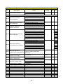
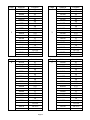
E510 Table of Contents
Chapter 0
0.1
Chapter 1
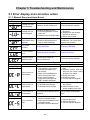
1.1
1.2
1.3
1.4
1.5
Chapter 2
2.1
2.2
2.3
Chapter 3
3.1
3.2
3.3
3.4
3.5
3.6
3.7
3.8
3.9
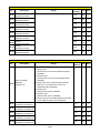
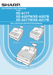
Preface
Preface
Safety Precautions
Before Power UP
During Power UP
Before Operation
During Operation
Inverter Disposal
Part Number Definition
Nameplate Data
Model Part Number
Standard Product Specification
Environment & Installation
Environment
Installation
3.2.1 Installation method
3.2.2 Installation space
3.2.3 De-rating curves
Wiring guidelines
3.3.1 Power Cables
3.3.2 Control Cable selection and Wiring
3.3.3 Wiring and EMC guidelines
3.3.4 Failure liability
3.3.5 Considerations for peripheral equipment
3.3.6 Ground connection
3.3.7 Inverter exterior
Specifications
3.4.1 Product Specifications
3.4.2 General Specifications
Standard wiring
3.5.1 Single phase
3.5.2 Single/ Three phase
3.5.3 Three phase
Terminal Description
3.6.1 Description of main circuit terminals
3.6.2 Control circuit terminal description
Outline Dimensions
3.7.1 IP20/NEMA1 dimensions
3.7.2 IP66/NEMA4 dimensions
EMC filter disconnection
The Dimension and Installation of Keypad
I
0-1
0-1
1-1
1-1
1-2
1-2
1-2
1-3
2-1
2-1
2-1
2-2
3-1
3-1
3-3
3-3
3-20
3-21
3-22
3-22
3-22
3-23
3-24
3-25
3-26
3-27
3-34
3-34
3-36
3-38
3-38
3-39
3-40
3-41
3-41
3-43
3-45
3-45
3-54
3-57
3-58
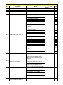
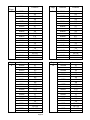
Chapter 4
4.1
4.2
4.3
4.4
Chapter 5
5.1
5.2
5.3
5.4
5.5
Chapter 6
6.1
6.2
6.3
6.4
6.5
Appendix 1
Appendix 2
Appendix 3
Appendix 4
Appendix 5
3.9.1 Description of dimension and installation
3.9.2 Description of Protective Stickers
Software Index
Keypad Description
4.1.1 Operator Panel Functions
4.1.2 Digital display Description
4.1.3 Digital display setup
4.1.4 Example of Keypad Operation
4.1.5 Operation Control
Programmable Parameter Groups
Parameter Function Description
Specification Description on Built-in PLC Function
4.4.1 Basic Instruction Set
4.4.2 Function of Basic Instructions
4.4.3 Application Instructions
Troubleshooting and Maintenance
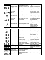
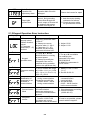
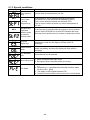
Error Display and Corrective Action
5.1.1 Manual Reset and Auto-Reset
5.1.2 Keypad Operation Error Instruction
5.1.3 Special conditions
General troubleshooting
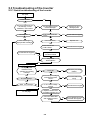
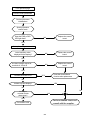
Troubleshooting of the Inverter
5.3.1 Quick troubleshooting of the Inverter
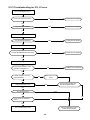
5.3.2 Troubleshooting for OC, OL error displays
5.3.3 Troubleshooting for OV, LV error
5.3.4 Motor not running
5.3.5 Motor Overheating
5.3.6 Motor runs unbalanced
Routine and periodic inspection
Maintenance
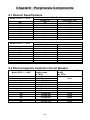
Peripheral Components
Reactor Specifications
Electromagnetic Contactor circuit breaker
Fuse Specification
Brake Resistor
Noise filter
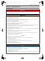
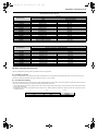
Instructions for UL
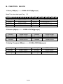
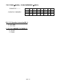
E510 Parameter Setting List
E510 MODBUS Communication protocol
E510 PLC Communication protocol
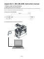
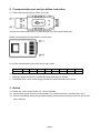
JN5-CM-USB instruction manual
II
3-58
3-60
4-1
4-1
4-1
4-2
4-4
4-5
4-7
4-8
4-27
4-78
4-78
4-79
4-80
5-1
5-1
5-1
5-3
5-4
5-5
5-6
5-6
5-8
5-9
5-10
5-11
5-12
5-12
5-14
6-1
6-1
6-1
6-2
6-2
6-3
App1-1
App2-1
App3-1
App4-1
App5-1
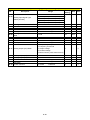
Chapter 0 Preface
0.1 Preface
To extend the performance of the product and ensure personnel safety, please read
this manual thoroughly before using the inverter. Should there be any problem in using the
product that cannot be solved with the information provided in the manual, contact Our’s
technical or sales representative who will be willing to help you.
※Precautions
The inverter is an electrical product. For your safety, there are symbols such as
“Danger”, “Caution” in this manual as a reminder to pay attention to safety instructions on
handling, installing, operating, and checking the inverter. Be sure to follow the instructions
for highest safety.
Danger
Indicates a potential hazard that could cause death or serious
personal injury if misused.
Caution
Indicates that the inverter or the mechanical system might be
damaged if misused.
Danger
¾
Risk of electric shock. The DC link capacitors remain charged for five
minutes after power has been removed. It is not permissible to open the
equipment until 5 minutes after the power has been removed.
¾
Do not make any connections when the inverter is powered on. Do not check
parts and signals on circuit boards during the inverter operation.
¾ Do not disassemble the inverter or modify any internal wires, circuits, or
parts.
¾ Ensure that the Inveter Ground terminal is connected correctly.
Caution
¾ Do not perform a voltage test on parts inside the inverter. High voltage can
destroy the semiconductor components.
¾ Do not connect T1, T2, and T3 terminals of the inverter to any AC input power
supply.
¾
CMOS ICs on the inverter’s main board are susceptible to static electricity. Do
not touch the main circuit board.
0-1
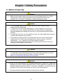
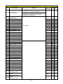
Chapter 1 Safety Precautions
1.1 Before Power Up
Danger
¾
Make sure the main circuit connections are correct Single phase L1(L),L3(N),
Three phase L1(L),L2,L3(N) are power-input terminals and must not be
mistaken for T1,T2 and T3. Otherwise, inverter damage can result.
Caution
¾ The line voltage applied must comply with the inverter’s specified input
voltage.(See the nameplate)
¾ To avoid the front cover from disengaging, or other damge do not carry the
inverter by its covers. Support the drive by the heat sink when transporting.
Improper handling can damage the inverter or injure personnel and should be
avoided.
¾ To avoid the risk of fire, do not install the inverter on a flammable object.Install on
nonflammable objects such as metal.
¾ This product provides the 24V for internal use only, do not use as the power
supply sources for other external components, such as sensors, electronic
components ... etc., otherwise it will cause adverse situation.
¾ When disconnecting the remote keypad, turn the power off first to avoid any
damage to the keypad or the inverter.
Caution
¾
¾
This product is sold subject to EN 61800-3 and EN 61800-5-1.
In a domestic environment this product may cause radio interference in which
case the user may be required to apply corrective measures.
Motor over temperature protection is not provided.
Caution
¾ Work on the device/system by unqualified personnel or failure to comply with
warnings can result in severe personal injury or serious damage to material. Only
suitably qualified personnel trained in the setup, installation, commissioning and
operation of the product should carry out work on the device/system.
¾ Only permanently-wired input power connections are allowed.
1-1
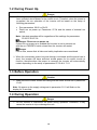
1.2 During Power Up
Danger
¾ When the momentary power loss is longer than 2 seconds, the inverter will not
have sufficient stored power for its control circuit. Therefore, when the power is
re-applied, the run operation of the inverter will be based on the setup of
following parameters:
•
•
Run parameters. 00-02 or 00-03.
Direct run on power up. Parameter. 07-04 and the status of external run
switch,
Note-: the start operation will be regardless of the settings for parameters
07-00/07-01/07-02.
Danger. Direct run on power up.
If direct run on power up is enabled and inverter is set to external run
with the run FWD/REV switch closed then the inverter will restart.
Danger
Prior to use, ensure that all risks and safety implications are considered.
¾ When the momentary power loss ride through is selected and the power loss is
short, the inverter will have sufficient stored power for its control circuits to
function, therefore,when the power is resumed the inverter will automatically
restart depending on the setup of parameters 07-00 & &- 7-01.
1.3 Before Operation
Caution
¾
Make sure the inverter model and rating are the same as that set in parameter
13-00.
Note :On power up the supply voltage set in parameter 01-01 will flash on the
display for 2 seconds.
1.4 During Operation
Danger
¾
Do not connect or disconnect the motor during operation. Otherwise, It may
cause the inverter to trip or damage the unit.
1-2
Danger
¾ To avoid electric shock, do not take the front cover off while power is on.
¾ The motor will restart automatically after stop when auto-restart function is
enabled. In this case, care must be taken while working around the drive and
associated equipment .
¾ The operation of the stop switch is different than that of the emergency stop
switch. The stop switch has to be activated to be effective. Emergency stop has
to be de-activated to become effective.
Caution
¾ Do not touch heat radiating components such as heat sinks and brake
resistors.
¾ The inverter can drive the motor from low speed to high speed. Verify the
allowable speed ranges of the motor and the associated machinery.
¾ Risk of electric shock. The DC link capacitors remain charged for five minutes
after power has been removed. It is not permissible to open the equipment until 5
minutes after the power has been removed.
Caution
¾
The Inverter should be used in environments with temperature range from
(14-104°F) or (-10 to 50°C)* and relative humidity of 95%.
* –10 ~ 50℃ (without dustproof cover/ paster),
–10 ~ 40℃ (with dustproof cover/ paster).
Danger
¾ Make sure that the power is switched off before disassembling or checking any
components.
1.5 Inverter Disposal
Caution
Please dispose of this unit with care as an industrial waste and according to your
required local regulations.
¾ The capacitors of inverter main circuit and printed circuit board are considered as
hazardous waste and must not be burnt.
¾
The plastic enclosure and parts of the inverter such as the cover board will
release harmful gases if burnt.
1-3
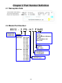
Chapter 2 Part Number Definition
2.1 Nameplate Data
Inverter Model & Motor Rating
Input Power Specifications
Output Power Specifications
(P/N Barcode)
(S/N Barcode)
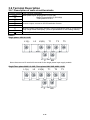
2.2 Model Part Number
E510 - 2 P5 - H 1 F N4S
Supply voltage
2:200V Class
4:400V Class
Horsepower
200V Class P5:
01:
02:
03:
05:
08:
10:
15:
20:
400V Class 01:
02:
03:
05:
08:
10:
15:
20:
25:
Structure:
N4S: IP66/Built-in VR+Switch
N4:IP66
N4R:IP66/Built-in VR
Blank:IP20
0.5 HP
1 HP
2 HP
3 HP
5 HP
8 HP
10 HP
15 HP
20 HP
1 HP
2 HP
3 HP
5 HP
8 HP
10 HP
15 HP
20 HP
25 HP
EMC Filter
F :Built-in
Blank:None
Power supply
1: Single phase
3: Three phase
Specification
H:Standard Type
2-1
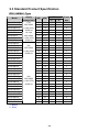
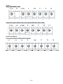
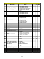
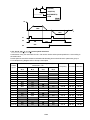
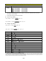
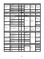
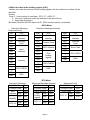
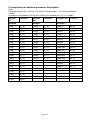
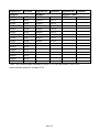
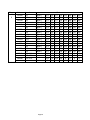
2.3 Standard Product Specification
IP20 / NEMA 1 Type
Model
E510-2P5-H1F
E510-201-H1F
E510-202-H1F
E510-203-H1F
E510-2P5-H
E510-201-H
E510-202-H
E510-203-H
E510-202-H3
E510-205-H3
E510-208-H3
E510-210-H3
E510-215-H3
E510-220-H3
E510-401-H3F
E510-401-H3
E510-402-H3F
E510-402-H3
E510-403-H3F
E510-403-H3
E510-405-H3F
E510-405-H3
E510-408-H3F
E510-408-H3
E510-410-H3F
E510-410-H3
E510-415-H3F
E510-415-H3
E510-420-H3F
E510-420-H3
E510-425-H3F
E510-425-H3
Supply
voltage (Vac)
1 ph,
200~240V
(+10%-15%)
50/60 Hz
1 & 3 ph,
200~240V
(+10%-15%)
50/60 Hz
3ph,
200~240V
(+10%-15%)
50/60 Hz
3ph,
380~480V
(+10%-15%)
50/60 Hz
(HP)
(KW)
0.5
1
2
3
0.5
1
2
3
2
5
7.5
10
15
20
1
1
2
2
3
3
5
5
7.5
7.5
10
10
15
15
20
20
25
25
0.4
0.75
1.5
2.2
0.4
0.75
1.5
2.2
1.5
3.7
5.5
7.5
11
15
0.75
0.75
1.5
1.5
2.2
2.2
3.7
3.7
5.5
5.5
7.5
7.5
11
11
15
15
18.5
18.5
Filter
V
◎
◎
◎
◎
X
◎
◎
◎
◎
◎
◎
◎
◎
◎
◎
◎
◎
◎
◎
◎
◎
◎
◎
◎
◎
◎
◎
◎
◎
◎
◎
◎
◎
V : Built-in
X : None
2-2
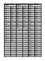
Frame
Size
1
1
2
2
1
1
2
2
1
2
3
3
4
4
1
1
1
1
2
2
2
2
3
3
3
3
3
3
4
4
4
4
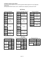
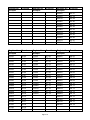
IP66 / NEMA 4X Type
Model
Supply
voltage
(Vac)
HP
(KW)
Filter
V
X
VR
V
Switch
X
V
X
Frame
Size
1 ph
200~240V
+10%-15%
50/60Hz
0.5
0.4
◎
◎
◎
1
1
0.75
◎
◎
◎
1
2
1.5
◎
◎
◎
2
3
2.2
◎
◎
◎
2
1 & 3 ph
200~240V
+10%-15%
50/60Hz
0.5
0.4
◎
◎
◎
1
1
0.75
◎
◎
◎
1
2
1.5
◎
◎
◎
2
3
2.2
◎
◎
◎
2
5
3.7
◎
◎
◎
2
7.5
5.5
◎
◎
◎
3
10
7.5
◎
◎
◎
3
15
11
◎
◎
◎
3
E510-220-H3N4
20
15
◎
◎
◎
3
E510-401-H3FN4S
1
0.75
E510-401-H3N4
1
0.75
E510-402-H3FN4S
2
1.5
E510-402-H3N4
2
1.5
E510-403-H3FN4S
3
2.2
E510-403-H3N4
3
2.2
5
3.7
5
3.7
7.5
5.5
7.5
5.5
E510-410-H3FN4S
10
7.5
E510-410-H3N4
10
7.5
E510-415-H3FN4S
15
11
E510-415-H3N4
15
11
◎
◎
◎
3
E510-420-H3N4
20
15
◎
◎
◎
3
E510-425-H3N4
25
18.5
◎
◎
◎
3
E510-2P5-H1FN4S
E510-201-H1FN4S
E510-202-H1FN4S
E510-203-H1FN4S
E510-2P5-HN4R
E510-201-HN4R
E510-202-HN4R
E510-203-HN4R
E510-205-H3N4
E510-208-H3N4
E510-210-H3N4
E510-215-H3N4
E510-405-H3FN4S
E510-405-H3N4
E510-408-H3FN4S
E510-408-H3N4
3 ph
200~240V
+10%-15%
50/60Hz
3 ph
380~480V
+10%-15%
50/60Hz
V : Built-in
X : None
2-3
◎
◎
◎
◎
◎
◎
◎
◎
◎
◎
◎
◎
◎
◎
◎
◎
◎
◎
2
3
◎
◎
◎
2
2
◎
◎
◎
◎
◎
1
2
◎
◎
◎
◎
◎
1
1
◎
◎
◎
◎
◎
◎
1
3
3
◎
◎
3
3
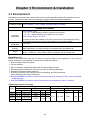
Chapter 3 Environment & Installation
3.1 Environment
Installation environment has a direct effect on the correct operation and the life expectancy of the
inverter, Install the inverter in an environment complying with the following conditions:
Protection
Protection class IP20 / NEMA 1 / IP66 / NEMA 4X (Depending on models)
Suitable Environment
Operating
temperature
Storage
temperature
Relative
Humidity
Shock
IP20 / NEMA 1 type:
–10 ~ 50℃ inside distributor (without dustproof cover/ paster),
–10 ~ 40℃ outside distributor (with dustproof cover/ paster).
IP66 / NEMA 4X type: -10~50°C
If several inverters are installed in the same control panel, ensure adequate spacing
and provide the necessary cooling and ventilation for successful operation.
-20~60°C
Max 95% (without condensation)
Notice prevention of inverter freezing up.(Compliance with IEC 60068-2-78).
1G.
(9.8m/s²)
for 20Hz and below.
0.6G (5.88m/s²) from 20Hz to 50Hz (Compliance with IEC 60068-2-6)
Installation site
Install in an environment that will not have an adverse effect on the operation of the unit and
ensure that there is no exposure to areas such as that listed below:¾ Direct sunlight, Rain or moisture.
¾ Oil mist and salt
¾ Dust, lint fibbers, small metal filings and Corrosive liquid and gas.
¾ Electromagnetic interference from sources such as welding equipment.
¾ Radioactive and flammable materials.
¾ Excessive vibration from machines such as stamping, punching machines.
add a vibration-proof pads if necessary.
¾ Non-IP66/NEMA4X protection class drive should prevent the invasion of dust, cotton, and small
metal shavings.
¾ Non-IP66/NAME4X protection class drive should prevent exposure to rain or moisture.
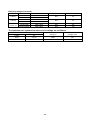
Tightening torque for terminals
TM1
Model
Cable Size
Tightening torque
AWG
mm²
kgf.cm
Ibf.in Nm
10.20
Frame1 20~12
0.52~3.33
0.006 1.0
18.35
Frame2 18~8
0.81~8.37
0.010 1.8
Frame3
Frame4
14~6
4~3
2.08~13.30
21.15~26.67
24.47
0.014
3-1
2.4
Cable Size
AWG
mm²
26~14
0.13~2.08
TM2
Tightening torque
kgf.cm
Ibf.in Nm
8.16
0.005
0.8
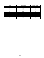
Electrical ratings of terminals
Model
Frame1
Frame2
Frame 3/4
Horsepower
0.5/1
1/2
2/3/5
3/5
7.5/10/15/20
7.5/10/15/20/25
Power Specification
200V~240V
380V~480V
200V~240V
380V~480V
200V~240V
380V~480V
Voltage (Volt)
Current(A)
600
20
600
45
600
600
65
100
The maximum rms symmetrical short circuit ratings are as follows.
Device Rating
voltage
220V
440V
HP
0.5~20
1~25
3-2
Short circuit
Rating(A)
Maximum
Voltage (Volt)
5000
5000
240
480
3.2 Installation
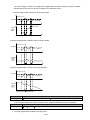
3.2.1 Installation method
3.2.1.1 IP20 / NEMA 1 standard installaion
(a)Single/Three phase: 200V 0.5~1HP; Single phase: 200V 0.5~1HP; Three phase: 200V 2HP; 400V
1~2HP;
Frame1
Frame1(NEMA1)
Screw M4
Screw M4
Screw M4
Screw M4
(b)Single/Three phase: 200V 2~3HP; Single phase: 200V 2~3HP; Three phase: 200V 5HP; 400V 3~5HP;
Frame2
Screw M4
Screw M4
Frame2(NEMA1)
Screw M4
Screw M4
3-3
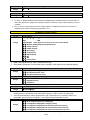
(c)Three phase: 200V 7.5~10HP; 400V 7.5~15HP;
Frame3
Screw M4
Screw M4
Frame3(NEMA1)
Screw M4
Screw M4
3-4
(d)Three phase: 200V 15~20HP; 400V 20~25HP;
Frame4
Screw M5
Screw M5
Frame4(NEMA1)
Screw M5
Screw M5
3-5
(e) Three phase: 400V 20~25HP; (With Fliter Models)
Frame4
Screw M5
Screw M5
3-6
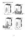
3.2.1.2 IP66/NEMA 4X standard installaion
(a)Single/Three phase : 200V 0.5~1HP ; Single phase : 200V 0.5~1HP; Three phase : 200V 2HP ;
400V 1~2HP ;
Screw M5
Screw M5
(b)Single / Three phase: 200V 2~3HP ; Single phase : 200V 2~3HP ; Three phase : 200V5HP ; 400V
3~5HP ;
Screw M6
Screw M6
3-7
(c) Three phase : 200V 8~20HP ; 400V 8~25HP ;
Screw M6
Screw M6
3-8
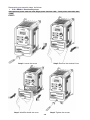
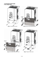
Disassembly and assembly steps, As follows:
¾ IP20 / NEMA 1 Disassembly steps
(a)Single/Three phase: 200V 0.5~1HP; Single phase: 200V 0.5~1HP; Three phase: 200V 2HP; 400V
1~2HP;
Frame1
Step1: Loosen the screw
Step2: Remove the terminal cover
Step3: Wire&Re-install the cover
Step4: Tighten the screws
3-9
Frame 1(NEMA1)
Step1: Loosen the screw
Step2: Remove the terminal cover
Step3: Wire&Re-install the cover
Step4: Tighten the screws
3-10
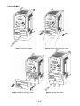
(b)Single/Three phase: 200V 2~3HP; Single phase: 200V 2~3HP; Three phase: 200V 5HP; 400V 3~5HP;
Frame 2
Step1: Loosen the screws
Step2: Remove the terminal cover
Step3: Wirie&Re-install the cover
Step4: Tighten the screws
3-11
Frame 2(NEMA1)
Step1: Loosen the screws
Step2: Remove the terminal cover
Step3: Wire&Re-install the cover
Step4: Tighten the screws
3-12
(c)Three phase: 200V 7.5~10HP; 400V 7.5~15HP;
Frame 3
Step1: Loosen the screws
Step3: Wirie&Re-install the cover
Step2: Remove the terminal cover
Step4: Tighten the screws
3-13
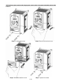
Frame 3(NEMA1)
Step1: Loosen the screws
Step2: Remove the terminal cover
Step3: Wirie&Re-install the cover
Step4: Tighten the screws
3-14
(d)Three phase: 200V 15~20HP; 400V 20~25HP;
Frame 4
Step1: Loosen the screws
Step2: Remove the terminal cover
Step3: Wirie&Re-install the cover
Step4: Tighten the screws
3-15
Frame 4(NEMA1)
Step1: Loosen the screws
Step2: Remove the terminal cover
Step3: Wirie&Re-install the cover
Step4: Tighten the screws
3-16
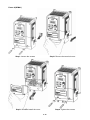
(e) Three phase: 400V 20~25HP;
Frame 4(With Filter)
STEP1
STEP2
Step1: Loosen the screws
Step2: Remove the terminal cover
STEP2
STEP1
Step3: Wirie&Re-install the cover
Step4: Tighten the screws
3-17
¾
IP66/NEMA 4X
Disassembly steps
Step 1: Loosen the cover screws, place the cover on the left side of the machine
without removing
Steps 2: Use a flat screwdriver to remove the three bushes in the wiring port, connect
the attached waterproof cable connector plug and tighten.
(Note : Waterproof rubber gasket is placed outside the machine)
3-18
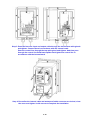
Step 3: Pass the four-wire input and output cable through the two bottom cable glands
and tighten. Connect them in accordance with the internal mark.
Pass the control line through the top cable gland and tighten. And then pass
through the control line fixed beam splitter and tighten the control line in
accordance with the internal mark.
Step 4: Reconfirm the internal cable and waterproof cable connector are locked, close
the cover and tighten it with screws to complete the installation
3-19
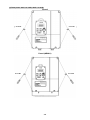
3.2.2 Installation space
Provide sufficient air circulation space for cooling as shown in examples below.
Install the Inverter on surfaces that provide good heat dissipation,
Single unit Installation
Install the inverter verticality to obtain effective cooling
Fan
CONTROL
12cm
PANEL
Hz/RPM
FWD
REV
FWD
REV
DSP
FUN
RESET
READ
ENTER
FUN
FREQ. SET
5cm
RUN
5cm
STOP
DANGER
Cut-off the power and wait for 5 minutes before inspecting
components.
CAUTION
See manual before operation.
12cm
Front view
Side view
Side by side Installation
Provide the necessary physical space and cooling based on the ambient temperature and the heat
loss in the panel
Extract fan
CONTROL
PANEL
Hz/RPM
FWD
REV
FWD
REV
DSP
FUN
RESET
READ
ENTER
FUN
Hz/RPM
5cm
FREQ. SET
RUN
STOP
DANGER
CAUTION
Note:“
DSP
FUN
RESET
READ
ENTER
FREQ. SET
DANGER
Cut-off the power and wait for 5 minutes before inspecting
components.
See manual before operation.
“ represets Fan.
3-20
FUN
STOP
CAUTION
See manual before operation.
REV
FWD
REV
RUN
Cut-off the power and wait for 5 minutes before inspecting
components.
FWD
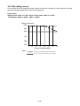
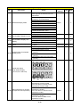
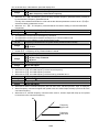
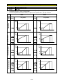
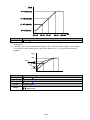
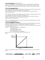
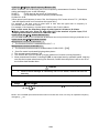
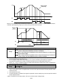
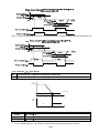
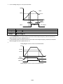
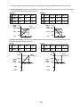
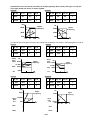
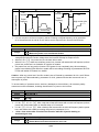
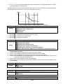
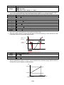
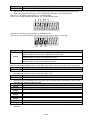
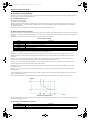
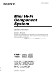
3.2.3 De-rating curves
Curves below show the applicable output current de-rate due to setting of carrier frequency and the
ambient operating temperatures of 40 and 50 degrees C .
Frame1/2/3/4
(Single phase: 200V: 0.5~3HP; Single /Three phase: 200V: 0.5~3HP;
Three phase: 200V: 2~20HP 400V: 1~25HP)
Rating Current(In)
100%
90%
85%
70%
60%
50%
2
4
6
8
10
12
14
16
Carrier Frequency(KHz)
Note:
De-rate curve for ambient temperature of 40 degree C.
De-rate curve for ambient temperature of 50 degree C.
3-21
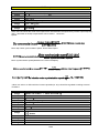
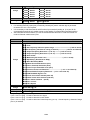
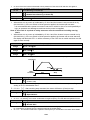
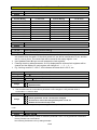
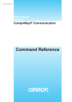
3.3 Wiring Guidelines
3.3.1 Power Cables
Supply power cable must be connected to TM1 terminal block, terminals L1(L), L2, L3(N).
L1(L) and L3(N) for single phase 230V supply.
Motor cable must be connected to TM1 terminals. T1, T2, T3.
Warning:- Connection of supply line cable to terminals T1,T2, T3 will result in serious
damage to the drive components.
Example power connections: Inverter with dedicated power line.
Power
MCCB
Inverter
IM
¾ Install a Supply RFI filter or Isolation transformer when the power source is shared with other
high power electrical equipment as shown below.
MCCB
Power
Power
MCCB
Inverter
RFI
Filter
Inverter
IM
IM
Insulation transformer
Machine
Machine
3.3.2 Control Cable selection and Wiring
Control cables should be connected to terminal block TM2.
Choose power & Control cables according to the following criteria:¾ Use copper wires with correct diameter and temperature rating of 65/70°C.
¾ Minimum cable voltage rating for 200V type inverters should be 300VAC. Minimum cable
voltage rating for 400V type inverters should be 600VAC.
¾ Route all cables away from other high voltage or high current power lines to reduce
interference effects.
¾ Use a twisted pair shielded cable and connect the shield (screen) wire to the ground terminal at
the inverter end only. Cable length should not exceed 50 meters.
Shielding sheath
Protective covering
Do not connect this end
Connect the shield to
Inverter ground terminal
3-22
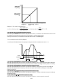
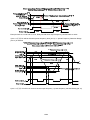
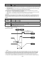
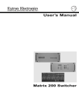
3.3.3 Wiring and EMC guidelines
For effective interference suppression, do not route power and control cables in the same
conduit or trunking.
To prevent radiated noise, motor cable should be put in a metal Conduit. Alternatively an
armored or shielded type motor cable should be used.
For effective suppression of noise emissions the cable armor or shield must be grounded
at both ends to the motor and the inverter ground. These connections should be as short
as possible.
Motor cable and signal lines of other control equipment should be at the least 30 cm apart.
E510 has a built in Class “A” EMC filter to first Environment Restricted. (Category C2).
Typical Wiring.
L1(L)
L3(N)
E
L1(L)
L3(N)
1.Protective Earth Conductor.
Conductor size for enclosure &
Back plate must comply with the local
electrical standards. Min 10mm².
2.Back plate. Galvanised steel (Unpainted).
3.Ferrite core / Output reactor
ferrite cores can be used to reduce
radiated noise due to long motor cables.
If ferrite core is used loop motor wires, 3
times round the core. Install core as close
to the inverter as possible
Output reactors provide additional
benefit of reducing dv/dt for protection of
motor windings.
4.Metal Cable clamp. no more than 150mm
from the inverter.
Note: If no enclosure & back plate is
used then connect the cable shield by a
good 360 degree termination to the
Inverter output terminal E.
5.Screened (Shielded four core cable).
6.Separate Protective Earth wire, routed
outside motor cable separated be at least
100mm.
Note:- this is the preferred method
specially for large output cables and long
length.
Multi-core screened (3 core & protective
earth) can be used for small power and
short length.
7.Connect the cable shield by a good
360º termination and connect to the motor
protective earth terminal.
This link must be as short as possible.
8.Motor Earth terminal(Protective Earth).
3-23
3.3.4 Failure liability
¾ Teco bears no responsibility for any failures or damaged caused to the inverter if the
recommendations in this instruction manual have not been followed specifically points listed
below,
¾ If a correctly rated Fuse or Circuit breaker has not been installed between the power
source and the inverter.
¾ If a magnetic contactor, a phase capacitor, burst absorber and LC or RC circuits have been
connected between the inverter and the motor.
¾ If an incorrectly rated three-phase squirrel cage induction motor has been used
Note:
When one inverter is driving several motors, the total current of all motors running
simultaneously must be less than the rated current of the inverter, and each motor has to be
equipped with a correctly rated thermal overload relay.
※1. “Only Intended For Use In A Pollution Degree 2 Environment” or equivalent.
※2. Since there is no over speed protection there will be no liablity due to overspeed damage.
3-24
3.3.5 Considerations for peripheral equipment
Power
Circuit
Breaker
& RCD
Magnetic
contactor
AC reactor for
power quality
improvement
Input noise
filter
Inverter
Motor
(
Grounding
Ensure that the supply voltage is correct.
A molded-case circuit breaker or fused disconnect
must be installed between the AC source and the
inverter
Use a molded-case circuit breaker that conforms
to the rated voltage and current of the inverter.
Do not use the circuit breaker as the run/stop
switch for the inverter.
Residual Current Circuit Breaker(RCD)
Current setting should be 200mA or above and the
operating time at 0.1 second or longer to prevent
malfunctions.
Normally a magnetic contactor is not needed.
A contactor can be used to perform functions such
as external control and auto restart after power
failure.
Do not use the magnetic contactor as the run/stop
switch of the inverter.
When a 200V/400V inverter with rating below
15KW is connected to a high capacity power
source (600KVA or above) then an AC reactor can
be connected for power factor improvement and
reducing harmonics.
E510 inverter has a built-in filter to Class “A” first
Environment. (CategoryC2)
To satisfy the required EMC regulations for your
specific application you may require an additional
EMC filter.
Connect the single phase power to Terminals,
L1(L) & L3(N).
Warning! Connecting the input terminals T1, T2,
and T3 to AC input power will damage the inverter.
Output terminals T1, T2, and T3 are connected to
U, V, and W terminals of the motor.
To reverse the motor rotation direction just swap
any two wires at terminals T1, T2, and T3.
Ground the Inverter and motor correctly.
Ground Resistance for 200V power<100 Ohms.
Ground Resistance for 400V power<10 Ohms
Three-phase induction motor. Voltage drop on
motor due to long cable can be calculated.
Volts drop should be < 10%.
Phase-to-phase voltage drop (V) =
3 ×resistance of wire (Ω/km)×length of
line(m)×current×10-3
3-25
3.3.6 Ground connection
Inverter ground terminal must be connected to installation ground correctly and
according to the required local wiring regulations.
¾ Ground cable size must be according to the required local wiring
regulations. Ground connection should be as short as possible.
¾ Do not share the ground of the inverter with other high current loads (Welding machine, high
power motors). Ground each unit separately.
¾ Ensure that all ground terminals and connections are secure
¾
Do not make ground loops when several inverters share a common ground point.
Note: Please leave at least 5cm while installing inverter side by side in order to provide enough
cooling space.
(a)
Correct
(b)
Correct
3-26
(c) Incorrect
3.3.7 Inverter exterior
3.3.7.1 IP20/NEMA 1 exterior
(a) Single/Three phase: 200V 0.5~1HP; Single phase: 200V 0.5~1HP;
2HP; 400V 1~2HP;
E510-Frame 1
E510-Frame 1(NEMA1)
3-27
Three phase: 200V
(b) Single/Three phase: 200V 2~3HP; Single phase: 200V 2~3HP; Three phase: 200V 5HP;
400V 3~5HP;
E510-Frame2
E510-Frame2(NEMA1)
3-28
(c) Three phase: 200V 7.5~10HP; 400V 7.5~15HP;
E510-Frame 3
E510-Frame 3(NEMA1)
3-29
(d) Three phase: 200V 15~20HP; 400V 20~25HP;
E510-Frame 4
E510-Frame 4(NEMA1)
3-30
(e) Three phase: 400V 20~25HP;
E510-Frame 4 (With Filter)
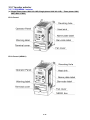
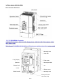
3.3.7.2 IP66/NEMA 4X exterior
(a) Single/Three phase : 200V 0.5~1HP ; Single phase : 200V 0.5~1HP ; Three phase : 200V
2HP ; 400V 1~2HP
E510-Frame 1(IP66/NEMA 4X With/Without VR and power switches depending on the model)
Mounting hole
Heat sink
7-seg Display
Front cover
Operator
Name plate label
Voltage label
VR
Screw
Bottom cover
Switch handle
Mounting hole
Power switch
waterproof cable
connector plug
3-31
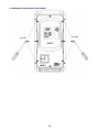
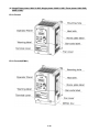
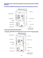
(b) Single/Three phase : 200V 2~3HP ; Single phase : 200V 2~3HP;Three phase : 200V5HP ;
400V 3~5HP
E510-Frame 2 (IP66/NEMA 4X With/Without knobs and switches depending on the model)
Heat sink
Mounting hole
7-seg Display
Bottom cover
Operator
VR
Voltage label
Power switch
Front cover
Screw
Switch handle
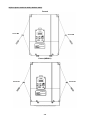
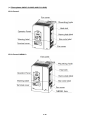
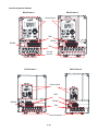
(c) Three phase : 200V 8~20HP ; 400V 8~25HP
waterproof cable
connector plug
E510-Frame 3 (IP66/NEMA 4X With/Without knobs and switches depending on the model)
Mounting hole
Heat sink
Front cover
Bottom cover
7-seg Display
Operator
VR
Voltage label
Power switch
Screw
Switch handle
waterproof cable
connector plug
3-32
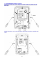
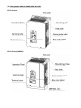
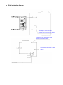
Interior Structure Outlook
E510-Frame 1
E510-Frame 2
Control Panel
TM2
200V 0.75kW
RS485
400V 3.7kW
RS485
TM1
Ground
termina
E510-Frame 3
E510-Frame 4
Control Panel
TM2
RS485
RS485
400V 5.5kW
400V 15kW
TM1
Ground terminal
3-33
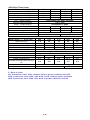
3.4 Specifications
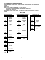
3.4.1 Product Specifications
200V Class:Single phase
Model:E510-□□□- H1F(N4)(S)
Horse power (HP)
Suitable motor capacity (KW)
Rated output current (A)
Rated capacity (KVA)
Input voltage range(V)
Allowable voltage fluctuation
Output voltage range(V)
Input current (A)*
Inverter net weight (KG)
Allowable momentary power loss time (S)
Enclosure
Frame Size
2P5
0.5
0.4
3.1
1.2
201
202
203
1
2
3
0.75
1.5
2.2
4.5
7.5
10.5
1.7
2.90
4.00
Single Phase:200~240V,50/60HZ
+10 %-15%
Three phase: 0~240V
8.5
12
16
23.9
1.65
1.65
2.5
2.5
2.0
2.0
2.0
2.0
I P 20 /N E MA 1 / I P6 6 /N E MA 4X( D ep en d in g on m od e ls)
1
2
200V Class:Single/Three phase
Model:E510-□□□- H(N4R)
Horse power (HP)
Suitable motor capacity (KW)
Rated output current (A)
Rated capacity (KVA)
Input voltage range(V)
Allowable voltage fluctuation
Output voltage range(V)
Input current (A)*
Inverter net weight (KG)
Allowable momentary power loss time (S)
Enclosure
Frame Size
2P5
201
202
203
0.5
1
2
3
0.4
0.75
1.5
2.2
3.1
4.5
7.5
10.5
1.2
1.7
2.90
4.00
Single/Three Phase:200~240V, 50/60HZ
+10 %-15%
Three phase: 0~240V
8.5/4.5
12/6.5
16/11
23.9/12.5
1.6
1.6
2.5
2.5
2.0
2.0
2.0
2.0
I P 20 /N E MA 1 / I P6 6 /N E MA 4X( D ep en d in g on m od e ls)
1
2
200VClass:Three phase
Model: E510-□□□- H3(N4)
202
205
208
210
215
220
Suitable motor capacity (KW)
2
1.5
5
3.7
7.5
5.5
10
7.5
15
11
20
15
Rated output current (A)
7.5
17.5
26
35
48
64
Rated capacity (KVA)
2.9
6.7
9.9
13.3
20.6
27.4
Horse power (HP)
Input voltage range(V)
Allowable voltage fluctuation
Output voltage range(V)
Input current (A)*
11
1.6
2.0
Three phase :200~240V,50/60HZ
+10 %-15%
Three phase: 0~240V
20.5
33
42
57
2.5
6.5
6.5
10.1
2.0
2.0
2.0
2.0
70
10.4
2.0
Inverter net weight (KG)
Allowable momentary power loss time (S)
Enclosure
I P 20 /N E MA 1 / I P6 6 /N E MA 4X( D ep en d in g on m od e ls)
1
2
3
4
Frame Size
*The input current is calculated value at full rated output current.
3-34
400VClass:Three phase
Model:E510-□□□- H3(F)(N4)(S)
Horse power (HP)
Suitable motor capacity (KW)
Rated output current (A)
Rated capacity (KVA)
Input voltage range(V)
Allowable voltage fluctuation
Output voltage range(V)
Input current (A)*
Inverter net weight (KG)
Allowable momentary power loss time (S)
Enclosure
Frame Size
Model:E510-□□□- H3(F)(N4)
Horse power (HP)
Suitable motor capacity (KW)
Rated output current (A)
Rated capacity (KVA)
Input voltage range(V)
Allowable voltage fluctuation
Output voltage range(V)
Input current (A)*
Inverter net weight (KG)
Allowable momentary power loss time
(S)
Enclosure
Frame Size
401
1
0.75
2.3
1.7
402
403
405
2
3
5
1.5
2.2
3.7
3.8
5.2
8.8
2.9
4.0
6.7
Three phase:380~480V,50/60HZ
+10 %-15%
Three phase:0~480V
4.2
5.6
7.3
11.6
1.7
1.7
2.5
2.5
2.0
2.0
2.0
2.0
I P 20 /N E MA 1 / I P6 6 /N E MA 4X( D ep en d in g on m od e ls)
1
408
7.5
5.5
13.0
9.9
17
6.7
2
410
415
420
10
15
20
7.5
11
15
17.5
24
32
13.3
19.1
27.4
Three phase:380~480V,50/60HZ
+10 %-15%
Three phase: 0~480V
23
31
38
6.7
6.7
13.7
2.0
2.0
2.0
425
25
18.5
40
34
48
13.7
2.0
2.0
I P 20 /N E MA 1 / I P6 6 /N E MA 4X( D ep en d in g on m od e ls)
3
*The input current is calculated value at full rated output current.
F: Built-in filter
N4: Protection class IP66, without built-in power switches and VR.
N4R: Protection class IP66, with built-in VR, without power switches
N4S: Protection class IP66, with built-in power switches and VR
3-35
4
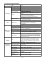
3.4.2 General Specifications
Item
Control Mode
Output Frequency
Starting Torque
Speed Control Range
Setting resolution
Frequency
Setting
Frequency limit
Run
Operation set
V / F curve setting
Carrier frequency
Main Control
Features
Acceleration and
deceleration control
Multifunction input
Multifunction output
Multifunction analog
output
Main features
Display
LED
LED Status Indicator
Protective
Functions
Overload Protection
E510
V/F Control, Vector Control
0.01~650.00Hz
150%/1Hz(Vector)
1:50
Digital input: 0.01Hz
Analog input:0.06Hz/60Hz
Keypad:Set directly with▲▼ keys or the VR on the
keypad
External Input Terminlas:
AI1(0/2~10V), AI2(0/4~20mA)input
Multifunction input up/down function(Group3)
Setting frequency by communication method.
Lower and upper frequency limits
3 skip frequency settings.
Keypad run, stop button
External terminals:
Multi- operation-mode2 / 3 wire selection
Jog operation
Run signal by communication method.
18 fixed curves and one customized curve
1~16KHz
2 off Acc / dec time parameters.
4 off S curve parameters.
29 functions (refer to description on group3)
21 functions (refer to description on group3)
5 functions (refer to description on group3)
Overload Detection,16 preset
speeds,Auto-run,Acc/Dec Switch (2 Stages),Main/Alt
run Command select,Main/Alt Frequency Command
select,PID control, torque boost, V/F start Frequency,
Fault reset, Firemode.
Display :parameter / parameter value / frequency /
line speed / DC voltage / output voltage / output
current / PID feedback / input and output terminal
status / Heat sink temperature / Program Version /
Fault Log.
Run / Stop / Forward / Reverse ,and etc.
The relays to protect the motor and the inverter.
(150%/1min)
Over voltage
·220V: >410V ,380V: >820V
Under Voltage
·220V: <190V , 380V: <380V
Momentary Power
Loss Restart
Inverter auto-restart after a momentary power loss.
Stall Prevention
Stall prevention for Acceleration/ Deceleration/
Operation.
Short-circuit output
terminal
Electronic Circuit Protection
Grounding Fault
Electronic Circuit Protection
3-36
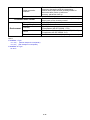
Protection for overheating of heat sink,The carrier
frequency decreasing with the temperature
Other protection
function,fault output,reverse prohibit,prohibit for
features
direct start after power up and error
recovery ,parameter lock up
All frames include brake transistor
Standard built-in RS485 communication (Modbus),
Communication control
One to one or One to many control.
-10~50℃ (Note1)
Operating temperature
-20~60℃
Storage temperature
95% RH or less (no condensation)
Humidity
(Compliance
with IEC 60068 - 2-78)
Environment
20Hz or less 1G(9.8m/s²)20~50Hz 0.6G(5.88m/s²)
Shock
(Compliance with IEC 60068 - 2-6)
Protection class
IP20/NEMA1/IP66/NEMA4X ( Depending on models)
Note1:
IP20/NEMA 1 Type:
–10 ~ 50℃ (without dustproof cover/paster)
–10 ~40℃ (with dustproof cover/paster)
IP66/NEMA 4X Type :
-10~50°C
3-37
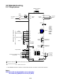
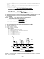
3.5 Standard wiring
3.5.1 Single phase:
Braking resistor
(Option)
P
Main
Switch
Fuse
L1( L)
AC Power
source
L3(N)
BR
T1
Inverter
output T2
Power
input
M
Induction
Motor
T3
E
Ground
Multifunction Input Terminals
CON2
FWD
(Run/Stop)
S1
REV (Run/Stop)
S2
RS485
Pin 1 to Pin 8
1:Data+
2:Data3:Data+
4:RXD0
5:TXD0
6:Data7:5V
8:GND
S3
R1A
S4
Speed Control
S5
Reset
Relay
Output
S6
R1B 250 VAC/1A
(30VDC/1A)
R1C
COM (NPN)
+ 24V(PNP)
R2A
E
Output disable
+
SF
*1
SG
NPN AI1 AI2
J
J
J
P
P P
1
2 3
PNP AV1 AV2
10V
0 ~10V
Frequency indicator device
or PID input
AI1
0~20mA
P
AI2
P
- AGND
Indicates shield wire
Shows main circuit
Relay
Output
E
R2B
AO
250 VAC/1A
(30VDC/1A)
+
AO
AGND
-
E
P Indicates twisted-pair shield wire
Shows control circuit
*1: JP1:NPN/PNP selection, JP2:AI1 0~10V/0~20mA selection, JP3:AI2 0~10V/0~20mA selection
Model:
200V:E510-2P5-H1(F)(N4S)/E510-201-H1(F)(N4S)/
E510-202-H1(F)(N4S)/E510-203-H1(F) (N4S)
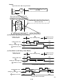
3-38
Frequency
Indicator
0~10VDC
3.5.2 Single /Three phase:
Model:
200V: E510-2P5-H(N4R)/ E510-201-H(N4R)/ E510-202-H(N4R)/ E510-203-H(N4R)
3-39
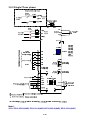
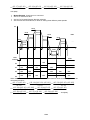
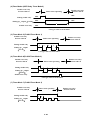
3.5.3 Three phase
Braking resistor
(Option)
P
Main
Switch
Fuse
BR
T1
L1
AC Power
source
L2
Power
input
Inverter
output T2
M
T3
L3
E
Ground
Multifunction Input Terminals
CON2
FWD
(Run/Stop)
S1
REV (Run/Stop)
S2
RS485
Pin 1 to Pin 8
S3
S5
Reset
1:Data+
2:Data3:Data+
4:RXD0
5:TXD0
6:Data7:5V
8:GND
R1A
S4
Speed Control
Induction
Motor
Relay
Output
S6
R1B 250 VAC/1A
(30VDC/1A)
R1C
COM (NPN)
+ 24V(PNP)
R2A
E
Output Disable
+
0 ~10V
Frequency indicator device
or PID input
P
SF
*1
SG
NPN AI1 AI2
J
J
J
P
P P
1
2 3
PNP AV1 AV2
10V
AI1
0~20mA
AI2
P
- AGND
Indicates shield wire
Shows main circuit
Relay
Output
R2B
AO
250 VAC/1A
(30VDC/1A)
+
AO
AGND
-
Frequency
Indicator
0~10VDC
E
E
P Indicates twisted-pair shield wire
Shows control circuit
*1: JP1:NPN/PNP selection, JP2:AI1 0~10V/0~20mA selection, JP3:AI2 0~10V/0~20mA selection
Model:
200V:E510-202-H3(N4)/E510-205-H3(N4)/E510-208-H3(N4)/E510-210-H3(N4)/
E510-215-H3(N4)/E510-220-H3(N4)
400V:E510-401-H3(F)(N4)(S)/ E510-402-H3(F)(N4)(S)/ E510-403-H3(F)(N4)(S)/
E510-405-H3(F)(N4)(S)/ E510-408-H3(F)(N4)(S)/E510-410-H3(F)(N4)(S)/
E510-415-H3(F)(N4)(S)/E510-420-H3(F)(N4)(S)/E510-425-H3(F)(N4)(S)
3-40
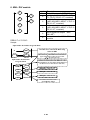
3.6 Terminal Description
3.6.1 Description of main circuit terminals
Terminal symbols TM1 Function Description
L1(L)
Main power input: Single phase: L1(L)/L3(N)
Single/Three phase:L1(L)/L2/L3(N)
L2
Three phase:L1/L2/L3
L3(N)
T1
T2
T3
Inverter output, connect to U/V/W terminals of motor
P
BR
Braking resistor connection terminal: Used in applications when it is required to
stop a high inertia load rapidly. (refer to specifications of the braking resistor)
Ground terminal
Frame1
Single phase: 200V 0.5~1HP
L1(L)
L2
L3(N)
T1
T2
T3
BR
P
Note: the screw on L2 terminal is removed for the single phase input supply models.
Single/Three phase:200V 0.5~1HP; Three phase:200V 2HP; 400V 1~2HP;
L1(L)
L2
L3(N)
T1
P
3-41
T2
BR
T3
Frame2
Single phase:200V 2~3HP;
L1(L)
L2
L3(N)
P
BR
T1
T2
T3
Single/Three phase:200V 2~3HP; Three phase:200V 5HP; 400V 3~5HP;
L1(L)
L2
L3(N)
P
BR
T1
T2
T3
Frame3 & Frame4
Three phase:200V 7.5~20HP; 400V 7.5~25HP
L1
L2
L3
P
BR
3-42
T1
T2
T3
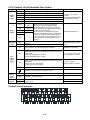
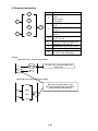
3.6.2 Control circuit terminal description
Type
Digital
input
signal
Terminal
S1
Forward─Stop (Preset), Multi function input terminal
S2
S3
Reverse─Stop (Preset), Multi function input terminal
Preset Speed0(5-02),Multi function input terminal
S4
Preset Speed1(5-03), Multi function input terminal
S5
S6
Preset Speed2(5-05), Multi function input terminal
Fault reset input, Multi function input terminal
R1A
R1B
Relay
output
Terminal function
R1C
R2A
NO(Normally
open)
NC(Normally
closed)
COMMON
R2C
24VPower
supply
The
analog
input
signal
Safety
switch
24 VDC, 8 mA, Optical
coupling
isolation(Max,voltage30 Vdc,
Input impedance 3.3kΩ)
250VAC/1A(30VDC/1A)
COM
Digital signal common terminal (JP1 Switching NPN
position)
Digital signal common terminal (JP1 Switching PNP position)
±15%,Max output current
60mA
10V
Built in Power for an external speed potentiometer
10V(Max current:2mA)
AI1
Multifunctional analog input available JP2 switching voltage or
current input
Voltage:JP2 Switching AV1 position
Current:JP2 Switching AI1 position
0 ~ 10V,(Max current:2mA)
(Input impedance: 153KΩ)
AI2
Multifunctional analog input available JP3 switching voltage or
current input
Voltage:JP3 cut to AV2 position
Current:JP3 cut to AI2 position
0 ~ 10V,0 ~20mA
(Input impedance: 153KΩ)
The analog common terminal
----
Shielding wire connecting terminal (The earth)
----
Multifunctional analog output terminal*3
0 ~10V,(Max current:2mA)
The analog common terminal
----
24V
AGND
The
analog
onput
signal
Multi function output:Run,Fault,setting
Frequency ,Frequency Reached,Auto
Restart,Momentary AC Power Loss,Rapid
Stop ,Base Block Stop Mode,Motor Overload
Protection,Drive Overload
Protection,Over-torque Threshold Level、
Preset Current level Reached、Preset Brake
Frequency Reached,PID Feedback Signal
Loss,Final count value reached, Initial count
value recahed,PLC Status Indicator ,PLC
control…
Signal level
AO
AGND
SF
SG
Terminal SF is for safety switch, SF can cut off the inverter
voltage output.
Control circuit terminal:
3-43
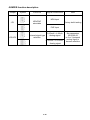
JUMPER function description
Jumper
Symbol
Function
Signal Reference
Note
NPN Input
JP1
NPN/PNP
selectable
Factory defult setting
PNP Input
0~20mA / 4~20mA
JP2/JP3
External signal type
selection
Analog signal
0~10VDC / 2~10VDC
Analog signal
3-44
Set parameters
00-05/00-06
to 2 or 3 (external
analog input) to
become effective
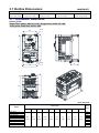
3.7 Outline Dimensions
mm(inch)
Tolerance Table
1 ~ 10 ± 0.1
10 ~ 50 ± 0.2
50 ~ 100 ± 0.3
100 ~ 200 ± 0.5
200 ~ 400 ± 0.8
(0.04~0.40 ± 0.004)
(0.40~1.97 ± 0.01)
(1.97~4 ± 0.01)
(4~7.87 ± 0.02)
(7.87~15.75 ± 0.03)
3.7.1 IP20/NEMA1 dimensions
Frame1 (IP20)
Single/Three phase: 200V 0.5~1HP ; Single phase: 200V 0.5~1HP
Three phase: 200V 2HP; 400V 1~2HP
2- Q1
H
H1
W1
2- Q2
E
D1
D
W2
W
Unit: mm(inch)
Dimensions
Model
W
E510-2P5-H
E510-201-H
E510-2P5-H1F
E510-201-H1F
E510-202-H3
E510-401-H3
E510-402-H3
E510-401-H3F
E510-402-H3F
90.6
(3.57)
W1
81
(3.19)
W2
81
(3.19)
H
163.6
(6.44)
H1
153
(6.02)
3-45
D
149
(5.87)
N.W
(Kg)
D1
141
(5.55)
E
48
(1.89)
Q1
4.3
(0.17)
Q2
4.3
(0.17)
1.6
1.6
1.7
1.7
1.7
1.7
1.7
1.7
1.7
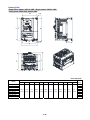
Frame2 (IP20)
Single/Three phase: 200V 2~3HP ; Single phase: 200V 2~3HP
Three phase: 200V 5HP; 400V 3~5HP
2- Q1
H2
H1
H
W1
E
2- Q2
W2
D
D1
D2
W
Unit: mm(inch)
Model
E510-202-H
E510-203-H
E510-202-H1F
E510-203-H1F
E510-205-H3
E510-403-H3
E510-405-H3
E510-403-H3F
E510-405-H3F
Dimensions
W
128.7
(5.07)
W1
118
(4.65)
W2
118
(4.65)
H
187.6
(7.39)
H1
177.6
(6.99)
H2
197.5
(7.78)
3-46
D
149
(5.87)
D1
133.8
(5.27)
D2
141.8
(5.58)
E
48.2
(1.9)
Q1
4.5
(0.18)
Q2
4.5
(0.18)
N.W
(Kg)
2.5
2.5
2.5
2.5
2.5
2.5
2.5
2.5
2.5
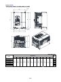
Frame3 (IP20)
Three phase: 200V 7.5~10HP; 400V 7.5~15HP
H1
H2
H
2- Q1
W1
E
2- Q2
W2
D
D1
D2
W
Unit: mm(inch)
Model
E510-208-H3
E510-210-H3
E510-408-H3
E510-410-H3
E510-415-H3
E510-408-H3F
E510-410-H3F
E510-415-H3F
Dimensions
W
186.9
(7.36)
W1
176
(6.92)
W2
175
(6.89)
H
260.9
(10.27)
H1
249.8
(9.83)
H2
273
(10.75)
3-47
D
197
(7.76)
D1
184
(7.24)
D2
189
(7.44)
E
84.7
(3.33)
Q1
4.5
(0.18)
Q2
4.5
(0.18)
N.W
(Kg)
6.5
6.5
6.5
6.5
6.5
6.7
6.7
6.7
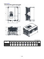
Frame4 (IP20)
Three phase: 200V 15~20HP; 400V 20~25HP
H1
H
H2
2- Q1
W1
E
D1
D2
D
2- Q2
W2
W
Unit: mm(inch)
Model
E510-215-H3
E510-220-H3
E510-420-H3
E510-425-H3
Dimensions
W
W1
W2
H
H1
H2
D
D1
D2
E
Q1
Q2
224.6
(8.84)
207
(8.15)
207
(8.15)
321.6
(12.66)
303.5
(11.95)
330.9
(13.03)
200.5
(7.9)
187.5
(7.38)
192.5
(7.58)
94
(3.7)
4.5
(0.18)
4.5
(0.18)
3-48
N.W
(Kg)
10.1
10.4
10.5
10.5
Frame4 (IP20) (With Filter)
Three phase: 400V 20~25HP
D2
Unit: mm(inch)
Model
E510-420-H3F
E510-425-H3F
Dimensions
W
W1
W2
H
H1
H2
D
D1
D2
E1
E2
Q1
Q2
N.W
(Kg)
224.6
(8.84)
207
(8.15)
207
(8.15)
435.8
(17.16)
303.5
(11.95)
330.9
(13.03)
200.5
(7.9)
187.5
(7.38)
192.5
(7.58)
64.2
(2.53
192.5
(7.58)
6
(0.24)
6
(0.24)
13.7
13.7
3-49
Frame1 (NEMA1)
Single/Three phase: 200V 0.5~1HP; Single: 200V 0.5~1HP
Three phase: 200V 2HP; 400V 1~2HP
2- Q
H
H1
W1
E
E1
D
D1
D2
W
Unit: mm(inch)
Model
E510-2P5-H
E510-201-H
E510-2P5-H1F
E510-201-H1F
E510-202-H3
E510-401-H3
E510-402-H3
E510-401-H3F
E510-402-H3F
Dimensions
W
90.65
(3.57)
W1
80.5
(3.17)
H
186.2
(7.33)
H1
189.2
(7.45)
D
149
(5.87)
3-50
D1
137.8
(5.42)
D2
140.8
(5.54)
E
41.2
(1.62)
E1
120.5
(4.74)
Q
4.33
(0.17)
N.W
(Kg)
1.8
1.8
1.9
1.9
1.9
1.9
1.9
1.9
1.9
Frame2 (NEMA1)
Single/Three phase: 200V 2~3HP; Single: 200V 2~3HP
Three phase: 200V 5HP; 400V 3~5HP
2- Q
H
H1
W1
E
W
D
D1
D2
E1
Unit: mm(inch)
Model
E510-202-H
E510-203-H
E510-202-H1F
E510-203-H1F
E510-205-H3
E510-403-H3
E510-405-H3
E510-403-H3F
E510-405-H3F
Dimensions
W
128.7
(5.06)
W1
118.3
(4.66)
H
210.6
(8.29)
H1
213.6
(8.41)
D
149
(5.87)
3-51
D1
133.8
(5.27)
D2
141.8
(5.58)
E
46.1
(1.81)
E1
121.1
(4.77)
Q
4.5
(0.18)
N.W
(Kg)
2.7
2.7
2.8
2.8
2.8
2.8
2.8
2.8
2.8
Frame3 (NEMA1)
Three phase: 200V 7.5~10HP; 400V 7.5~15HP
2- Q
H1
H
W1
E
E1
D
D1
D2
W
Unit: mm(inch)
Model
E510-208-H3
E510-210-H3
E510-408-H3
E510-410-H3
E510-415-H3
E510-408-H3F
E510-410-H3F
E510-415-H3F
Dimensions
W
186.9
(7.36)
W1
175
(6.89)
H
291
(11.47)
H1
296
(11.65)
D
197
(7.76)
3-52
D1
184
(7.24)
D2
189
(7.44)
E
76.7
(3.02)
E1
170.6
(6.72)
Q
4.5
(0.17)
N.W
(Kg)
6.9
6.9
6.9
6.9
6.9
7.1
7.1
7.1
Frame4 (NEMA1)
Three phase: 200V 15~20HP; 400V 20~25HP
W1
H
H1
2- Q
E
E1
D
D1
D2
W
Unit: mm(inch)
Model
E510-215-H3
E510-220-H3
E510-420-H3
E510-425-H3
Dimensions
W
W1
H
H1
D
D1
D2
E
E1
Q
224.6
(8.84)
207
(8.15)
350.1
(13.78)
355.1
(13.98)
200.5
(7.9)
187.5
(7.38)
192.5
(7.58)
86
(3.89)
174
(6.85)
6
(0.24)
3-53
N.W
(Kg)
10.5
10.5
10.9
11
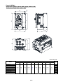
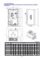
3.7.2 IP66/NEMA 4X dimensions
Frame 1 (IP66/NEMA 4X)
Single/Three phase: 200V 0.5~1HP; Single phase : 200V 0.5~1HP; Three phase : 200V 2HP ;
400V 1~2HP
Unit: mm(inch)
Model
N.W
(Kg)
Dimensions
W
W1
H
H1
H2
D
D1
D2
D3
Q1
Q2
Q3
E510-2P5-HN4R
150.8
133.3
230.2
214.2
248.7
183
200
200
49.5
5.4
5.4
10.6
2.9
E510-2P5-H1FN4S
150.8
133.3
230.2
214.2
248.7
183
200
200
49.5
5.4
5.4
10.6
2.9
E510-201-HN4R
150.8
133.3
230.2
214.2
248.7
183
200
49.5
5.4
5.4
10.6
2.9
E510-201-H1FN4S
150.8
133.3
230.2
214.2
248.7
183
200
49.5
5.4
5.4
10.6
2.9
E510-401-H3N4
150.8
133.3
230.2
214.2
248.7
183
49.5
5.4
5.4
10.6
2.9
E510-401-H3FN4S
150.8
133.3
230.2
214.2
248.7
183
49.5
5.4
5.4
10.6
2.9
E510-402-H3N4
150.8
133.3
230.2
214.2
248.7
183
49.5
5.4
5.4
10.6
2.9
E510-402-H3FN4S
150.8
133.3
230.2
214.2
248.7
183
49.5
5.4
5.4
10.6
2.9
3-54
200
200
200
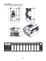
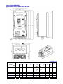
Frame 2 (IP66/NEMA 4X)
Single/Three phase : 200V 2~3HP; Single phase : 200V 2~3HP; Three phase : 200V5HP;
400V 3~5HP ;
Unit: mm(inch)
Model
N.W
(Kg)
Dimensions
W
W1
H
H1
H2
D
E510-202-HN4R
198
115
335
315
337.9
218.4
E510-202-H1FN4S
198
115
335
315
337.9
218.4
E510-203-HN4R
198
115
335
315
337.9
218.4
E510-203-H1FN4S
198
115
335
315
337.9
218.4
E510-205-H3N4
198
115
335
315
337.9
E510-401-H3
198
115
335
315
E510-401-H3FN4S
198
115
335
E510-402-H3
198
115
E510-402-H3FN4S
198
115
D2
D3
Q1
Q2
235.2
79.8
7
7
5.98
235.2
79.8
7
7
5.98
235.2
79.8
7
7
5.98
235.2
79.8
7
7
5.98
218.4
79.8
7
7
5.98
337.9
218.4
79.8
7
7
5.98
315
337.9
218.4
79.8
7
7
5.98
335
315
337.9
218.4
79.8
7
7
5.98
335
315
337.9
218.4
79.8
7
7
5.98
3-55
D1
235.2
235.2
235.2
235.2
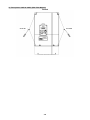
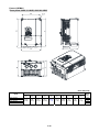
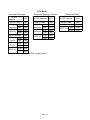
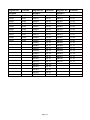
Frame 3 (IP66/NEMA 4X)
Three phase : 200V 8~20HP ; 400V 8~25HP
Unit: mm(inch)
Model
N.W
(Kg)
Dimensions
W
W1
H
H1
H2
D
E510-408-H3N4
222.8
140
460
440
466.3
246.6
E510-408-H3FN4S
222.8
140
460
440
466.3
246.6
E510-410-H3N4
222.8
140
460
440
466.3
246.6
E510-410-H3FN4S
222.8
140
460
440
466.3
246.6
E510-415-H3N4
222.8
140
460
440
466.3
246.6
E510-415-H3FN4S
222.8
140
460
440
466.3
246.6
E510-420-H3N4
222.8
140
460
440
466.3
E510-425-H3N4
222.8
140
460
440
466.3
3-56
D1
D3
Q1
Q2
96
7
7
12.68
96
7
7
12.68
96
7
7
12.68
96
7
7
12.68
96
7
7
12.68
96
7
7
12.68
246.6
96
7
7
12.68
246.6
96
7
7
12.68
266.5
266.5
266.5
D2
263.5
263.5
263.5
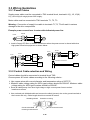
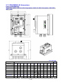
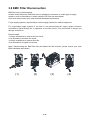
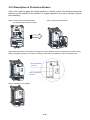
3.8 EMC Filter Disconnection
EMC filter may be disconnected:
Inverter drives with built-in EMC filter are not suitable for connection to certain type of supply
systems, such as listed below; in these cases the RFI filter can be disabled.
In all such cases consult your local electrical standards requirements.
IT type supply systems (ungrounded) & certain supply systems for medical equipment.
For ungrounded supply systems If the filter is not disconnected the supply system becomes
connected to Earth through the Y capacitors on the filter circuit. This could result in danger and
damage to the Drive.
Remove steps :
1 using a screwdriver to remove the front cover.
2 use screwdriver to loosen the screw.
3 using a screwdriver to remove short film.
4 use screwdriver to tighten the screws.
Note:- Disconnecting the EMC filter link will disable the filter function, please consult your local
EMC standards requirement.
(1)
(2)
(3)
3-57
(4)
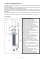
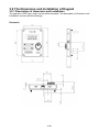
3.9 The Dimension and Installation of Keypad
3.9.1 Description of dimension and installation
The operator is LED type, which can be pulled outwards. The description of dimension and
installation is shown as the followings.
Dimension
3-58
z
Disk installation diagram
The depth of each screw M3 is
greater than the screw holes of 6mm.
The depth of each screw M3 is greater
than the screw holes of 6mm.
Here is the slot to connect the line
of RJ45.
3-59
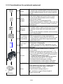
3.9.2 Description of Protective Stickers
If the user needs to apply the digital operator to remote control, the attached protective
stickers can be installed in the position of original operators to prevent unknown objects
from attacking.
Step1: Loosen the four screws between
the operator panel and the inverter.
Step 2: Take out the KEYPAD.
Step3: Mount the patch on the basis of the diagram, whose adhesive surface is towards the position of slots;
apply the ligulate structure in the center to sticking inwards the bare PCB board which sealed the notch.
Here is the bottom
of the slot.
Here is the ligulate
structure.
Step 4: Installation is completed.
3-60
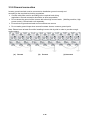
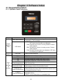
Chapter 4 Software Index
4.1 Keypad Description
4.1.1 Operator Panel Functions
Type
Item
Main digital displays
Digital
display &
LEDs
Variable
Resistor
Keys
On
Keypad
(8
buttons)
LED Status
FREQ SET
RUN
STOP
▲
▼
FWD/REV
(Dual function keys)
DSP/FUN
(Dual function keys)
READ/ENTER
(Dual function keys)
</ RESET
(Dual function keys)
Function
Frequency Display, Parameter, voltage, Current,
Temperature, Fault messages.
Hz/RPM: ON when the frequency or line speed is displayed.
OFF when the parameters are displayed.
FWD: ON while the inverter is running forward. Flashes
while stopped.
REV: ON while the inverter is running reverse. Flashes
while stopped.
FUN: ON when the parameters are displayed. OFF when
the frequency is displayed.
Used to set the frequency
RUN: Run at the set frequency.
STOP: Decelerate or Coast to Stop.
Increment parameter number and preset Values.
Decrement parameter number and preset Values.
FWD: Forward Run
REV: Reverse Run
DSP: Switch between available displays
FUN: Used to examine the parameter content
READ:ENTER:
Used to display the preset Value of parameters and for saving
the changed parameter Values.
“<”Left Shift: used while changing the parameters or
parameter Values
RESET: Use to Reset alarms or resettable faults
4-1
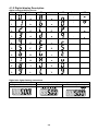
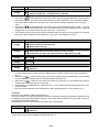
4.1.2 Digital display Description
Alpha numerical display format
LED
Letter
Digit
LED
Letter
LED
Symbol
LED
0
A
n
°
1
b
o
2
C
P
_
3
d
q
.
4
E
r
5
F
S
6
G
t
7
H
u
8
J
V
9
L
Y
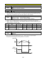
Digital tube lights flashing instructions
Actual output frequency
Set frequency
Digits are lit Continually
Preset digits flashing
Selected digit flashing
4-2
LED display examples
Description
Display
In stop mode shows the set frequency
In run mode shows the actual output frequency
Selected Parameter
Parameter Value
Output Voltage
Output Current in Amps
DC Bus voltage
Temperature
PID feedback Value
Error display
Analogue Current / Voltage AI1 / AI2 . Range ( 0~1000)
LED Status description
LED Indicator light status
Frequency / Line
speed Indicator
Menu mode indicator
Hz/RPM
FUN
ON while displaying frequency or linear speed
ON while not
displaying frequency
or line speed
FWD
ON while running
forward
REV
ON while running
reverse
FWD indicator
REV indicator
4-3
FUN
Flashing while
fire mode
enabled
FWD
Flashing while
stopped in
Forward mode.
REV
Flashing while
stopped in
Reverse mode
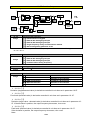
4.1.3 Digital display set up
On power up digital display screens will be as shown below.
DSP/
FUN
DSP/
FUN
2sec later
parameter
frequency
Power supply
User selectable display formats:
12- 00
Display Mode
Range
0
0
0 0
0
High
Low
Each of the above 5 digits can be set to any of the selections below from 0 to 8
【0】:Disable display 【1】:output Current
【2】:output Voltage 【3】:DC voltage
【4】:Temperature
【5】:PID feedback
【6】:AI1
【7】:AI2
【8】:count Value
The highest bit of 12-00 sets the power on the display, other bits set the selected display from range
0-7.as listed above.
Example1: Set parameter 12- 00=【10000】to obtain display format shown below.
DSP/
FUN
2sec later
display:Power supply
Output Current
parameter
DSP/
FUN
DSP/
FUN
Set frequency
4-4
Example 2. Set parameter 12- 00=【12345】 to obtain the display format shown below.
DSP/
FUN
DSP/
FUN
Temperature
<4>
PIDfeedback
<5>
DSP/
FUN
DSP/
FUN
DC voltage
<3>
DSP/
FUN
Output Voltage
<2>
2sec later
Output Current
<1>
Display: Power supply
DSP/
FUN
DSP/
FUN
Parameter
Set Frequency
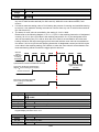
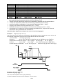
Increment/ Decrement key functions:
1.“▲”/ “▼”:
T1
Short time press
Long time press
T2
Quick pressing of these keys will Increment or Decrement the selected digit by one.
Extended pressing will Increment or Decrement the selected digit continuously.
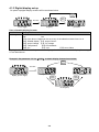
4.1.4 Example of keypad operation
Example1:Modifying Parameters
Frequency
Short time press DSP/FUN once
Short time
press
</RESET once
Short time press
</RESET twice
Short time
Short time
press
once
Short time press
READ/ENTER
once
▲
Short time press
READ/ENTER
once
4-5
press
once
▲
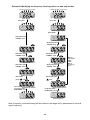
Example2: Modifying the frequency from keypad in run and stop modes.
Modify frequency in stopping
Modify frequency in operating
Power Supply
Power supply
2sec later
2sec later
Set frequency display
Set frequency display
Press RUN
Short time press
</RESET once
Actual frequency
Short time press
</RESET once
Modify bit<unit>
Modify bit<unit>
Short time press
</RESET once
Short time press
</RESET once
Modify bit<ten>
Modify bit<ten>
Short time press
</RESET once
Short time press
</RESET once
Modify bit<hundred>
Modify bit<hundred>
Short time
Short time press
press ▲ once
▲ once
5sec later
Modify bit<hundred+1>
or long time press
READ/ENTER once
Without
pressing the
button
</ENT,
After 5
seconds to
return
Modify bit<hundred+1>
Long time press
READ/ENTER once
Actual frequency
Note: frequency command setting will be limited to the range set by parameters for lower &
upper frequency.
4-6
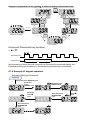
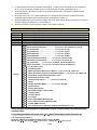
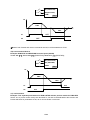
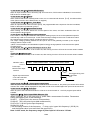
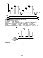
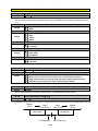
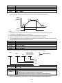
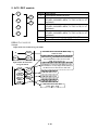
4.1.5 Operation Control
Run
Stop
Power
on
REV FWD
Actual
output
frequency
Run
REV
Run
Stop
FWD
LED
FWD
FWD FWD
FWD
FWD
FWD
FWD
REV
LED
REV
REV REV
REV
REV
REV
REV
4-7
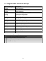
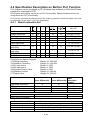
4.2 Programmable Parameter Groups
Parameter Group No.
Description
Group 00
Basic Parameters
Group 01
V/F Pattern Selections and Setup
Group 02
Motor Parameters
Group 03
Multi Function Digital Inputs/Outputs
Group 04
Analog Signal Inputs/Output
Group 05
Preset Frequency Selections
Group 06
Auto Run Function(Auto Sequencer)
Group 07
Start/Stop Command Setup
Group 08
Drive and Motor Protection
Group 09
Communication Function Setup
Group 10
PID Function Setup
Group 11
Performance Control Functions
Group 12
Digital Display & Monitor Functions
Group 13
Inspection & Maintenance Functions
Group 14
PLC Setting Function
Group 15
PLC Monitoring Function
Parameter notes for Parameter Groups
*1
Parameter can be adjusted during running mode
*2
Cannot be modified in communication mode
*3
Does not change with factory reset
*4
*5
*6
Read only
Available for above V1.1
Available for above V1.3
4-8
G ro up 00- Basic parameters
No.
Description
00-00
Control Mode Selection
00-01
Reserved
00-02
Main Run Command
Source Selection
00-03
Alternative Run Command
Source Selection
00-04
Operation Modes for
External Terminals
00-05
Main Frequency Command
Source Selection
00-06
00-07
Alternative Frequency
Command Source Selection
Main and Alternative
Frequency Command Modes
00-10
Communication
Frequency Command
Frequency Command
Save on Power Down
Initial Frequency
Selection (keypad mode)
00-11
00-12
00-13
00-14
00-15
00-16
00-17
00-18
00-19
00-20
Initial Frequency Setpoint
Frequency Upper Limit
Frequency Lower Limit
Acceleration Time 1
Deceleration Time 1
Acceleration Time 2
Deceleration Time 2
Jog Frequency
Jog Acceleration Time
Jog Deceleration Time
00-08
00-09
Factory
Setting
Range
0:V/F Mode
1:Vector Mode
0:Keypad
1:External Run/Stop Control
2:Communication
3:PLC
0:Keypad
1:External Run/Stop Control
2:Communication
0:Forward/Stop-Reverse/Stop
1:Run/Stop- Reverse/Forward
2: 3 Wire Control Mode-Run/Stop
0:UP/DOWM of Keypad
1:Potentiometer on Keypad
2:External AI1 Analog Signal Input
3:External AI2 Analog Signal Input
4:External Up/Down Frequency Control
5:Communication Setting Frequency
6:PID Ouput Frequency
7:Pulse Input
0:UP/DOWM of Keypad
1:Potentiometer on Keypad
2:External AI1 Analog Signal Input
3:External AI2 Analog Signal Input
4:External Up/Down Frequency Control
5:Communication Setting Frequency
6:PID Ouput Frequency
7:Pulse Input
0:Main or Alternative Frequency
1:Main Frequency+ Alternative
Frequency
0.00~650.00
0: Disable
1: Enable
0:by Current Frequency Command
1:by 0 Frequency Command
2:by 00-11
0.00~650.00
0.01~650.00
0.00~649.99
0.1~3600.0
0.1~3600.0
0.1~3600.0
0.1~3600.0
1.00~25.00
0.1~25.5
0.1~25.5
4-9
Unit
0
-
0
-
0
-
0
-
0
-
Note
*6
4
-
*6
0
60.00
Hz
0
-
0
-
50.00/60.00
50.00/60.00
0.00
10.0
10.0
10.0
10.0
2.00
0.5
0.5
Hz
Hz
Hz
Sec
Sec
Sec
Sec
Hz
Sec
Sec
*4
*1
*1
*1
*1
*1
*1
*1
G ro up 01- V/F Pattern selection & Setup
No.
Description
01-00
Volts/Hz Patterns
01-01
V/F Max voltage
01-02
01-03
01-04
01-05
01-06
01-07
01-08
01-09
Max Frequency
Max Frequency Voltage Ratio
Mid Frequency 2
Mid Frequency Voltage Ratio 2
Mid Frequency 1
Mid Frequency Voltage Ratio 1
Min Frequency
Min Frequency Voltage Ratio
Volts/Hz Curve Modification
(Torque Boost)
V/F start Frequency
Slip compensation gain
V/F Mode Select
01-10
01-11
01-12
01-13
Factory
Setting
Range
Unit
0~18
200V:170.0~264.0
400V:323.0~528.0
0.20 ~ 650.00
0.0 ~ 100.0
0.10 ~ 650.00
0.0 ~ 100.0
0.10 ~ 650.00
0.0 ~ 100.0
0.10 ~ 650.00
0.0 ~ 100.0
0/9
220.0/440.0
Vac
50.00/60.00
100.0
25.00/30.00
50.0
10.00/12.00
20.0
0.50/0.60
1.0
Hz
%
Hz
%
Hz
%
Hz
%
0 ~ 10.0
0.0
%
0.00~10.00
0.05~10.00
0.00
0.10
Hz
S
0 : Mode 0 1 : Mode 1
0
Note
-
*1
-
G ro up 02- Motor parameters
No.
02-00
02-01
Description
02-03
Motor No Load Current
Motor Rated Current (OL1)
Motor rated Slip
Compensation
Motor rated speed
02-04
Motor rated voltage
02-05
02-06
02-07
02-08
~
02-13
Motor rated power
Motor rated frequency
Motor pole number
02-14
Auto Tune
02-15
02-16
Stator resistance gain
Rotor resistance gain
02-02
Factory
Setting
Range
0~[(Patameter 02-01)-0.1]
0.2~100
-
0.0 ~ 200.0
0.0
0~39000
200V: 170.0~264.0
400V: 323.0~528.0
0.1~37.0
0~650.0
2 ~16
220.0/440.0
50.0/60.0
4
Unit
Note
Amps(AC)
A
*4
*4
%
*1
Rpm
*4
V
KW
Hz
-
Reserved
0: Disable
1: Start Auto tune function.
-------
4-10
0
*3*4
*3*4
No.
03-00
03-01
03-02
03-03
03-04
Group 03- External Digital Inputs and Relay Output Functions
Factory
Description
Range
Setting
0
Multifunction Input Term. S1
0:Forward/Stop Command
1:Reverse/Stop Command
1
Multifunction Input Term. S2
2:Preset
Speed
0(5-02)
2
Multifunction Input Term. S3
3:Preset Speed 1(5-03)
3
Multifunction Input Term. S4
4:Preset Speed 2(5-05)
4
Multifunction Input Term. S5
5:Preset Speed 3(5-09)
Unit
Note
-
6:Jog Forward Command
7:Jog Reverse Command
8:Up Command
9:Down Command
10:Acc/Dec 2
11:Acc/Dec Disabled
12:Main/Alternative run source
select
13:Main/ Alternative Frequency
Command select
14:Rapid Stop ( Decel to stop )
03-05
Multifunction Input Term. S6
03-06
Up/Down frequency step
03-07
Up/Down Keep Frequency Status
after Stop Command
03-08
S1~S6 scan confirmation
03-09
15:Base Block
16:Disabl PID Function
17: Fault Reset
18:Auto Run Mode Enable
19:Speed Search
20:Energy Saving (only V/F)
21:Reset PID integral value to Zero
22:Counter Input
23:Counter Reset
24:PLC Input
25:Pulse Input-Width Measure (S3)
26:Pulse Input-Frequenct Measure
(S3)
27:Enable KEB Function
28:Fire mode function (Valid for
software issued after rev. 1.1)
0.00~5.00
0:When Up/Down is used, the preset
frequency is held as the inverter
stops, and the UP/Down function is
disabled
1:When Up/Down is used, the preset
frequency is reset to 0 Hz as the
inverter stops.
2:When Up/Down is used, the preset
frequency is held as the inverter
stops, and the UP/Down is available.
17
*6
*6
0.00
Hz
0
-
1~200 Number of Scan cycles
10
2ms
S1~ S5 switch type select
xxxx0:S1 NO
xxx0x:S2 NO
xx0xx:S3 NO
x0xxx:S4 NO
0xxxx:S5 NO
xxxx1:S1 NC
xxx1x:S2 NC
xx1xx:S3 NC
x1xxx:S4 NC
1xxxx:S5 NC
00000
-
03-10
S6 switch type select
xxxx0:S6 NO xxxx1:S6 NC
00000
-
03-11
Output Relay RY1
( Terminals R1A,R1B, R1C )
0:Run
0
-
4-11
No.
03-12
03-13
03-14
03-15
03-16
03-17
03-18
03-19
Group 03- External Digital Inputs and Relay Output Functions
Factory
Description
Range
Setting
1:Fault
2:Setting Frequency Reached
3:Frequency Reached. Set by
(3-13±3-14)
4:Output Frequency Detection1(>
3-13)
5:Output Frequency Detection2(<
3-13)
6:Auto Restart
7:Momentary AC Power Loss
8:Rapid Stop
9:Base Block
10:Motor Overload Protection(OL1)
11:Drive Overload Protection(OL2)
Output Relay RY2.
1
12:Over-torque Threshold Level
( Terminals R2A, R2C )
(OL3)
13:Preset Output Current Reached
(03-15~16)
14:Brake Control ON (03-17~18)
15:PID Feedback Signal Loss
16:Final count value reached
(3-22~23)
17:Initial count value reached
(3-22~23)
18:PLC Status Indicator (00-02)
19:PLC control
20:Zero Speed
0.00~650.00
0.00
Frequency Reached Level
Frequency Reached Detection
Range (±)
Preset output current reached
Preset output Current detection
delay Time
Brake Release
level
Brake Engage
Level
Relay Output function type
03-22
03-23
Internal / external multi-function
input terminal selection
Action to set the internal
multi-function input terminals
Final preset Count reached
Initial preset count reached
03-24
Low Current detection selection.
03-20
03-21
Note
Hz
*6
*1
*1
0.00~30.00
2.00
Hz
0.1~15.0
0.1
A
0.1~10.0
0.1
Sec
0.00~20.00
0.00
Hz
0.00~20.00
0.00
Hz
0:A (Normally open)
1:B (Normally close)
0
-
0~63
0
-
0~63
0
-
0~9999
0~9999
0:Disable
1:Enable
5%~100%
0
0
-
0
-
20%
%
20.0
Sec
0.1
1.00
kHz
Low Current Detection Level
Low Current Detection Delay
03-26
0.0~50.0s
Time
0.01~1.00
03-27 Pulse Frequency
0.01~9.99
03-28 Pulse Frequency Gain
※ “NO” indicates normally open, “NC” indicates normally closed.
03-25
Unit
4-12
*6
*6
Group 04- Analog signal inputs / Analog output
No.
Description
AI1
04-00
04-01
04-02
04-03
04-04
04-05
04-06
04-07
04-08
04-09
04-10
Analog Input Signal Type
Select (AI1/AI2)
AI1 Signal Verification Scan Rate
AI1 Gain
AI1 Bias
AI1 Bias Selection
AI1 Slope
AI2 Signal Verification Scan
Rate
AI2 Gain
AI2 Bias
AI2 Bias Selection
AI2 Slope
Factory
Setting
Range
Note
AI2
(0): 0~10V (0~20mA)
0~10V (0~20mA)
(1): 0~10V (0~20mA)
2~10V (4~20mA)
(2): 2~10V (4~20mA)
0~10V (0~20mA)
(3): 2~10V (4~20mA)
2~10V (4~20mA)
1~200
0 ~ 1000
0 ~ 100
0: Positive
0: Positive
Unit
0
-
50
100
0
0
0
2ms
%
%
-
1~200
50
2ms
0 ~ 1000
0 ~ 100
0: Positive
0: Positive
100
0
0
0
%
%
-
*1
*1
*1
*1
0
-
*1
100
0
%
%
*1
*1
1: Negative
1: Negative
1: Negative
1: Negative
*1
*1
*1
*1
04-11
Analog Output (AO) Mode
0: Output Frequency
1: Frequency Command
2: Output Voltage
3: DC Bus Voltage
4: Motor Current (100% rated current)
04-12
04-13
Analog Output (AO) Gain
Analog Output (AO) Bias
0 ~ 1000
0 ~ 100
04-14
AO Bias Selection
0: Positive
1: Negative
0
-
*1
04-15
AO Slope
0: Positive
1: Negative
0
-
*1
04-16
F-Gain Function
0: Invalid
1: Effective
0
-
*1
4-13
Group 05- Preset Frequency Selections
No.
05-00
05-01
05-02
05-03
05-04
05-05
05-06
05-07
05-08
05-09
05-10
05-11
05-12
05-13
05-14
05-15
05-16
05-17
05-18
05-19
05-20
05-21
05-22
05-23
05-24
05-25
05-26
05-27
05-28
05-29
05-30
05-31
05-32
05-33
05-34
05-35
05-36
05-37
05-38
05-39
Description
Preset Speed Control
Mode Selection
Preset Speed 0
(Keypad Freq)
Preset Speed1 (Hz)
Preset Speed2 (Hz)
Preset Speed3 (Hz)
Preset Speed4 (Hz)
Preset Speed5 (Hz)
Preset Speed6 (Hz)
Preset Speed7 (Hz)
Preset Speed8 (Hz)
Preset Speed9 (Hz)
Preset Speed10 (Hz)
Preset Speed11 (Hz)
Preset Speed12 (Hz)
Preset Speed13 (Hz)
Preset Speed14 (Hz)
Preset Speed15 (Hz)
Preset Speed0-Acctime
Preset Speed0-Dectime
Preset Speed1-Acctime
Preset Speed1-Dectime
Preset Speed2-Acctime
Preset Speed2-Dectime
Preset Speed3-Acctime
Preset Speed3-Dectime
Preset Speed4-Acctime
Preset Speed4-Dectime
Preset Speed5-Acctime
Preset Speed5-Dectime
Preset Speed6-Acctime
Preset Speed6-Dectime
Preset Speed7-Acctime
Preset Speed7-Dectime
Preset Speed8-Acctime
Preset Speed8-Dectime
Preset Speed9-Acctime
Preset Speed9-Dectime
Preset
Speed10-Acctime
Preset
Speed10-Dectime
Preset
Speed11-Acctime
Range
0: Common Accel/Decel
Accel/Decel 1 or 2 apply to all speeds
1: Individual Accel/Decel for each preset speed
0-15 apply to the selected preset speeds
(Acc0/Dec0~Acc15/Dec15)
0.00 ~ 650.00
0.1 ~ 3600.0
4-14
Factory
Setting
0
Unit
Note
-
5.00
Hz
5.00
10.00
20.00
30.00
40.00
50.00
50.00
0.00
0.00
0.00
0.00
0.00
0.00
0.00
0.00
10.0
10.0
10.0
10.0
10.0
10.0
10.0
10.0
10.0
10.0
10.0
10.0
10.0
10.0
10.0
10.0
10.0
10.0
10.0
10.0
Hz
Hz
Hz
Hz
Hz
Hz
Hz
Hz
Hz
Hz
Hz
Hz
Hz
Hz
Hz
Sec
Sec
Sec
Sec
Sec
Sec
Sec
Sec
Sec
Sec
Sec
Sec
Sec
Sec
Sec
Sec
Sec
Sec
Sec
Sec
*1
*1
*1
*1
*1
*1
*1
*1
*1
*1
*1
*1
*1
*1
*1
*1
*1
*1
*1
*1
*1
*1
*1
*1
*1
*1
*1
*1
*1
*1
*1
*1
*1
*1
*1
10.0
Sec
*1
10.0
Sec
*1
10.0
Sec
*1
Group 05- Preset Frequency Selections
No.
05-40
05-41
05-42
05-43
05-44
05-45
05-46
05-47
05-48
Description
Range
Preset
Speed11-Dectime
Preset
Speed12-Acctime
Preset
Speed12-Dectime
Preset
Speed13-Acctime
Preset
Speed13-Dectime
Preset
Speed14-Acctime
Preset
Speed14-Dectime
Preset
Speed15-Acctime
Preset
Speed15-Dectime
Factory
Setting
Unit
Note
10.0
Sec
*1
10.0
Sec
*1
10.0
Sec
*1
10.0
Sec
*1
10.0
Sec
*1
10.0
Sec
*1
10.0
Sec
*1
10.0
Sec
*1
10.0
Sec
*1
Factory
Setting
Unit
Note
Group 06- Auto Run Function (Auto Sequencer)
No.
06-00
06-01
06-02
06-03
06-04
06-05
Description
Auto Run Mode
Selection
(Sequencer)
Auto _ Run Mode
Frequency Command 1
Auto _ Run Mode
Frequency Command 2
Auto _ Run Mode
Frequency Command 3
Auto _ Run Mode
Frequency Command 4
Auto _ Run Mode
Frequency Command 5
Range
0: Disabled.
1: Single cycle.
(Continues to run from the Unfinished step if
restarted).
2: Periodic cycle.
(Continues to run from the unfinished step if
restarted).
3: Single cycle, then holds the speed Of final
step to run. (Continues to run from the
unfinished step if restarted).
4: Single cycle.
(Starts a new cycle if restarted).
5: Periodic cycle.
(Starts a new cycle if restarted).
6: Single cycle, then hold the speed of final step
to run. (Starts a new cycle if restarted).
0.00~650.00
4-15
0
-
0.00
Hz
*1
0.00
Hz
*1
0.00
Hz
*1
0.00
Hz
*1
0.00
Hz
*1
Group 06- Auto Run Function (Auto Sequencer)
No.
06-06
06-07
06-08
06-09
06-10
06-11
06-12
06-13
06-14
06-15
06-16
06-17
06-18
06-19
06-20
06-21
06-22
06-23
06-24
06-25
06-26
Description
Auto _ Run Mode
Frequency Command 6
Auto _ Run Mode
Frequency Command 7
Auto _ Run Mode
Frequency Command 8
Auto _ Run Mode
Frequency Command 9
Auto _ Run Mode
Frequency
Command10
Auto _ Run Mode
Frequency Command
11
Auto _ Run Mode
Frequency Command
12
Auto _ Run Mode
Frequency Command
13
Auto _ Run Mode
Frequency Command
14
Auto _ Run Mode
Frequency Command
15
Auto_ Run Mode
Running Time Setting 0
Auto_ Run Mode
Running Time Setting 1
Auto_ Run Mode
Running Time Setting 2
Auto_ Run Mode
Running Time Setting 3
Auto_ Run Mode
Running Time Setting 4
Auto_ Run Mode
Running Time Setting 5
Auto_ Run Mode
Running Time Setting 6
Auto_ Run Mode
Running Time Setting 7
Auto_ Run Mode
Running Time Setting 8
Auto_ Run Mode
Running Time Setting 9
Auto_ Run Mode
Running Time Setting
10
Range
0.0 ~ 3600.0
4-16
Factory
Setting
Unit
Note
0.00
Hz
*1
0.00
Hz
*1
0.00
Hz
*1
0.00
Hz
*1
0.00
Hz
*1
0.00
Hz
*1
0.00
Hz
*1
0.00
Hz
*1
0.00
Hz
*1
0.00
Hz
*1
0.0
Sec
0.0
Sec
0.0
Sec
0.0
Sec
0.0
Sec
0.0
Sec
0.0
Sec
0.0
Sec
0.0
Sec
0.0
Sec
0.0
Sec
Group 06- Auto Run Function (Auto Sequencer)
No.
06-27
06-28
06-29
06-30
06-31
06-32
06-33
06-34
06-35
06-36
06-37
06-38
06-39
06-40
06-41
06-42
06-43
06-44
06-45
06-46
06-47
Description
Auto_ Run Mode
Running Time Setting
11
Auto_ Run Mode
Running Time Setting
12
Auto_ Run Mode
Running Time Setting
13
Auto_ Run Mode
Running Time Setting
14
Auto_ Run Mode
Running Time Setting
15
Auto_ Run Mode
Running Direction 0
Auto_ Run Mode
Running Direction 1
Auto_ Run Mode
Running Direction 2
Auto_ Run Mode
Running Direction 3
Auto_ Run Mode
Running Direction 4
Auto_ Run Mode
Running Direction 5
Auto_ Run Mode
Running Direction 6
Auto_ Run Mode
Running Direction 7
Auto_ Run Mode
Running Direction 8
Auto_ Run Mode
Running Direction 9
Auto_ Run Mode
Running Direction10
Auto_ Run Mode
Running Direction 11
Auto_ Run Mode
Running Direction12
Auto_ Run Mode
Running Direction13
Auto_ Run Mode
Running Direction 14
Auto_ Run Mode
Running Direction 15
Range
0: Stop
1: Forward
2: Reverse
※ Frequency of the step 0 is set by parameter 05-01, keypad frequency.
4-17
Factory
Setting
Unit
0.0
Sec
0.0
Sec
0.0
Sec
0.0
Sec
0.0
Sec
0
-
0
-
0
-
0
-
0
-
0
-
0
-
0
-
0
-
0
-
0
-
0
-
0
-
0
-
0
-
0
-
Note
Group 07- Start/Stop Command Setup
No.
07-00
07-01
07-02
07-03
07-04
07-05
07-06
07-07
07-08
Description
Momentary Power Loss
and Restart
Auto Restart Delay
Time
Number of Auto Restart
Attempts
Reset Mode Setting
Direct Running on
Power Up
Delay-ON Timer
DC Injection Brake Start
Frequency (Hz) In Stop
Mode
DC Injection Brake
Level (%) In Stop Mode
DC Injection Brake
Time (Seconds)
In Stop Mode
07-09
Stopping Method
07-10
Starting Methods
Starting method for auto
restart after fault
Power Loss Ride
Through Time
Main Circuit Low
Voltage Detection Level
Kinetic Energy Back-up
Deceleration Time
DC Break Select
DC Break Level
(Voltage)
07-11
07-12
07-13
07-14
07-15
07-16
Range
Factory
Setting
Unit
0: Momentary Power Loss and Restart Disable
1: Momentary Power Loss and Restart Enable
0
0.0~800.0
0.0
0~10
0
-
0
-
1
-
Sec
0: Enable Reset Only when Run Command is Off
1: Enable Reset when Run Command is On or
Off
0: Enable Direct run on power up
1: Disable Direct run on power up
1.0~300.0
1.0
Sec
0.10 ~ 10.00
1.5
Hz
0.0 ~ 150.0
50.0
%
0.0 ~ 25.5
0.5
Sec
0: Deceleration to stop
1: Coast to stop
0: Normal Start 1: Speed Search
0
-
0
-
0: Speed Search
0
-
1: Normal start
Note
0.0 ~ 2.0
0.5
Sec
150.0~210.0 300.0~420.0
190.0/3
80.0
Vac
0.0~25.0: KEB Deceleration Time
0.0
Sec
0 : Current Mode 1 : Voltage Mode
1
-
*6
0.0~10.0
4.0
-
*6
4-18
Group 08- Drive & Motor Protection Functions
No.
08-00
08-01
08-02
08-03
08-04
08-05
Description
Trip Prevention
Selection
Trip Prevention Level
During Acceleration (%)
Trip Prevention Level
During Deceleration (%)
Trip Prevention Level in
Run Mode (%)
Over Voltage
Prevention
Level in Run Mode
Electronic Motor
Overload Protection
Operation Mode
08-06
Operation After
Overload Protection is
Activated
08-07
Over Heat Protection
( cooling fan control)
08-08
AVR Function
(Auto Voltage
Regulation)
08-09
08-10
Input Phase Loss
Protection
Output Phase Losts
Protection
08-11
Motor Type Selection
08-12
Motor Overload
Protection Curve
1
Range
Factory
Setting
Unit
xxxx0: Enable Trip Prevention During
Acceleration
xxxx1: Disable Trip Prevention During
Acceleration
xxx0x: Enable Trip Prevention During
Deceleration
xxx1x: Disable Trip Prevention During
Deceleration
xx0xx: Enable Trip Prevention in Run
Mode
xx1xx: Disable Trip Prevention in Run
Mode
x0xxx: Enable Over Voltage Prevention
in Run Mode
x1xxx: Disable Over Voltage Prevention
in Run Mode
01000
50 ~ 200
200
50 ~ 200
200
50 ~ 200
200
350.0~390.0/700.0~780.0
380.0/7
60.0
0: Enable Electronic Motor Overload Protection
1: Disable Electronic Motor Overload Protection
0
-
0
-
1
-
4
-
0
-
0
-
0
-
0
-
0: Coast-to-Stop After Overload Protection is
Activated
1: Drive Will Not Trip when Overload Protection
is Activated (OL1)
0: Auto (Depends on temp.)
1: Operate while in RUN Mode
2: Always Run
3: Disabled
0: AVR Function Enable
1: AVR Function Disable
2: AVR Function Disable for Stop
3: AVR Function Disable for Deceleration.
4: AVR Function Disabled for Stop and
Deceleration.
5: When VDC>360V, AVR Function is Disabled
for Stop and Deceleration.
0: Disabled
1: Enabled
0: Disabled
1: Enabled
0: Overload protection (Standard Motor)
1: Overload protection (Inverter Duty Motor)
0: Motor Overload Protection for General loads
(OL=103 %) (150% for 1 Minutes)
1: Motor Over load Protection for HVAC ( Fan &
Pump) (OL=113%) (123% for 1 Minutes).
Base on the percentage of inverter rated current.
4-19
-
Note
*5
%1
VD
C
*5
Group 08- Drive & Motor Protection Functions
No.
Description
08-13
Over Torque Detection
Control
08-14
Over torque protection
action
08-15
08-16
0: Over Torque Detection Disabled
1: Detected After the Setting Frequency
2: Detected When Running
0: Stop Output After Over Torque Detection
(Free Run to Stop)
1: Continue Running After Over Torque
Detection (Display only OL3)
Over Torque Detection
Level
Over Torque Detection
Time
08-17
Fire Mode
08-18
Ground Fault Detection
Factory
Setting
Range
Unit
0
-
0
-
30~300
160
-
0.0~25.0
0.1
-
0
-
0:Disabled.
1: Enabled
0: Disabled
1: Enabled
Note
*5
1
Notes:Regarding fire mode function, please refer to the conditions below,
1. Before the software rev. 1.1, the fire mode is funtional when 08-17 = 1
2. After the software 1.1,the firemode is functional when 03-00~03-05 =【28】
3. The keypad display will indicate FIrE
4. Under fire mode function, the inverter will run at full speed
Group 09- Communication function setup
No.
Description
09-00
Assigned Communication
Station Number
09-01
RTU/ASCII Code Selection
09-02
Baud Rate Setting (bps)
09-03
Stop Bit Selection
09-04
Parity Selection
09-05
Data Format Selection
09-06
Communication Time-Out
Detection Time
09-07
Communication Time Out
Operation Selection
09-08
09-09
Error 6 Verification Time.
Drive Transmit Delay Time(ms)
Range
1 ~ 32
0:RTU Code
1:ASCII Code
0:4800
1:9600
2:19200
3:38400
0:1 Stop Bit
1:2 Stop Bits
0:Without Parity
1:With Even Parity
2:With Odd Parity
0: 8-Bits Data
1: 7-Bits Data
0.0 ~ 25.5
0:Deceleration to Stop
(00-15: Deceleration Time 1)
1:Coast to Stop
2:Deceleration to Stop
(00-17: Deceleration Time 2)
3:Continue Operating
1 ~ 20
5 ~ 65
4-20
Factory
Setting
Unit
Note
1
-
*2*3
0
-
*2*3
2
bps
*2*3
0
-
*2*3
0
-
*2*3
0
-
*2*3
0.0
Sec
0
-
3
5
ms
Group 10- PID Function Setup
No.
Description
Range
Factory
Setting
Unit
Note
PID Target Value Selection
(When 00-03\00-04=6 This
Function is Enabled)
0: Potentiometer on Keypad
1: Analog Signal Input. (AI1)
2: Analog Signal Input. (AI2)
3: Frequency Set by Communication
4: Keypad Frequency Parameter
10-02
1
-
*1
10-01
PID Feedback Value Selection
0: Potentiometer on Keypad
1: Analog Signal Input. (AI1)
2: Analog Signal Input. (AI2)
3: Frequency Set by Communication
2
-
*1
10-02
PID Target(Keypad Input)
50.0
%
*1
10-03
PID Mode Selection
0
-
10-04
10-05
10-06
10-07
Feedback Gain Coefficient
Proportional Gain
Integral Time
Derivative Time
10-08
PID Offset
10-09
10-10
PID Offset Adjust
PID Output Lag Filter Time
10-00
10-11
10-12
10-13
10-14
10-15
10-16
10-17
10-18
10-19
10-20
10-21
10-22
Feedback Loss Detection
Mode
Feedback Loss Detection
Level
Feedback Loss Detection
Delay Time
Integration Limit Value
Integral Value Resets to Zero
when Feedback Signal Equals
the Target Value
Allowable Integral value Error
Margin (Units, 1 Unit = 1/8192)
PID Sleep Frequency Level
PID Sleep Function Delay Time
PID Wake up frequency Level
PID Wake up function Delay Time
Max PID Feedback Setting Level
Min PID Feedback Setting Level
0.0~100.0
0: Disabled
1: Deviation D Control.
FWD Characteristic.
2: Feedback D Control
FWD Characteristic.
3: Deviation D Control
Reverse Characteristic.
4: Feedback D Control
Reverse Characteristic.
0.00 ~ 10.00
0.0 ~ 10.0
0.0 ~ 100.0
0.00 ~ 10.00
0: Positive
1: Negative
0 ~ 109
0.0 ~ 2.5
1.00
1.0
10.0
0.00
0
0
0.0
Sec
Sec
*1
*1
*1
*1
-
*1
%
Sec
*1
*1
0: Disabled
1: Enabled - Drive Continues to
Operate After Feedback Loss
2: Enabled - Drive "STOPS"
After Feedback Loss
0
-
0 ~ 100
0
%
0.0 ~25.5
1.0
Sec
0 ~ 109
100
%
0: Disabled
1: After 1 Second
30: After 30 Second (0~30)
0
-
0 ~ 100
0
-
0.00~650.00
0.0 ~25.5
0.00 ~ 650.00
0.0 ~ 25.5
0 ~999
0 ~999
0.00
0.0
0.00
0.0
100
0
4-21
Hz
Sec
Hz
Sec
-
*1
*1
*1
Group 11- Performance Control Functions
No.
Description
11-00
Reverse Operation Control
11-01
Carrier Frequency (kHz)
11-02
Carrier Mode Selection
11-03
11-04
11-05
11-06
11-07
11-08
11-09
11-10
11-11
11-12
11-13
11-14
11-15
11-16
11-17
Carrier Frequency
Reduction by Temperature
Rise
S-Curve Acc 1
S-Curve Acc 2
S-Curve Dec 3
S-Curve Dec 4
Skip Frequency 1
Skip Frequency 2
Skip Frequency 3
Skip Frequency Range
Bandwith (±)
Energy Saving Gain (V/F
Mode)
Regeneration Avoidance
Operation Selection
Regeneration Avoidance
Operation level
Regeneration Avoidance
Frequency Limit Compensation
Regeneration Avoidance
Voltage Gain
Regeneration Avoidance
Frequency Gain
Range
0: Reverse Command is Enabled
1: Reverse Command is Disabled
1~16
0: Mode0, 3Phase PWM modulation
1: Mode1, 2Phase PWM modulation
2: Mode2, 2Phase Random PWM
Modulation
Factory
Setting
unit
Note
0
-
5
KHz
0
-
0:Disabled
1:Enabled
0
-
0.0 ~ 4.0
0.0 ~ 4.0
0.0 ~ 4.0
0.0 ~ 4.0
0.00 ~ 650.00
0.00 ~ 650.00
0.00 ~ 650.00
0.2
0.2
0.2
0.2
0.00
0.00
0.00
Sec
Sec
Sec
Sec
Hz
Hz
Hz
*1
*1
*1
0.00 ~ 30.00
0.00
Hz
*1
0 ~ 100
80
%
0:Invalid
1:Vaild
2:Vaild (Only in The Constant Speed)
200V:300.0~400.0
400V:600.0~800.0
0
380.0
760.0
V
0.00 ~ 15.00
3.00
Hz
0~200
100
%
0~200
100
%
4-22
Group 12 Digital Display & Monitor Functions
No.
12-00
Description
Extended Display Mode
Factory
Setting
Range
00000~88888
Each digit can be set from 0 to 8 as
listed below.
0: Default Display
(Frequency and Parameters)
1:Output Current
2:Output Voltage
3:DC Voltage
4:Temperature
5:PID Feedback
6:Analog Signal Input. (AI1)
7:Analog Signal Input. (AI2)
8:Input Count value
0:Integer (xxx)
1:One Decimal Place (xx.x)
2:Two Decimal Places (x.xx)
0:xxx-1:xxxpb(pressure)
2:xxxfl(flow)
Unit
Note
00000
-
*1
0
-
*1
0
-
*1
RPM
*1
12-01
PID Feedback Display Format
12-02
PID Feedback Display Unit
Setting
12-03
Custom Units (Line Speed)
Value
0~65535
1500/1800
Custom Units (Line Speed)
Display Mode
0:Drive Output Frequency is Displayed
1:Line Speed.Integer.(xxxxx)
2:Line Speed.One Decimal Place.
(xxxx.x)
3:Line Speed.Two Decimal Places
(xxx.xx)
4:Line Speed.Three Decimal Places
(xx.xxx)
0
-
*1
-
-
*4
00000
-
*1
12-04
S1
12-05
S4 S5
S6
Inputs and Output
Logic Status Display
( S1~S6, RY1 and RY2)
RY1
12-06
S2 S3
Alarm Selections for Inverter
Components Life Expectancy
RY2
PLC
xxxx0:Life Alarm of Inrush Current
Suppression Circuit is Invalid
xxxx1:Life Alarm of Inrush Current
Suppression Circuit is Valid
xxx0x:Life Alarm of Control Circuit
Capacitors is Invalid
xxx1x:Life Alarm of Control Circuit
Capacitors is Valid
xx0xx:Life Alarm of Main Circuit
Capacitors is Invalid
xx1xx:Life Alarm of Main Circuit
Capacitors is Valid
4-23
Group 12 Digital Display & Monitor Functions
No.
12-07
12-08
12-09
12-10
12-11
12-12
12-13
12-14
12-15
Description
Factory
Setting
Range
Detect Main Circuit
Capacitors
Display of Inrush Current
Suppression Circuit
Display of Control Circuit
Capacitors
Reserved
Output Current when
Fault Appeared
Output Voltage when
Fault Appeared
Output Frequency when
Fault Appeared
DC Bus Voltage when
Fault Appeared
Frequency Command when
Fault Appeared
Unit
Note
Reserved
0~100
100
%
0~100
100
%
----
0
A
----
0
Vac
----
0
Hz
----
0
Vac
----
0
Hz
Group 13 Inspection & Maintenance Functions
No.
Description
13-00
13-01
Drive Horsepower Code
Software Version
Fault Log (Latest 3
Faults)
Accumulated Inverter
Operation Time 1
Accumulated Inverter
Operation Time 2
Accumulated Inverter
Operation Time Mode
13-02
13-03
13-04
13-05
13-06
Parameter Lock
13-07
Parameter Lock Code
13-08
Reset Drive to Factory
Settings
-------
Factory
Setting
-
----
-
-
*3*4
0~23
-
hour
*3
0~65535
----
day
*3
0
-
*3
0
-
00000
-
00000
-
Range
0: Power On time
1: Operation time
0:Enable all Functions
1:Preset Speeds from 05-01 to 05-15 Can’t be
Changed
2:All Functions Can’t be Changed Except
for Preset speeds from 05-01 to 05-15
3:Disable All Functions Except 13-06
00000~65535
1150:Reset to Factory Setting(50Hz System)
1160:Reset to Factory Setting(60 Hz System)
1112:Reset PLC
4-24
unit
Note
-
*3
*3*4
Group 14 PLC Setting function
No.
14-00
14-01
14-02
14-03
14-04
14-05
14-06
14-07
14-08
14-09
14-10
14-11
14-12
14-13
14-14
14-15
14-16
14-17
14-18
14-19
14-20
14-21
14-22
14-23
14-24
14-25
14-26
14-27
14-28
14-29
14-30
14-31
14-32
14-33
14-34
14-35
14-36
14-37
14-38
14-39
14-40
14-41
14-42
14-43
14-44
14-45
14-46
14-47
Description
Factory
Setting
Range
Setting Value1 of T1
Setting Value1 of T1 (mode 7)
Setting Value1 of T2
Setting Value1 of T2 (mode 7)
Setting Value1 of T3
Setting Value1 of T3 (mode 7)
Setting Value1 of T4
Setting Value1 of T4 (mode 7)
Setting Value1 of T5
Setting Value1 of T5 (mode 7)
Setting Value1 of T6
Setting Value1 of T6 (mode 7)
Setting Value1 of T7
Setting Value1 of T7 (mode 7)
Setting Value1 of T8
Setting Value1 of T8 (mode 7)
Setting Value1 of C1
Setting Value1 of C2
Setting Value1 of C3
Setting Value1 of C4
Setting Value1 of C5
Setting Value1 of C6
Setting Value1 of C7
Setting Value1 of C8
Setting Value1 of AS1
Setting Value2 of AS1
Setting Value3 of AS1
Setting Value1 of AS2
Setting Value2 of AS2
Setting Value3 of AS2
Setting Value1 of AS3
Setting Value2 of AS3
Setting Value3 of AS3
Setting Value1 of AS4
Setting Value2 of AS4
Setting Value3 of AS4
Setting Value1 of MD1
Setting Value2 of MD1
Setting Value3 of MD1
Setting Value1 of MD2
Setting Value2 of MD2
Setting Value3 of MD2
Setting Value1 of MD3
Setting Value2 of MD3
Setting Value3 of MD3
Setting Value1 of MD4
Setting Value2 of MD4
Setting Value3 of MD4
0~9999
0~9999
0~9999
0~9999
0~9999
0~9999
0~9999
0~9999
0~9999
0~9999
0~9999
0~9999
0~9999
0~9999
0~9999
0~9999
0~65535
0~65535
0~65535
0~65535
0~65535
0~65535
0~65535
0~65535
0~65535
0~65535
0~65535
0~65535
0~65535
0~65535
0~65535
0~65535
0~65535
0~65535
0~65535
0~65535
0~65535
0~65535
1~65535
0~65535
0~65535
1~65535
0~65535
0~65535
1~65535
0~65535
0~65535
1~65535
4-25
0
0
0
0
0
0
0
0
0
0
0
0
0
0
0
0
0
0
0
0
0
0
0
0
0
0
0
0
0
0
0
0
0
0
0
0
1
1
1
1
1
1
1
1
1
1
1
1
unit
-
Note
Group 15 PLC Monitoring function
No.
15-00
15-01
15-02
15-03
15-04
15-05
15-06
15-07
15-08
15-09
15-10
15-11
15-12
15-13
15-14
15-15
15-16
15-17
15-18
15-19
15-20
15-21
15-22
15-23
15-24
15-25
15-26
15-27
15-28
15-29
15-30
15-31
15-32
Description
Factory
Setting
Range
Current Value of T1
Current Value of T1(mode 7)
Current Value of T2
Current Value of T2(mode 7)
Current Value of T3
Current Value of T3(mode 7)
Current Value of T4
Current Value of T4(mode 7)
Current Value of T5
Current Value of T5(mode 7)
Current Value of T6
Current Value of T6(mode 7)
Current Value of T7
Current Value of T7(mode 7)
Current Value of T8
Current Value of T8(mode 7)
Current Value of C1
Current Value of C2
Current Value of C3
Current Value of C4
Current Value of C5
Current Value of C6
Current Value of C7
Current Value of C8
Current Value of AS1
Current Value of AS2
Current Value of AS3
Current Value of AS4
Current Value of MD1
Current Value of MD2
Current Value of MD3
Current Value of MD4
Current Value of TD
0~9999
0~9999
0~9999
0~9999
0~9999
0~9999
0~9999
0~9999
0~9999
0~9999
0~9999
0~9999
0~9999
0~9999
0~9999
0~9999
0~65535
0~65535
0~65535
0~65535
0~65535
0~65535
0~65535
0~65535
0~65535
0~65535
0~65535
0~65535
0~65535
0~65535
0~65535
0~65535
0~65535
4-26
0
0
0
0
0
0
0
0
0
0
0
0
0
0
0
0
0
0
0
0
0
0
0
0
0
0
0
0
0
0
0
0
0
unit
μs
Note
4.3 Parameter Function Description
00 - Basic Parameters Group
00- 00
Range
Control Mode Selection
【0】:V/F Mode
【1】:Vector Mode
To select the appropriate vector or V/F control mode according to the load characteristics.
¾ If V/F mode is selected, please set parameters, group1 to comply with the load features.
¾ Vector is best suited to control the general load or rapidly-changed torque load.
00- 02
Range
Main Run Command Source Selection
【0】:Keypad
【1】:External Run/Stop Control
【2】:Communication
【3】:PLC
Parameter 00 - 02 sets the inverter operation command source. For switching between 00-02 and
00-03,use any of the external inputs S1 to S6 and set the relavent parameters (03-00~03-05) to【12】.
Refer to parameter group3 for details.
※Note: 00- 02=【3】, RUN key: Enable the built-in PLC run operation; STOP key: Enable the built-in PLC
stop operation.
¾
00- 03
Range
¾
Alternative Run Command Source Selection
【0】:Keypad
【1】:External Run/Stop Control
【2】:Communication
Parameter 00- 03 sets the inverter Alternative Run operation source. For switching between 00-02
and 00-03,use any of the external inputs S1 to S6 and set the relavent parameter (03-00~03-05) to
【12】. Refer to parameter group3 for details.
00- 04
Range
Operation Modes for External Terminals
【0】:Forward/Stop-Reverse/Stop
【1】:Run/Stop- Reverse/ Forward
【2】:3 Wire Control Mode - Run/Stop
¾ 00-04 is valid when run command is set to external mode by 00- 02/00- 03 =1.
2 Wire Operation Mode,
Set 00-04=【0/1】first, before setting (03-00,03-04) to【0】or【1】
00- 04=【0】, Set external terminals (03-00 to 03-05) function to 0 for FWD/Stop or Set to 1 for REV/Stop..
00- 04=【1】, Set external terminals (03-00 to 03-05) function to 0 for Run/Stop or Set to 1 for FWD/REV
3 Wire Operation Mode,
00-04 =【2】Terminals S1, S2, S3 are used in a combination to enable 3 wire run/stop mode.
Settings for 03-00, 03-01,03–02 will not be effective..(refer to group 03)
00- 05
00- 06
Range
Main Frequency Command Source Selection
Alternative Frequency Command Source Selection
【0】:Up/Down of Keypad
【1】:Potentiometer on Keypad
【2】:External AI1 Analog Signal Input
【3】:External AI2 Analog Signal Input
【4】:External Up/Down Frequency Control
【5】:Communication Setting Frequency
【6】:PID Output Frequency
【7】:Pulse Input
¾
Parameter 00 - 05/00- 06 sets the inverter frequency command source.
¾
When 00-05/00-06 =【6】, frequency command source is output of the PID.
※Note: 00-05 ( Main Frequency Command Source) and 00- 06 (Alternative Frequency Command Source)
4-27
can not be the same. Otherwise the panel will display Err2.
00- 07
Range
¾
¾
Main and Alternative Frequency Command Modes
【0】: Main or Alternative Frequency.
【1】: Main Frequency + Alternative Frequency
When 00 - 07 =【0】, the frequency source is set by the Main frequency parameter 00-05 ( Default) or
by the Alternative frequency parameter 00-06.
Use any of the external terminals S1 to S6 and set the relevant parameter 03-00 to 03-05 =【13】to
switch from Main to Alternative source..
When 00 - 07 =【1】, The frequency command will be the result of setting of main and alternative
frequencies.
00- 08
Communication Frequency Command
【0.00~650.00】Hz
Range
¾ This parameter can be used to set frequency command
¾ This parameter can be used to read the set frequency in communication mode
¾ This parameter is only effective in the communication mode.
00- 09
Range
¾
¾
00-09=【0】 Keypad frequency is saved.
00-09=【1】 Frequency set by communication is saved.
00-10
Range
¾
¾
¾
¾
Frequency Command save on power down (Communication mode)
【0】: Disable
【1】: Enable
Initial Frequency Selection
【0】:By Current Freq Command
【1】:By Zero Freq Command
【2】:By 00-11
00-11
Initial Frequency Setpoint
Range
【0.00~650.00】Hz
This parameter is only effective in keypad mode
When 00-10=【0】,the initial frequency will be current frequency.
When 00-10=【1】,the initial frequency will be 0.
When 00-10=【2】,the initial frequency will be as set by parameter 00-11..
00-12
Frequency Upper limit
Range
00-13
【0.01~650.00】Hz
Frequency Lower limit
【0.00~649.99】Hz
Range
¾ When 00-13 and the command frequency are both set to 0.00, if RUN is pressed ” Stpo” is displayed.
¾ When Frequency command is higher than preset in 00-13 inverter output will ramp up from 0.00 to the
command frequency.
¾ When 00-13> 0, and the frequency command value ≤ 00-13, inverter output will ramp up from preset
in lower limit to the command frequency.
Hz
Frequency
Upper Limit
Frequency
Lower limit
0
T
4-28
¾
¾
00-14
Acceleration Time 1
Range
00-15
【0.1~3600.0】 s
Range
00-16
【0.1~3600.0】 s
Range
00-17
【0.1~3600.0】 s
Range
【0.1~3600.0】 s
Deceleration Time 1
Acceleration Time 2
Deceleration Time 2
Preset Acceleration and Deceleration times set by above parameters are the time taken for the output
frequency to ramp up or ramp down between the Upper and the lower frequency limits.
Actual acceleration and deceleration time is calculated as follows:
Hz
Maximum output
Frequency
Set frequency
The minimum
starting
frequency
¾
0
00-18
Jog Frequency
Range
00-19
【1.00~25.00】Hz
Range
00-20
【0.1~25.5】Sec
Range
【0.1~25.5】Sec
Actual acc-time
Actual dec-time
Acc-time
00-14
Dec-time
00-15
T
Jog Acceleration Time
Jog Deceleration Time
The JOG function is operational by using the multi-function input terminals S1 to S6 and setting the
relevant parameters 03-00~03-05 to 【6】JOG FWD or【7】JOG REV. Refer to parameter group 3.
4-29
01- V/F Pattern selections & setup
01- 00
Volts/Hz Patterns (V/F)
【0~18】
Range
¾ Set 01-00 to one of the following preset V/f selections 【0~17】according to the required application.
¾ Parameters 01-02~01-09 are not applicable.
¾ Six fixed V/f patterns are shown below.【1~8】for 50 Hz systems and 【9~17】for 60 Hz
General Use
Func
tion
TYPE
50Hz
V/F pattern
01-00
=【0】
(V)%
100
100
B
C
=【9】
High start torque
Decreasing torque
50
650
1.5
(V)%
(V)%
100
100
3.0
60
650 Hz
=【10】
B
C
B
=【11】
1.32.5
=【3】
50
650
Hz
C
1.5 3.0
=【12】
(V)%
(V)%
100
100
60
650
=【13】
=【4】
B
B
C
C
=【5】
1.3
25
50
650
Hz
=【14】
(V)%
(V)%
100
100
=【6】
1.5
30
60
650
Hz
0.6
30
60
650
Hz
=【15】
B
B
=【7】
=【16】
C
C
=【8】
B
C
Hz
=【1】
=【2】
V/F pattern
01-00
(V)%
1.5 2.5
Decreasing torque
60Hz
0.5
25
50
650
Hz
4-30
=【17】
(V) 100% is the maximum output voltage. B, C point preset % settings will be as table below:
01- 00
0/9
1 / 10
2
3
4
5
11
12
13
14
6 / 15
7 / 16
8 / 17
¾
¾
¾
B(Xb)
7.5%
10.0%
11.0%
12.0%
17.5%
25.0%
11.0%
12.0%
20.5%
28.5%
45.0%
55.0%
65.0%
C(Xc)
4.5%
7.0%
8.5%
9.5%
4.0%
5.0%
8.0%
9.0%
7.0%
8.0%
1.0%
1.0%
1.0%
Setting 01-00 =[18] provides a flexible V/F curve which can be selected by experienced users by
setting parameters (01-02~01-09).
01- 01
V/F Max Voltage
Range
01- 02
【200V:170.0~264.0, 400V: 323.0~528.0】V
Maximum Frequency
Range
01- 03
【0.20 ~ 650.00】Hz
Maximum Frequency Voltage Ratio
Range
01- 04
【0.0 ~ 100.0】%
Medium Frequency 2
Range
01- 05
【0.10 ~ 650.00】Hz
Medium Frequency Voltage Ratio 2
Range
01- 06
【0.0 ~ 100.0】%
Medium Frequency 1
Range
01- 07
【0.10 ~ 650.00】Hz
Medium Frequency Voltage Ratio 1
Range
01- 08
【0.0 ~ 100.0】%
Minimum Frequency
Range
01- 09
【0.10 ~ 650.00】Hz
Minimum Frequency Voltage Ratio
Range
【0.0 ~ 100.0】%
Max output frequency depends on parameter 01-00 , for 01-00=【18】 It can be set by parameter
01-02.
For 01-00 ≠【18】, the maximum output frequency will depending on parameter 00-12, frequency
upper limit.
4-31
(V)%
01-03 (Vmax)
01-05 (Vmid2)
01-07 (Vmid1)
01-09 (Vmin)
01-08
¾
¾
01-06 01-04
01-10
Volts/Hz Curve Modification (Torque Boost)
Range
【0 ~ 10.0】%
01-02
650.00
Hz
Inverter output V / F curve settings for points B, C can be adjusted by parameter 01-10 to improve the
output torque.
Calculation of B, C point voltage: B point voltage = Xb × maximum output voltage, C point voltage =
Xc × maximum output voltage (Xb, Xc see P4-30). When 01-10 = 0, the torque improvement is
disabled.
(V)%
100
01-10
B
C
1
01-11
V/F Start Frequency
Range
01-12
【0.00 ~10.00】Hz
Slip Compensation Gain
Range
【0.05 ~10.00】s
01-13
V/F Mode Select
【0】: Close Loop
【1】: Open Loop
Range
2.5/3.0
4-32
50/60
Hz
02- Motor parameters
02- 00
Motor No Load Current
Range
02- 01
【0~【 (Patameter 02-01)-0.1】】
Motor Rated Current
【0.2~100】
Motor Rated Slip Compensation
【0.0 ~ 200.0】(%)
Motor Rated Speed
【0~39000】
Range
02- 02
Range
02- 03
Range
When the load causes the actual motor speed to be reduced below the speed set by inverter output frequency
(Slip) , parameter 02-02 Slip compensation can be used to correct the
speed.
Motor slip= Motor synchronization speed - Motor Rated Speed
Motor synchronization speed (Marked on the motor nameplate)
※Note: 02- 00/02- 01 differs with the inverter capacities(13- 00),It should be regulated according to actual
conditions.
02- 04
Motor Rated Voltage
Range
02- 05
02- 15
【200V: 170.0~264.0 / 400V: 323.0~528.0】
Motor Rated Power
【0.1~37.0】
Motor Rated Frequency
【0~650.0】
Motor Pole Number
【2~ 16】
Auto Tune
【0】: Disable
【1】: Enable
Stator Resistance Gain
Range
02- 16
Range
---Rotor Resistance Gain
----
Range
02- 06
Range
02- 07
Range
02- 14
Range
4-33
¾
¾
¾
¾
¾
In vector mode, selected by parameter 00-00=【1】, set the motor name plate data in parameters
02-01, 02-03~02-06 then activate the out auto tune function by setting parameter 02-14 = 1.
Auto tune function will set the inverter to run with the specific motor connected to obtain the best
motor performance.
During the Auto tune. “AT” will be displayed on the inverter and there will be an automatic motor
parameter mearurments which will be stored in parameters 02-15~02-16.
After successful auto tune function the display will show “End” and the display will return to command
frequency display. Parameter 02-14 will reset to 0.
Auto tune function must be carried out again if the motor is replaced.
03- External Digital Inputs and Relay Output Functions
03- 00
03- 01
03- 02
03- 03
03- 04
03- 05
Range
Multifunction Input Term. S1
Multifunction Input Term. S2
Multifunction Input Term. S3
Multifunction Input Term. S4
Multifunction Input Term. S5
Multifunction Input Term. S6
【0】:Forward/Stop Command---------------- (Parameters 00- 02/00-03=1& 00-04)
【1】:Reverse/Stop Command---------------- (Parameters 00- 02/00-03=1& 00-04)
【2】:Preset Speed 0 ---------------------------( Parameter (5- 02))
【3】:Preset Speed 1------------------------ ----- ( Parameter (5-03))
【4】:Preset Speed 2------------------------ ----- ( Parameter (5-05))
【5】:Preset Speed 3------------------------ ----- ( Parameter (5-09))
【6】:JOG Forward Command------------( Parameters 00-18~00-20)
【7】:JOG Reverse Command------------( Parameters 00-18~00-20)
【8】:Up Command---------( Parameters 00- 05/00- 06=4& 03-06/03-07)
【9】:Down Command-----( Parameters 00- 05/00- 06=4& 03-06/03-07)
【10】: 2nd Acc/Dec Times
【11】: Disable Acc/Dec
【12】: Main/ Alternative Run Source Select----( Parameters 00- 02/00- 03)
【13】: Main/ Alternative Frequency Command Select----( Parameters 00- 05/00- 06)
【14】: Rapid Stop (controlled deceleration stop)
【15】: Base Block (Coast to stop)
【16】: Disable PID Function ----------( Parameter Goup10)
【17】: Reset
【18】: Enable Auto Run Mode-----------( Parameter Goup6)
【19】: Speed Search
【20】: Energy Saving(V/F)
【21】: Reset PID integral value to Zero
【22】: Counter Input
【23】: Counter Reset
【24】: PLC Input
【25】: Pulse Input-Width Measure (S3)
【26】: Pulse Input-Frequenct Measure (S3)
【27】: Enable KEB Function
【28】: Fire mode function (Valid for software issued after rev. 1.1 )
Set up examples and descriptions for Parameters 03-00 to 03-05 are noted in the following pages
sections 1 to 13.
1. For setting parameters 03- 00~03- 05 to【0, 1】External Run/Stop Control, refer to 00- 04.
1A) 2-wire method. Mode 1.
Example: FWD/STOP and REV/STOP from two inputs ( S1&S2)
Set 00- 04=【0】; S1:03- 00=【0】(FWD/STOP); S2:03- 01=【1】(REV/STOP);
4-34
S1 (FWD/STOP)
S2 (REV/STOP)
COM
E510
Hz
FWD
T
REV
ON
S1
S2
OFF
OFF
ON
※Note: If both forward and reverse commands are ON, it will be treated as a STOP.
1B) 2-wire method. Mode 2.
Example: RUN/STOP and REV/FWD from two inputs (S1&S2)
Set 00- 04=【1】; S1:03- 00=【0】(RUN/STOP); S2:03- 01=【1】(REV/FWD);
S1 (RUN /STOP)
S2 (REV/FWD)
COM
E510
Hz
FWD
T
REV
S1
ON
S2
OFF
OFF
ON
1C) 3-wire method.
Example:- Two separate push buttons for RUN & STOP and two position switch for FWD/ REV
Set 00- 04 =2.( 3 wire control mode), then terminals S1, S2 and S3 are dedicated to this function and
Preset selections for parameters 03-00, 03-01 and 03-02.are not relevant.
4-35
S1(RUN)
S2(STOP)
S3(FWD/REV)
COM
E510
Hz
FWD
REV
S1
T
ON
ON
S2
ON
S3
OFF
OFF
ON
2. 03- 00~03- 05=【2, 3, 4, 5】Preset speed selections
Combination of any four terminals from S1~ S6 can be used to select preset speeds 0 to 15 according to
the table below.
Preset speed 0-15 and the related acceleration/decelerating times should be set in parameter group 5.
For example timing diagram refer to Group 5 description
Preset
speed
speed 0
speed 1
speed 2
speed 3
speed 4
speed 5
speed 6
Function setting and state of any four (A, B, C,D) of
terminal S1 ~ S6
terminal
terminal
terminal
terminal
A=2
B=3
C=4
D=5
OFF
OFF
OFF
OFF
OFF
OFF
ON
OFF
OFF
OFF
OFF
ON
OFF
ON
OFF
ON
OFF
OFF
OFF
ON
OFF
ON
OFF
ON
OFF
OFF
ON
ON
Frequency
Acc-time
Dec-time
05- 01
05- 02
05- 03
05- 04
05- 05
05- 06
05- 07
05- 17
05- 19
05- 21
05- 23
05- 25
05- 27
05- 29
05-18
05-20
05-22
05-24
05-26
05-28
05-30
ON
ON
ON
05- 08
05- 31
05-32
speed 8
OFF
ON
OFF
OFF
OFF
05- 09
05- 33
05-34
speed 9
ON
OFF
OFF
ON
05- 10
05- 35
05-36
speed 10
ON
OFF
ON
OFF
05- 11
05- 37
05-38
speed 11
ON
OFF
ON
ON
05- 12
05- 39
05-40
speed 12
ON
ON
ON
ON
05- 13
05- 41
05-42
speed 13
ON
ON
ON
ON
05- 14
05- 43
05-44
speed 14
ON
ON
ON
ON
05- 15
05- 45
05-46
speed 15
ON
ON
ON
ON
05- 16
05- 47
05-48
speed 7
4-36
3. 03- 00~03- 05=【6, 7】Forward/ Reverse JOG
When an input terminal is set to function【6】and is turned on, inverter will work in jog forward mode.
When an input terminal is set to function【7】and is turned on, inverter will work in jog reverse mode.
Note: If jog forward and jog reverse function is enabled at the same time, inverter will enter stop mode.
4. 03- 00~03- 05=【8, 9】UP/DOWN
When an input terminal is set to function【8】and turned on ,frequency command will increased according
to the UP/DOWN and increment/decrement step set in parameter 03-06.
If the input is kept on continuously, the frequency command increases accordingly until the upper
frequency limit is reached.
When an input terminal is set to function【9】and is turned on , frequency command decreases according
to the UP/DOWN increment/decrement step set in parameter 03-06.
If the input is kept on continuously, the frequency command decreases accordingly and in relation to
settings for parameter 03-06 and 3-07 until Zero speed is reached.
Refer to group 3 parameter description.
※Note: The UP/DOWN target frequency is determined by the time that the signal is kept on, including
the acceleration /deceleration time.
5. 03- 00~03- 05=【10】2nd Acc/Dec time
When an input terminal is set to function【10】and is turned on ,the actual acceleration and deceleration
time will be according to the time for 2nd Accel/Decel set in parameters 00-16 and 00-17.
if the input is turned off, the acceleration and deceleration times will be according to the default accel/decal
1 set in parameters 00-14 & 00-15.
Example:
00-12 (Frequency upper limit)=50HZ(Defaults)
03-00 (Termina S1)= 8
03-06 (up/down frequency step)=0
00-14 (accelerating time 1)=5S
00-16 (accelerating time 2) =10S(Defaults)
When s1 is ON for 5 s, the actual accelerating time of inverter will be 2.5s.
Explain:
Hz
50Hz
( Frequency
upper limit)
10s(accelerating
time 2)
0
Diagram a
T
Diagram a: Target frequency is determined by the Frequency upper limit, the on-time and accelerating
time 2..
upper frequncy
acceleranting time2
4-37
50Hz
10S
Hz
50Hz(upper
frequency)
25Hz( target
frequency)
0
Actual
accelerating
time 1
Diagram b
5S(accelerating
time 1)
T
Diagram b: The actual accelerating time :
actual accelerating time =
target frequency
25Hz
× accelerating time 1=
× 5S = 2.5s
upper frequency
50Hz
6. 03- 00~03- 05=【11】Disable Acc/Dec function
When an input terminal is set to function【11】and is turned on, acceleration and deceleration function will
be disabled and the frequency at the time is maintained. ( constant speed mode)
If the input is turned off , acceleration and deceleration function is enabled again.
For an example see the following diagram.
Accel/Decel & Enable/Disable timing diagram using terminal S1 and parameter 03-00 = 11.
Hz
RUN
Command
S1
T
STOP
RUN
ON
OFF
ON
OFF
7. 03- 00~03- 05=【12】Main/ / Alternative Run Source Select
When an input terminal is set to function【12】and is turned on, the run command source is according to
parameter 00-03(Alternative Run source).If the Input is off it will be according to 00-02 ( Main run source).
8. 03- 00~03- 05=【13】Main/ Alternative Frequency Source Select
When an input terminal is set to function【13】and is turned on, the frequency source is according to
parameter 00-06(Alternative Frequency source).If the Input is off it will be according to 00-05 ( Main
Frequency Source).
9. 03- 00~03- 05=【14】Rapid Stop (controlled deceleration stop)
When an input terminal is set to function【14】and is turned on , inverter decelerates to stop according to
deceleration time 2.
10. 03- 00~03- 05=【15】Base Block (Coast to stop)
When an input terminal is set to function【15】and is turned on, inverter output is turned off.
4-38
11. 03- 00~03- 05=【16】Disable PID Function
When an input terminal is set to function【16】and is turned on, PID functions is disabled, if it is turned off ,
PID function is enabled again.
12. 03- 00~03- 05=【17】Reset
When a failure that can be manually reset occurs ,turn on a terminal with function 【17】, the failure will be
reset. (Same function as the Reset button on keypad).
13. 03- 00~03- 05=【18】Auto _ Run Mode
When an input terminal is set to function【18】, the programmable auto- sequencer function is enabled,
Refer to description of parameter group 6.
14. 03- 00~03- 05=【19】Speed Search Stop
When starting, the inverter detects the current speed of the motor, and then accelerates from the
current speed to target speed.
15. 03- 00~03- 05=【20】Energy-saving operation
FAN, PUMP or other high inertia loads need greater starting torque, but once the operational speed is
reached they need much less torque. In this mode the output voltage to the motor is reduced to match
the required torque demand, hence providing a saving in energy.
The output voltage gradually declines as the input is ON. It will gradually increase (to the original
voltage) when the input is OFF.
※Note: The acceleration and deceleration speed of energy saving operation is the same as the speed
of speed search.
16. 03- 00~03- 05=【21】Reset PID Integral value to Zero
When the extermal terminals, S1 to S6 set to 22, after turning it on then off once the counter value increases
by 1.
17) 03- 05=【22】Pulse Input
When the extermal terminals, S1 to S6 set to 22, after turning it on then off once the counter value increases
by 1.
Indication value
c0000
c0001 c0002 c0003
c0004 c0005 c0001 c0002
12-00=8
Pulse Input
Multi-function input
terminal
2ms
Signal output with 03-22
count value reached.
03-22= 5 counts
The trigger timing can't
be less than
2ms.
18) 03- 00~03- 05=【23】 Pulse input Counter Reset
When anyone of the extermal terminals S1 to S6 set to 23 and turned on, the pulse input counter value will be
cleared, and "c0000" will be displayed.For the pulse counter to be enabled again this input must be turned off.
19 )03- 00~03- 05=【24】 PLC Input
When anyone of the extermal terminals S1 to S6 set to 24 and turned on,the PLC program inputs will be
enabled.
20)03- 02=【25】 Pulse Input-Width Measure (S3)
When 03-02=25, S3 is the input port of pulse width measurement functions. Parameters
setting and applying are as the followings:
00-05=7
(Pulse input is the source of frequencies)
03-02=25 (S3 is the pulse input-width measurement)
03-27=0.01~1.00 kHz (pulse input frequency)
03-28=0.01~9.99
(The caculating formula of the frequency: F= duty cycle* upper limit frequency* (03-28) Hz,
and the highest value is not more than the upper limit.)
Note: In this mode, the frequency range of pulse input is 0.01 kHz to 1.00 kHz.
4-39
21)03- 02=【26】Pulse Input-Frequency Measure (S3)
When 03-02=26, S3 is the input port of the frequency measurement function. Parameters
setting and applying are as the followings:
00-05=7
(Pulse input is the source of frequencies)
03-02=26
(S3 is the pulse input- frequency measurement)
03-28=0.01~9.99
(When pulse input frequency is set to f Hz, the frequency of AC motor drive is F=f * (03-28)Hz,
and the highest value is not more than the upper limit.)
For example, if the duty cycle of pulse input is 50% and the upper limit of frequency is
00-12=50Hz, then F=50%*50*1=25Hz.
For example, if the frequency of pulse input is 25kHz, then F=25*1=25kHz.
Note: In this mode, the frequency range of pulse input is 0.01 kHz to 10.00 kHz.
※ Pulse input can only select S3 and when S3 is the terminal of pulse input, PLC
output ground need to connect to COM from TM2.
22) 03- 00~03- 05=【27】 Enable KEB Function
Once the KEB enable input is activated the decelleration time to stop will be according to parameter 07-14.
23) 03- 00~03- 05=【28】Fire Mode Function
With Software revision issued before 1.1:
¾ The firemode function is enabled when 08-17 = 1
With Software revision issued after 1.1:
¾ The firemode function works is enabled when 03-00~03-05 =【28】
¾ Once fire mode is activated following takes place:1. The operator panel indicates FIrE
2. The inverter will run at full speed up to the maximum of inverter running frequency.
3. None protectional functions, including ES/BB or stop signal sent by operation panel, stop key,
can stop the inverter when entering into firemode, usless the main power is lost or cut off or
the inverter itself breaks down.
Caution
¾
03- 06
When inverter damage is caused by use of Fire Mode, inverter will lose its
warranty.
Up/Down Frequency Step
【0.00~5.00】Hz
Range
Example: S1: 03- 00=【8】Up frequency command, S2: 03- 01=【9】Down frequency command,
03- 06=【△】Hz
Mode1: UP or DOWN input terminals are turned on for less than 2 sec, for every On operation frequency
changes by △ Hz.
4-40
Hz
Actual output
frequency
△Hz
T
S1
ON
ON
ON
S2
ON
ON
ON
Mode 2: If UP or DOWN input terminals are turned on for more than 2 sec,the original UP/DOWN mode is
restored output frequency ramps up or down as long as the input is kept ON.
Maximum
output
frequency
△H1
△H2
T
≥ 2Sec
t1
≥ 2Sec
S1
S2
t2
OFF
ON
OFF
ON
03- 07
Up/Down Keep Frequency Status after Stop Command
【0】: After a stop command in Up/Down mode, the preset frequency is held as the
inverter stops,and the UP/Down function is disabled.
Range
【1】After a stop command in Up/Down mod, the preset frequency is reset to 0 Hz
as the inverter stops.
【2】: After a stop command in Up/Down mode,, the preset frequency is held as the
inverter stops, and the UP/Down function remains enabled.
¾ 03 - 07 = 【0】, When run signal is removed (Stop Command), the output frequency is stored in
parameter 05-01( Key pad Frequency).
¾ 03 - 07 =【0】In stop mode since frequency can not be increased or decreased from Up/Down
terminals then keypad can be used to change the frequency by modifying parameter 05-01.
¾ Set 03 - 07 = 【1】, In Up/down frequency mode inverter will ramp up from 0Hz on Run command and
Ramp down to 0 Hz on stop command.
03- 08
Multifunction terminals S1~S6 scan time
【1~200】2ms
Range
¾ Multifunction input terminal On/Off periods will be scanned for the number of cycles according to the set
value in parameter 03-08. If the signal status for ON or OFF period is less than the set period it will be
treated as noise.
¾ Scan period unit is 2ms.
¾ Use this parameter if unstable input signal is expected, however setting long scan time periods results in
slower response times.
※Note: Terminal SF is for safety switch, SF can cut off the inverter voltage output.
4-41
03- 09
Range
03- 10
Range
¾
¾
¾
¾
S1~S5 Input Type Selection NO & NC
【xxxx0】:S1 NO
【xxxx1】:S1 NC
【xxx0x】:S2 NO
【xxx1x】:S2 NC
【xx0xx】:S3 NO
【xx1xx】:S3 NC
【x0xxx】:S4 NO
【x1xxx】:S4 NC
【0xxxx】:S5 NO
【1xxxx】:S5 NC
S6 Input Type Selection NO & NC
【xxxx0】:S6 NO
【xxxx1】:S6 NC
“NO”: Normally open, “NC”: Normallly closed. . Select as required
For selecting Normally Open (NO) or Normally Closed (NC) set the relevant digit in parameter
03-09/03-10 to 0 or 1 as required.
It is necessary to set the external multi-function input terminal (setting to 1) as per 03-20
corresponding terminal so it makes sense on the setting of corresponding terminal position.
Set Parameter 03-09 first before you use the Parameters 00-02/00-03=1 to set the inverter run
mode to External multifunction inputs.
03-11
03-12
03-13
Multifunction Output Relay RY 1 functions. ( Terminals R1C,R1B, R1A )
Multifunction Output Relay RY 2 functions. ( Terminals R2B, R2A )
【0】:Run
【1】:Fault
【2】:Set Frequency within the preset range. -------------------------------( refer to 03-14)
【3】:Set Frequency reached. As set by (3-13±3-14) -------------- ( refer to 03-13/03-14)
【4】:Output Frequency Detection 1 (> 03-13) ----------( refer to 03-13)
【5】:Output Frequency Detection 2 (< 03-13) ----------( refer to 03-13)
【6】:Auto-restart
【7】:Momentary AC Power Loss---------------------------------( refer to 07-00)
【8】:Rapid Stop ( Decelerate to Stop)
【9】:Base Block Stop Mode
【10】:Motor Overload Protection (OL1)
【11】:Drive Overload Protection (OL2)
【12】:Over Torque Threshold Level (OL3)
【13】:Preset Current level Reached -------------------------( refer to 03-15/03-16)
【14】:Preset Brake Frequency Reached -----(refer to 03-17/03-18)
【15】:PID Feedback Signal Loss
【16】:Final count value reached (3-22~23)
【17】:Initial count value reached (3-22~23)
【18】:PLC status indicator (00-02)
【19】:PLC control
【20】:Zero Speed
Frequency Reached Level
Range
03-14
【0.00~650.00】 Hz
Frequency Reached Detection Range (±)
Range
【0.00~30.00】 Hz
Range
Output relay RY function descriptions:
1) 03-11/03-12 =【0】. RY will be ON with Run signal.
2) 03-11/03-12 =【1】. RY will be ON with inverter Faults.
3) 03-11/03-12 =【2】. RY will be ON when Preset frequency (03-13) – Preset frequency Detection Range
(03-14) is reached.
4-42
Example: Sets 03-13=30 and 03-14=5, Relay will ON when output frequency reached 25Hz to 30Hz.
4) 03-11=【3】.RY will be ON when preset frequency level (03-13) +/- preset Frequency Detection Range
(03-14) is reached.
5) 03-11=【4】. RY will be on as soon as the output frequency > preset frequency reached Setting (03-13)
4-43
6) 03-11=【5】. RY will be on as soon as the output frequency < Preset Frequency Reached Setting (03-13)
7) 03-11/03-12=【20】Zero Speed
Off
On
Out Frequency => Minimum Frequency (01-08,Fmin)
Out Frequency < Minimum Frequency (01-08,Fmin)
Out
Frequency
01-08(Fmin)
t
Zero
Speed
OFF
¾
¾
ON
03-15
Preset output current reached
Range
03-16
【0.1~15.0】 A
Preset output Current detection delay Time
t
【0.1~10.0】 Sec
Range
03-11=【13】RY1 will be on as soon as the output current value > preset current setting (03-15).
03-15: Setting range (0.1~15.0 Amps ) as required according to the rated motor current.
4-44
¾
03-16: Setting range (0.1~10.0) unit: seconds
100%
I load
03-15
03-16
03-11
03-17
Brake Release Level
Range
03-18
【0.00~20.00】 Hz
ON
Fixed T
Value
100msec
RY output
Brake Engage Level
【0.00~20.00】 Hz
Range
If 03-11 =【14】
In accelerating mode. RY will be ON as soon as the actual output frequency reaches the external
Brake release level set in parameter 03-17.
¾ In decelerating mode, RY will be OFF as soon as the actual output frequency reaches the external
Brake engage level set in parameter 03-18.
¾
Timing diagram for 03-17 ≤ 03-18 is shown below:
¾
¾
Hz
03-18
03-17
RUN
command
03-11=14
T
RUN
STOP
ON
OFF
Timing diagram for 03-17 ≥ 03-18 is shown below:
4-45
Hz
03-17
03-18
T
RUN
command
RUN
Range
¾
¾
¾
¾
OFF
ON
03-11=14
03- 19
STOP
Relay Output Status Type
【0】:A (Normally open)
【1】:B (Normally close)
When 03-19=0,
When the set conditions of 03-11,03-12 are met , relay contact is closed, otherwise it will be open..
When 03-19=1,
When the set conditions of 03-11,03-12 are met ,relay contact will open,Otherwise it will be closed.
03- 20
Internal / External Multi-Function Input Terminal Selection
【0~63】
Range
¾ Parameter 03- 20 decides internal/ external multi-function input terminals. If the internal
multi-function input terminal is selected, the corresponding contact is set 1; if the external
multi-function input terminal is selected, the corresponding contact is set 0.
DI
Binary
Decimal
The definition of bits in 03-20:
03- 20= 0
0
0
0
0
S6
S5
S4
S3
S2
S1
5
4
3
2
1
20
2
1
2
32
2
16
2
8
2
4
2
0: The external multi-function input terminal
(external control use)
S6 S5
S4 S3 S2
S1
1: The internal multi-function input terminal
(Match the status of 03-21setting)
For example: It is required to select the internal multi-function input terminal by S2, S4 and S6
(Parameter 03-21 decides connect or disconnect); S1, S3, S5 decides exernal multi-function input
terminal (external control use), and then set 03- 20 = 101010. Summing up the inputs 03-20=42
(32+8+2 = 42) on the basis of setting.
¾
0
03- 21
Action to Set the Internal Multi-Function Input Terminals
Range
【0~63】
The parameter of 03-02 is to determine the opening and closing of multi-function input terminals.
DI
Binary
S6
S5
S4
S3
S2
S1
5
4
3
2
1
20
2
2
2
2
2
Decimal
32
16
8
4
2
1
The definition of bits in 03-21:
03- 21= 0
0
0
0
0
0
0: The internal multi-function input terminals disconnect.
S6 S5
S4 S3 S2
S1
1: The internal multi-function input terminals connect.
For example: it is required S2 and S4 to connect andS1, S3, S5, S6 to disconnect and then set 03- 21
= 001010. Summing up the inputs 03-21 = 10 (8+2 = 10) on the basis of setting.
4-46
03- 22
Count Reaches the Set
Range
03- 23
【0~9999】
Range
¾
¾
¾
Specifies the Count Reaches the Set
【0~9999】
03-22 is applied to set the count value of the internal counter, which can be a trigger point from
any one of multi-function terminal (S1~S6 is set 22). While the count value reaches, it will
recount.
If it cannot reach the setting value of 03-22 during the process of counting and would like homing
to recount, it can make the homing command on counter from any one of multi-function terminal
(S1~S6 are set 23).
The status of count value is controlled by the setting of 12-00 = 0008.
Please refer to the following diagram. If 03-11= 17 (RY1 is the reaching instruction of designated
counter), 03-22 = 4 (the count value is the reaching set) and 03-23 = 2 (the designated count
value is the reaching set), RY1 will on when the count value is accumulated to two times and
homing will not be set when the trigger point is removed until the count value is accumulated to
four times. If 03-12=16 (RY2 is the reaching instruction of designated counter) and 03-22=4 (the
count value is the reaching setting), RY2 will be on when the count value is accumulated to four
times and homing will be set when the trigger point is removed.
Show the
value of
counter, Such
as setting
12-00=00008
The following two chart comparises explain: the
specified value of counter and counter value
The width of the trigger
signal should be large
than 2ms
Count value reaches the specified timing
diagram such as setting 03-11=17 (RY1)
03-22=4 and 03-23=2
Set count to reach timing diagram
such as setting 03-12=16 (RY2)
03-22=4
03- 24
Range
03- 25
Range
03- 26
Range
¾
Low Current Detection Setting
【0】:disable
【1】:enable
Low Current Detection Level
【5%~100%】
Low Current Detection Delay Time
【0.0~50.0s】
When 03-24=1,if output current< low current detection level, after a detection time set by 03-26 the,
keypad display will show error: ud-c.
03- 27
Range
03- 28
Range
Pulse Frequency
【0.01~1.00】
Pulse Frequency Gain
【0.01~9.99】
4-47
04- External Analog Signal Input / Output Functions
04- 00
Range
Analog Voltage & Current Input Selections AI1/AI2
AI1
AI2
【0】: 0~10V (0~20mA)
0~10V (0~20mA)
【1】: 0~10V (0~20mA)
2~10V (4~20mA)
【2】: 2~10V (4~20mA)
0~10V (0~20mA)
【3】: 2~10V (4~20mA)
2~10V (4~20mA)
¾
Use JP2/JP3 to set analog signal type to voltage or current input. Parameter 04-00 must be set
according to JP2/JP3 setting.
¾
Analog input scaling formula as shown below.
Current Input Mode
AI (0~20mA):F (Hz ) =
AI (4~20mA):F (Hz )=
I (mA)
× (00 − 12)
20(mA)
I − 4(mA)
× (00 − 12), I ≥ 4
20 − 4(mA)
Vo lt ag e Inp ut Mo de
AI (0~10V):F (Hz )=
AI(2~10V):F (Hz )=
V(v)
× (00 − 12)
10(v)
V − 2(v)
× (00 − 12), V ≥ 2
10 − 2(v)
04- 01
AI1 Signal Verification Scan Rate
Range
04- 02
【1~200】2msec
AI1 Gain
Range
04- 03
【0 ~ 1000】%
AI1 Bias
Range
04- 04
【0~ 100】%
AI1 Bias Selection
Range
04- 05
【0】: Positive 【1】: Negative
AI1 Slope
Range
04- 06
【0】: Positive
【1】: Negative
AI2 signal verification Scan Rate
Range
04- 07
【1~200】2msec
AI2 Gain
Range
04- 08
【0 ~ 1000】%
AI2 Bias
Range
04- 09
【0 ~ 100】%
AI2 Bias Selection
Range
04-10
【0】: Positive
AI2 Slope
【1】: Negative
【0】: Positive
【1】: Negative
Range
¾ Set 04- 01 and 04- 06 for analog signal verification.
Inverter reads the average values of A/D signal once per (04- 01/04- 06 x 2ms). Set scan intervals according
to the application and with consideration for signal instability or interference effects on the signal by external
sources. Long scan times will result in slower response time.
4-48
AI1.Analog Voltage input scaling examples by adjusting Gain, Bias & Slope parameters (04-02~04-05)
(1) Positive Bias type (04-04= 0) and effects of modifying Bias amount by parameter 04-03 and Slope type
with parameter 04-05 are shown in Fig 1&2.
Figure1:
Figure2:
04- 02
04- 03
04- 04
04- 05
04- 02
04- 03
04- 04
04- 05
A
100%
50%
0
0
C 100%
50%
0
1
B
100%
0%
0
0
D 100%
0%
0
1
04-03
Hz
Bias
100% 60Hz
04-03
Hz
Bias
100% 60Hz
Upper
Frequency
A
C
50% 30Hz
50% 30Hz
B
0%
0Hz
0V
D
5V
10V
0Hz
0%
V
0V
5V
10V
V
(2)Negative Bias type and effects of modifying Bias amount by parameter 04-03 and Slope type with
parameter 04-05 are shown in Fig 3&4.
Figure3:
Figure4:
04- 02
E
100%
04- 03
04- 04
20%
04- 05
1
0
04- 02
F
04- 03
04- 04
04- 05
50%
1
1
100%
Hz
Hz
Upper
Frequency
60Hz
04-03
Bias
-0%
30Hz
04-03
Bias
-0%
E
0Hz
2V 5V
10V
Upper
Frequency
60Hz
V
-50%
-50%
-100%
-100%
4-49
30Hz
F
0Hz
5V
10V
V
(3)Offset bias set to 0% (04-03) and effect of modifying Analog Gain ( 04-02), Bias type ( 04-04) and
slope type( 04-05) are shown in shown Fig 5&6.
Figure5:
Figure6:
04- 02
04- 03
04- 04
04- 05
04- 02
04- 03
04- 04
04- 05
A'
50%
0%
0/1
0
C'
50%
0%
0/1
1
B'
200%
0%
0/1
0
D' 200%
0%
0/1
1
Hz
60Hz
B'
60Hz
C'
A'
30Hz
0Hz
Hz
Upper
Frequency
0V
5V
Upper
Frequency
30Hz
10V
0Hz
V
D'
0V
5V
10V
V
(4) Various other examples of analog input scaling and modification are shown in following figures 7,8,9 & 10.
Figure7:
Figure8:
04- 02
04- 03
04- 04
04- 05
04- 02
04- 03
04- 04
04- 05
a
50%
50%
0
0
c
50%
50%
0
1
b
200%
50%
0
0
d
200%
50%
0
1
04-03
Hz
bias
100% 60Hz
37.5Hz
Upper
Frequency
b
c
37.5Hz
a
50% 30Hz
04-03
Hz
bias
100% 60Hz
Upper
Frequency
50% 30Hz
d
0%
0Hz
0V
5V
10V
0Hz
0%
V
Figure9:
0V
5V
10V
V
Figure10:
04- 02
04- 03
04- 04
04- 05
e
50%
20%
1
0
f
200%
20%
1
0
04- 02
04- 03
g
50%
50%
1
1
h
200%
0%
0
1
Hz
60Hz
f
04-03 18.26Hz
bias
0Hz
-0%
g
e
1V 4V
10V
V
04- 05
Hz
Upper
Frequency
60Hz
04- 04
04-03
bias
1.81Hz
-0%
0Hz
-50%
-50%
-100%
-100%
4-50
Upper
Frequency
h
2V 5V
10V
V
04-11
Range
Analog Output (AO) Function Selection.
【0】:Output Frequency
【1】:Frequency Command
【2】:Output Voltage
【3】:DC Bus Voltage
【4】:Output Current
Example: Set 04-11 required according to the table below.
04-11
【0】
Output frequency
【1】
Frequency Setting
【2】
Output voltage
【3】
DC Bus Voltage
【4】
Output current
Range
04-13
AO Gain
【0 ~ 1000】%
AO Bias
Range
04-14
【0 ~ 100】%
AO Bias Selection
Range
04-15
【0】: positive
AO Slope
【1】: Negative
Range
04-16
【0】: positive
F-Gain
【1】: Negative
Range
【0】: Invalid
【1】: Effective
04-12
A
Xmax
upper frequency
limit
upper frequency
limit
Motor Rated
Voltage
220V: 0~400V
440V: 0~800V
rated current of
inverter
Select the Analog output type for the multifunction analog output on terminal (TM2) as required by
parameter 04-11. Output format is 0-10V dc.
The output voltage level can be scaled and modified by parameters 04-12 to 04-15 If necessary.
¾ The modification format will be same as the examples shown previously for Analog Voltage Input (AI1)
parameters 4-02 to 4-05.
Note: the max output voltage is 10V due to the hardware of the circuit.
Use external devices that require a maximum of 10V dc signal.
¾
¾ F-Gain Functions:
F- Gain function provides the facility for setting the frequency reference to more than one inverter set by a
master potentiometer then the master frequency can be scaled by three individual potentiometers for each
inverter as show in the diagram below.
To use this function set Parameter 04-16=1 and set parameter 00-05 =2 (external Analog input AI1) and AI2
will be the scaling potentiometer.
4-51
10V
A
B
C
0-100Hz
0-200Hz
0-50Hz
AI1
AI2
AGND
Ratio A
10V
AI1
AI2
AGND
Ratio B
10V
AI1
AI2
AGND
Master
Parameter Preset:
A
00-05=2
00-12=100
04-16=1
B
00-05=2
00-12=200
04-16=1
Frequency
upper limit
( Hz)
C
00-05=2
00-12=50
04-16=1
B
200Hz
A
100Hz
C
50Hz
B
A
C
Ratio B
Ratio A
4-52
Ratio C
Analog Input Signal
Master
Ratio C
05- Preset Frequency Selections
05- 00
Range
Preset Speed Control mode Selection
【0】: Common Accel/Decel
【1】: Individual Accel/Decel for each preset speed 0-15
05- 01
05- 02
05- 03
05- 04
05- 05
05- 06
05- 07
05- 08
05- 09
05- 10
05- 11
05- 12
05- 13
05- 14
05- 15
05- 16
Preset Speed 0
Preset Speed 1
Preset Speed 2
Preset Speed 3
Preset Speed 4
Preset Speed 5
Preset Speed 6
Preset Speed 7
Preset Speed 8
Preset Speed 9
Preset Speed 10
Preset Speed 11
Preset Speed 12
Preset Speed 13
Preset Speed 14
Preset Speed 15
Range
05-17
05-18
05-19
05- 20
05- 21
05- 22
05- 23
05- 24
05- 25
05- 26
05- 27
05- 28
05- 29
05- 30
05- 31
05- 32
05- 33
05- 34
05- 35
05- 36
05- 37
05- 38
05- 39
05- 40
05- 41
05- 42
05- 43
05- 44
05- 45
05- 46
05- 47
05- 48
【0.00 ~ 650.00】 Hz
Preset Speed 0 Acceleration time
Preset Speed 0 Deceleration time
Preset Speed 1 Acceleration time
Preset Speed 1 Deceleration time
Preset Speed 2 Acceleration time
Preset Speed 2 Deceleration time
Preset Speed 3 Acceleration time
Preset Speed 3 Deceleration time
Preset Speed 4 Acceleration time
Preset Speed 4 Deceleration time
Preset Speed 5 Acceleration time
Preset Speed 5 Deceleration time
Preset Speed 6 Acceleration time
Preset Speed 6 Deceleration time
Preset Speed 7Acceleration time
Preset Speed 7 Deceleration time
Preset Speed 8Acceleration time
Preset Speed 8 Deceleration time
Preset Speed 9Acceleration time
Preset Speed 9 Deceleration time
Preset Speed 10Acceleration time
Preset Speed 10 Deceleration time
Preset Speed 11Acceleration time
Preset Speed 11 Deceleration time
Preset Speed 12Acceleration time
Preset Speed 12 Deceleration time
Preset Speed 13Acceleration time
Preset Speed 13 Deceleration time
Preset Speed 14Acceleration time
Preset Speed 14 Deceleration time
Preset Speed 15Acceleration time
Preset Speed 15 Deceleration time
Range
【0.1 ~ 3600.0】 Sec
(Keypad Freq)
4-53
¾
When 05- 00 =【0】, Accel /Decel 1 or 2 set by parameters 00-14/00-15 or 00-16/00-17 apply to all
speeds.
When 05- 00 =【1】, When 05- 00 =【1】Individual Accel/Decel apply to each preset speed 0-15.
¾
Parameters 05-17 to 05-48.
Formula for calculating acceleration and deceleration time:
¾
¾
¾
Maximum output frequency = parameter 01-02 when programmable V/F is selected by 01- 00=【18】
Maximum output frequency = 50.00 hz or 60.00 hz when preset V/F patterns are selected
by 01- 00≠【18】
Example:01- 00≠【18】,01- 02=【50】hz, 05- 02=【10】hz(preset speed1),
05-19=【5】s(Acc-time),05-20=【20】s(Dec-time)
(05−19)×10( Hz )
= 1(s)
01− 02
(05− 20)×10( Hz )
Preset speed 1 Actual Dec time =
= 4(s)
01− 02
Preset speed 1 Actual Acc time =
¾
¾
¾
¾
Multi speed run/stop cycles with Individual accel/decel times. 05-00=【1】
Two modes are shown below:Mode1 = On/Off run command
Mode2= Continuous run command
Mode1 Example:
00- 02=【1】(External Run/Stop Control).
00- 04=【1】(Operation Mode:Run/stop-forward/reverse).
S1: 03- 00=【0】(RUN/STOP )
S2: 03- 01=【0】(Forward/Reserve)
S3: 03- 02=【2】(Preset speed 1)
S4: 03- 03=【3】(Preset speed 2);
Hz
05-03
05-02
05-01
a
b
RUN
……
Preset
speed1
Preset
speed0
RUN
command
FWD
Preset
speed2
STOP
c
d
e
STOP
RUN
T
f
RUN
STOP
OFF
S2
S3
ON
OFF
S4
OFF
ON
When the run command is On/Off, acceleration and deceleration times for each cycle can be calculated as
below:- time unit is in seconds.
4-54
a=
(05−17)×(05− 01)
(05−18)×(05− 01)
(05−19)×(05− 02)
(05− 20)×(05− 02)
,b =
,c=
,d =
……
01− 02
01− 02
01−02
01− 02
Unit (sec)
Mode2 Example. Continuous run command.
Set S1 for Continuous Run
Set S2 For Forward /Reverse direction selection
Set multi function terminals S3,S4 & S5 for setting three different preset speeds
¾
¾
¾
¾
Hz
05-03
05-02
Preset
speed2
05-06
Preset
speed1
05-01
FWD
05-04
Preset
speed3
a
b
c
d
e
05-05
f
RUN
command
h
T
i
Preset g
speed4
STOP
RUN
S2
……
Preset
speed5
Preset
speed0
OFF
ON
S3
OFF
ON
OFF
ON
OFF
ON
ON
S4
OFF
OFF
ON
ON
OFF
OFF
OFF
S5
OFF
OFF
OFF
OFF
ON
ON
OFF
When the run command is continuous, acceleration and deceleration times for each segment can be
calculated as below:-
(05−17)×(05− 01)
(05−19)×[(05− 02) − (05−01)]
(05− 21)×[(05−03) − (05−02)]
,b=
,c=
01− 02
01− 02
01−02
(05− 24)×[(05−03) −(05− 04)]
(05− 26)×(05− 05)
(05− 25)×(05− 05)
d=
, e=
,f=
,
01−02
01− 02
01− 02
(05− 28)×(05− 05)
(05− 27)×(05− 06)
(05− 28)×(05− 06)
g=
,h=
, i=
……Unit (sec)
01− 02
01− 02
01− 02
a=
4-55
06- Auto Run(Auto Sequencer) Function
06- 00
Range
Auto Run( sequencer) mode selection
【0】:Disabled
【1】:Single cycle
(Continues to run from the unfinished step if restarted).
【2】:Periodic cycle. (Continues to run from the unfinished step if restarted).
【3】:Single cycle, then holds the speed of final step to run.
(Continues to run from the unfinished step if restarted).
【4】:Single cycle. (Starts a new cycle if restarted).
【5】:Periodic cycle. (Starts a new cycle if restarted).
【6】:Single cycle, then hold the speed of final step to run.
(Starts a new cycle if restarted).
Frequency of the step 0 is set by parameter 05-01 keypad Frequency.
06- 01
Auto _ Run Mode Frequency Command 1
06- 02
Auto _ Run Mode Frequency Command 2
06- 03
Auto _ Run Mode Frequency Command 3
06- 04
Auto _ Run Mode Frequency Command 4
06- 05
Auto _ Run Mode Frequency Command 5
06- 06
Auto _ Run Mode Frequency Command 6
06- 07
Auto _ Run Mode Frequency Command 7
06- 08
Auto _ Run Mode Frequency Command 8
06- 09
Auto _ Run Mode Frequency Command 9
06- 10
Auto _ Run Mode Frequency Command 10
06- 11
Auto _ Run Mode Frequency Command 11
06- 12
Auto _ Run Mode Frequency Command 12
06- 13
Auto _ Run Mode Frequency Command 13
06- 14
Auto _ Run Mode Frequency Command 14
06- 15
Auto _ Run Mode Frequency Command 15
Range
【0.00 ~ 650.00】Hz
06- 16
06- 17
06- 18
06- 19
06- 20
06- 21
06- 22
06- 23
06-24
06-25
06-26
06-27
06-28
06-29
06-30
06-31
Auto_ Run Mode Running Time Setting0
Auto_ Run Mode Running Time Setting1
Auto_ Run Mode Running Time Setting2
Auto_ Run Mode Running Time Setting3
Auto_ Run Mode Running Time Setting4
Auto_ Run Mode Running Time Setting5
Auto_ Run Mode Running Time Setting6
Auto_ Run Mode Running Time Setting7
Auto_ Run Mode Running Time Setting8
Auto_ Run Mode Running Time Setting9
Auto_ Run Mode Running Time Setting10
Auto_ Run Mode Running Time Setting11
Auto_ Run Mode Running Time Setting12
Auto_ Run Mode Running Time Setting13
Auto_ Run Mode Running Time Setting14
Auto_ Run Mode Running Time Setting15
Range
【0.00 ~ 3600.0】Sec
06- 32
06- 33
06- 34
06- 35
06- 36
06- 37
Auto_ Run Mode Running Direction 0
Auto_ Run Mode Running Direction1
Auto_ Run Mode Running Direction2
Auto_ Run Mode Running Direction3
Auto_ Run Mode Running Direction4
Auto_ Run Mode Running Direction5
4-56
06- 38
06- 39
06- 40
06- 41
06- 42
06- 43
06- 44
06- 45
06- 46
06- 47
Auto_ Run Mode Running Direction6
Auto_ Run Mode Running Direction7
Auto_ Run Mode Running Direction8
Auto_ Run Mode Running Direction9
Auto_ Run Mode Running Direction10
Auto_ Run Mode Running Direction11
Auto_ Run Mode Running Direction12
Auto_ Run Mode Running Direction13
Auto_ Run Mode Running Direction14
Auto_ Run Mode Running Direction15
Range
【0】: STOP
【1】: Forward
【2】: Reverse
¾ Auto Run (sequencer) mode has to be enabled by using one of the multifunctional inputs S1 to S6
and setting the relevant parameter 03-00 to 03-04 to selection【18】.
¾ Various Auto Run (sequencer) modes can be selected by parameter (06-00) as listed above.
¾ 15 Auto Run (sequencer) modes can be selected by parameters (06-01~06-39)
¾ Auto Run frequency commands1 to 15 are set with Parameters (06-01 ~ 06-07),
¾ Sequence run times are set with parameters (06-17 ~ 06-23)
¾ FWD/REV Direction for each sequence can be set with parameters (06-33 ~ 06-39).
¾ Auto sequence 0, frequency is set from keypad by parameter 05-01, sequence run time and
direction are set by parameters 06-16 and 06-32.
Auto RUN ( Auto Sequencer) examples are shown in the following pages:Example 1. Single Cycle (06- 00=1,4)
The inverter will run for a single full cycle based on the specified number of sequences, then it will stop. In
this example 4 sequences are set, three in forward direction and one in Reverse.
.Auto Run Mode
06- 00=【1】(or【4】),
Frequency
05-01=【15】 Hz, 06- 01=【30】Hz, 06- 02=【50】Hz, 06- 03=【20】Hz
Sequence Run Time 06-16=【20】s, 06-17=【25】s, 06-18=【30】s
06-19=【40】s,
Direction
06-32=【1】,
06-33=【1】,
06-34=【1】(FWD), 06-35=【2】(REV),
Unused Sequence Parameters 06-04~ 06-15=【0】Hz, 06-20~06-31=【0】s,06-36~06-47=【0】
Hz
06-02
06-01
05-01
T
06-16
06-17
06-18
06-03
06-19
RUN
command
RUN
S1 to S6 auto
run enable
ON
Example 2: Periodic Cycle Run.
Mode: 06- 00=【2】or【5】
The inverter will repeat the same cycle periodically.
All other Parameters are set same as Example 1. shown above
4-57
Hz
06-02
06-02
06-01
06-01
05-01
05-01
T
06-16
06-17
06-18
06-03
06-16
06-17
06-18
06-03
06-19
06-19
RUN
Command
RUN
S1 to S6 auto
Run enable
ON
Example 3. Auto_Run Mode for Single Cycle 06-00=【3 or 6】
The speed of final step will be held to run.
Auto Run Mode
06- 00 = 【3】(or【6】),
Frequency
05- 01=【15】Hz, 06- 01=【30】Hz, 06- 02=【50】Hz, 06- 15=【20】Hz,
Sequence Run Time 06-16=【20】s, 06-17=【25】s, 06-18=【30】s,
06-31=【40】s,
Direction
06-32=【1】,
06-33=【1】, 06-34 = 【1】, 06-47=【1】(FWD),
Unused Sequence Parameters 06-04~06- 15=【0】Hz ,06-19~06-30=【0】s ,06-35~06-46 = 【0】
Hz
06-02
06-01
06-15
05-01
T
06-16
06-17
RUN
Command
06-18
06-31
RUN
S1 to S6 auto run
enable
RUN
Example 4&5 .
Auto_Run Mode 06-00=【1~3】. After a restart continues to run from the unfinished step.
Auto_Run Mode 6- 00=【4~6】. After a restart, it will begin a new cycle.
4-58
Output Frequency
06- 00
1~3
Run
Command run stop
4~6
Run
Command run stop
run
Output
Frequency
Output
Frequency
begin a new cycle
Continue running from
unfinished step
time
¾
¾
run
time
ACC/DEC time in Auto run mode will be according to the setting of 00-14/00-15 or 00-16/00-17.
For Auto sequence 0.The run frequency will be according to keypad frequency set by parameter
05-01.Parameters 06-16 and 06-32 are used to set the sequence Run time and Run direction.
07- Start/Stop Command Setup
07- 00
Momentary power loss and restart
【0】:Momentary Power Loss and Restart Disable
Range
【1】:Momentary Power Loss and Restart Enable
¾ If the input power supply due to sudden increase in supply demand by other equipment results in
voltage drops below the under voltage level, the inverter will stop its output at once.
¾ When 07-00 =【0】.On power loss, the inverter will not start.
¾ When 07-00 =【1】.Aafter a momentary power loss, inverter will restart with half frequency before
power loss, and there is no limitation on number of restarts.
¾
On power loss, as long as the inverter CPU power is not completely lost, the momentary
power loss restart will be effective, restart will be according to setting of parameters 00-02 &
07-04 and status of External run switch.
Caution:- After any power loss if the Run mode is set to External by parameter 00-02=1 and if Direct
start on power up is also selected by parameter 07-04=0, please note that the inverter will run on
resumption of power.
To ensure safety of operators and to avoid any damages to the machinery, all necessary safety
measure must be considered, including disconnection of power to the inverter.
07- 01
Auto Restart Delay Time
Range
07- 02
【0.0~800.0】 s
Number of Auto Restart Attempts
【0~10】
Range
07- 02=【0】: The inverter will not auto restart after trips due to fault.
07- 02>【0】, 07- 01=【0】.After a trip due to fault the inverter will run with half frequency before
power loss, and restarts after an internal delay of 0.5 seconds.
¾ 07- 02>【0】, 07- 01>【0】, After a fault trip the inverter will run with half frequency before power
loss, and restart with a delay according the preset in parameter 07-01.
¾
Note:- Auto restart after a fault will not function while DC injection braking or
decelerating to stop
¾
¾
07- 03
Range
Reset Mode Setting
【0】:Enable Reset Only when Run Command is Off
【1】:Enable Reset when Run Command is On or Off
4-59
¾
07-03=0 Once the inverter is detected a fault, please turn Run switch Off and then On again to
perform reset, otherwise restarting will not be possible.
07- 04
07- 05
Direct Running on Power Up
【0】:Enable Direct Running on Power Up
【1】:Disable Direct Running on Power Up
Delay-ON Timer (Seconds)
Range
【1.0~300.0】 Sec
Range
When direct run on power up is selected by 07-04=0 and the inverter is set to external run by
(00-02/00-03=1), if the run switch is ON as power is applied, the inverter will auto start.
It is recommend that the power is turned off and the run switch is also off to avoid possibility of
injury to operators and damage to machines as the power is reapplied.
Note: IF this mode is required all safety measures must be considered including warning
labels.
¾ When direct run on power up is disabled by 07-04=1 and if the inverter is set to external run by
(00-02/00-03=1), if the run switch is ON as power is applied, the inverter will not auto start and
the display will flash with STP1. It will be necessary to turn OFF the run switch and then turn ON
again to start normally.
¾
¾
07- 06
DC Injection Brake Start Frequency (Hz)
Range
07- 07
【0.10 ~ 10.00】Hz
DC Injection Brake Level (%)
Range
07- 08
【0.0~ 150.0】%
DC Injection Brake Time(Seconds)
【0.0 ~ 25.5】Sec
Range
07- 08 / 07- 06 set the DC injection brake duration and the brake start frequency, as shown below:
Frequency
07-06
RUN
Command
07-09
Range
07-08
T
Run
Stop
Stopping Method
【0】: Deceleration to stop
【1】: Coast to stop
¾
07- 09 = 【0】: After receiving stop command, the motor will decelerate to stop according to
setting of 00-15, deceleration time 1.
¾
07- 09 = 【1】: After receiving stop command, the motor will free-run (Coast) to stop.
07-10
Starting Methods
【0】: Normal Start
Range
【1】: Speed Search
07-10=0:On starting, the inverter accelerates from 0 to target frequency in the set time.
07-10=1:On starting, the inverter accelerates to target frequency from the detected speed of motor.。
07-11
Starting method for auto restart after fault
【0】: Speed Search
Range
【1】: Normal Start
07-11=0:When auto-restarting the inverter will detect the rotating speed of the motor. The Motor will
be controlled to accelerate from the present speed to the target speed.
07-11=1:The inverter restart from 0 speed to set frequency in acceleration time when auto-restart.
¾
¾
¾
¾
4-60
07-12
Power loss ride trough time
【0.0 ~ 2.0】
Range
¾ Power loss ride through allows continued operation after a momentary power failure as long as the
power has recovered within the set time in parameter 07-12, otherwise Inverter will trip with LVC fault
due to power loss.
¾ On power recovery the inverter will carry out a speed search function after which the inverter output
Frequency is ramped up the running frequency before the power failure.
.Power loss recovery time setting depends on the Inverter rating; the range will be from 1 to 2 secs.
¾ When 07-00 = 0: Power loss ride through is disabled.
¾ When 07-00 = 1: If the power loss time is less than setting in 07-12, the drive will restart with speed
search after 0.5 seconds delay, and there is no limits on the number of restarts.
※ Caution
If there is a long power loss (loss time exceeds the set value of parameter 07-12) while power loss ride
through function is selected by 07-00=1 and also the Run command is set to external switch 00-02=1, to
avoid any danger to persons on power recovery, must ensure that the power and Run switch are in off
position.
07-13
Range
Main Circuit Low Voltage Detection
220V Class【150.0~210.0】
440V Class【300.0~420.0】
07-14
Kinetic Energy Back-up Deceleration Time (KEB)
Range
【0.0】: Disable
【0.1~25.0】: KEB Deceleration Time
¾ 07-14 = 0 KEB function disable
¾ 07-14 ≠ 0 KEB function enable
Example: 220V system
Power Off
Power On
External power on Signal when
03-00~03-05=27
TM2
S1~S6
PN DC
Voltage
DC=190V
When 07-14?0,PN
Voltage below 190V KEB
function work
Frequency
Oouput
T?0
Deceleration
Time set by
07-14
※ Note:
1. When 07-14≠0, the momentary power loss and restart is disabled, the inverter will do KEB function.
2. When input power is turned off, CPU detects the DC bus Voltage and as soon as DC bus Voltage
becomes lower than190V (220V system) or 380V (440V system), then the KEB function is activated.
3. When KEB function is enabled, the inverter decelerate to zero by 07-14, and the inverter stop
4. IF the power on signal enabled during the KEB function, the inverter accelerate to original frequency.
4-61
07-15
DC Break Select
【0】Current Mode 【1】Voltage Mode
Range
07-16
DC Break Level (Voltage)
【
0.0~10.0】
Range
Note: DC braking functions of voltage and current modes share two parameters of DC
braking frequency (07-06) and DC braking time (07-08).
Parameters:
(1) 07-15 is used to select DC braking mode (voltage mode or current mode)
(2) 07-16 is used to set the DC braking level in the voltage mode.
08- Protection function group
08- 00
Range
08- 01
¾
¾
Trip Prevention Selection
【xxxx0】:Enable Trip Prevention During Acceleration
【xxxx1】:Disable Trip Prevention During Acceleration
【xxx0x】:Enable Trip Prevention During Deceleration
【xxx1x】:Disable Trip Prevention During Deceleration
【xx0xx】:Enable Trip Prevention in Run Mode
【xx1xx】:Disable Trip Prevention in Run Mode
【x0xxx】:Enable over voltage Prevention in Run Mode
【x1xxx】:Disable over voltage Prevention in Run Mode
Trip Prevention Level During Acceleration
【50 ~ 200】%
Range
Trip prevention adjustment level during acceleration to prevent over current (OC-A) trips.
If trip prevention during acceleration is enabled and an over current occurs due to the load, then the
acceleration is interrupted until the over current level is dropped below the setting in 08-01 then the
acceleration is resumed.
08- 02
Trip Prevention Level During Deceleration
【50 ~ 200】%
Range
¾ Trip prevention adjustment level during deceleration to prevent over Voltage (OV-C) trips.
¾ If trip prevention during deceleration is enabled and an over voltage occurs during stopping due to the
load, then the deceleration is interrupted until the over voltage level is dropped below the setting in
08-02 then the deceleration is resumed.
08- 03
Trip Prevention Level During Continuous Run Mode
¾
¾
【50 ~ 200】%
Range
Trip prevention adjustment level during continuous Run to prevent over current (OC-C) trips.
If trip prevention during continuous Run is enabled and an over current occurs due the load such as a
sudden transient load, then the output frequency is reduced by decelerating to a lower speed until the
over current level is dropped below the preset in 08-03, then the output frequency accelerates back to
the normal running frequency.
08- 04
Over Voltage Prevention Level During Run Mode
【350.0VDC~390.0VDC】(200V class) 【700.0VDC~780.0VDC】(400V class)
Range
¾ Over voltage prevention level can be set by parameter 08-04 when necessary.
¾ When the DC bus voltage is higher than the level set in 08-04, the over voltage fault will occur
08- 05
Electronic Motor Overload Protection Operation Mode (OL1)
【0】:Enable Electronic Motor Overload Protection
Range
【1】:Disable Electronic Motor Overload Protection
08- 06
Operation After Overload Protection is Activated
【0】:Coast-to-Stop After Overload Protection is Activated
Range
【1】:Drive Will Not Trip when Overload Protection is Activated (OL1)
¾ 08- 06 = 【0】: On overload condition the inverter coast to stop as the thermal relay detects the
overload and the display will flash OL1.To reset Press the ‘Reset’ key or use an external reset to
continue to run.
4-62
¾
08- 06 = 【1】: On overload condition the inverter continues to run, display flash with OL1, until the
current falls below the overload level.
The heat sinking function will not be as effective when the motor run at low speed. So the thermal action
level will decline at the same time. (The curve 1 will change to curve 2)
Minute
5.0
(1)
1.0
(2)
103
113
123
150
Current
08- 07
¾
¾
¾
¾
OH Over Heat Protection
【0】:Auto (Depends on heat sink temp.)
Range
【1】:Operate while in RUN mode
【2】:Always Run
【3】:Disabled
08- 07=【0】: Cooling fan runs as the inverter detects temperature rise.
08- 07=【1】: Cooling fan runs while the inverter is running.
08- 07=【2】: Cooling fan runs continuously.
08- 07=【3】: Cooling fan is Disabled.
08- 08
¾
¾
¾
¾
¾
¾
¾
AVR function
【0】:AVR function enable
【1】:AVR function disable
【2】:AVR function disable for stop
Range
【3】:AVR function disable for Deceleration
【4】:AVR function disabled for stop and Deceleration
【5】:when VDC>360/740V,AVR function is disabled for stop and Deceleration
Automatic voltage regulator function provides a level of output voltage stability when there is input
voltage instability. So when
08-08=0, Input voltage fluctuations will not effect the output voltage.
08-08=1. Input voltage fluctuations will cause fluctuations on output voltage.
08-08=2. AVR is disabled during stopping to avoid an increase in stopping time.
08-08=3. AVR is disabled only during deceleration from one speed to another speed. This will avoid
longer than required deceleration time.
08-08=4 AVR function disabled for stop and deceleration.
08-08=5 When VDC>360V(200V class)or VDC>740V(400V class), AVR function is disabled for stop
and deceleration.
08- 09
Input Phase Loss Protection
【0】:Disabled
Range
【1】:Enabled
¾ When 08-09=【1】:On phase loss warring message PF is displayed..
08- 10
Output phase lost protection
【0】:Disabled
Range
【1】:Enabled
¾ When 08-10=【1】: On output phase loss ,warning message LF is displayed...
08- 11
Motor type selection:
Range
【0】:Electronic relays protect standard motor
4-63
¾
¾
¾
¾
【1】: Electronic relays protect inverter duty motor
08- 12
Motor Overload Protection Curve Selection:
【0】:Constant Torque (OL =103 %) (150 % for 1 Minute)
Range
【1】:Variable Torque (OL = 113 %)(123 % for 1 Minute)
When 08-11=【0】:Set 02-06 as the rated frequency of the motor.
When 08-12=
【0】: Overload protection for motors used in general purpose applications, as long as the
load demand is less than 103% of the rated current, the motor continues to run. If the load is larger
than 150% rated current, the motor will run for 1 minute only. (Refer to following curve1 on page
4-61).
When 08-12=【1】: Overload protection for motors used in HVAC applications(FAN, PUMP…so on).as
long as the load demand is less than 113% of the rated current, the motor continues to run. If the load
is larger than 123% rated current, the motor will run for 1 minute only.
The heat sink cooling function will not be as effective when the motor runs at low speed. The thermal
relay action level will decline at the same time. (The curve 1 will change to curve 2).
08- 13
08- 15
Over torque detection Control
【0】: Over-torque detection is not valid
【1】: Detected after the set frequency
【2】: Detect when running
Over torque protection action
【0】: Stop output after over-torque detection (Free-run stop)
【1】: Continue to run after over-torque detection(Display only OL3)
Over Torque Detection Level
Range
08- 16
【30 ~ 300】
Over Torque Detection Time
Range
08- 17
【0.0~25.0】
Fire Mode
Range
08-14
Range
【0】: Invalid
【1】: Effective
¾ Over Torque is detected when the output torque level exceeds the level set in Parameter 08-15
( Inverter rated torque is 100%) and if it is detected for a duration of time which is set in parameter
08-16.
¾ When 08-14=【0】: If there is over torque, the inverter coasts to stop and flashes OL3. It is necessary
to press ’RESET’ or signal reset from input terminal to continue to run.
¾ When 08-14=【1】: If there is over torque, the inverter can continue to run and flashes OL3 until the
output torque is less than the 08-15 set value.
¾ Parameter 03-11/12(Multifunction output terminal) = 12, the output terminal signal will be set for over
torque condition.
※ Note: Over torque detection will be enabled only when parameter 08-13 is set to options 1or 2.
Range
! warning:
Selection of Fire Mode by setting parameter 08-17.
Use of this mode for any specific application must be considered carefully and all safety implications must
be taken into account as all protection features of the inverter will be disabled and the unit will continue to
operate until its possible destruction.
All liabilities for the use of this function will remain user’s responsibility.
08- 18
Ground Fault Detection
【0】: Invalid
Range
【1】: Effective
ON dectection of Ground fault if 08-18 = 1, fault message ( GF ) will be displayed..
* Note: this function is only available for inverter Frames 3, 4.
4-64
09- Communication function setup
¾
¾
09- 00
Assigned Communication Station Number
Range
【1 ~ 32】
09-00 to sets the communication station number when there is more that one unit on the
communication network. Up to 32 Slave units can be controlled from one master controller such as a
PLC.
09- 01
RTU code /ASCII code Selection
【0】:RTU
Range
【1】:ASCII
09- 02
Baud Rate Setting (bps)
【0】:4800
【1】:9600
Range
【2】:19200
【3】:38400
09- 03
Stop Bit Selection
【0】:1
stop bit
Range
【1】:2 stop bits
09- 04
Parity Selection
【0】:No Parity
【1】:Even Parity
Range
【2】:Odd Parity
09- 05
Data Format Selection
【0】:8 bit data
Range
【1】:7 bit data
Set 09-01~09-05 to configure communication format before starting communication.
09- 06
Communication time-out detection time
【0.0~25.5】s
Communication time-out operation selection
【0】:Stop in deceleration time 1 and show COT after communication timeout
Range
【1】:Stop in free run mode and show COT after communication timeout
【2】:Stop in deceleration time 2 and show COT after communication timeout
【3】:Keep running and show COT after communication timeout
¾ Time-out detection time: 00.0~25.5sec; setting 00.0 sec: disable time-out function.
Range
09- 07
09- 08
Error 6 verification time.
【1~20】
Range
¾ When communication error time ≥ 09-08 setting,keypad display shows ERR6.
09- 09
Drive Transmit Delay Time(ms)
Range
【5~65】ms
This parameter is used to set the converter to receive data from the sending date to the beginning of the time.
Master
(PLC)
Slave
(INV-E510)
PLC Command
Information
Slave
(INV-E510)
Master
(PLC)
Inverter response
information
3.5 Characters
4-65
09-09 set value
10-PID function Setup
PID block diagram
10- 00
Range
¾
PID target value selection
【0】:Potentiometer on Keypad
【1】:External AI1 Analog Signal Input
【2】:External AI2 Analog Signal Input
【3】:Target Frequency set by Communication method.
【4】:Set from keypad by parameter 10-02.
10-00 selections are only effective when frequency source selection is set to PID by parameters 00 05 / 00 - 06= 6.
10- 01
Range
PID feedback value selection
【0】:Potentiometer on Keypad
【1】:External AI1 Analog Signal Input
【2】:External AI2 Analog Signal Input
【3】:Communication setting Frequency
※ Note: 10-00 and 10-01 can not be set to the same value.
10- 02
PID Keypad Input
Range
【0.0~100.0】%
10- 03
PID Mode Selection
Range
【0】:PID Function disabled
【1】:FWD Characteristic.
【2】:FWD Characteristic.
Deviation is D-controlled
Feedback is D-controlled
【3】:REV Characteristic.
【4】:REV Characteristic.
Deviation is D-controlled
Feedback is D-controlled
¾ 10- 03 =【1】
Deviation (target/detected value) is derivative controlled in unit time set in parameter 10-07.
¾ 10- 03 =【2】
Feed back (detected value) is derivative controlled in unit time set in parameter 10- 07.
¾ 10- 03 =【3】
Deviation (target value –detected value) is derivative controlled in unit time set in parameter 1007. If the deviation is positive, the output frequency decreases, vice versa.
¾ 10- 03 =【4】
Feed back (detected value) is derivative controlled in unit time set in parameter 10- 07.
If the deviation is positive, the output frequency decreases, vice versa.
Note:4-66
For 10-03 = 1 or 2, If the deviation is positive, the output frequency increases and, vice versa.
For 10-03 = 3 or 4, If the deviation is positive, the output frequency decreases, vice versa.
10- 04
¾
Feedback Gain Coefficient
【0.00 ~ 10.00】
Range
10-04 is the calibration gain. Deviation = (set point –feedback signal)×10-04
10- 05
Proportional Gain
【0.0 ~ 10.0】
Range
¾ 10- 05:Proportion gain for P control.
10- 06
Integral Time
¾
【0.0 ~ 100.0】Sec
Range
10- 06: Integrate time for I control
10- 07
Derivative Time
【0.00 ~ 10.00】Sec
Range
¾ 10- 07:Differential time for D control
10- 08
PID Offset
【0】: Positive Direction
Range
【1】: Negative Direction
10- 09
PID Offset
【0 ~ 109】%
Range
¾ 10- 08 /10- 09: Calculated PID output is offset by 10-09 (the polarity of offset is according to10-08)
10-10
PID Output Lag Filter Time
【0.0 ~ 2.5】Sec
Range
10-10: Update time for output frequency.
10-11
Feedback Loss Detection Mode
【0】:Disable
【1】:Enable – Drive Continues to Operate After Feedback Loss
【2】:Enable – Drive “STOPS” After Feedback Loss
Range
¾ 10-11= 【0】: Disable;
¾ 10-11= 【1】: On feed back loss detection, continue running, and display ‘PDER’;
¾ 10-11= 【2】: On feed back loss detection, stop, and display ‘PDER’。
10-12
Feedback Loss Detection Level
¾
¾
¾
¾
【0 ~ 100】
Range
10-12 is the level for signal loss. Error = (Set point – Feedback value). When the error is larger than
the loss level setting, the feedback signal is considered lost.
10-13
Feedback Loss Detection Delay Time
【0.0 ~25.5】Sec
Range
10-13:The minimum time to consider the feedback signal loss is determined.
10-14
Integration Limit Value
【0 ~ 109】%
Range
10-14: the Limiter to prevent the PID from saturating.
4-67
10-15
Integral Value Resets to Zero when Feedback Signal Equals the Target Value
【0】: Disable
【1】: After 1 Sec
Range
【30】: After 30 Sec ( Range:- 1 ~ 30Sec)
¾ 10-15=0, As PID feedback value reaches the set point, the integrator will not be reset to 0.
¾ 10-15=1~30: As PID feedback value reaches the set point, reset to 0 in 1~30 seconds and inverter
stops. The inverter will run again when the feedback value differs from the set point value.
10-16
Allowable Integration Error Margin (Unit) (1 Unit = 1/8192)
¾
【0 ~ 100】%
Range
10-16=0 ~ 100% unit value: Restart the tolerance after the integrator reset to 0.
10-17
PID Sleep Frequency Level
Range
10-18
【0.00~650.00】Hz
PID Sleep Function Delay Time
Range
10-19
【0.0 ~25.5】Sec
PID Wake up Frequency Level
Range
10-20
【0.00 ~ 650.00】Hz
PID Wake Up Function Delay Time
【0.0 ~ 25.5】Sec
Range
When PID output frequency is less than the sleep threshold frequency and exceeds the time of sleep
delay, the inverter will decelerate to 0 and enters PID sleep mode.
¾ When PID output frequency is larger than the Wake up threshold frequency inverter will enter the PID
mode again as shown in the timing diagram below.
¾
Hz
Wake up 10-19
frequency
10-20
10-18
Sleep 10-17
frequency
T
PID output frequency
Actual output frequency
Max PID Feedback Level.
【0 ~ 999】
Range
10-22
Min PID Feedback Level.
【0 ~ 999】
Range
¾ Example: If 10-21=100 and 10-22=50 and the unit for the range from 0 to 999 will be defined
with the parameters setting of 12-02 , actual feedback value variation range, will be scaled to
50 and 100 only for display, as Shown below.
10-21
999
10-21=100
10-22=50
Min 0%
0V/0mA(or 2V/4mA)
4-68
Max 100%
(10V/20mA)
PID fback
11 Performance Control Functions
11- 00
Range
¾
11-00=1, the reverse command is disabled.
11- 01
Carrier Frequency
Range
¾
Prevention of Reverse operation
【0】:Reverse command is enabled
【1】:Reverse command is disabled
【1~16】kHz
While IGBT-driven inverter can provide low-noise working environment, the high frequency devices
have carrier frequency waveform cutting, it may interfere with external electronic device, even caused
vibration when connected with motor, then need to adjust the carrier frequency.
11- 02
Carrier mode selection
【0】:Carrier mode0
3-phase PW M modulation
Range
【1】:Carrier mode1
2-phase PW M modulation
【2】:Carrier mode2
2-phase randomized PW M modulation
Mode 0: 3-phase PWM Modulation Three Output transistors on at the same time (Full Duty).
Mode 1: 2-phase PWM Modulation Two output transistors on at the same time (2/3 Duty).
Mode 2: Random PWM Modulation This modulation method will use 3-phase PWM and 2-phase
PWM modulation in a random mode.
Heat
Torque
Waveform
Motor
Modes
Name
IGBT Duty
Losses Performance Distortion
Noise
0
3-Phase PWM
100%
High
High
Low
Low
1
2-Phase PWM
66.6%
Low
Low
High
High
Between mode0
Medium
Medium
Medium
Medium
2
Randomized PWM
& mode1
¾
¾
¾
11- 03
Range
Carrier Frequency Reduction by temperature rise
【0】:Disable
【1】:Enable
¾ When inverter (heat sink) temperature rises above 80°C the Carrier Frequency is reduced by 4K.
¾ When the temperature falls below less than 70°C,Carrier Frequency is reset to default.
¾ Temperature can be displayed by setting parameter 12-00=04000.
Temperature
80℃
70℃
0
t1
t2
T
0
t1
t2
T
Carrier
Frequency
10K
4K
4-69
11- 04
11- 05
11- 06
11- 07
S-Curve Acc 1
S-Curve Acc 2
S-Curve Dec 3
S-Curve Dec 4
【0.0 ~ 4.0】Sec
Range
¾ Use S Curve parameters where a smooth acceleration or deceleration action is required, this will
prevent possible damage to driven machines by sudden acceleration/deceleration.
Actual
output
frequency
S2
S3
S1
S4
T
RUN
command
RUN
※ Note:
¾ Regardless of the stall prevention period, actual acceleration and deceleration time =preset
acceleration / deceleration time + S curve time.
¾ Please set the required individual S curve times in the parameters (11-04~11-07)
¾ When S curve time (11-04~11-07) is set as 0, the S curve function is disabled.
¾ The calculation of S curve time is based on the Maximum output frequency of motor (01-02), Please
refer to the parameter (00-14/00-15/00-16/00-17).
11- 08
Skip frequency 1
11- 09
Skip frequency 2
11-10
Skip frequency 3
Range
【0.00 ~ 650.00】Hz
11-11
Skip frequency range (±frequency band)
【0.00 ~ 30.00】Hz
Range
Skip frequency parameters can be used to avoid mechanical resonance in certain applications.
Example:11-08=10.00(Hz); 11-09=20.00(Hz); 11-10=30.00(Hz); 11-11=2.00(Hz).
10Hz
±2Hz=8~12Hz
20Hz
±2Hz=18~22Hz
Skip frequency
30Hz
±2Hz=28~32Hz
11-11
11-10
11-09
11-08
11- 12
V/F Energy Saving Gain (VF)
Range
【0 ~ 100】%
11- 13
Regeneration Avoidance Operation Selection
【0】:Regeneration avoidance function invalid
【1】:Regeneration avoidance function is always valid
【2】: Regeneration avoidance function is valid during constant speed.
Range
¾
Regeneration avoidance operation:
During excessive energy regeneration, the Vpn ( DC bus) voltage will Increase and lead to
4-70
OV (over voltage), to avoid over voltage due to regeneration the output frequency will be increased..
Regeneration avoid ance can be set according to the selections above.
Example: Regeneration avoidance during acceleration.
Set value of 11-14
Vpn(DCV)
t
outputfre
quency
Hz
t
In Regeneration avoidance operation
Example: Regeneration avoidance during constant speed.
Set value of 11-14
Vpn(DCV)
t
outputfre
quency
(Hz)
t
In Regeneration avoidance operation
Example: Regeneration avoidance during deceleration.
Set value of 11-14
Vpn(DCV)
t
outputfre
quency
(Hz)
t
In Regeneration avoidance operation
11- 14
Range
¾
¾
Regeneration Avoidance Operation Level
【200V:300.0~400.0, 400V: 600.0~800.0】V
Regeneration avoidance voltage detection level, if the bus voltage level is set too low, then
over-voltage protection will not be reached, but the actual deceleration time will be extended.
11- 15
Regeneration Avoidance Frequency Limit
Range
【0.00~15.00Hz】
Sets the regeneration avoidance frequency limit.
4-71
11- 16
Regeneration Avoidance Voltage Gain
Range
【0~200】
11- 17
Regeneration Avoidance Frequency Gain
【0~200】
Range
¾
¾
11-16/11-17 Representative responsiveness of Regeneration avoidance action, increase the set
value, will improve the response to voltage changes on the bus, but the output frequency may be
unstable.
Set 11-16 as low as possible to reduce output frequency instability if this does not correct the
instability then reduce the setting of parameter 11-17.
12 Monitor Function Group
12- 00
Range
¾
¾
Display Mode
0
0
0 0
0
MSD
LSD
00000~88888 Each digit can be set from 0 to 8 as listed below.
【0】:Disable display(frequency& parameters)
【1】:output Current
【2】:output Voltage
【3】:DC voltage
【4】:Temperature
【5】:PID feedback
【6】:AI1
【7】:AI2
【8】:Count Value
MSD= Most significant digit. LSD= Least significant digit.
Note: MSD of parameter 12-00 sets the power on display; other digits set user selected displays.
12- 01
Range
12- 02
PID Feedback Display format
【0】:Displayed in Integer (xxx)
【1】:One Decimal Place (xx.x)
【2】:Two Decimal Places (x.xx)
Range
PID Feedback Display Unit Setting
【0】:xxx-【1】:xxxpb(pressure)
【2】:xxxfl(flow)
12- 03
Custom Units (Line Speed) Display Mode
【0~65535】Rpm
Range
Set motor rated RPM in this parameter if required then the display will show this value when inverter
output frequency reaches the motor name plate frequency. 50Hz or 60 Hz as appropriate.
¾ The line speed display is linearly proportional to the output frequency 0 to 50Hz or 0-60 Hz as
appropriate. Motor synchronous speed = 120 x Rated frequency/Number of poles.
12- 04
Custom Units (Line Speed) Display Mode
【0】:Drive Output Frequency is Displayed
【1】:Line Speed is Displayed in Integer (xxxxx)
Range
【2】:Line Speed is Displayed with One Decimal Place (xxxx.x)
【3】:Line Speed is Displayed with Two Decimal Places (xxx.xx)
【4】:Line Speed is Displayed with Three Decimal Places (xx.xxx)
¾ 12- 04≠0,line speed is displayed while the inverter is running or stopped.
¾
4-72
12- 05
Inputs and output Logic status display (S1 to S6) & RY1~2
Range
Read only(Panel read only)
¾ When any of S1 ~ S6 is turned on, corresponding segments on the digital display digits will be on.
¾ When relay output RY1/RY2 are on, the corresponding digit will be on as shown below.
Example 1: The following figure shows 12 - 05 display status,
when S1, S3, S5,S6 Inputs are ON and S2, S4, RY1 and RY2 are OFF.
S1
S2 S3
S4 S5
S6
Example 2: The following figure shows 12 - 05 display status
when S2, S3, S4 inputs are ON and S1, S5,S 6 are OFF but RY1, RY2, PLC are ON.
RY1
12- 06
Range
RY2
PLC
Alarm Selections for Inverter Components Life Expectancy
xxxx0: life alarm of inrush current suppression circuit is invalid
xxxx1: life alarm of inrush current suppression circuit is valid
xxx0x: life alarm of control circuit capacitors is invalid
xxx1x: life alarm of control circuit capacitors is valid
xx0xx: life alarm of main circuit capacitors is invalid
xx1xx: life alarm of main circuit capacitors is valid
Example:set 12- 06=00111,if inrush current suppression circuit or control circuit capacitors or main circuit
capacitors is damaged,display LIFE1,LIFE2,LIFE3 respectively. Alerts the user that inverter needs repair
12- 08
Display of inrush current suppression circuit
Range
0~100
¾ Once the inverter power on for 1000 times, the counts value of the parameter will be decreased 1%. If
the counts value less than 30%, inverter will display “Life1”.
12- 09
Display of control circuit capacitors
Range
0~100
¾ Once the inverter operated 80 hours, the value of the parameter will be decreased 1%. If the counts
value less 5%, inverter will display “Life2”.
12- 11
Output current when Fault appeared
Range
12- 12
---Output voltage when fault appeared
Range
12- 13
---Output frequency when fault appeared
Range
12- 14
---DC bus voltage when fault appeared
Range
12- 15
---Frequency command when fault appeared
Range
---¾ In addition to the main circuit capacitors above, the theoretical value of life diagnosis are only for
reference.
4-73
13 Inspection & Maintenance Functions
13- 00
Drive Horsepower Code
Range
----
Inverter Model:
E510-2P5-XXX
E510-201-XXX
E510-202-XXX
E510-203-XXX
E510-205-XXX
E510-208-XXX
E510-210-XXX
E510-215-XXX
E510-220-XXX
¾
¾
¾
¾
Inverter Model:
13- 00 show
2P5
201
202
203
205
208
210
215
220
E510- 401-XXX
E510- 402-XXX
E510- 403-XXX
E510- 405-XXX
E510- 408-XXX
E510- 410-XXX
E510- 415-XXX
E510- 420-XXX
E510- 425-XXX
13- 01
Software Version
Range
----
13- 02
Fault Log Display(Latest 3 faults)
Range
----
13- 00 show
401
402
403
405
408
410
415
420
425
Last three faults are stored in a stack and whenever there is a new fault the previous faults
are pushed down the stack. So the fault stored in 2.xxx will be transferred to 3.xxx, and the
one in 1.xxx to 2.xxx. The recent fault will be stored in the empty register 1.xxx.
Use Up▲and Down▼ keys to scroll between the fault registers.
Pressing reset key when parameter 13-02 is displayed then all three fault registers will be
cleared and the display for each register will change to 1. ---, 2. ---, 3. ---.
E.g. fault log content is ‘1.OC-C’; this indicates the latest fault is OC-C, etc.
13- 03
Accumulated Inverter Operation Time 1
Range
13- 04
【0~23】Hours
Accumulated Inverter Operation Time 2
Range
13- 05
【0~65535】Days
Accumulated Inverter Operation Time Mode
【0】:Power on time
【1】:Operation time
Range
When the operation time recorded in accumulator 1( Parameter 13-03) reaches 24 hours
The recorded value in accumulator 2 parameter 13-04 changes to 1 day and the value in
accumulator 1 is reset to 0000.
13- 06
Parameter Lock
【0】:Enable all Functions
【1】:Preset speeds 05- 01~05- 15 cannot be changed
Range
【2】:All Functions cannot be changed Except 05- 01~05- 16
【3】:Disable All Function Except 13-06
When the 13-07=00000 (not set a password), you can adjust the parameters 05-01~ 05-016 from
13-06.
¾
¾
¾
13- 07
Parameter Lock Key Code
Range
【00000~65535】
When a parameter lock key number is entered in parameter 13-07. For any parameter modification
the key number has to be entered.
See following Parameter lock key setting example:4-74
¾ Setting Parameter lock key number example:
Step1:
</ENT
▲
1st entry
or
▼
</ENT
Step2:
Set Password failed
</ENT
▲
or
▼
▲
or
▼
</ENT
2nd entry
</ENT
Set Password successfully
Key code ( password) unlock
Password failed to lift
</ENT
Lifting
Password
▲
or
▼
▲
or
▼
</ENT
</ENT
Password successfully lifted
13- 08
Range
¾
Reset Drive to Factory Settings
【1150】: Reset to factory setting. 50Hz system
【1160】: Reset to factory setting. 60 Hz system.
【1112】: RESET PLC
When a Parameter lock key number has been entered in parameter 13-07. This key number must be
entered first before parameter 13-08 capable to be used.
4-75
14 PLC Setting function
14- 00
14- 01
14- 02
14- 03
14- 04
14- 05
14- 06
14- 07
14- 08
14- 09
14- 10
14- 11
14- 12
14- 13
14- 14
14- 15
¾
¾
¾
Setting value1 of T1
Setting value1 of T1 (mode 7)
Setting value1 of T2
Setting value1 of T2 (mode 7)
Setting value1 of T3
Setting value1 of T3 (mode 7)
Setting value1 of T4
Setting value1 of T4 (mode 7)
Setting value1 of T5
Setting value1 of T5 (mode 7)
Setting value1 of T6
Setting value1 of T6 (mode 7)
Setting value1 of T7
Setting value1 of T7 (mode 7)
Setting value1 of T8
Setting value1 of T8 (mode 7)
【0~9999】
Range
T1~T8 is 8 TIMER of built-in PLC.
14- 16
Setting value1 of C1
14- 17
Setting value1 of C2
14- 18
Setting value1 of C3
14- 19
Setting value1 of C4
14- 20
Setting value1 of C5
14- 21
Setting value1 of C6
14- 22
Setting value1 of C7
14- 23
Setting value1 of C8
【0~65535】
Range
C1~C8 is 8 COUNTER of built-in PLC.
14- 24
Setting value1 of AS1
14- 25
Setting value2 of AS1
14- 26
Setting value3 of AS1
14- 27
Setting value1 of AS2
14- 28
Setting value2 of AS2
14- 29
Setting value3 of AS2
14- 30
Setting value1 of AS3
14- 31
Setting value2 of AS3
14- 32
Setting value3 of AS3
14- 33
Setting value1 of AS4
14- 34
Setting value2 of AS4
14- 35
Setting value3 of AS4
【0~65535】
Range
AS1~AS4 is 4 Modified modules of built-in PLC.
14- 36
Setting value1 of MD1
14- 37
Setting value2 of MD1
14- 38
Setting value3 of MD1
14- 39
Setting value1 of MD2
14- 40
Setting value2 of MD2
14- 41
Setting value3 of MD2
14- 42
Setting value1 of MD3
14- 43
Setting value2 of MD3
14- 44
Setting value3 of MD3
14- 45
Setting value1 of MD4
14- 46
Setting value2 of MD4
14- 47
Setting value3 of MD4
Range
【0~65535】
4-76
¾
MD1~MD4 is 4 Multiplication modules of built-in PLC.
15 PLC Monitoring function
15- 00
15- 01
15- 02
15- 03
15- 04
15- 05
15- 06
15- 07
15- 08
15- 09
15- 10
15- 11
15- 12
15- 13
15- 14
15- 15
Current value of T1
Current value of T1(mode 7)
Current value of T2
Current value of T2(mode 7)
Current value of T3
Current value of T3(mode 7)
Current value of T4
Current value of T4(mode 7)
Current value of T5
Current value of T5(mode 7)
Current value of T6
Current value of T6(mode 7)
Current value of T7
Current value of T7(mode 7)
Current value of T8
Current value of T8(mode 7)
Range
【0~9999】
15-16
15-17
15-18
15-19
15-20
15-21
15-22
15-23
Current value of C1
Current value of C2
Current value of C3
Current value of C4
Current value of C5
Current value of C6
Current value of C7
Current value of C8
Range
【0~65535】
15-24
15-25
15-26
15-27
15-28
15-29
15-30
15-31
15-32
Current value of AS1
Current value of AS2
Current value of AS3
Current value of AS4
Current value of MD1
Current value of MD2
Current value of MD3
Current value of MD4
Current value of TD
【0~65535】
Range
※ Note: TD(15-32) displays the current value of the current PLC program execution time spent in units of
μs.
4-77
4.4 Specification Description on Built-in PLC Function
PLC programs can be developed on PC (Windows base software) or PDA (WinCE base
software) for download to E510.
E510 Inputs and outputs can be set for PLC functionality. Speed functions can be set
using the built-in PLC functionality. .
PLC function is selected by setting inverter Run mode by parameter (00-00=3),Inputs can be set
by parameters 03-00~03-05 = 24 ( PLC Application).
4.4.1
Basic Instruction Set
¿
Input Instruction
Output Instruction
Auxiliary Instruction
Special Register
Counter Instruction
Timer Instruction
Analog Comparing
Instruction
Encoder Comparing
Instruction
ADD-DEC Instruction
Mul-DIV Instruction
À
P
I
Q
M
i
q
m
C
T
C
T
c
t
I1∼I6 / i1∼i6
Q1∼Q2 / q1∼q2
M1∼MF / m1∼mF
V1~V7
C1~C8 / c1~c8
T1∼T8 / t1∼t8
G
G
g
G1∼G8 / g1∼g8
F
F
f
F1~F8 / f1~f8
Q
M
Q
M
Q
M
Q
M
AS
MD
Description for Special Register
V1:Setting Frequency
V2:Operation Frequency
V3:AI1 Input Value
V4:AI2 Input Value
V5:Keypad VR Input Value
V6:Operation Current
V7:Torque Value
AS1~4
MD1~4
Range: 0.1~650.0Hz
Range: 0.1~650.0Hz
Range: 0~1000
Range: 0~1000
Range: 0~1000
Range: 0.1~999.9A
Range: 0.1~200.0%
Upper differential
Differential Instruction
SET Instruction
RESET Instruction
P Instruction
D
Open circuit (On status)
Short circuit (Off status)
Connection symbol
─
┴
┼
┬
NO / NC
Other
Lower differential Instruction
Symbol
d
¿
À
P
“ “
“--”
Description
Connecting left and right Components
Connecting left, right and upper Components
Connecting left, right, upper and lower Components
Connecting left, right and lower Components
4- 78
4.4.2
Function of Basic Instructions
◎Function D (d) Command
Sample 1: I1-D ──[ Q1
I1
OFF
D
OFF
ON
Q1
OFF
ON
OFF
ON
OFF
One complete scan period
OFF
Sample 2: i1-d──[Q1
I1
I1 is the reverse phase of i1
i1
OFF
ON
OFF
ON
OFF
ON
d1
OFF
ON
Q1
OFF
ON
OFF
One complete scan period
OFF
◎◎ NORMAL ( - [ ] Output
I1───[Q1
I1
OFF
ON
OFF
Q1
OFF
ON
OFF
I1
OFF
ON
OFF
Q1
OFF
ON
I1
OFF
ON
Q1
ON
OFF
◎ SET(¿)Output
I1─── ¿ Q1
◎ RESET(À)Output
I1─── À Q1
OFF
◎ P Output
i1───PQ1
I1
OFF
ON
OFF
ON
OFF
ON
OFF
I1 is the reverse phase of i1
i1
Q1
ON
OFF
4- 79
ON
OFF
4.4.3
Application Instructions
1. Counter
Symbol Description
Counting Mode (1-4)
c
Use (I1 ~ f8) to set counting up or
counting down
d
OFF:counting up (0, 1, 2, 3, 4….)
ON :counting down ( ….3, 2, 1, 0)
Use (I1 ~ F8) to RESET the
counting value
ON :the counter is initialized to zero
e
andhOFF
OFF: the counter continues to
count
Present Counting Value
f
Target (Setting)
Value(AS1~AS4,MD1~MD4,T1~T8,C
g
1
2
4
3
5
6
1~C8,V1~V7,count)(0~65535)
Code of the counter (C1 ~ C4 total:
4 groups).
h
Mode 1:
The count value is locked to the set value,Off electricity didn't keep
Mode 2:
Count value unlocked,Off electricity didn't keep
Mode 3:
Count value locked,Off electricity keep
Mode 4:
Count value unlocked,Off electricity keep
(1) Counter Mode 1
1
=1
5
4
20
0
0
0
1
1
2
2
1
1
0
19 19 20 20 20 0 20 20
Input count pulse
2
3
6
OFF
ON
ON
OFF
OFF
OFF
4- 80
ON
ON
ON
ON
OFF
Sample:
Input under the Ladder Program Mode
I1
i2
[C3]
C3
The ON/OFF of C3 input count
Pulse is controlled by I1 and i2
[Q1]
q1
m1
[M2]
M2
Input under the function Program Mode
Count up/down
Present Count Value
When the target value is reached,C3=ON
The input point C3 in the Ladder program
should be ON
0000
M2
0020
C3
I3
I3 ON the counter
is reset to zero
Target(Setting)Value for
the counter
(2) Counter Mode 2
1
=2
5
4
20
0 19 19 20 20 21 21 20 20 19 19 18 18 19 19 20 0 20 20
Input count pulse
2
3
6
OFF
ON
ON
OFF
OFF
OFF
ON
ON
ON
ON
OFF
Note:
※Under this Mode, the counting present value appeared will be greater than 20, unlike
theMode 1 in which the value is locked at 20.
(1) The counter Mode 3 is similar to the counter Mode 1 except that the former can save
the value after the power is cut off and continue counting when the power is turned on at
the next time
(2) The counter Mode 4 is similar to the counter Mode 2 except that the former can
4- 81
memory the recorded value after the power is cut off and continu counting when the
power is turned on at the next time.
5
4
4
20
Mode1&2
Mode3&4
1
1 2
2
1
1 2
2
3
0
1
1
2
2
3
4
4
5
5
Input count pulse
Power switch
6
2. Timer
Symbol Description
Timing Mode (1-7)
c
1
2
4
3
5
d
6
e
f
g
Timing unit:
1: 0.0 – 999.9 sec
2: 0 – 9999 sec
3: 0 – 9999 min
Use (I1 ~ f8) to RESET the timing
value.
ON: the counter is reset to zero and
h OFF
OFF: the counter continues to count
Present Timing Value
Target (setting) Timing
Values(AS1~AS4,MD1~MD4,T1~T8,
C1~C8,V1~V7,count)
h
(1) Timer Mode 1(ON-Delay Timer Mode1)
4- 82
The code of the Timer (T1 ~T8 total:
8 groups).
Sample:
Input under the Ladder Program Mode
I1
[T5]
T5
[Q1]
When I1=ON, the fifth Timer starts
operating
Input under function Program Mode
Timing unit =0.1sec
Timer Mode1
When the time reaches to the target value
10.0 sec, T5 is ON
1
1
000.0
010.0
T5
Target(srtting) value in timer
Present value in timer
(2) Timer Mode 2(ON-Delay Timer Mode2)
4
Enable reset relay
Present value=0
OFF
Timing enable relay
6
OFF
Timing up,output(T1~T8)
3 Enable reset relay
Enable reset relay
Present value=0
Timer starts operating
ON
t1
ON
t2
5 t=t1+t2
OFF
OFF
ON
OFF
ON
OFF
t=Target value set in the timer
(3) Timer Mode 3 (OFF-Delay Timer Mode1)
4
Enable reset relay
Present value=0
Timer starts operating
OFF
Timing enable relay
6
OFF
Timing up,output(T1~T8)
3 Enable reset relay
Enable reset relay
Present value=0
OFF
ON
ON
OFF
t
5
OFF
OFF
t=Target value set in the timer
Timing enable relay
6
Timing up,output(T1~T8)
3
Enable reset relay
OFF
ON
OFF
ON
OFF
ON
OFF
t
ON
ON
t=Target value set in the timer
4- 83
ON
OFF
t
OFF
OFF
(4)
(4)Timer Mode 4(OFF-Delay Timer Mode2)
Enable reset relay
Present value=0
Timing enable relay
Timing up,output(T1~T8)
Enable reset relay
Enable reset relay
Present value=0
Timer starts operating
OFF
OFF
ON
OFF
OFF
ON
t
OFF
t=Target value set in the timer
(5) Timer Mode 5 (FLASH Timer Mode 1)
Enable reset relay
Present value=0
Timing enable relay
Timer starts operating
t
t
t
Enable reset relay
Present value=0
t
Timing up,output
(T1~T8)
t=Target value set in the timer
(6) Timer Mode 6(FLASH Timer Mode 2)
Enable reset relay
Present value=0
Timing enable relay
Timer starts operating
t
t
t
Enable reset relay
Present value=0
t
Timing up,output
(T1~T8)
Enable reset relay
t=Target value set in the timer
(7) Timer Mode 7 (FLASH Timer Mode 3)
Enable reset relay
Present value=0
Timing enable relay
Timer starts operating
t1 t2
Timing up,output
(T1~T8)
4- 84
Enable reset relay
Present value=0
3. Analog comparator
1
2
Symbol Description
Analog comparison mode (1-3)
c
Selection of the input comparison
value
3
d
4
(AS1~AS4,MD1~MD4,T1~T8,C1~C8,V
1~V7)
6
e
5
f
Setting reference comparison value
(up limit)
Setting reference comparison value
(Upper Limit)
(AS1~AS4,MD1~MD4,T1~T8,C1~C8,V
1~V7,count)
Setting reference comparison value
g
h
(Lower Limit)
(AS1~AS4,MD1~MD4,T1~T8,C1~C8,V
1~V7,count)
Output terminals of analog
comparator(G1~G4)
Analog Comparison Mode (1-3)
(1) Analog comparator mode 1
(e ≤ g, h ON)
Input under the Ladder Program Mode
Because present input
Value(0.3)<lower
limit(4.0),so G1is ON
(G1)
(T1)
Input under the Function Program Mode
Analog comparision mode is model
1
The present value of Timer 1 is 0.3
T1
0.3
G1
Lower limit is 4.0
4.0
The target value of G1 is
determined by the
present value of T1
(2) Analog comparator mode 2
(3) Analog comparator mode 3
The number of Analog
comparision:G1~G8
(e ≥ f, h ON)
(g ≤ e ≤ f, h ON)
4- 85
4. Running Instruction
Symbol Description
Running mode could be set via
I1~f8
3
c
4
1
5
7
d
2
6
e
f
g
h
i
OFF:(FWD)
ON:(REV)
Preset Speed could be set via
I1~f8
OFF:Operating at the frequency
set on e
ON:Operating at the frequency
set on f
Selected frequency for constant
or V3, V4, V5
Selected Preset frequency for
constant or V3, V4, V5
Acceleration Time (ACC Time)
Deceleration Time(DEC Time)
Instruction code of operation
(F1~F8, Total: 8Groups)
Sample:
Input under the Ladder Program Mode
I1
(F1)
F1
(Q1)
ON/OFF of I1 controls the Run/Stop
status of F1
Input under the Function Program Mode
When Inverter operating F1=ON,
The input terminal of F1 in the ladder
program mode should be ON
50.00
M1
20.00
60.0
F1
M2
30.0
4- 86
5. ACC- DEC module
1
5
2
6
3
4
symbol Description
c
Calculation results RESULT
d
addend
V1(AS1~AS4,MD1~MD4,T1~T8,C1~C8,V1~V7,
constant)
e
addend
V2(AS1~AS4,MD1~MD4,T1~T8,C1~C8,V1~V7,
constant)
f
filamentous
V3(AS1~AS4,MD1~MD4,T1~T8,C1~C8,V1~V7,
constant)
g
Error signal coil output (NOP /M1~MF)
h
Instruction code of ACC- DEC module
RESULT= V1+V2-V3
Sample:
Input under the Ladder Program Mode
I1
(AS1)
(M1)
(Q1)
Input under the Function
Program Mode
5702
M1
ON/OFF of I1 controls the Run /Stop
status of AS1
M1 is coil error,if the RESULT is more than the
upper limit(65535) or Below the lower limit
(0) ,M1 is ON,Q1is ON
The RESULT of AS1(Note:if the RESULT is more
than 65535,Here can only display 65535;similarly,if
the RESULT is less than the lower limit of 0 )
Addend value of V1
6553
AS1
Addend value of V2
4536
Addend value of V3
5387
Instruction code of ACC- DEC
module(AS1~AS4)
4- 87
6. MUL- DIV module
1
5
2
6
3
4
symbo Description
c
Calculation results RESULT
multiplierA(AS1~AS4,MD1~MD4,
d
T1~T8,C1~C8,V1~V7, constant)
multiplierB
e
(AS1~AS4,MD1~MD4,T1~T8,C1~
C8,V1~V7, constant)
divisor
f
(AS1~AS4,MD1~MD4,T1~T8,C1~
C8,V1~V7, constant)
Error signal coil output(NOP
g
/M1~MF)
Instruction code of MUL- DIV
h
module
RESULT =V1*V2/V3
Sample:
Input under the Ladder Program Mode
I1
(MD1)
(M1)
(Q1)
Input under the Function
Program Mode
5014
M1
ON/OFF of I1 controls the Run /Stop
status of MD1
M1 is coil error,if the RESULT is more than the
upper limit(65535) or Below the lower limit
(0) ,M1 is ON,Q1 is ON
The RESULT of MD1(Note:if the RESULT is more
than 65535,Here can only display 65535;similarly,if
the RESULT is less than the lower limit of 0 )
Multiplier value of V1
345
MD1
Multiplier value of V2
654
Multiplier value of V3
45
Instruction code of MUL- DIV
module(MD1~MD4)
4- 88
Chapter 5 Troubleshooting and Maintenance
5.1 Error display and corrective action
5.1.1 Manual Reset and Auto-Reset
Faults which can not be recovered manually
Display
-OV-
content
Cause
Corrective action
Voltage too high
when stopped
Detection circuit malfunction
Consult with the supplier
Voltage too low
when stopped
1. Power voltage too low
2. Pre-charge resistor or fuse
burnt out.
3. Detection circuit malfunction
-OH-
The inverter is
overheated when
stopped
1. Detection circuit malfunction
2. Ambient temperature too
high or bad ventilation
1.Check if the power voltage
is correct
2.Replace the pre-charge
resistor or the fuse
3.Return the inverter
Improve the ventilation
conditions, if no result then
replace the inverter
EPr
EEPROM
problem
Faulty EEPROM
Replace EEPROM
Communication
error
Communication disruption
Check the wiring
Current Sensor
detection error
Current sensor error or
circuit malfunction
Consult with the supplier
-LV-
COt
CtEr
Faults which can be recovered manually and automatically
Display
OC-A
content
Over-current at
acceleration
Cause
1. Acceleration time too short
2. The capacity of the motor
exceeds the capacity of
the inverter
3. Short circuit between the
motor coil and the case
4. Short circuit between
motor wiring and ground
5. IGBT module damaged
Over-current at
fixed speed
1. Transient load change
2. Transient power change
1.Increase the capacity of
the inverter
2.Install inductor on the
power Supply input side
Over-current at
deceleration
The preset deceleration time is
too short.
Set a longer deceleration
time
OC-C
OC-d
OC-S
Over current at
start
1. Short circuit between the
motor coil and the case
2. Short circuit between motor
coil and ground
3. the IGBT module damaged
5-1
Corrective action
1.Set a longer acceleration
time
2.Replace inverter with one
that has the same rating
as that of the motor
3.Check the motor
4.Check the wiring
5.Consult with the supplier
1.Inspect the motor
2.Inspect the wiring
3.Consult with the supplier
OV-C
Err4
Excessive Voltage
during operation/
deceleration
CPU Illegal
interrupt
External noise
If it often occurs, please
Consult with the supplier.
Input phase Loss
Abnormal fluctuations in the
main circuit voltage
1. Check the main circuit
power supply wiring.
2. Check the power supply
voltage
Low current
detection
Input current< Low current
detection level
Set the level according to
the actual situation
Occurrence of lacking phase
at Inverter output side
1.Check Output cables
wiring is disconnected or the
connection error occurred
2.Determine resistance
between the lines
3.Check whether the
terminals are loose
PF
ud-C
1.Set a longer deceleration
time
2. Add a brake resistor or
brake module
3.Add a reactor at the power
input side
1.Deceleration time setting
too short or excessive load
inertia
2.Power voltage varies widely
(fluctuates)
LF
Output phase loss
Faults which can be recovered manually but not automatically
Display
OC
content
Cause
Corrective action
Detection circuit malfunction
Consult with the supplier
Motor overload
loading too large
Consider increasing the
Motor capacity
Inverter overload
Excessive Load
Consider increasing the
inverter capacity
Over torque
1. Load too large
2. the setting of (8-15, 8-16)
too small
1. Increase the inverter
capacity
2. Set(8-15, 8-16) as needed
Voltage too low
during operation
1.Power voltage too low
2.Power voltage varies widely
(fluctuates)
Motor rotating too
fast
Rotation speed and the set
speed value vary widely
1.Improve power quality
2.Consider adding a reactor
at the power input side
1.Load may be too large
2.Check if the set speed is
correct.
Over-current
during stop
OL1
OL2
OL3
LV-C
OVSP
LIFE1
LIFE2
The life of the
inrush current
suppression circuit
alarm
The life of
Capacitor Control
Circuit alarm
Inrush current suppression
circuit is damaged
Return the inverter for repair
Capacitor Control Circuit is
damaged
Return the inverter for repair
5-2
LIFE3
Main Circuit
Capacitor life
expectancy alarm
GF
Output side
ground Fault
Capacitor Main Circuit is
damaged
Return the inverter for repair
While output is connected to
ground , and grounding
current flow through the
circuit, output of inverter will
be stopped. this protect
function is set by 08-18
1. heck the motor winding
resistance for failures.
2. Check the motor cable
for ground short circuits
5.1.2Keypad Operation Error Instruction
Display
LOC
content
1. Parameter
already locked
2.Motor direction
locked
3. Parameter
password(13 - 07)
enabled
Err1
Keypad
operation error
Err2
Parameter setting
error
Err5
Err6
Err7
Modification of
parameter is not
available in
communication
Communication
failed
Parameter
conflict
Cause
1. Attempt to modify
frequency parameter while
13-06>0.
2. Attempt to reverse
direction when 11- 00=1.
3. Parameter (13 - 07)
enabled, set the correct
password will show LOC.
Corrective action
1. Press ▲ or ▼while
00-05/00-06>0 or running
at preset speed.
2. Attempt to modify the
Parameter.Can not be
modified during operation
(refer to the parameter list).
1.The ▲ or▼ is available
for modifying the
parameter only when
00-05/00-06=0
2. Modify the parameter in
STOP mode.
1. 00-13 is within the range
of(11-08 ± 11-11) or (11-09
± 11-11) or (11-10 ± 11-11)
2.00- 12≦00-13
1.Control command sent
during communication.
2.Attempt to modify the
function 09-02 ~ 09-05
during communication
1. Modify 11-08~11-10 or
11-11
2. Set 00-12>00-13
1.Wiring error
2.Communication
parameter setting error.
3.Incorrect communication
protocol
1.Attempt to modify the
function 13-00/13-08.
2.Voltage and current
detection circuit is abnormal.
5-3
1. Adjust 13-06
2. Adjust 11-00
1. Issue enable
command before
communication
2. Set parameters
09-02 ~ 09-05 function
before communication
1. Check hardware and wiring
2. Check Functions
(09-00~09- 05).
If reset is not possible, please
consult with the supplier.
5.1.3 Special conditions
Display
StP0
Fault
Description
Zero speed at
stop
Occurs when preset frequency <0.1Hz
StP1
Fail to start
directly
On power up.
If the inverter is set for external terminal control mode
(00-02/00-03=1) and direct start is disabled (07-04=1)
The inverter cannot be started and will flash STP1.
The run input is active at power-up, refer to descriptions of
(07-04).
StP2
Keypad Stop
Operated
when inverter
in external
Control mode.
E.S.
b.b.
PdEr
If the Stop key is pressed while the inverter is set to external
control mode (00-02/00-03=1) then‘STP2’flashes after stop.
Release and re-activate the run contact to restart the inverter.
External
Rapid stop
When external rapid stop input is activated the inverter will
decelerate to stop and the display will flash with E.S.
message.
External base
block
When external base block input is activated the inverter
stops immediately and then the display will flash with b.b.
message.
PID feedback
loss
PID feedback loss is detected.
Auto tuninig error
1. Motor nameplate data Input errors.
2. Emergency stop is activated while auto tuning.
Fire Mode
1. Software rev below 1.1, the fire mode functions when 08-17
=1
2. Software ver 1.1 and above,the firemode functions when
03-00~03-05 =【28】
3. The diplay on the keypad indicates FIrE
4. Under fire mode function, the inverter will run at full speed
AtEr
FIrE
5-4
5.2 General troubleshooting
Status
Motor runs
in wrong
direction
The motor
speed can
not be
regulated.
Motor
running
speed too
high or too
low
Motor speed
varies
unusually
Checking point
Is the wiring for the output
terminals correct?
Is the wiring for forward and
reverse signals correct?
Is the wiring for the analog
frequency inputs correct?
Is the setting of operation mode
correct?
Is the load too excessive?
Check the motor specifications
(poles, voltage…) correct?
Is the gear ratio correct?
Is the setting of the highest
output frequency correct?
Is the load too excessive?
Remedy
Wiring must match U, V, and W terminals of
the motor.
Check for correct wiring.
Check for correct wiring.
Check the operation mode of the operator.
Reduce the load.
Confirm the motor specifications.
Confirm the gear ratio.
Confirm the highest output frequency
Does the load vary excessively?
Is the input power erratic or is
there a phase loss ?
1. Is the power applied ?
2. Turn the power OFF and then ON again.
3. Make sure the power voltage is correct.
4. Make sure screws are secured firmly.
Is the power connected to the
correct L1(L), L2, and L3(N)
terminals?
is the charging indicator lit ?
Motor can
not run
Reduce the load.
1. Minimize the variation of the load.
2. Consider increasing the capacities of the
inverter and the motor.
1. Consider adding an AC reactor at the power
input side if using single-phase power.
2. Check wiring if using three-phase power.
Is there voltage across the
output terminals T1, T2, and T3?
Is overload causing the motor to
stall?
Are there any abnormalities in
the inverter?
Is there a forward or reverse run
command ?
Turn the power OFF and then ON again.
Reduce the load so the motor will run.
See error descriptions to check wiring and
correct if necessary.
Has the analog frequency signal
been input?
1. Is analog frequency input signal wiring
correct?
2. Is voltage of frequency input correct?
Is the operation mode setting
correct?
Operate through the digital keypad
5-5
5.3 Troubleshooting of the Inverter
5.3.1 Quick troubleshooting of the Inverter
INV Fault
Is fault known?
NO
YES
Symptoms other than burn
out, damage, or fuse
meltdown in the inverter?
NO
Any Symptoms of burn
out and damage?
Check burnt and
damaged parts
NO
Consult with the supplier
NO
Replace fuse
NO
YES
Fault signal?
YES
Is the main circuit DM
intact?
YES
NO
YES
Is the fuse intact?
Check according to
displayed fault messages
YES
Is the main circuit
I.G.B.T intact?
NO
Consult with the supplier
YES
Consult with the supplier
YES
Visually check controller
and Drive boards
Any visual
abnormalities?
NO
Apply the power
Are displays and
indicators of the
operating unit working
normally?
NO
Is LED lit?
Replace the pre-charge
resistor
YES
YES
Any fault display?
Is the DC input voltage
controlling the power
correct
YES
YES
Whatthe message?
Is +5V control voltage
correct?
NO
*to next page
NO
NO
Check terminals and
wiring
YES
NO
Consult with the supplier
NO
Perform detailed check and
consult with the supplier
YES
Replace control board
and digital operating unit
Is the error eliminated
after replacing control
board?
5-6
From previous page
Check Inverter parameters
Perform parameter
initializations
Specify operation
control mode
Does the FWD or REV
LED light flash?
Replace the control
board
NO
YES
Set up frequency command
Is the frequency value
displayed on the display?
NO
Replace the control
board
NO
Replace the control
board
YES
Are there voltage outputs at
terminals U, V and W
YES
Connect the motor to run
Does the control Board
function after replacement
YES
NO
Is there any fault display?
YES
NO
NO
Are output
currents of each
phase even?
NO
YES
Perform detailed check and
consult with the supplier.
The inverter is OK
5-7
5.3.2 Troubleshooting for OC, OL error displays
The inverter displays OC, OL errors
Is the main circuit I.G.B.T
working
NO
Replace I.G.B.T
YES
Replace faulty circuit
board
YES
Any visual abnormalities?
NO
Apply power
Any abnormal indications?
YES
Is the current detector
OK?
YES
Replace the current
controller
NO
Input operation command
Replace control board
Is FWD LED illuminated?
NO
Replace control board
YES
Input frequency command
Is the output frequency of the
operating unit displayed?
NO
Replace control board
NO
Replace control board
YES
Is there Voltage at U,V and W
output terminals?
Connect the motor to run
Is the inverter operation OK
after board replacement ?
YES
Any fault values displayed?
YES
NO
NO
Is the output current of each
phase even?
NO
YES
The inverter is faulted
(Perform detailed check)
The inverteroutput is OK
5-8
5.3.3 Troubleshooting for OV, LV error
The inverter displays OV, LV
Is the main circuit fuse intact?
NO
Consult with the supplier
YES
Consult with the supplier
YES
Consult with the supplier
YES
Any visual abnormalities?
NO
Apply power
Any abnormal indications?
Input operation command
Is FWD LED still illuminated after flash
NO
Consult with the supplier
YES
Input frequency commands
Is the output frequency of the
operating unit displayed?
NO
Replace the control board
YES
Is there Voltage at T1,T2,T3
output terminals?
NO
Replace the control
board
YES
Connect the motor to run
Is the inverter operation OK
after board replacement?
YES
NO
Any abnormal value?
YES
NO
NO
Is the current on all phases
even?
NO
YES
Perform detailed check and
consult with the supplier
The inverter’s output is OK
5-9
5.3.4 Motor not running
The motor can not run
Is MCCB On?
NO
YES
Can MCCB be turned On?
NO
Short circuited wiring
NO
1.The power is abnormal
2.Incorrect wiring
YES
Are voltages between power
terminals correct?
YES
Is LED lit?
NO
INVfault
NO
The operation switch is set to
“RUN” position
YES
Is the operation switch in UN??
YES
Are there outputs between the U,V,
and W terminals of the motor?
NO
INVfault
NO
INVfault
YES
Are outputs between U,V,W the
same?
YES
1. Motor
2. Motor faults
3. Incorrect wiring
5-10
5.3.5 Motor Overheating
M o to r O v e rh e a tin g
Is lo a d o r c u rre n t e x c e e d in g
th e s p e c ifie d v a lu e ?
YES
C o n s id e r re d u c in g th e lo a d a n d in c re a s in g
th e c a p a c itie s o f th e in v e rte r a n d m o to r
NO
Is m o to r ru n n in g a t lo w s p e e d
fo r a lo n g tim e ?
YES
S e le c t th e m o to r a g a in
NO
IN V fa u lts
YES
C le a r th e d e te rre n c e
YES
C o rre c t th e b a d c o n n e c tio n
NO
Is m o to r v o lta g e b e tw e e n U V ,V -W ,W -U c o rre c t?
YES
Is th e re a n y d e te rre n c e
p re v e n tin g c o o lin g o f th e
m o to r
NO
B a d c o n n e c tio n b e tw e e n d riv e
a n d th e m o to r
5-11
5.3.6 Motor runs unbalanced
Motor runs unbalanced
Does it happen
during eceleration?
YES
Is the acceleration
time correct?
NO
Reduce the load.Increase
capacities of INV and the motor.
YES
Are the output voltages
between U-V,V-W,W-U
balanced?
Increase the Acc/ Dec time
NO
INV faults
NO
YES
Is the load fluctuating?
YES
Reduce the load fluctuation
or add a flywheel.
YES
Inspect the mechanical
system
NO
Any mechanical vibration or
gear backlash
NO
INV faults
5.4 Routine and periodic inspection
To ensure stable and safe operation, check and maintain the inverter at regular intervals.
Use the checklist below to carry out inspection.
Disconnect power after approximately 5 minutes to make sure no voltage is present on the output terminals
before any inspection or maintenance.
Items
Checking
period
Daily 1Year
Details
Methods
Criteria
Remedies
Environment & Ground connection
Ambient
conditions at
the installation
Installation
Grounding
Confirm the
temperature and
humidity at the machine
Are there inflammable
materials in the vicinity?
Any unusual vibration
from the machine
Is the grounding
resistance correct?
◎
Measure with
thermometer
and hygrometer
◎
Visual check
◎
◎
5-12
Visual, hearing
check
Measure the
resistance with
a multi-tester
Temperature:
-10 – 40oC
(14-120℉)
Humidity:
Below
95%RH
Keep area
clear
Keep area
clear
200Vclass:
below 100Ω
Improve the
ambient or
relocate the
drive to a
better area.
Secure
screws
Improve the
grounding if
needed.
Terminals & Wiring
Connection
terminals
Wiring
Any loose parts or
terminals?
Any damage to the
base ?
Any corroded
Terminals?
Any broken wires?
Any damage to the wire
insulation?
◎
◎
Visual check
Check with a
screwdriver
Correct
installation
requirement
Secure
terminals and
remove rust
Visual check
Correct
wiring
requirement
Rectify as
necessary
Measure the
voltage with a
multi-tester
Voltage must Improve input
conform with voltage if
the spec.
necessary.
◎
◎
◎
Voltage
Input power
voltage
Is the voltage of the
main circuit correct?
◎
Circuit boards and components
Printed circuit
board
Capacitor
Any contamination or
damage to printed
circuit board?
◎
Discolored, overheated,
or burned parts
◎
Any unusual odor or
leakage
Any deformity or
protrusion
Visual check
◎
Correct
component
condition
◎
Any dust or debris
Power
component
Clean or
replace the
circuit board
Clean
components
◎
Check resistance
between each terminals
◎
Replace
capacitor or
inverter
Measure with a
multi-tester
No short
circuit or
broken circuit
in
three-phase
output
Consult with
the supplier
Peripheral device
Rheostat
Electromagnetic
Contactor
Reactor
Whether something
smells stench or
insulator breaks
Whether rheostat wiring
or connector are
damaged
Check contacts and
connections for any
abnormality.
Unusual vibration and
noise
Is there any
abnormalities?
◎
◎
Nose,Visual
check
Replacement
rheostat
Visual check
No
abnormalities
◎
Replacement
Contactor
◎
hearing check
◎
Visual check
Replacement
Reactor
Cooling System
Cooling fan
Heat sink
Ventilation Path
Unusual vibration and
noise
Excessive dust or
debris
Excessive dust or
debris
◎
Is the ventilation path
blocked?
◎
◎
◎
Visual or
hearing check
Visual check
Consult with
the supplier
Correct
cooling
Clean the fan
Clean up
debris or dust
Clear the
path
5-13
5.5 Maintenance
To ensure long-term reliability, follow the instructions below to perform regular inspection. Turn the power off
and wait for a minimum of 5 minutes before inspection to avoid potential shock hazard from the charge
stored in high-capacity capacitors.
1. Maintenance Check List
¾
¾
¾
¾
¾
¾
Ensure that temperature and humidity around the inverters is as required in the instruction
manual, installed away from any sources of heat and the correct ventilation is provided..
For replacement of a failed or damaged inverter consult with the local supplier.
Ensure that the installation area is free from dust and any other contamination.
Check and ensure that the ground connections are secure and correct.
Terminal screws must be tight, especially on the power input and output of the inverter.
Do not perform any insulation test on the control circuit.
2.Insulation test Method
Single Phase
L1(L)
Power
Source
L2
Inverter
L3(N)
Dielectric
Withstand
Voltage Test
Three Phase
L1(L)
T1
T2
Motor
Power
Source
L2
Inverter
L3(N)
T3
Dielectric
Withstand
Voltage Test
5-14
T1
T2
T3
Motor
Chapter6 Peripherals Components
6.1 Reactor Specifications
Model: E510-□□□-XXX
2P5
201
202
203
205
208
210
215
220
Model: E510-□□□-XXX
401
402
403
405
408
410
415
420
425
Current (A)
Specification
Inductance (mH)
5.0
5.0
19.0
25.0
20
30.0
40.0
60
80
Current (A)
2.1
2.1
1.1
0.71
0.53
0.35
0.265
0.18
0.13
Specification
Inductance (mH)
2.5
5.0
7.5
10
16.0
20.0
30.0
40
50
8.4
4.2
3.6
2.2
1.42
1.06
0.7
0.53
0.42
6.2 Electromagnetic Contactor Circuit Breaker
Model: E510-□□□-XXX
2P5
201
202/203/205
208
210
215
220
401/402/403/405
408
410
415
420
425
Molded-case circuit
breaker made
by TECO
TO-50E 10A
TO-50E 20A
TO-50E 30A
TO-50E 50A
TO-100S 60A
TO-100S 100A
TO-100S 100A
TO-50E 15A
TO-50E 20A
TO-50E 30A
TO-50E 50A
TO-100S 50A
TO-100S 75A
6-1
Magnetic contactor (MC)
made
by TECO
CN-11
CN-18
CN-25
CN-50
CN-60
CN-11
CN-16
CN-18
CN-25
CN-35
CN-50
6.3 Fuse Specification
Model: E510-□□□-XXX
Fuse types
15A, 600VAC
20A, 600VAC
30A, 600VAC
2P5/201
202/203
205
208/210
215/220
401/402
403/405
408/210
415
420
425
60A, 600VAC
100A,600VAC,100KA I.R.
5/10A, 600VAC
15/20A, 600VAC
40A, 600VAC
70A, 600VAC
70A,600VAC,100KA I.R.
100A,600VAC,100KA I.R.
6.4 Brake Resistor
Model:
Motor
Brake
Brake Cell
Specification
Horse
Capacity
ED(%) Torque
E510-□□□Parallel
Parallel (HP)
(KW)
(%)
(W) (Ω)
Model
XXX
Number
Number
Minimum
Resistor
(W)
(Ω)
2P5
-
-
0.5
0.4
60
200
-
8
214
200
70
201
-
-
1
0.75
60
200
-
8
117
200
70
202
-
-
2
1.5
150
100
-
10
117
250
70
203
-
-
3
2.2
200
70
-
9
112
250
70
205
-
-
5
3.7
300
40
-
8
117
500
30
208
-
-
7.5
5.5
500
25
-
8
123
1000
25
210
-
-
10
7.5
600
20
-
8
117
1000
25
215
-
-
15
11
2400
17
-
10
100
2000
15
220
-
-
20
15
3000
13
-
10
100
2000
10
401
-
-
1
0.75
60
750
-
8
123
800
120
402
-
-
2
1.5
150
400
-
10
117
800
120
403
-
-
3
2.2
200
250
-
8
123
900
100
405
-
-
5
3.7
300
150
-
8
123
1200
60
408
-
-
7.5
5.5
500
100
-
8
123
1500
50
410
-
-
10
7.5
600
80
-
8
117
1500
50
415
-
-
15
11
1500
40
-
8
149
2000
50
420
-
-
20
15
1600
50
-
10
100
3000
25
425
TBU-430
-
25
18.5
4800
32
1
10
120
6000
15
※Note: Formula for brake resistor: W= (Vpnb * Vpnb) * ED% / Rmin
1. W: braking resistor power (Watts)
2. Vpnb: braking voltage (220V=380VDC, 440V=760VDC)
3. ED%: braking effective period
4. Rmin: braking resistor rated ohms
6-2
6.5 Noise filter
AC Drive Model
Supply
HP
Brand
voltage
7.5HP/10HP
3ψ200V
LCR
15HP/20HP
7.5HP/10HP/15HP
LCR
3ψ400V
20HP/25HP
SCHAFFNER
6-3
Noise filter
Model
Rated Current
096.05001.00
097.08004.00
096.05001.00
FS42500-50-99
50A
80A
50A
50A
SICP_C710616_28B_1_0.book Page 549
Wednesday, May 13, 2009
4:50 PM
Appendix-1 Instructions for UL
Appendix-1 Instructions for UL
◆
Safety Precautions
DANGER
Electrical Shock Hazard
Do not connect or disconnect wiring while the power is on.
Failure to comply will result in death or serious injury.
WARNING
Electrical Shock Hazard
Do not operate equipment with covers removed.
Failure to comply could result in death or serious injury.
The diagrams in this section may show drives without covers or safety shields to show details. Be sure to reinstall covers or shields before
operating the drives and run the drives according to the instructions described in this manual.
Always ground the motor-side grounding terminal.
Improper equipment grounding could result in death or serious injury by contacting the motor case.
Do not touch any terminals before the capacitors have fully discharged.
Failure to comply could result in death or serious injury.
Before wiring terminals, disconnect all power to the equipment. The internal capacitor remains charged even after the power supply is turned off.
After shutting off the power, wait for at least the amount of time specified on the drive before touching any components.
Do not allow unqualified personnel to perform work on the drive.
Failure to comply could result in death or serious injury.
Installation, maintenance, inspection, and servicing must be performed only by authorized personnel familiar with installation, adjustment, and
maintenance of AC drives.
Do not perform work on the drive while wearing loose clothing, jewelry, or lack of eye protection.
Failure to comply could result in death or serious injury.
Remove all metal objects such as watches and rings, secure loose clothing, and wear eye protection before beginning work on the drive.
Do not remove covers or touch circuit boards while the power is on.
Failure to comply could result in death or serious injury.
Fire Hazard
Tighten all terminal screws to the specified tightening torque.
Loose electrical connections could result in death or serious injury by fire due to overheating of electrical connections.
Do not use an improper voltage source.
Failure to comply could result in death or serious injury by fire.
Verify that the rated voltage of the drive matches the voltage of the incoming power supply before applying power.
Do not use improper combustible materials.
Failure to comply could result in death or serious injury by fire.
Attach the drive to metal or other noncombustible material.
NOTICE
Observe proper electrostatic discharge procedures (ESD) when handling the drive and circuit boards.
Failure to comply may result in ESD damage to the drive circuitry.
Never connect or disconnect the motor from the drive while the drive is outputting voltage.
Improper equipment sequencing could result in damage to the drive.
Do not use unshielded cable for control wiring.
Failure to comply may cause electrical interference resulting in poor system performance. Use shielded twisted-pair wires and ground the shield
to the ground terminal of the drive.
SICP_C710616_28B_1_0.book Page 550
Wednesday, May 13, 2009
4:50 PM
Appendix-1 Instructions for UL
NOTICE
Do not modify the drive circuitry.
Failure to comply could result in damage to the drive and will void warranty.
Teco is not responsible for any modification of the product made by the user. This product must not be modified.
Check all the wiring to ensure that all connections are correct after installing the drive and connecting any other devices.
Failure to comply could result in damage to the drive.
◆
UL Standards
The UL/cUL mark applies to products in the United States and Canada and it means that UL has performed product testing and evaluation and
determined that their stringent standards for product safety have been met. For a product to receive UL certification, all components inside that
product must also receive UL certification.
UL/cUL Mark
◆
UL Standards Compliance
This drive is tested in accordance with UL standard UL508C and complies with UL requirements. To ensure continued compliance when using this
drive in combination with other equipment, meet the following conditions:
■
Installation Area
Do not install the drive to an area greater than pollution severity 2 (UL standard).
■
Main Circuit Terminal Wiring
UL approval requires crimp terminals when wiring the drive’s main circuit terminals. Use crimping tools as specified by the crimp terminal
manufacturer. Teco recommends crimp terminals made by NICHIFU for the insulation cap.
The table below matches drives models with crimp terminals and insulation caps. Orders can be placed with a Teco representative or directly
with the Teco sales department.
Closed-Loop Crimp Terminal Size
Drive Model
E510
Wire Gauge
mm2 (AWG) (min)
R/L1 x S/L2 x T/L3
U/T1 x V/T2 x W/T3
Terminal
Crimp Terminal
Tool
Insulation Cap
Screws
Model No.
Machine No.
Model No.
201
2.1 (14)
M3.5
R2-3.5
Nichifu NH 1 / 9
TIC 2
202
3.3 (12)
R3.5-4
Nichifu NH 1 / 9
202-H3
2.1 (14)
M4
M3.5
R2-3.5
Nichifu NH 1 / 9
TIC 3.5
TIC 2
205
210
R5.5-4
Nichifu NH 1 / 9
TIC 5.5
8.4 (8)
Nichifu NH 1 / 9
TIC 8
M5
R8-5
R22-5
Nichifu NOP 150H
TIC 22
M3.5
M4
R2-3.5
Nichifu NH 1 / 9
R2-3.5
Nichifu NH 1 / 9
TIC 2
TIC 2
R8-5
Nichifu NH 1 / 9
TIC 8
R8-5
Nichifu NH 1 / 9
TIC 8
220
5.3 (10)
402
21.2 (4)
2.1 (14)
405
2.1 (14)
415
8.4 (8)
425
8.4 (8)
M4
M5
M5
M5
SICP_C710616_28B_1_0.book Page 551
Wednesday, May 13, 2009
4:50 PM
Appendix-1 Instructions for UL
Recommended Input Fuse Selection
Fuse Type
Drive Model E510
Manufacturer: Bussmann / FERRAZ SHAWMUT
Model
Fuse Ampere Rating (A)
200 V Class Single / Three-Phase Drives
2P5-HXXX
Bussmann 20CT
201-HXXX
Bussmann 20CT
690V 20A
202-HXXX
Bussmann 35FE
690V 35A
203-HXXX
Bussmann 50FE
690V 50A
2P5-H3XX
Bussmann 20CT
690V 20A
201-H3XX
Bussmann 20CT
690V 20A
202-H3XX
Bussmann 20CT
690V 20A
203-H3XX
Bussmann 30FE
690V 30A
205-XXXX
Bussmann 50FE
690V 50A
208-XXXX
Bussmann 63FE
210-XXXX
215-XXXX
690V 20A
690V 63A
FERRAZ SHAWMUT A50QS100-4
500V 100A
Bussmann 120FEE / FERRAZ A50QS150-4
220-XXXX
690V 120A / 500V 150A
FERRAZ SHAWMUT A50QS150-4
500V 150A
Fuse Type
Drive Model E510
Model
Manufacturer: Bussmann / FERRAZ SHAWMUT
Fuse Ampere Rating (A)
400 V Class Three-Phase Drives
■
401-XXXX
Bussmann 10CT
690V 10A
402-XXXX
Bussmann 16CT
690V 16A
403-XXXX
Bussmann 16CT
690V 16A
405-XXXX
408-XXXX
Bussmann 25ET
Bussmann 40FE
690V 25A
690V 40A
410-XXXX
Bussmann 50FE
690V 50A
415-XXXX
Bussmann 63FE
690V 63A
420-XXXX
Bussmann 80FE
690V 80A
425-XXXX
FERRAZ SHAWMUT A50QS100-4
500V 100A
◆
Motor Overtemperature Protection
Motor overtemperature protection shall be provided in the end use application.
■
■
Field Wiring Terminals
■
Drive Short-Circuit Rating
All input and output field wiring terminals not located within the motor circuit shall be marked to indicate the proper connections that are to be
made to each terminal and indicate that copper conductors,
rated 75°C are to be used.
This drive has undergone the UL short-circuit test, which certifies that during a short circuit in the power supply the current flow will not rise above
value. Please see electrical ratings for maximum voltage and table below for current.
• The MCCB and breaker protection and fuse ratings (refer to the preceding table) shall be equal to or greater than the short-circuit tolerance of the
power supply being used.
• Suitable for use on a circuit capable of delivering not more than ( A ) RMS symmetrical amperes for ( Hp ) Hp in 240 / 480 V class drives motor
■ overload protection.
Horse Power ( Hp )
1 - 50
Current ( A )
5,000
Voltage ( V )
240 / 480
SICP_C710616_28B_1_0.book Page 552
Wednesday, May 13, 2009
4:50 PM
Appendix-1 Instructions for UL
◆
Drive Motor Overload Protection
Set parameter 02-01 (motor rated current) to the appropriate value to enable motor overload protection. The internal motor overload protection is
UL listed and in accordance with the NEC and CEC.
■
02-01 Motor Rated Current
Setting Range: Model Dependent
Factory Default: Model Dependent
The motor rated current parameter (02-01) protects the motor and allows for proper vector control when using open loop vector or flux vector
control methods (00-00 = 1). The motor protection parameter 08-05 is set as factory default. Set 02-01 to the full load amps (FLA) stamped on
the nameplate of the motor.
The operator must enter the rated current of the motor (02-01) in the menu during auto-tuning.
■
Motor Overload Protection Selection
The drive has an electronic overload protection function (OL1) based on time, output current, and output frequency, which protects the motor from
overheating. The electronic thermal overload function is UL-recognized, so it does not require an external thermal overload relay for single motor
operation.
This parameter selects the motor overload curve used according to the type of motor applied.
Overload Protection Settings
Setting
Description
08-05=0
Disabled
08-05=1
Enabled
08-12=0
Constant Torque (OL =103 %) (150 % for 1 Minute)
08-12=1
Variable Torque (OL = 113 %)(123 % for 1 Minute)
08-11=0
08-11=1
Standard Motor protection
Inverter duty motor protection
Sets the motor overload protection function in 08 group according to the applicable motor.
Setting 08-05 = 0. Disables the motor overload protection function when two or more motors are connected to a single inverter. Use an
◆
alternative
method to provide separate overload protection for each motor such as connecting a thermal overload relay to the power line of
each
motor.
■
Setting 08-12 = 0. To protect the general mechanical load, as long as the load is less than 103% rated current, the motor continue to run.
The load is larger than 150% rated current, the motor will run for 1 minute. (Refer to following curve (1)).
Setting 08-12 = 1. To protect HVAC load(FANPUMP…so on)as long as the load is less than 113% rated current, the motor continue to run.
The load is larger than 123% rated current, the motor will run for 1 minute.
Setting 08-11 = 0. For motors without a forced cooling fan (general purpose standard motor), the heat dissipation capability is lower when in
low speed operation.
Setting 08-11 = 1. For motors with a forced cooling fan (inverter duty or V/F motor), the heat dissipation capability is not dependent upon
the rotating speed.
To protect the motor from overload by using electronic overload protection, be sure to set parameter 02-01 according to the rated current value
shown on the motor nameplate.
Refer
to the following "Motor Overload Protection Time" for the standard motor overload protection curve example : Setting 08-12 = 0.
■
◆
Motor Overload Protection Time
■
The heat sinking function will not be as effective when the motor run at low speed. So the thermal relay action level will decline at the same time.
(The curve 1 will change to curve 2).
■
08-06 Motor Overload Operation Selection
Setting
■
L
Description
0
Coast-to-Stop After Overload Protection is Activated
1
Drive Will Not Trip when Overload Protection is Activated (OL1)
Appendix 2: E510 parameter setting list
Customer
Inverter Model
Site Location
Contact Phone
Address
Parameter
code
00-00
Setting
content
Parameter
code
02-08
Setting
content
Parameter
code
04-03
Setting
content
Parameter
code
05-27
00-01
02-09
04-04
05-28
00-02
02-10
04-05
05-29
00-03
02-11
04-06
05-30
00-04
02-12
04-07
05-31
00-05
02-13
04-08
05-32
00-06
02-14
04-09
05-33
00-07
02-15
04-10
05-34
00-08
02-16
04-11
05-35
00-09
03-00
04-12
05-36
00-10
03-01
04-13
05-37
00-11
03-02
04-14
05-38
00-12
03-03
04-15
05-39
00-13
03-04
04-16
05-40
00-14
03-05
05-00
05-41
00-15
03-06
05-01
05-42
00-16
03-07
05-02
05-43
00-17
03-08
05-03
05-44
00-18
03-09
05-04
05-45
00-19
03-10
05-05
05-46
00-20
03-11
05-06
05-47
01-00
03-12
05-07
05-48
01-01
03-13
05-08
06-00
01-02
03-14
05-09
06-01
01-03
03-15
05-10
06-02
01-04
03-16
05-11
06-03
01-05
03-17
05-12
06-04
01-06
03-18
05-13
06-05
01-07
03-19
05-14
06-06
01-08
03-20
05-15
06-07
01-09
03-21
05-16
06-08
01-10
03-22
05-17
06-09
01-11
03-23
05-18
06-10
01-12
03-24
05-19
06-11
02-00
03-25
05-20
06-12
02-01
03-26
05-21
06-13
02-02
03-27
05-22
06-14
02-04
03-28
05-23
06-15
02-05
04-00
05-24
06-16
02-06
04-01
05-25
06-17
02-07
04-02
05-26
App 2-1
06-18
Setting
content
Parameter
code
06-19
Setting
content
Parameter
code
08-03
Setting
content
Parameter
code
10-22
Setting
content
Parameter
code
14-05
06-20
08-04
11-00
14-06
06-21
06-22
08-05
08-06
11-01
11-02
14-07
14-08
06-23
08-07
11-03
14-09
06-24
06-25
06-26
08-08
08-09
08-10
11-04
11-05
11-06
14-10
14-11
14-12
06-27
08-11
11-07
14-13
06-28
06-29
06-30
06-31
06-32
06-34
06-35
06-36
06-37
06-38
06-39
06-40
06-41
06-42
06-43
06-44
06-45
06-46
06-47
07-00
07-01
07-02
07-03
07-04
07-05
07-06
07-07
07-08
07-09
07-10
07-11
07-12
07-13
07-14
07-15
07-16
08-00
08-12
08-13
08-14
08-15
08-16
08-17
08-18
09-00
09-01
09-02
09-03
09-04
09-05
09-06
09-07
09-08
09-09
10-00
10-01
10-02
10-03
10-04
10-05
10-06
10-07
10-08
10-09
10-10
10-11
10-12
10-13
10-14
10-15
10-16
10-17
10-18
10-19
11-08
11-09
11-11
11-12
11-13
11-14
11-15
11-16
11-17
12-00
12-01
12-02
12-03
12-04
12-05
12-06
12-07
12-08
12-09
12-10
12-11
12-12
12-13
12-14
12-15
13-00
13-01
13-02
13-03
13-04
13-05
13-06
13-07
13-08
14-00
14-01
14-02
14-14
14-15
14-16
14-17
14-18
14-19
14-20
14-21
14-22
14-23
14-24
14-25
14-26
14-27
14-28
14-29
14-30
14-31
14-32
14-33
14-34
14-35
14-36
14-37
14-38
14-39
14-40
14-41
14-42
14-43
14-44
14-45
14-46
14-47
15-00
15-01
15-02
08-01
10-20
14-03
15-03
08-02
10-21
14-04
15-04
App 2-2
Setting
content
Parameter
code
15-05
Setting
content
Parameter
code
15-17
Setting
content
Parameter
code
15-29
15-06
15-18
15-30
15-07
15-19
15-31
15-08
15-20
15-32
15-09
15-21
15-10
15-22
15-11
15-12
15-13
15-14
15-15
15-16
15-23
15-24
15-25
15-26
15-27
15-28
App 2-3
Setting
content
Parameter
code
Setting
content
Appendix 3: E510 MODBUS Communication protocol
1. Communication Data Frame
E510series inverter can be controlled by a PC or other controller with the Communication
protocol, Modbus ASCII Mode & Mode RTU, RS485 or RS232. Frame length maximum 80
bytes.
1.1 Hardware installation
controller
Slave E510
(PLC / HMI or
Station 01
PC )
Option Card
RS-485
Interface
A
B
Slave E510
Station 02
Option Card
A
B
Slave E510
Station 03
Option Card
A
B
Slave E510
Station FE
Option Card
A
B
Response
Request
120Ω
1/4w
120Ω
1/4w
** The network is terminated at each end with an external terminating resistor (120Ω,1/4w)**
1.2 Data format ASCII MODE
STX(3AH)
Start bit = 3AH
Address Hi
Address Lo
Communication Address(Station):
2-digit ASCII Code
Function Hi
Function Code (command):
Function Lo
2-digit ASCII Code
Command Start Address
Command Start Address
Command Start Address
Command Start Address
Data length
Data length
Data length
Data length
LRC Check Hi
LRC Check Lo
END Hi
END Lo
command Start byte:
4-digit ASCII Code
The length of the command:
4-digit ASCII Code
LRC Check Code:
2-digit ASCII Code
End Byte :
END Hi = CR(0DH) , END Lo= LF(0AH)
App3-1
MASTER(PLC etc.) send request to SLAVE, whereas response to
SLAVE
MASTER.
Address
The signal receiving is illustrated here.
The data length is varied with the command(Function).
Function Code
DATA
CRC CHECK
Signal Interval
** The interval should be maintained at 10ms between command signal and request.
1.3 SLAVE(Address)
00H : Broadcast to all the drivers
01H : to the No.01 Drivers
0FH : to the No.15 Drivers
10H : to the No.16 Drivers
and so on....,Max to 32(20H)
1.4 Function Code
03H : Read the register contents
06H : write a WORD to register
08H : Loop test
10H : write several data to register(complex number register write)
2.CMS (Checksum and time-out definition)
2.1 LRC CHECK
ex: ADDRESS
01H
FUNCTION
COMMAND
03H
01H
00H
0AH
DATA LENGTH
----------------------Checksum
CS(H)
CS(L)
=
=
=
0FH------------true complement
F1H
46H (ASCII)
31H (ASCII)
App3-2
2.2 CRC CHECK:CRC Check Code is calculated from SLAVE Address to end of the data.
The
calculation method is illustrated as follow:
(1). Load a 16-bit register with FFFF hex (all’s1).Call this the CRC register.
(2). Exclusive OR the first 8-bit byte of the message with the low-order byte of the 16-bit
CRC register, putting the result in the CRC register.
(3). Shift the CRC register one bit to the right (toward the LSB), Zero-filling the MSB,
Extract and examines the LSB.
(4). (If the LSB was 0): Repeat Steps(3)(another shift). (If the LSB was 1): Exclusive OR
the CRC register with the polynomial value A001 hex (1010 0000 0000 0001), putting the
result in the CRC register.
(5). Repeat Steps (3) and (4) until 8 shifts been performed. When this is done, a
complete 8-bit byteWill be processed .
(6). Repeat Steps (2) through (5) for next 8-bit byte of the message, Continue doing this
until all bytes have been processed. The final content of the CRC register is the CRC
value. Placing the CRC into the message: When the 16-bit CRC (2 8-bit bytes) is
transmitted in the message, the Low-order byte will be transmitted first, followed by the
high-order byte, For example, if the CRC value is 1241 hex, the CRC-16 Upper put the
41h, the CRC-16 Lower put the 12h.
z
CRC calculation application program
UWORD ch_sum ( UBYTE long , UBYTE *rxdbuff )
{
BYTE i = 0;
UWORD wkg = 0xFFFF;
while ( long-- )
{
wkg ^= rxdbuff++;
for ( i = 0 ; i < 8; i++ )
{
if ( wkg & 0x0001 )
{
wkg = ( wkg >> 1 ) ^ 0xa001;
}
else
{
wkg = wkg >> 1;
}
}
}
return( wkg );
}
App3-3
3.Error code
ASCII Mode
STX
Address
Function
Exception
code
LRC Check
RTU Mode
‘:’
SLAVE Address
02H
‘0’
Function
Exception
code
83H
‘1’
‘8’
CRC-16
‘6’
52H
High
C0H
Low
CDH
‘5’
‘1’
‘2’
‘8’
‘CR’
END
‘LF’
Under communication linking, the driver responses the Exception Code and send Function
Code AND 80H to main system if there is error happened.
Error Code
Description
Function Code Error
51
52
Address Error
53
Data Amount Error
54
DATA Over Range
55
Writing Mode Error
App3-4
4 Inverter Control
4.1 Command Data (Readable and Writable)
Register No.
2500H
2501H
2502H
2503~251FH
Content
Bit
Reserved
0
Operation Signal
Operation Command
1 : Run
0 : Stop
1
Reverse Command
1 : Reverse
0 : Forward
2
Abnormal
1 : EFO
3
Fault Reset
1 : Reset
4
Jog Forward Command
1 : Jog Forward
5
Jog Reverse Command
1 : Jog Reverse
6
Multi-function CommandS1
1 :“ON”
0:“OFF”
7
Multi-function CommandS2
1 :“ON”
0:“OFF”
8
Multi-function CommandS3
1 :“ON”
0:“OFF”
9
Multi-function CommandS4
1 :“ON”
0:“OFF”
A
B
Multi-function CommandS5
Multi-function CommandS6
1 :“ON”
1 :“ON”
0:“OFF”
0:“OFF”
C
Relay R1
1 :“ON”
0:“OFF”
D
Relay R2
1 :“ON”
0:“OFF”
E~F Reserved
Frequency Command
Reserved
Note: Write in zero for Not used BIT, do not write in data for the reserved register.
4.2 Monitor Data (Only for reading)
Register No.
2520H
Bit
Content
State Signal
1 : Run
0
Operation state
1
Direction state
2
Inverter operation prepare state
3
Abnormal
4
DATA setting error
5-F
0 : Stop
1 : Reverse
1:ready
1 : Abnormal
Reserved
App3-5
1 : Error
0 : Forward
0 : unready
Register
No.
Content
abnormity
2521H
00
The inverter is normal
20
Over current during decelerating)( OC-D )
01
Inverter over heat)( OH )
21
(OC_S)
02
Over current at stop)( OC )
22
Reserved
03
Under voltage( LV )
23
Under voltage during running( LV-C )
04
Over voltage)( OV )
24
Over voltage at constant speed( OV-C )
05
Reserved
25
Inverter over heat during running( OH-C )
06
External BB( bb )
26
stop at 0 Hz( STP0 )
07
( CTER )
27
Direct start disable)( STP1 )
08
( PDER )
28
Control panel emergency stop( STP2 )
09
(EPR)
29
Keypad operation error)( Err1 )
10
(ATER )
30
Parameter setting error( Err2 )
11
( OL3 )
31
12
Inverter over load( OL2 )
32
(Err4)
Communication failure)
13
Motor over load(OL1)
33
Communication failure( Err6 )
14
(EFO)
34
( Err7 )
15
External bb E.S )
35
(Err8)
16
( LOC )
36
Reserved
17
Reserved
37
Reserved
38
(EPR1)
39
(EPR2)
18
Over voltage at constant speed
19
( OC-C )
Over current during
accelerating)( OC-A )
40
Inverter over speed( OVSP )
( Err5 )
Sequence input status
2522H
0
Terminal S1
1 :“ON”
0:“OFF”
1
Terminal S2
1 :“ON”
0:“OFF”
2
Terminal S3
1 :“ON”
0:“OFF”
3
Terminal S4
1 :“ON”
0:“OFF”
4
Terminal S5
Terminal S6
1 :“ON”
1 :“ON”
Contact output
0:“OFF”
0:“OFF”
5
6
7
Relay R1
Relay R2
9~F
Reserved
1 :“ON”
1 :“ON”
App3-6
0:“OFF”
0:“OFF”
Register No.
Content
2523H
frequency command(100/1Hz)
2524H
Output frequency
2525H
Output voltage command (10/1V)
2526H
DC voltage command (1/1V)
2527H
Output current (10/1A)
2528H
Temperature
2529H
Output torque
252AH
PID feedback (100% / fmax , 10/1% )
252BH
PID input (100% / fmax, 10/1%)
252CH
TM2 AVI input value (1000 / 10V) *1
252DH
TM2 ACI input value (1000 / 10V) *1
252EH-~252FH
reserved
App3-7
(100/1Hz)
4.3Read the data in the holding register [03H]
Master unit reads the contents of the holding register with the continuous number for the
specified
quantity.
Note:1、Limit number of read data,RTU: 37,ASCII:17.
2、Can only Continuous read the address of the same Group
3、Read data Quantity≥1.
(Example) Read the SLAVE station No:01 ,E510 drive’s frequency command.
Instruction Message
Response(Fault)
ASCII Mode
Response Message (Normal)
3AH
STX
3AH
STX
3AH
STX
30H
SLAVE
Address
30H
SLAVE
Address
30H
SLAVE
Address
Function
Code
30H
31H
30H
33H
41H
30H
32H
31H
33H
30H
Start
Address
32H
31H
33H
37H
30H
37H
30H
30H
30H
Quantity
31H
?
?
0DH
0AH
?
?
LRC CHECK
Function Code
DATA Number
First
holding
register
31H
38H
33H
35H
32H
?
?
Function
Code
Error Code
LRC CHECK
0DH
0AH
END
LRC CHECK
0DH
END
0AH
END
Instruction Message
RTU Mode
Response Message (Normal)
Response(Fault)
SLAVE Address
01H
SLAVE Address
01H
SLAVE Address
01H
Function Code
High
Start
03H
Function Code
03H
Function Code
83H
A0H
02H
23H
High
00H
Error Code
High
CRC-16
Low
52H
Low
Low
01H
High
57H
DATA Number
First
High
holding
register Low
High
CRC-16
Low
Low
C0H
Address
Quantity
CRC-16
App3-8
07H
D0H
BBH
E8H
C0H
CDH
4.4 LOOP BACK testing [08H]
The function code checks communication between MASTER and SLAVE.
The instruction message is returned as a response message without being changed.
Any value can be used for test codes or data.
Instruction Message
ASCII Mode
Response Message (Normal)
Response(Fault)
3AH
STX
3AH
STX
3AH
STX
30H
SLAVE
Address
30H
SLAVE
Address
30H
SLAVE
Address
Function
Code
30H
31H
30H
38H
31H
38H
Function Code
31H
38H
38H
30H
30H
32H
30H
30H
30H
30H
Test Code
30H
30H
30H
41H
41H
35H
DATA
35H
33H
33H
37H
37H
31H
42H
0DH
0AH
LRC CHECK
31H
42H
Test Code
35H
LRC CHEC
0AH
END
DATA
LRC CHECK
END
0AH
Instruction Message
Error Code
0DH
0DH
END
37H
Function
Code
RTU Mode
Response Message (Normal)
Response(Fault)
SLAVE Address
01H
SLAVE Address
01H
SLAVE Address
01H
Function Code
High
Test
08H
Function Code
High
Test
08H
Function Code
88H
00H
20H
Low
00H
Low
00H
High
A5H
High
A5H
Error Code
High
CRC-16
Low
Low
37H
Low
37H
High
DAH
High
DAH
Low
8DH
Low
8DH
Code
DATA
CRC-16
00H
Code
DATA
CRC-16
App3-9
47H
D8H
4.5 Write holding register [06H]
Specified data are written into the several specified holding registers from the Specified
respectively.
(Example)Set SLAVE station No:01, writeE510 drive frequency reference 60.0HZ.
ASCII Mode
Instruction Message
Response Message (Normal)
Response(Fault)
3AH
STX
3AH
STX
3AH
STX
30H
SLAVE
Address
30H
SLAVE
Address
30H
SLAVE
Address
Function
Code
30H
31H
30H
36H
41H
30H
30H
31H
36H
41H
Start
Address
30H
30H
32H
32H
31H
31H
37H
DATA
37H
37H
37H
30H
30H
?
?
0DH
0AH
Function Code
LRC
CHECK
?
?
Start
Address
36H
32H
?
?
Function
Code
Error Code
LRC CHECK
0DH
END
0AH
DATA
LRC CHECK
END
0AH
Instruction Message
38H
35H
0DH
END
31H
RTU Mode
Response Message (Normal)
Response(Fault)
SLAVE Address
01H
SLAVE Address
01H
SLAVE Address
01H
Function Code
High
Start
06H
06H
A0H
Function Code
Error Code
86H
A0H
Function Code
High
Start
Low
02H
Address
Low
02H
High
C3H
High
17H
High
17H
Low
9DH
Low
70H
Low
70H
High
04H
High
04H
Low
1EH
Low
1EH
Address
DATA
CRC-16
DATA
CRC-16
App3-10
CRC-16
52H
4.6 Write in several holding registers [10H]
Specified data are written into the several specified holding registers from the Specified
number,
respectively.
Note: 1. Limit number of read data,RTU: 35, ASCII:15.
2. Can only Continuous read the address of the same Group.
3. Read data Quantity≥1.
(Example)Set SLAVE station No:01, E510 drive as forward run at frequency reference
60.0HZ.
ASCII Mode
Instruction Message
3AH
30H
31H
31H
30H
STX
SLAVE
Address
Function
Code
41H
30H
30H
Response Message (Normal)
3AH
STX
3AH
30H
SLAVE
30H
31H
Address
31H
31H
Function
Code
39H
30H
41H
Start
Address
30H
30H
31H
31H
30H
30H
30H
Quantity
30H
30H
30H
32H
32H
30H
34H
DATA
Number *
30H
30H
30H
?
?
0DH
First
DATA
0AH
Start
Address
LRC CHECK
END
31H
37H
Next
DATA
30H
?
?
0DH
0AH
30H
35H
Error Code
32H
?
0DH
Quantity
LRC CHECK
END
App3-11
STX
SLAVE
Address
Function
Code
?
31H
37H
Response(Fault)
0AH
LRC CHECK
END
Instruction Message
RTU Mode
Response Message (Normal)
Response(Fault)
SLAVE
Address
01H
SLAVE Address
01H
SLAVE Address
01H
Function Code
10H
Function Code
10H
Function Code
90H
High
A0H
Error Code
52H
Low
01H
High
00H
Low
02H
High
32H
Low
08H
Start
Address
High
A0H
Low
01H
High
00H
Low
02H
DATA Number *
First
High
DATA
Low
04H
Quantity
Next
DATA
CRC-16
00H
Start
Address
Quantity
CRC-16
01H
High
17H
Low
High
70H
95H
Low B0H
* DATA Numbers are the actual number timers 2
App3-12
CRC-16
High
CDH
Low
FDH
5.Comparison list between parameter and register
Note:
Parameter register No.: GGnnH, “GG”means Group number , “nn” means Parameter
number
for example: the address of Pr 08-03 is 0803H. the address of Pr 10-11 is 0A0BH
Register
No.
Function
Group00
Register
No.
Function
Group01
Register No.
Function
Group02
0000H
00-00
0100H
01-00
0200H
02-00
0001H
00-01
0101H
01-01
0201H
02-01
0002H
00-02
0102H
01-02
0202H
02-02
0003H
00-03
0103H
01-03
0203H
02-03
0004H
00-04
0104H
01-04
0204H
02-04
0005H
00-05
0105H
01-05
0205H
02-05
0006H
00-06
0106H
01-06
0206H
02-06
0007H
00-07
0107H
01-07
0207H
02-07
0008H
00-08
0108H
01-08
Reserved
02-08
0009H
00-09
0109H
01-09
Reserved
02-09
000AH
00-10
010AH
01-10
Reserved
02-10
000BH
00-11
010BH
01-11
Reserved
02-11
000CH
00-12
010CH
01-12
Reserved
02-12
000DH
00-13
Reserved
02-13
000EH
00-14
020DH
02-14
000FH
00-15
020EH
02-15
0010H
00-16
0210H
02-16
0011H
00-17
0012H
00-18
0013H
00-19
0014H
00-20
App3-13
Register No.
Function
Group03
Register No.
Function
Group04
Register No.
Function
Group05
0300H
03-00
0400H
04-00
0500H
05-00
0301H
03-01
0401H
04-01
0501H
05-01
0302H
03-02
0402H
04-02
0502H
05-02
0303H
03-03
0403H
04-03
0503H
05-03
0304H
03-04
0404H
04-04
0504H
05-04
0305H
03-05
0405H
04-05
0505H
05-05
0306H
03-06
0406H
04-06
0506H
05-06
0307H
03-07
0407H
04-07
0507H
05-07
0308H
03-08
0408H
04-08
0508H
05-08
0309H
03-09
0409H
04-09
0509H
05-09
030AH
03-10
040AH
04-10
050AH
05-10
030BH
03-11
040BH
04-11
050BH
05-11
030CH
03-12
040CH
04-12
050CH
05-12
030DH
03-13
040DH
04-13
050DH
05-13
030EH
03-14
040EH
04-14
050EH
05-14
030FH
03-15
040FH
04-15
050FH
05-15
0310H
03-16
0510H
05-16
0311H
03-17
0511H
05-17
0312H
03-18
0512H
05-18
0313H
03-19
0513H
05-19
0314H
03-20
0514H
05-20
0315H
03-21
0515H
05-21
0316H
03-22
0516H
05-22
0317H
03-23
0517H
05-23
0318H
03-24
0518H
05-24
0319H
03-25
0519H
05-25
031AH
03-26
051AH
05-26
051BH
05-27
051CH
05-28
051DH
05-29
051EH
05-30
051FH
05-31
0520H
05-32
0521H
05-33
0522H
05-34
0523H
05-35
0524H
05-36
App3-14
Register No.
Function
Group03
Register No.
Register No.
Function
Group04
Function
Group06
Register No.
Function
Group05
Register No.
Function
Group07
0525H
05-37
0526H
05-38
0527H
05-39
0528H
05-40
0529H
05-41
052AH
05-42
052BH
05-43
052CH
05-44
052DH
05-45
052EH
05-46
052FH
05-47
0530H
05-48
Register No.
Function
Group08
0600H
06-00
0700H
07-00
0800H
08-00
0601H
06-01
0701H
07-01
0801H
08-01
0602H
06-02
0702H
07-02
0802H
08-02
0603H
06-03
0703H
07-03
0803H
08-03
0604H
06-04
0704H
07-04
0804H
08-04
0605H
06-05
0705H
07-05
0805H
08-05
0606H
06-06
0706H
07-06
0806H
08-06
0607H
06-07
0707H
07-07
0807H
08-07
0608H
06-08
0708H
07-08
0808H
08-08
0609H
06-09
0709H
07-09
0809H
08-09
060AH
06-10
070AH
07-10
080AH
08-10
060BH
06-11
070BH
07-11
080BH
08-11
060CH
06-12
070CH
07-12
080CH
08-12
060DH
06-13
070DH
07-13
080DH
08-13
060EH
06-14
070EH
07-14
080EH
08-14
060FH
06-15
080FH
08-15
0610H
06-16
0810H
08-16
0611H
06-17
0811H
08-17
0612H
06-18
0812H
08-18
0613H
06-19
0614H
06-20
App3-15
Register No.
Function
Group06
Register No.
Function
Group07
0615H
06-21
0616H
06-22
0617H
06-23
0618H
06-24
0619H
06-25
061AH
06-26
061BH
06-27
061CH
06-28
061DH
06-29
061EH
06-30
061FH
06-31
0620H
06-32
0621H
06-33
0622H
06-34
0623H
06-35
0624H
06-36
0625H
06-37
0626H
06-38
0627H
06-39
0628H
06-40
0629H
06-41
062AH
06-42
062BH
06-43
062CH
06-44
062DH
06-45
062EH
06-46
062FH
06-47
Register No.
Group08
App3-16
Function
Register No.
Function
Group09
Register No.
Function
Group10
Register No.
Function
Group11
0900H
09-00
0A00H
10-00
0B00H
11-00
0901H
09-01
0A01H
10-01
0B01H
11-01
0902H
09-02
0A02H
10-02
0B02H
11-02
0903H
09-03
0A03H
10-03
0B03H
11-03
0904H
09-04
0A04H
10-04
0B04H
11-04
0905H
09-05
0A05H
10-05
0B05H
11-05
0906H
09-06
0A06H
10-06
0B06H
11-06
0907H
09-07
0A07H
10-07
0B07H
11-07
0908H
09-08
0A08H
10-08
0B08H
11-08
0909H
09-09
0A09H
10-09
0B09H
11-09
0A0AH
10-10
0B0AH
11-10
0A0BH
10-11
0B0BH
11-11
0A0CH
10-12
0B0CH
11-12
0A0DH
10-13
0B0DH
11-13
0A0EH
10-14
0B0EH
11-14
0A0FH
10-15
0B0FH
11-15
0A10H
10-16
0B10H
11-16
0A11H
10-17
0B11H
11-17
0A12H
10-18
0A13H
10-19
0A14H
10-20
0A15H
10-21
0A16H
10-22
App3-17
Register No.
Function
Group12
Register No.
Function
Group13
Register No.
Function
Group15 *Note
0C00H
12-00
0D00H
13-00
0C01H
12-01
0D01H
13-01
0C02H
12-02
0D02H
13-02
0C03H
12-03
0D03H
13-03
0C04H
12-04
0D04H
13-04
0C05H
12-05
0D05H
13-05
0C06H
12-06
0D06H
13-06
0C07H
12-07
0D07H
13-07
0C08H
0C09H
12-08
12-09
0D08H
13-08
0C0AH
12-10
0C0BH
12-11
0C0CH
12-12
0C0DH
12-13
0C0EH
12-14
0C0FH
12-15
0E20H
15-32
*Note: The communication address of Group 14~15 can be found in “E510 PLC
communication protocol”, except 15-32.
App3-18
Appendix4: PLC Communication Protocol
E510 PLC MEMORY MAP
Ladder Code(0-20 Line)
Ladder Code(21-40 Line)
Ladder Code(41-60 Line)
Ladder Code(61-80 Line)
Timer
Code
Counter Code
Analog Code
Operation control instruction
Add Subtract code
Multiple Division code
Timer mode7 Set Value data type
selection
reserve
reserve
Input
Bit
reserve
Timer
Bit
A000h~A031h
A032h~A063h
A064h~A095h
A096h~A0C7h
A200h~A227h
A228h~A247h
A248h~A25Fh
A260h~A28Fh
A290h~A2A3h
A2A4h~A2B7h
50words
50words
50words
50words
40words
32words
24words
48words
20words
20words
A2B8h
1word
The final output detection(judgement for ladder)
A400h
(S1~S6)
A401h
(T1~T8)
A402h
reserve
Counter Bit
(C1~C8)
reserve
Auxiliary relay
(M1~M8)
Auxiliary relay
(M9~M15)
Operation control
(F1~F8)
reserve
Analog Bit
(G1~G8)
Encoder bit
(H1~H4)
Output Bit
(Q1~Q2)
reserve
Compile machine Code
Note:
Bit7
8
Bit6
7
Bit5
6
Bit4
5
Bit3
4
A403h
A404h
A405h
A406h
A407h
A408h~A457h
Bit2
3
App4-1
Bit1
2
Bit0
1
Trigger detection (judgement forFunction)
Encoder Bit
Analog Bit
Timer
Bit
Timer
Bit
Counter Bit
Counter Bit
Operation Control Bit
AS Bit
MD Bit
A458h
(Current state)
(Last state)
(Current state)
(Last state)
A459h
A45Ah
A45Bh
A45Ch
PLC Operation instruction
RUN&STOP
Clear all memory
A600h
A601h
Cipher Address
170Ah
Ladder Component Arrangement mode
X1---X12 : Contact Component
Y1---Y4
: Coil Component
V1---V12 : Vertical line
X5
X1
V1
X2
X9
V5
X6
V2
X3
X10
X7
X4
Y2
V10
Y3
X11
V7
X8
V4
V9
V6
V3
Y1
Y1
V11
Y4
X12
V8
V12
App4-2
Code in the EEPROM/RAM Arrangement
A. Ladder Part
Page
Address
A000h
1
A001h
A002h
A003h
A004h
A005h
A006h
A007h
A008h
A009h
( Note: L =Low byte , H = High byte )
Location
X1
X2
X3
X4
X5
X6
H
L
H
L
H
L
C3
C3
C3
C3
C3
C3
X7
X8
X9
X10
X11
X12
Y1
Y2
Y3
Y4
V1~ V4
V5~ V8
V9~V12
reserve
H
L
H
L
H
L
H
L
H
L
H
L
H
L
C3 C2 C1
C3 C2 C1
C3 C2 C1
C3 C2 C1
C3 C2 C1
C3 C2 C1
C3 C2 C1
C3 C2 C1
C3 C2 C1
C3 C2 C1
V4 V3 V2
V8 V7 V6
V12 V11 V10
0
0
0
App4-3
C2
C2
C2
C2
C2
C2
Code
C1 C0
C1 C0
C1 C0
C1 C0
C1 C0
C1 C0
C0
C0
C0
C0
C0
C0
C0
C0
C0
C0
V1
V5
V9
0
N3
N3
N3
N3
N3
N3
N2
N2
N2
N2
N2
N2
N1
N1
N1
N1
N1
N1
N0
N0
N0
N0
N0
N0
N3
N3
N3
N3
N3
N3
N3
N3
N3
N3
0
0
0
0
N2
N2
N2
N2
N2
N2
N2
N2
N2
N2
0
0
0
0
N1
N1
N1
N1
N1
N1
N1
N1
N1
N1
0
0
0
0
N0
N0
N0
N0
N0
N0
N0
N0
N0
N0
0
0
0
0
Page
Address
A00Ah
A00Bh
A00Ch
A00Dh
A00Eh
2
A00Fh
A010h
A011h
A012h
A013h
Page
4
Address
A01Eh
A01Fh
A020h
A021h
A022h
A023h
A024h
A025h
A026h
A027h
Location
X1
X2
X3
X4
X5
X6
X7
X8
X9
X10
X11
X12
Y1
Y2
Y3
Y4
V1~V4
V5~V8
V9~V12
reserve
Page
Location
X1
X2
X3
X4
X5
X6
X7
X8
X9
X10
X11
X12
Y1
Y2
Y3
Y4
V1~V4
V5~V8
Page
5
V9~V12
reserve
App4-4
Address
A014h
A015h
A016h
A017h
A018h
3
A019h
A01Ah
A01Bh
A01Ch
A01Dh
Address
A028h
A029h
A02Ah
A02Bh
A02Ch
A02Dh
A02Eh
A02Fh
A030h
A031h
Location
X1
X2
X3
X4
X5
X6
X7
X8
X9
X10
X11
X12
Y1
Y2
Y3
Y4
V1~V4
V5~V8
V9~V12
reserve
Location
X1
X2
X3
X4
X5
X6
X7
X8
X9
X10
X11
X12
Y1
Y2
Y3
Y4
V1~V4
V5~V8
V9~V12
reserve
Page
Address
A032h
6
A033h
A034h
A035h
A036h
A037h
A038h
A039h
A03Ah
A03Bh
Location
X1
X2
X3
X4
X5
X6
X7
X8
X9
X10
X11
X12
Y1
Y2
Y3
Y4
V1~ V4
V5~ V8
V9~V12
reserve
( Byte )
( Byte )
( Byte )
( Byte )
( Byte )
( Byte )
( Byte )
( Byte )
( Byte )
( Byte )
( Byte )
( Byte )
( Byte )
( Byte )
( Byte )
( Byte )
App4-5
C3
C3
C3
C3
C3
C3
C3
C3
C3
C3
C3
C3
C3
C3
C3
C3
V4
V8
V12
0
C2
C2
C2
C2
C2
C2
C2
C2
C2
C2
C2
C2
C2
C2
C2
C2
V3
V7
V11
0
Code
C1 C0
C1 C0
C1 C0
C1 C0
C1 C0
C1 C0
C1 C0
C1 C0
C1 C0
C1 C0
C1 C0
C1 C0
C1 C0
C1 C0
C1 C0
C1 C0
V2 V1
V6 V5
V10 V9
0
0
N3
N3
N3
N3
N3
N3
N3
N3
N3
N3
N3
N3
N3
N3
N3
N3
0
0
0
0
N2
N2
N2
N2
N2
N2
N2
N2
N2
N2
N2
N2
N2
N2
N2
N2
0
0
0
0
N1
N1
N1
N1
N1
N1
N1
N1
N1
N1
N1
N1
N1
N1
N1
N1
0
0
0
0
N0
N0
N0
N0
N0
N0
N0
N0
N0
N0
N0
N0
N0
N0
N0
N0
0
0
0
0
Page
7
Address
Location
Page
Address
Location
A03Ch
X1
X2
X3
X4
X5
X6
X7
X8
X9
X10
X11
X12
Y1
Y2
Y3
Y4
V1~V4
V5~V8
V9~V12
reserve
8
A046h
X1
X2
X3
X4
X5
X6
X7
X8
X9
X10
X11
X12
Y1
Y2
Y3
Y4
V1~V4
V5~V8
V9~V12
reserve
Location
X1
X2
X3
X4
X5
X6
X7
X8
X9
X10
X11
X12
Y1
Y2
Y3
Y4
V1~V4
V5~V8
V9~V12
reserve
Page
10
A03Dh
A03Eh
A03Fh
A040h
A041h
A042h
A043h
A044h
A045h
Page
9
Address
A050h
A051h
A052h
A053h
A054h
A055h
A056h
A057h
A058h
A059h
App4-6
A047h
A048h
A049h
A04Ah
A04Bh
A04Ch
A04Dh
A04Eh
A04Fh
Address
A05Ah
A05Bh
A05Ch
A05Dh
A05Eh
A05Fh
A060h
A061h
A062h
A063h
Location
X1
X2
X3
X4
X5
X6
X7
X8
X9
X10
X11
X12
Y1
Y2
Y3
Y4
V1~V4
V5~V8
V9~V12
reserve
Page
10
11
12
13
14
15
16
17
18
19
20
Start address
A064
A06E
A078
A082
A08C
A096
A0A0
A0AA
A0B4
A0BE
A0C8
App4-7
Length(word)
10
10
10
10
10
10
10
10
10
10
10
B. FUNCTION
BLOCK
1.Timer (10Byte)-------- A200h~A227h(8groups)
Mode7 Set value data types Flag
P2
A2B8h
0
0
0
0
0
0
0
0
T8
T7
T6
T5
T4
T3
T2
Timer1
A200h~A204h
Timer5
A214h~A218h
Timer2
A205h~A209h
Timer6
Timer3
A20Ah~A20Eh
Timer7
A21Eh~A222h
Timer4
A20Fh~A213h
Timer8
A223h~A227h
A219h~A21Dh
2.Counter (8Byte)--------- A228h~A247h(8groups)
Counter1
Counter2
Counter3
Counter4
A228h~A22Bh
A22Ch~A22Fh
A230h~A233h
A234h~A237h
Counter5
Counter6
Counter7
Counter8
A238h~A23Bh
A23Ch~A23Fh
A240h~A243h
A244h~A247h
3.Analog Compare (6Byte)--------- A248h~A25Fh(8groups)
Analog1
Analog2
Analog3
Analog4
A248h~A24Ah
A24Bh~A24Dh
A24Eh~A250h
A251h~A253h
App4-8
Analog5
Analog6
Analog7
Analog8
A254h~A256h
A257h~A259h
A25Ah~A25Ch
A25Dh~A25Fh
T1
4.Operation Control Instruction (12Byte)--------- A260h~A28Fh(8groups)
Control1
Control2
Control3
Control4
A260h~A265h
A266h~A26Bh
A26Ch~A271h
A272h~A277h
Control5
Control6
Control7
Control8
A278h~A27Dh
A27Eh~A283h
A284h~A289h
A28Ah~A28Fh
5.Add-Subtract (10bytes)-----A290h~A2A3h(4groups)
Add-Subtract1
Add-Subtract2
Add-Subtract3
Add-Subtract4
A290h~A294h
A295h~A299h
A29Ah~A29Eh
A29Fh~A2A3h
6.Multiply-Divide(10bytes) A2A4h~A2B7h (4groups)
Multiply-Divide1
Multiply-Divide2
Multiply-Divide3
Multiply-Divide4
A2A4h~A2A8h
A2A9h~A2ADh
A2AEh~A2B2h
A2B3h~A2B7h
App4-9
7.PLC RUNÆA600h~ CLEAR MEMORYÆA601h
RUN&STOP---------CLEAR PLC MEMORY--
X
X
X
X
RS : PLC Operation instruction(Bit 0)
0 : PLC stop
1 : PLC Run
C : PLC ALL MEMORY CLEAR(Bit 0)
0 : Disable
1 : Enable
App4-10
X
X
X
X
X
X
X
X
X
X
X
X
X
X
X
X
X
X
X
X
X
X
X
X
X
RS
X
C
Appendix 5: JN5-CM-USB instruction manual
1. Model number and specification
1.1 Model number and function instruction
JN5-CM-USB can transform the communication format from USB to RS485. Inverter can communicate
with PC or other devices via USB communication port.
1.2 Dimensions of JN5-CM-USB
1.3 Connection between inverter and computer.
App5-1
2. Communication port and pin define instruction
2.1 USB communication port pin define of pc side.
Inverter can communicate with PC or other devices via USB communication port
RS485 communication port pin define of inverter side.
2.2 RS485 communication port instruction and pin define.
Pin No.
Pin 1
Pin 2
Pin 3
Pin 4
Pin 5
Pin 6
Pin 7
Pin 8
Define
A
B
NC
NC
NC
NC
VCC
GND
Note:
1. A/B phase signal (Pin1&Pin2) is differential mode data signal of RS485.
2. VCC&GND is the +5Vdc power supply provided by inverter internal power source.
3. Notice
3-1. Please turn off the power before you connect the cable..
3-2. Once inverter power off during communication. PC software will show “communication error”.
3-3. If there is something wrong during communication, please check the wiring connection and restart
the pc software.
App5-2