1
kÉï=~ë=çÑW==
MQKOMNQ
áåbçë=uR
léÉê~íáåÖ=fåëíêìÅíáçåë
båÖäáëÜ
inEos X5 - Operating Instructions
=
Table of contents
Sirona Dental Systems GmbH
Operating Instructions inEos X5
Table of contents
1
Dear Customer, ........................................................................................................
5
2
General information..................................................................................................
6
2.1
Structure of the document.............................................................................
2.1.1 Identification of the danger levels.......................................................
2.1.2 Formats and symbols used ................................................................
6
6
7
2.2
Legend ..........................................................................................................
7
2.3
Warranty........................................................................................................
8
Safety .......................................................................................................................
9
3
4
5
6
2
3.1
Basic safety information ................................................................................
3.1.1 Prerequisites ......................................................................................
3.1.2 Connecting the unit ............................................................................
3.1.3 Connection of external equipment .....................................................
3.1.4 Maintenance and repair .....................................................................
3.1.5 Changes to the product......................................................................
3.1.6 Accessories........................................................................................
3.1.7 In case of damage..............................................................................
9
9
9
9
10
10
10
10
3.2
Blue light radiation (UV) ................................................................................
11
3.3
To be taken into account during automatic operation ...................................
11
3.4
Intended use .................................................................................................
12
3.5
Certification ...................................................................................................
12
Technical description................................................................................................
13
4.1
Design and function ......................................................................................
13
4.2
System components......................................................................................
4.2.1 Components of the inEos X5 .............................................................
13
13
4.3
Technical data...............................................................................................
15
4.4
System requirements ....................................................................................
16
4.5
Electromagnetic compatibility........................................................................
4.5.1 Electromagnetic emission ..................................................................
4.5.2 Interference immunity.........................................................................
4.5.3 Working clearances............................................................................
16
16
17
19
Transport to the installation site ...............................................................................
20
5.1
Transport and unpacking ..............................................................................
20
5.2
Installation site ..............................................................................................
21
Initial startup .............................................................................................................
22
64 17 096 D3586
D3586.201.01.04.02 04.2014
Sirona Dental Systems GmbH
Table of contents
6.1
Putting the inLab 4 PC into operation...........................................................
6.1.1 Startup prerequisites .........................................................................
6.1.1.1 Required accessories......................................................................
6.1.1.2 Making connections.........................................................................
6.1.2 Safety ................................................................................................
6.1.3 Possible sources of error ..................................................................
22
22
22
24
25
25
6.2
Installing the software...................................................................................
26
6.3
Connecting the unit ......................................................................................
6.3.1 Connecting the unit to the PC ...........................................................
6.3.2 Connecting the unit to the power supply ...........................................
6.3.3 Connecting the foot switch (optional) ................................................
6.3.4 Switching the unit on and starting the software.................................
26
27
27
27
28
6.4
Calibrating the unit .......................................................................................
28
6.5
Updating the firmware ..................................................................................
29
Controls and displays ..............................................................................................
30
7.1
Controls on the inEos X5..............................................................................
30
7.2
Operating state LED.....................................................................................
31
8
Switching the system on..........................................................................................
32
9
Performing 3D acquisition .......................................................................................
33
9.1
General.........................................................................................................
9.1.1 Acquisition methods ..........................................................................
9.1.2 Scan modes ......................................................................................
9.1.3 Scan options .....................................................................................
9.1.4 Model options ....................................................................................
9.1.5 Scan models and impressions ..........................................................
9.1.6 Autofocus ..........................................................................................
9.1.7 Deleting images ................................................................................
9.1.8 Operation via foot switch...................................................................
33
33
33
34
34
35
36
36
36
9.2
Starting the unit/standby mode.....................................................................
36
9.3
Automatic jaw scan ......................................................................................
9.3.1 Preparing the optical impression.......................................................
9.3.2 Taking the scan.................................................................................
9.3.3 Guideline editor .................................................................................
9.3.4 Starting the automatic detail scan .....................................................
36
37
38
38
39
9.4
Free scans....................................................................................................
9.4.1 Preparing the optical impression.......................................................
9.4.2 Automatic and manual release in the "free scan" mode....................
9.4.3 Taking a free scan (without previous automatic scans) ....................
9.4.4 Taking a free detail scan ...................................................................
39
39
40
40
41
7
64 17 096 D3586
D3586.201.01.04.02
04.2014
3
båÖäáëÜ
Operating Instructions inEos X5
Table of contents
Sirona Dental Systems GmbH
Operating Instructions inEos X5
9.5
Rotational scans............................................................................................
9.5.1 Preparing the optical impression........................................................
9.5.2 Taking a rotational scan .....................................................................
41
42
42
9.6
Acquiring a buccal registration ......................................................................
43
10
Regular function test of the light barrier and the Start key .......................................
44
11
Cleaning and care ....................................................................................................
46
11.1
Cleaning the outer surface ............................................................................
46
11.2
Protection against medicaments ...................................................................
46
11.3
Cleaning the optics........................................................................................
46
Accessories ..............................................................................................................
47
12.1
Using the articulator plate .............................................................................
48
Disposal....................................................................................................................
49
12
13
4
64 17 096 D3586
D3586.201.01.04.02 04.2014
Sirona Dental Systems GmbH
1 Dear Customer,
Operating Instructions inEos X5
1
Dear Customer,
Thank you for purchasing your inEos X5® from Sirona.
Improper use and handling can create hazards and cause damage.
Please read and follow these operating instructions carefully and Always
keep them within easy reach.
To prevent personal injury or material damage, it is important to observe
all safety information.
båÖäáëÜ
Your
inEos X5 team,
64 17 096 D3586
D3586.201.01.04.02
04.2014
5
2 General information
Sirona Dental Systems GmbH
2.1 Structure of the document
Operating Instructions inEos X5
2
General information
Please read this document completely and follow the instructions exactly.
You should always keep it within reach.
Original language of the present document: German.
2.1 Structure of the document
2.1.1
Identification of the danger levels
To prevent personal injury and material damage, please observe the
warning and safety information provided in this document. Such
information is highlighted as follows:
DANGER
An imminent danger that could result in serious bodily injury or death.
WARNING
Potentially dangerous situation that could result in serious bodily injury
or death.
CAUTION
Potentially dangerous situation that could result in slight bodily injury.
NOTICE
Potentially harmful situation which could lead to damage of the product
or an object in its environment.
IMPORTANT
Instructions for use and other important information.
Tip: Information for facilitating work.
6
64 17 096 D3586
D3586.201.01.04.02 04.2014
Sirona Dental Systems GmbH
2 General information
Operating Instructions inEos X5
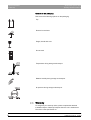
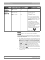
2.2 Legend
2.1.2
Formats and symbols used
The formats and symbols used in this document have the following
meaning:
Prerequisite
Requests you to do something.
1. First action step
2. Second action step
or
➢ Alternative action
Result
Identifies a reference to another
text passage and specifies its page
number.
● List
Identifies a list.
“Command / menu item”
Identifies commands, menu items
or quotations.
båÖäáëÜ
see “Formats and symbols
used [ → 7]”
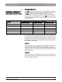
2.2 Legend
Year of manufacture
Year of manufacture
20XX
Safety symbols
"Warning of optical radiation" symbol
Fragment: Warning of optical radiation
Warning of injuries to eyes and skin in the vicinity of optical radiation.
"Warning of hand injuries" symbol
Fragment: Warning of hand injuries
Warning of hand injuries in the vicinity of devices with closing mechanical
parts.
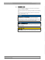
Description of the packaging
64 17 096 D3586
D3586.201.01.04.02
04.2014
7
2 General information
Sirona Dental Systems GmbH
2.3 Warranty
Operating Instructions inEos X5
Symbols on the packaging
Take note of the following symbols on the packaging:
Top
Top
Protect from moisture
Keep dry
Fragile; handle with care
Fragile
Do not stack
Do not stack
2
Temperature during storage and transport
Transport temperature -40 - +70
+70
-40
Relative humidity during storage and transport
Transport humidity 10 - 95
95
10
Air pressure during storage and transport
Transport air pressure 500 - 1060
1060
500
2.3 Warranty
To safeguard your warranty claims, please complete the attached
Installation Report / Warranty Passport when the unit is handed over.
Then fax it to the specified fax no.
8
64 17 096 D3586
D3586.201.01.04.02 04.2014
Sirona Dental Systems GmbH
3 Safety
Operating Instructions inEos X5
3.1 Basic safety information
3
Safety
3.1 Basic safety information
3.1.1
Prerequisites
NOTICE
Fragment everything excluding APOLLO DI
Important information on building installation
The building installation must be performed by a qualified expert in
compliance with the national regulations. DIN VDE 0100-710 applies in
Germany.
NOTICE
båÖäáëÜ
Restrictions regarding installation site
The system is not intended for operation in areas subject to explosion
hazards.
NOTICE
Do not damage the unit!
The unit can be damaged if opened improperly.
It is expressly prohibited to open the unit with tools!
3.1.2
Connecting the unit
Perform connection by following the directions given in the present
operating instructions.
Description
3.1.3
Connection of external equipment
If any equipment not approved by Sirona is connected, it must comply
with the applicable standards:
● EN 60 950 for information technology equipment, and
● EN 61 010-1 for laboratory equipment.
64 17 096 D3586
D3586.201.01.04.02
04.2014
9
3 Safety
Sirona Dental Systems GmbH
3.1 Basic safety information
Operating Instructions inEos X5
3.1.4
Maintenance and repair
As manufacturers of dental instruments and laboratory equipment, we
can assume responsibility for the safety properties of the unit only if the
following points are observed:
● The maintenance and repair of this unit may be performed only by
Sirona or by agencies authorized by Sirona.
● Components which have failed and influence the safety of the unit
must be replaced with original (OEM) spare parts.
Please request a certificate whenever you have such work performed. It
should include:
● The type and scope of work.
● Any changes made in the rated parameters or working range.
● Date, name of company and signature.
3.1.5
Changes to the product
Modifications to this unit which may affect the safety of the operator,
patients or third parties are prohibited by law!
3.1.6
Accessories
In order to ensure product safety, this device may be operated only with
original Sirona accessories or third-party accessories expressly approved
by Sirona. In particular, only the power cable supplied with the unit or the
corresponding original spare part may be used with the unit. The user
assumes the risk of using non-approved accessories.
Product safety of inEos X5
3.1.7
In case of damage
In case of noticeable malfunctions or damage, stop using the instrument
immediately and notify your dental depot or the manufacturer.
10
64 17 096 D3586
D3586.201.01.04.02 04.2014
Sirona Dental Systems GmbH
3 Safety
Operating Instructions inEos X5
3.2 Blue light radiation (UV)
båÖäáëÜ
3.2 Blue light radiation (UV)
A
Lamp
WARNING
Potentially hazardous optical radiation
Do not look directly at the lamp during operation, as eye damage can
result.
NOTICE
No reflective objects in the working area
Do not bring any reflective objects into the working area of the lamp.
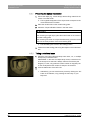
3.3 To be taken into account during automatic
operation
CAUTION
Risk of injury! / collision hazard!
During automatic operation there is a risk of injury/collision hazard as a
result of the swiveling movement of the articulated arm.
➢ Ensure that there are no objects and/or body parts on the work plate
(shaded area) during automatic operation.
64 17 096 D3586
D3586.201.01.04.02
04.2014
11
3 Safety
Sirona Dental Systems GmbH
3.4 Intended use
Operating Instructions inEos X5
3.4 Intended use
This system is used for 3D digitization of single tooth or complete jaw
models and impressions.
Intended use of the inEos X5_XM
If the unit is used for any usage purpose other than the one mentioned
above, it may be damaged.
Follow the operating instructions
Intended use also includes observing the present operating instructions
and the relevant maintenance instructions.
CAUTION
Follow the instructions
If the instructions for operating the unit described in this document are
not observed, the intended protection of the user may be impaired.
For the USA only
For the USA only
CAUTION: According to US Federal Law, this product may be sold only
to or by instruction of physicians, dentists, or licensed professionals.
3.5 Certification
CE mark
Machinery directive CE mark
This product bears the CE mark in accordance with the provisions of
Council Directive 2006/42/EC (machinery directive). As such, the
following standards apply: DIN EN ISO 12100:2011-03, DIN EN 610101:2011-07 and DIN EN 61326-1:2013-07.
CAUTION
CE mark for connected products
Further products which are connected to this unit must also bear the CE
mark. These products must be tested according to the applicable
standards.
Examples of CE mark for connected products:
Examples EN60950 + CAN/CSA
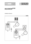
● EN 60950:1992 + A1:1993 + A2:1993 + A3:1995 + A4:1997 based on
IEC 60950
● CAN/CSA-C22.2 No.61010-1-04.
CSA mark
CSA mark
VDE mark
C
12
US
VDE mark
64 17 096 D3586
D3586.201.01.04.02 04.2014
Sirona Dental Systems GmbH
4 Technical description
Operating Instructions inEos X5
4.1 Design and function
4
Technical description
4.1 Design and function
The inEos X5 is designed as a desktop unit and consists of several
components (see Chapter "System components [ → 13]“). It is powered
from the standard local power network via an external power supply unit.
The unit is connected to a PC via a USB port. The PC must fulfill the
minimum requirements (see Chapter on "System requirements").
The PC serves both for controlling the inEos X5 and for displaying the
captured images by means of the user software.
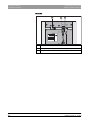
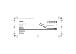
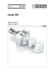
"inEos X5" consists of a base plate, a vertical unit and an articulated arm.
In addition, various accessories are included in the scope of supply of the
unit.
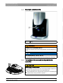
4.2.1
Components of the inEos X5
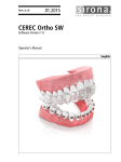
Front side
64 17 096 D3586
D3586.201.01.04.02
04.2014
A
Vertical unit
D
Ready LED
B
Articulated arm
E
Start button
C
Base plate
F
Scan element opening,
scan element
13
båÖäáëÜ
4.2 System components
4 Technical description
Sirona Dental Systems GmbH
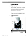
4.2 System components
Operating Instructions inEos X5
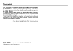
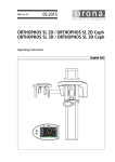
Rear side
A
B
M
C
24 V
USB
2.0
M6324649
S00106
Model-No. D3586
Merial-No. 00106
REF
6324649 2013
24 V
/ 120 W
Sirona Dental Systems GmbH
Fabrikstr. 31 D-64625 Bensheim
Made in Germany
14
A
Main switch
B
Supply voltage input (external power supply unit)
C
USB port
64 17 096 D3586
D3586.201.01.04.02 04.2014
Sirona Dental Systems GmbH
4 Technical description
Operating Instructions inEos X5
4.3 Technical data
4.3 Technical data
Model designation
inEos X5
Power supply line
via power supply unit:
INPUT: 100 - 240 V AC / 47- 63 Hz / 2.0 A max.
permissible line voltage fluctuations:
± 10% of nominal voltage
Overvoltage category II
Power consumption
150W
Ambient conditions
For indoor use
/ 6.25A max.
båÖäáëÜ
OUTPUT: 24V
Pollution degree 2
Temperature: 10°C – 35°C (50°F ~ 95°F)
Relative humidity: 30% – 75%
Air pressure: 700hPa – 1060hPa
Operating altitude: ≤ 2,000m
Transport and
storage conditions
Temperature: -40°C – +70°C (-40°F ~ 158°F)
Relative humidity: 10% – 95%
Air pressure: 500hPa – 1060hPa
Dimensions (WxHxD)
in mm
in inches
475 x 740 x 460 mm
18 ¾ x 29 ⅛ x 18 ⅛ in.
Weight
● without power supply unit and
accessories
39.6 kg (87.3 lbs)
Protection class
Class I device
Degree of protection against
ingress of water
Ordinary equipment (not protected)
Operating mode
Continuous operation with intermittent loading corresponding to the
laboratory mode of working.
Desktop unit
64 17 096 D3586
D3586.201.01.04.02
04.2014
15
4 Technical description
Sirona Dental Systems GmbH
4.4 System requirements
Operating Instructions inEos X5
Tests/approvals
This unit complies with the following requirements:
DIN EN 61 010-1: 2011 (safety)
DIN EN 61 326-1: 2006 (EMC)
DIN EN ISO 12 100: 2011 (risk management)
4.4 System requirements
A 64-bit inLab 4 PC is required to run this software. The hardware version
must be PC hardware version 2.0.1 or higher.
4.5 Electromagnetic compatibility
Observance of the following information is necessary to ensure safe
operation regarding EMC aspects.
Fragment: inEos X5
inEos X5 complies with the requirements for electromagnetic
compatibility (EMC) according to DIN EN 61326-1:2006-10.
inEos X5 is hereinafter referred to as "UNIT".
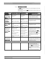
4.5.1
Electromagnetic emission
The UNIT is intended for operation in the electromagnetic environment
specified below.
The customer or user of the UNIT should make sure that it is used in such
an environment.
Emission measurement
Conformity
Electromagnetic environment – guidance
RF emissions according to CISPR 11
Group 1
The UNIT uses RF energy only for its internal
function. Therefore, its RF emissions are very low
and are not likely to cause any interference in
nearby electronic equipment.
RF emissions according to CISPR 11
Class B
Harmonics
according to IEC 61000-3-2
Class A
The UNIT is intended for use in all facilities,
including residential areas and those directly
connected to a public power supply, which also
provides electricity to buildings used for residential
purposes.
Voltage fluctuations/flicker according to Complies
IEC 61000-3-3
16
64 17 096 D3586
D3586.201.01.04.02 04.2014
Sirona Dental Systems GmbH
4 Technical description
Operating Instructions inEos X5
4.5 Electromagnetic compatibility
4.5.2
Interference immunity
The UNIT is intended for operation in the electromagnetic environment
specified below.
The customer or user of the UNIT should make sure that it is used in such
an environment.
Interference
immunity tests
DIN EN 61326-1 Test level Compliance level
Electromagnetic environment –
guidelines
Electrostatic
discharge (ESD)
according to IEC
61000-4-2
± 6 kV contact
± 6 kV contact
± 8 kV air
± 8 kV air
Floors should be wood, concrete, or
ceramic tile. If floors are covered with
synthetic material, the relative
humidity should be at least 30%.
Electrical fast
transient/burst
according to
IEC 61000-4-4
± 1 kV for input and output ± 1kV for input and
lines
output lines
± 2 kV for power supply
lines
± 2 kV for power supply
lines
Surge voltages
according to IEC
61000-4-5
± 1 kV differential mode
voltage
± 2 kV common mode
voltage
± 1 kV differential mode The quality of the line power supply
voltage
should be that of a typical commercial
or hospital environment.
± 2 kV common mode
voltage
Voltage dips, short
interruptions and
variations of the
power supply
according to IEC
61000-4-11
<5% UT for ½ period
(>95% dip of UT)
<5% UT for ½ period
(>95% dip of UT)
40% UT for 5 periods (60% 40% UT for 5 periods
dip of UT)
(60% dip of UT)
70% UT for 25 periods
(30% dip of UT)
<5% UT for 5sec. (>95%
dip of UT
Magnetic field of
3 A/m
power frequencies
(50/60 Hz) according
to IEC 61000-4-8
The quality of the line power supply
should be that of a typical commercial
or hospital environment.
Continued operation of the UNIT is
possible following interruptions of the
power supply, since the UNIT is
70% UT for 25 periods
powered by an uninterruptible power
(30% dip of UT)
supply backed up by a storage
<5% UT for 5sec. (>95% battery.
dip of UT
3 A/m
Power frequency magnetic fields
should be at levels characteristic of a
typical location in a typical commercial
or hospital environment.
Note: UT is the AC supply voltage prior to application of the test level.
Portable and mobile radio equipment
must not be used within the
recommended working clearance
from the UNIT and its cables, which is
calculated based on the equation
suitable for the relevant transmission
frequency.
Recommended working clearance:
64 17 096 D3586
D3586.201.01.04.02
04.2014
17
båÖäáëÜ
The quality of the line power supply
should be that of a typical commercial
or hospital environment.
4 Technical description
Sirona Dental Systems GmbH
4.5 Electromagnetic compatibility
Operating Instructions inEos X5
Interference
immunity tests
DIN EN 61326-1 Test level Compliance level
Electromagnetic environment –
guidelines
Conducted RF
interference
IEC 61000-4-6
3 Veff
150 kHz to 80 MHz
3 Veff
d= [1.2] √P
Radiated RF
interference
IEC 61000-4-3
3 V/m
80 MHz to 800 MHz
3 V/m
d= [1.2] √P
at 80 MHz to 800 MHz
3 V/m
800 MHz to 2.5 GHz
3 V/m
d= [2.3] √P
at 800 MHz to 2.5 MHz
where P is the nominal transmitter
output in watts (W) specified by the
transmitter manufacturer and d is the
recommended working clearance in
meters (m).
Field strengths from fixed RF
transmitters, as determined by an
electromagnetic site survey1 should
be less than the compliance level2 in
each frequency range.
Interference is possible in the vicinity
of equipment bearing the following
graphic symbol.
Remark 1
The higher frequency range applies at 80 MHz and 800 MHz.
Remark 2
These guidelines may not be applicable in all cases. The propagation of
electromagnetic waves is influenced by their absorption and reflection by
buildings, objects and persons.
1. Field strengths from fixed transmitters, such as base stations for radio
(cellular/cordless) telephones and land mobile radios, amateur radio,
AM/FM radio and TV broadcasts, cannot be predicted theoretically
with accuracy. An investigation of the location is recommended to
determine the electromagnetic environment resulting from stationary
RF transmitters. If the measured field strength in the location in which
the UNIT is used exceeds the applicable RF compliance level
specified above, the UNIT should be observed to verify normal
operation. If unusual performance characteristics are observed, it
may be necessary to take additional measures such as reorientation
or repositioning of the UNIT.
2. Over the frequency range 150kHz to 80 MHz, field strengths should
be less than 3 V/m.
18
64 17 096 D3586
D3586.201.01.04.02 04.2014
Sirona Dental Systems GmbH
4 Technical description
Operating Instructions inEos X5
4.5 Electromagnetic compatibility
4.5.3
Recommended working clearances
between portable and mobile RF
communication devices and the UNIT
Working clearances
The UNIT is intended for operation in an electromagnetic environment,
where radiated RF interference is checked. The customer or the user of
the UNIT can help prevent electromagnetic interference by duly
observing the minimum distances between portable and/or mobile RF
communication devices (transmitters) and the UNIT. These values may
vary according to the output power of the relevant communication device
as specified below.
d= [1.2] √P
d= [1.2] √P
d= [2,3] √P
0,01
0,12
0,12
0,23
0,1
0,38
0,38
0,73
1
1,2
1,2
2,3
10
3,8
3,8
7,3
100
12
12
23
båÖäáëÜ
Rated maximum output power of Working clearance according to transmission frequency [m]
transmitter
150 kHz to 80 MHz
80 MHz to 800 MHz
800 MHz to 2.5 GHz
[W]
For transmitters whose maximum nominal output is not specified in the
above table, the recommended working clearance d in meters (m) can be
determined using the equation in the corresponding column, where P is
the maximum nominal output of the transmitter in watts (W) specified by
the transmitter manufacturer.
Remark 1
An additional factor of 10/3 is applied when calculating the recommended
working clearance between transmitters in the 80 MHz to 2.3 GHz
frequency range in order to reduce the probability that a mobile/portable
communication device unintentionally brought into the patient area could
lead to interference.
Remark 2
These guidelines may not be applicable in all cases. The propagation of
electromagnetic waves is influenced by their absorption and reflection by
buildings, objects and persons.
64 17 096 D3586
D3586.201.01.04.02
04.2014
19
5 Transport to the installation site
Sirona Dental Systems GmbH
5.1 Transport and unpacking
Operating Instructions inEos X5
5
Transport to the installation site
5.1 Transport and unpacking
All Sirona products are carefully checked prior to shipment. Please
perform an incoming inspection immediately after delivery.
Transport and unpacking
1. Check the delivery note to ensure that the consignment is complete.
2. Check whether the product shows any visible signs of damage.
NOTICE
Damage during transport
If the product was damaged during transport, please contact your
carrying agent.
If return shipment is required, please use the original packaging for
shipment.
Transport without packaging
Fragment: Transport without packaging
CAUTION
Damage to the unit or risk of injury during transport without packaging
There is a danger of the unit falling down if it is grasped by its plastic
housing.
➢ The unit should always be carried by two persons.
➢ Do not grasp the unit by its plastic housing.
➢ Always grasp the unit by its chassis next to its feet.
20
64 17 096 D3586
D3586.201.01.04.02 04.2014
Sirona Dental Systems GmbH
5 Transport to the installation site
Operating Instructions inEos X5
5.2 Installation site
5.2 Installation site
The unit is designed for desktop use and requires a level footprint of
approx. 70 x 60cm for installation.
No special requirements exist regarding the ventilation at the installation
site.
Make sure that the specified operating conditions are observed (see
section "Technical data [ → 15]“).
NOTICE
Install inEos X5 in a protected area
3D image acquisition may be adversely affected by bright light.
NOTICE
ON/OFF switch on rear of unit
Set the inEos X5 up so that the ON/OFF switch on the rear of the unit is
readily accessible.
CAUTION
Risk of injury
When assembled, fingers must not be inserted beneath the unit.
64 17 096 D3586
D3586.201.01.04.02
04.2014
21
båÖäáëÜ
Set the inEos X5 up so that it is not located directly in the beam path of
an extreme light source and not exposed to direct sunlight.
6 Initial startup
Sirona Dental Systems GmbH
6.1 Putting the inLab 4 PC into operation
Operating Instructions inEos X5
6
Initial startup
6.1 Putting the inLab 4 PC into operation
6.1.1
6.1.1.1
Startup prerequisites
Required accessories
Supplied parts:
● inLab PC with power cable
● Keyboard
● Mouse
● 2x DVI VGA converters
● inEos X5,
● inEos power supply unit
● Power cable
● USB cable for connecting the inEos X5 to the PC.
22
64 17 096 D3586
D3586.201.01.04.02 04.2014
Sirona Dental Systems GmbH
6 Initial startup
Operating Instructions inEos X5
6.1 Putting the inLab 4 PC into operation
Also required:
● VGA/DVI monitor including VGA/DVI cable (not included in scope of
supply)
CAUTION
Image may not display
Please note the required minimum monitor resolution of 1280 x 1024 at
70Hz. Please refer to the technical documentation of the monitor for the
correct resolution and frame rate settings.
Recommendation:
● Sirona inLab system PC monitor, Order No.: 60 42 548 D3446
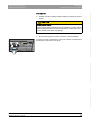
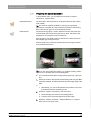
båÖäáëÜ
In order to connect a VGA monitor, screw one of the two converters onto
the left DVI port as shown in the photo.
MSI
64 17 096 D3586
D3586.201.01.04.02
04.2014
23
6 Initial startup
Sirona Dental Systems GmbH
6.1 Putting the inLab 4 PC into operation
6.1.1.2
Operating Instructions inEos X5
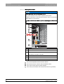
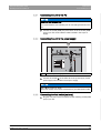
Making connections
NOTICE
Do not connect or switch on the inEos X5 yet!
First, connect the PC to the monitor, keyboard, and mouse.
Follow the instructions in this document exactly in order to successfully
perform start-up of your device.
You must install the user software prior to connecting the device to the
PC.
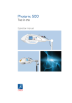
A
B
C
D
inEos X5
E
F
A
USB license stick
B
USB for inEos X5
C
Keyboard/mouse
Alternatively: Connection via USB
D
USB for inEos X5 foot control
E
Optional: Audio output
F
Monitor
1. Connect the keyboard and the mouse to the PC.
2. Connect the monitor to the PC with the VGA/DVI cable.
3. Turn on the monitor and PC power supplies.
4. Turn on the power switch on the rear panel of the PC (if present).
24
64 17 096 D3586
D3586.201.01.04.02 04.2014
Sirona Dental Systems GmbH
6 Initial startup
Operating Instructions inEos X5
6.1 Putting the inLab 4 PC into operation
6.1.2
Safety
inLab 4 PC is equipped with Windows 7 Professional (64-bit). The
Windows Firewall is activated. The software Microsoft Security Essentials
is also pre-installed by default. Please activate the automatic update
function in the settings of this software for optimal protection.
CAUTION
Damage to the system and data loss:
If you exchange files and programs with other PC systems and/or
operate this PC in a network (LAN or Internet), damage may be caused
by software viruses.
➢ Activate the "Automatic Updates" function of Microsoft Security
Essentials.
➢ Activate the "Automatic Updates“ function of Windows 7.
6.1.3
64 17 096 D3586
D3586.201.01.04.02
04.2014
båÖäáëÜ
➢ Run backups of all your important files at regular intervals.
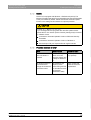
Possible sources of error
Error
Possible cause
Corrective action
PC does not start
when the button is
pressed.
If the PC has a power Turn the power switch
switch on its rear
on (if present).
panel, this switch may
possibly be switched
off.
No image appears on
the monitor even
though all connections
have been made.
The resolution and
Use a monitor that
frequency of the
meets the minimum
monitor being used do requirements.
not meet the minimum
requirements
(1280x1024; 70Hz).
25
6 Initial startup
Sirona Dental Systems GmbH
6.2 Installing the software
Operating Instructions inEos X5
6.2 Installing the software
NOTICE
Fragment: Initial installation
Initial installation without inEos X5
Perform the initial installation of the software without connecting inEos
X5.
The software requires the 2.00 firmware version of the license stick.
Update the firmware version if necessary. For additional information, refer
to the "License manager" section in the inLab SW user manual.
Fragment: inEos X5_XM firmware 2.0
You need a inLab 4 PC for the software.
Prerequisite
Use the version of the license manager provided with this version to
import licenses from the license certificate provided.
NOTICE
Administrator rights
Installation only with administrator rights
You must have administrator rights on the PC on which you want to
install the software!
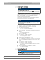
✔ The license stick firmware is available in version 2.00.
✔ The PC is powered up and all programs are terminated.
1. Insert the DVD in the DVD drive.
The setup program starts automatically.
2. If this is not the case, run the "Setup.exe" file in the root directory of
the DVD.
The installation wizard opens.
3. Click on the "OK" button.
4. In the next dialog, click the "Next" button.
The license agreement is shown.
5. Read through the license agreement carefully.
6. If you accept the license agreement, then activate the "I accept the
terms in the license agreement" option button and click the "Next"
button.
7. In the next dialog, click the "Next" button.
8. In the next dialog, click the "Install" button.
The program continues the installation routine. This may take
several minutes.
9. Click the "Finish" button once installation is complete.
The software is installed.
6.3 Connecting the unit
NOTICE
Switching the PC off
Switch the PC off before connecting the inEos X5.
26
64 17 096 D3586
D3586.201.01.04.02 04.2014
Sirona Dental Systems GmbH
6 Initial startup
Operating Instructions inEos X5
6.3 Connecting the unit
6.3.1
Connecting the unit to the PC
NOTICE
Install the user software first!
You must install the user software prior to connecting the device to the
PC.
➢ Connect the socket (USB port) of the inEos X5 to the socket (USB
port) of your PC via the interface cable included in the scope of
supply.
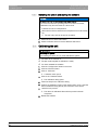
6.3.2
Connecting the unit to the power supply
M
24 V
båÖäáëÜ
A
USB
2.0
M6324649
S00106
Model-No. D3586
Merial-No. 00106
REF
6324649 2013
24 V
/ 120 W
Sirona Dental Systems GmbH
Fabrikstr. 31 D-64625 Bensheim
Made in Germany
A
Socket for power supply
➢ Connect the socket (A) of the inEos X5 to the power supply via the
power supply unit included in the scope of supply.
NOTICE
Use a grounded power outlet
The power supply unit must be connected to a grounded power outlet.
6.3.3
Connecting the foot switch (optional)
➢ Plug the connector of the foot switch into the matching socket (USB
port) of your PC.
Fragment: Connecting the foot switch
64 17 096 D3586
D3586.201.01.04.02
04.2014
27
6 Initial startup
Sirona Dental Systems GmbH
6.4 Calibrating the unit
Operating Instructions inEos X5
6.3.4
Switching the unit on and starting the software
NOTICE
Let unit dry off after storage
Do not put the unit into operation at low temperatures!
If you move the unit to the operating site from a cold environment,
condensation may form and result in a short circuit.
✔ Install the unit at room temperature.
➢ Wait until the unit has reached room temperature and is absolutely
dry.
The unit is dry and can be put into operation.
1. Switch the unit on at the main switch.
2. Start the software at the PC via the Windows start menu.
6.4 Calibrating the unit
IMPORTANT
Calibrating the system
After installing the inEos X5, you must calibrate the system.
✔ The inEos X5 is switched on.
✔ The jaw model supplied for calibration is ready.
✔ You have restarted the software.
Procedure
1. Click the "Configuration" button in the menu.
2. Click the "Devices" button.
3. Click on "inEos X5".
A selection menu opens.
4. Click on the "Calibrate" button.
The calibration dialog opens.
5. Follow the steps in the calibration dialog.
6. Position the calibration model on the rotation disk in such a way that
the front teeth are facing directly in the direction of the device.
7.
Start the scan process.
The device is calibrated. Wait until the process has been
completed.
8. Restart the software.
28
64 17 096 D3586
D3586.201.01.04.02 04.2014
Sirona Dental Systems GmbH
6 Initial startup
Operating Instructions inEos X5
6.5 Updating the firmware
6.5 Updating the firmware
In order to update the inEos X5 firmware, proceed as follows:
1. In the inLab SW, click on "Configuration" in the menu bar.
2. Click on the "Devices" icon.
3. Click on the icon of inEos X5.
4. Click on "Update Firmware".
5. Switch inEos X5 off at the main switch.
6. Then simply proceed as prompted by the inLab software.
The inEos X5 firmware will be updated. The percentage of
completed progress is displayed.
IMPORTANT
During the firmware update, ensure that the unit is not disconnected
from the power supply.
7. Once the update is complete, confirm the message with "OK" and
switch off the inEos X5.
8. Turn the inEos X5 back on.
9. Click on "Continue" in order to exit the configuration and continue with
the inLab SW.
64 17 096 D3586
D3586.201.01.04.02
04.2014
29
båÖäáëÜ
Do not disconnect the unit from the power supply
7 Controls and displays
Sirona Dental Systems GmbH
7.1 Controls on the inEos X5
Operating Instructions inEos X5
7
Controls and displays
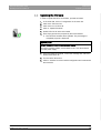
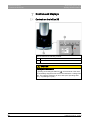
7.1 Controls on the inEos X5
inEos X5 features the following controls:
A
Start key
B
CC
Fragment: Stopping motor movements
CAUTION
Stopping motor movements
By pressing and holding the Start key (A), all movements of the motor
are immediately stopped and the motors are switched to a voltage-free
state. The unit then switches to an error state (see "Operating state
LED [ → 31]LED lights up red").
30
64 17 096 D3586
D3586.201.01.04.02 04.2014
Sirona Dental Systems GmbH
7 Controls and displays
Operating Instructions inEos X5
7.2 Operating state LED
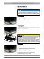
7.2 Operating state LED
The LED shows the operating status of the unit:
NOTICE
Once the unit is switched on, the LED must light up in one of the
following colors. Should this not be the case, this indicates a unit defect,
which must be eliminated prior to further use.
LED lights up green
The unit is ready for operation.
The articulated arm will move only in case of user interaction in the
software or if the Start key is actuated.
båÖäáëÜ
Fragment: Green inEos X5 LED
LED lights up yellow
An automatic acquisition process has been started; the arm is already
moving or is about to start moving.
Fragment: Yellow inEos X5 LED
Fragment: Risk of injury
CAUTION
Risk of injury!
Do not place any part of your body either wholly or partially in the
working area of the articulated arm in this operating state!
Ensure that there are no objects and/or body parts on the work plate
(shaded area) during automatic operation. Otherwise this creates a
collision hazard as a result of the swiveling movement of the articulated
arm.
LED lights up red
Error state.
Causes may include:
● Activation of safety light barrier on the scan element
● Pressing and holding the Start key
● Malfunctioning of drives
The articulated arm will not move in this operating state.
Fragment: Red inEos X5 LED
Proceed as prompted by the inLab software.
64 17 096 D3586
D3586.201.01.04.02
04.2014
31
8 Switching the system on
Sirona Dental Systems GmbH
Operating Instructions inEos X5
8
Switching the system on
NOTICE
Let unit dry off after storage
Do not put the unit into operation at low temperatures!
If you move the unit to the operating site from a cold environment,
condensation may form and result in a short circuit.
✔ Install the unit at room temperature.
➢ Wait until the unit has reached room temperature and is absolutely
dry.
The unit is dry and can be put into operation.
Switching the inEos X5 on
Switching the system on
1. Switch on the PC.
2. Switch the inEos X5 on at the main switch.
Starting the software
➢ Start the software at the PC via the Windows start menu.
32
64 17 096 D3586
D3586.201.01.04.02 04.2014
Sirona Dental Systems GmbH
9 Performing 3D acquisition
Operating Instructions inEos X5
9.1 General
9
Performing 3D acquisition
9.1 General
9.1.1
Acquisition methods
Three methods are available for acquiring scans with the inEos X5:
● Automatic jaw scan
– For all tasks
– Especially for large, complex tasks or tasks with high accuracy
requirements
● Free jaw scan
båÖäáëÜ
– For simple tasks
– For free detail scans under various angles
● Individual stump scan
– For the measurement of one or more single tooth stumps
– For single restorations without consideration of the proximal
contacts or the antagonist
Tip: You can execute several scan methods in sequence. You can omit a
scan method if, for example, it is either not suitable or is not required for
your model.
IMPORTANT
Perform the individual stump scans either completely prior to or after the
automatic and/or free scans.
It is not possible (for example) to initially perform an automatic scan,
then carry out a scan of individual stumps, and, finally, to change back
to automatic mode once again.
Tip: For stump model tasks, first take the scans of the prepared stumps.
Then add automatic and/or free scans. In this way, you can reduce the
processing time.
9.1.2
Scan modes
You can take the scans using two modes. You can switch between the
modes using the "Mode" function.
"Single Exposure"
Use the "Single Exposure" mode for scans of models with no special
requirements in terms of the brightness settings for the exposure
(standard value).
64 17 096 D3586
D3586.201.01.04.02
04.2014
33
9 Performing 3D acquisition
Sirona Dental Systems GmbH
9.1 General
Operating Instructions inEos X5
"Multiple (HDR) Exposure"
The HDR ("high dynamic range") mode captures situations requiring a
large dynamic range (differences in brightness) during the exposure.
This mainly concerns material mixes, for example:
● Dark plaster
● Abutments covered with Optispray
● When using scan wax
● When measuring scanbodies
● When capturing silicon impression trays with several multi-colored
impression materials
inEos X5 captures these situations using multiple exposure, so that every
part of the surface is measured with the optimal exposure setting.
Accordingly, the scan takes longer.
9.1.3
Scan options
You can use the free scan option to capture models and impressions.
Acquiring impressions
1. Click on the "Options" button.
2. Click on the "Toggle Impression Scan" button.
The icon for the impression scan is displayed in the live image.
3. Select the image catalog.
4. Start the free acquisition procedure.
9.1.4
Model options
For all image catalogs (with the exception of the buccal registration), it is
possible to specify for each new case whether the palate areas are taken
into account for calculating the model or automatically ignored.
Complete Reconstruction
For this option, the complete model is calculated with the palate/model
plate area. This option increases the calculation time for the model.
34
64 17 096 D3586
D3586.201.01.04.02 04.2014
Sirona Dental Systems GmbH
9 Performing 3D acquisition
Operating Instructions inEos X5
9.1 General
Reduced Reconstruction
For this option, the model is calculated as a dental arch without the palate/
model plate area. This option reduces the calculation time for the model.
Tip: Select "Reduced Reconstruction" for all work which does not involve
the palate areas, or if areas of the model plate were also scanned. This
also helps to speed up the model calculation process.
Change standard setting for the model options
You can change the standard value for the reconstruction mode in the
global settings of "Complete Reconstruction" to "Reduced
Reconstruction".
The mode can be changed at "Configuration" / "Devices" / "inEos X5" /
"Configure Device". You can activate the relevant mode in the "Standard
Mode for model calculation" field.
9.1.5
Scan models and impressions
Materials
You can scan all materials that correspond to the following criteria:
● Non-reflecting
● Non-transparent
● No transparent parts
● Not highly absorbent
(e.g. heavily colored plasters, scannable impression materials)
IMPORTANT
Unscannable materials generate artifacts or gaps in the image.
Tip: When using materials that do not meet these criteria, you must
powder the affected areas. Otherwise the measuring accuracy will be
heavily influenced.
The following is suitable for this purpose, for example: CEREC Optispray
(REF 61 44 179)
For scanning with inEos X5, we recommend using CEREC Stone BC
plaster (REF 62 37 502).
Saw-cut models
● When preparing saw-cut models, be careful not to grind off the single
stump segments. Place the model next to the stumps so that the
inEos X5 can properly capture these areas.
Saw-cut etc.
● Create only a slight fluting below the preparation margin.
64 17 096 D3586
D3586.201.01.04.02
04.2014
35
båÖäáëÜ
The relevant reconstruction mode set as standard will be selected in all
future cases in every image catalog. However, this can still be individually
amended.
9 Performing 3D acquisition
Sirona Dental Systems GmbH
9.2 Starting the unit/standby mode
Operating Instructions inEos X5
9.1.6
Autofocus
inEos X5 features automatic focusing.
As soon as the object stops moving, the image is automatically focused
both in the automatic and in the manual mode.
Fragment: inEos X5 autofocus
9.1.7
Deleting images
You can delete individual scans by marking them with the left mouse
button and dragging them into the recycle bin.
You also can delete an entire image catalog (see inLab SW Operator's
Manual).
9.1.8
Operation via foot switch
As an alternative to the Start button of the inEos X5, you also can use the
optionally available foot switch (REF 63 10 449) to start and end scanning
processes in the respective scanning mode.
➢ Plug the connector of the foot switch into the matching socket (USB
port) of your PC.
Fragment: Connecting the foot switch
9.2 Starting the unit/standby mode
The inEos X5 automatically starts (if the main switch is turned on) as soon
as you switch to the acquisition phase of the inLab software.
You can set the inEos X5 to standby mode and wake it up manually.
➢ To do this, click the inEos X5 icon in the bottom left window are of the
inLab software.
Set the inEos X5 to standby mode Activate the inEos X5
Tip: Switch off the inEos X5 via the main switch only if the inEos X5 is in
standby mode (projection lamp switched off and articulated arm in
parking position) or if no scan process has been started.
Fragment: inEos X5 tip
Shutdown during a running scan process causes considerable delays
when the unit is restarted.
9.3 Automatic jaw scan
Capture the model situation fully automatically in the "Capture Jaw"
mode.
● For all tasks.
● Especially for large, complex tasks or tasks with especially high
accuracy requirements
36
64 17 096 D3586
D3586.201.01.04.02 04.2014
Sirona Dental Systems GmbH
9 Performing 3D acquisition
Operating Instructions inEos X5
9.3 Automatic jaw scan
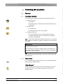
9.3.1
Preparing the optical impression
In the automatic scan, you can select from the options "Capture
Reduced" or "Capture Area".
"Capture Reduced":
The entire jaw is scanned based on a standard sequence with a lower
level of detail.
Tip: This mode is especially suitable for scanning an unprepared
opposite jaw. It provides all of the information required for the following
steps. Hard-to-scan gaps are not automatically closed.
"Capture Area":
The area scanning option is used to define the areas in which the scan
is automatically performed with a high level of detail. The areas of the
preparations are usually the ones involved here.
All other areas of the model are scanned with a lower degree of detail
using a standard sequence.
Model holding plates
Tip: If you are using partial jaw models (e.g. quadrant models), position
these on the outer edge of the model holding plate.
✔ You have selected the desired image catalog (lower jaw, upper jaw,
etc.).
1. Fasten the model to the supplied model holding plate using the Blue
Tack filling material. The labial side must face the straight edge of the
plate.
or
➢ Alternatively, you can use the parallel vise provided. In this case,
the labial side faces the fastening screw.
2. Select the "Capture Jaw" button in the Scan menu.
The articulating arm moves to the loading position.
A section of the scan area appears in the live image.
3. Select the "Capture Complete", "Capture Reduced", or "Capture
Area" option in the Scan menu.
64 17 096 D3586
D3586.201.01.04.02
04.2014
37
båÖäáëÜ
All of the gaps in the digital model are closed in the scanned areas via
the intelligent gap closing technique.
9 Performing 3D acquisition
Sirona Dental Systems GmbH
9.3 Automatic jaw scan
Operating Instructions inEos X5
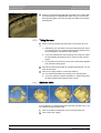
4. Position the model holding plate with the model on the rotation disk
of the articulating arm. IMPORTANT: When doing so, ensure that
areas including teeth or the alveolar ridge are visible to the camera
(see diagram).
9.3.2
Taking the scan
1. Start the scan by pressing the Start button on the inEos X5 once.
or
➢ Alternatively, you can start the scan by pressing the return key on
your keyboard once, by actuating the foot switch (optional) once,
or by actuating the "Ok" button in the software.
If you have selected the "area scanning" scan mode, the inEos
X5 automatically generates five to six scans from the occlusal
aspect.
On completion of the overview scans, the model preview appears
and a selection dialog opens.
2. Press and hold the mouse button to mark the prepared area. You can
mark several areas.
3. Click on the "Apply" button to confirm the selection.
You can discard the selection by clicking on the "Reset" button.
If you have selected "Capture Complete" or "Capture Reduced",
the inEos X5 starts the automatic scan process.
9.3.3
Guideline editor
If the guideline is not automatically found after the overview scan, it can
be corrected via the guideline editor.
1. Click on the balls and drag them to the correct jaw ridge line.
2. Then confirm with "Apply".
38
64 17 096 D3586
D3586.201.01.04.02 04.2014
Sirona Dental Systems GmbH
9 Performing 3D acquisition
Operating Instructions inEos X5
9.4 Free scans
9.3.4
Starting the automatic detail scan
Following an automatic scan, individual scans can be released by clicking
the mouse.
1. Position the virtual model so that the area of interest is well visible.
2. Start the automatic detail scan by double-clicking on the area of
interest.
The inEos X5 positions the model in the scanning position with
the rotation arm and automatically starts the scan. The image is
automatically registered in the virtual model.
Tip: If no scans can be released, try changing the angle of the model
slightly.
9.4 Free scans
In the "Capture Free" mode, you can capture the model situation fast,
manually and in a controlled manner for simple tasks.
Moreover, you can scan e.g. areas that may not be sufficiently captured
in the automatic mode with detail scans.
● For simple tasks
● For additional scans at different angles
9.4.1
Preparing the optical impression
✔ You have selected the desired image catalog (lower jaw, upper jaw
Fragment: Preparing a scan with the inEos X5
etc.).
Tip: Take special care to select the right image catalog for detail
scans.
1. Fasten the model to the supplied model holding plate with Blue Tack.
The labial side must face the straight edge of the plate.
or
➢ Alternatively, you can use the parallel vise provided. In this case,
the labial side faces the fastening screw.
2. Position the model holding plate used with the spherical model
holder.
3. Select the "Capture Free" button in the Scan menu.
The articulating arm moves to its parking position.
A section of the scan area appears in the live image.
Green crosshairs appear in the live image.
64 17 096 D3586
D3586.201.01.04.02
04.2014
39
båÖäáëÜ
Fragment: inEos X5 free scan
9 Performing 3D acquisition
Sirona Dental Systems GmbH
9.4 Free scans
Operating Instructions inEos X5
9.4.2
Automatic and manual release in the "free scan" mode
When working in the "Capture Free" mode, there are several possibilities
for releasing scans.
Capture Manual
"Capture Manual" is the standard inEos X5 mode.
➢ Double-click the Start button.
or
➢ Alternatively, you can use the return key on your keyboard or the
"Capture Manual" button below the live preview.
An individual scan is taken with each release.
Capture Auto
1. Select the "Capture Auto" mode in the Scan menu.
or
➢ Alternatively, you can click on the Start button of the inEos X5.
The crosshairs in the live image turn green.
2. Start the scans by clicking the "Ok" button in the software.
or
➢ Alternatively, you can click the Start button of the inEos X5 or
press the Return key on your keyboard.
The crosshairs in the live image turn blue.
After the model has been moved or tilted and is again in the rest
position, exposures are automatically released.
3. Single-click the Start button of the inEos X5 to interrupt/end the
automatic release mode.
The crosshairs in the live image turn green.
9.4.3
Taking a free scan (without previous automatic scans)
1. Align the model.
The model is aligned horizontally.
As many teeth as possible are visible in the live image.
2. Let the model rest and wait until the autofocus has focused the
model.
3. Start the acquisition process with automatic or manual release
A scan is generated.
4. Add additional scans from adjacent areas: Move the model freely in
the working area until you have reached the next acquisition position.
As soon as the model stops moving, the camera is automatically
released or is manually released by a double-click on the Start button.
You can tilt the model on the shifting plate by up to 40°.
NOTICE! The new image must overlap approximately 30-50% of the
previous image.
5. Repeat step 4 until all of the required scans have been taken.
40
64 17 096 D3586
D3586.201.01.04.02 04.2014
Sirona Dental Systems GmbH
9 Performing 3D acquisition
Operating Instructions inEos X5
9.5 Rotational scans
9.4.4
Taking a free detail scan
1. Align the model.
The areas in which information is missing in the digital model
preview can be seen in the live image.
2. Let the model rest and wait until the autofocus has focused the
model.
3. Start the acquisition process with automatic or manual release
4. Add additional scans from adjacent areas: Move the model freely in
the working area until you have reached the next acquisition position.
As soon as the model stops moving, the camera is automatically
released or is manually released by a double-click on the Start button.
You can tilt the model on the shifting plate by up to 40°.
NOTICE! The new image must overlap approximately 30-50% of the
previous image.
5. Repeat step 4 until all of the required scans have been taken.
9.5 Rotational scans
Use the rotational scan mode to acquire single tooth stumps from all
sides.
● For the surveying of single tooth stumps
● For single restorations without consideration of the proximal contacts
or the antagonist
IMPORTANT
Perform the rotational scan either completely prior to or after the
automatic and/or free scans.
Various scan options are available in the "Capture Rotation" mode.
Button
Scan option
● Individual stump scan tilted
● For scanning all standard individual stumps
Tip: Change the angle for the individual stump scan for scanning stumps that
are heavily undercut or for scanning abutments by moving the slider. You can
adjust the angle of incidence from 45° to 105° individually in 5° increments in
accordance with the relevant situation. An angle of 60° is recommended as the
standard value for all standard individual stumps.
● Multiple-stump scan
● For scanning up to 4 stumps at the same time
Tip: The difference in height between the stumps in the group being scanned should
not exceed 10 mm in relation to the assembly plate. If this cannot be avoided, scan
the stumps using the individual scan option.
If the stumps are not made from the same type of plaster, activate the HDR mode.
64 17 096 D3586
D3586.201.01.04.02
04.2014
41
båÖäáëÜ
A scan is generated.
9 Performing 3D acquisition
Sirona Dental Systems GmbH
9.5 Rotational scans
Operating Instructions inEos X5
9.5.1
Preparing the optical impression
1. Secure the object (e.g. a tooth stump) with the filling material in the
center of a model holder.
The longitudinal alignment of the object must correspond to the
model holder's axis of rotation.
2. Place the model holder on the model holding plate.
3. Select the "Capture Rotation" button in the Scan menu.
IMPORTANT
When scanning a single object, place the model holder in the center of
the model holding plate.
When scanning more than one object simultaneously, place the model
holders in the outer positions of the model holding plate.
The articulating arm moves to the loading position.
4. Fasten the model holding plate using the objects on the articulated
arm.
9.5.2
Taking a rotational scan
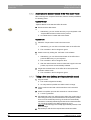
1. Select the scan type (individual stump scans at 60°, 75°, or multiplestump scan) in the Scan menu.
IMPORTANT: In the case of multiple-stump scans, ensure that one
of the stumps to be scanned is always visible to the camera (see
diagram). For this, only position the same number of magnetic pots
on the model plate as the number of stumps to be scanned.
2. Click the Start button of the inEos X5.
or
➢ Alternatively, you can start the scan process by clicking the "Ok"
button in the software, or by pressing the return key on your
keyboard.
42
64 17 096 D3586
D3586.201.01.04.02 04.2014
Sirona Dental Systems GmbH
9 Performing 3D acquisition
Operating Instructions inEos X5
9.6 Acquiring a buccal registration
9.6 Acquiring a buccal registration
You can secure the model using the articulator plate which is available as
an option (see "Using the articulator plate [ → 48]“).
Fragment: Using the articulator plate
✔ You have selected the "Buccal" image catalog.
✔ The image catalogs of the jaw and of the opposite jaw contain images
with buccal sections at a position next to or directly on the
preparation.
✔ In the buccal image, both jaws must be moved to the centric jaw
relation and an exposure taken that records both jaws at the same
time.
✔ Tip: The model can be left in the articulator.
✔ Alternatively, it is recommended to fasten the model e.g. with wax
1. Select the "Table free" exposure mode.
2. Position the model under the camera in such a way that one jaw is
located in each half of the image.
3. Wait until the autofocus has focused the model.
4. Release an exposure. In most cases, one exposure is sufficient.
64 17 096 D3586
D3586.201.01.04.02
04.2014
43
båÖäáëÜ
and manually hold it under the camera. The model should be
supported on the working area.
10 Regular function test of the light barrier and the Start key
Sirona Dental Systems GmbH
Operating Instructions inEos X5
10
Regular function test of the light barrier and
the Start key
The light barrier and Start key function test must be performed by a fully
qualified specialist every 12 months and the results of which must be
documented.
CAUTION
Risk of injury!
Do not place any part of your body either wholly or partially in the scan
element opening!
Function test 1
✔ The unit is switched on at the main switch.
➢ Place an object as thick as a finger (e.g. a felt-tip pen) in the scan
element opening in the operating mode.
Operating state LED
Test result
The operating state LED changes
from green to red.
Nominal state
The operating state LED stays
green or yellow.
Error state
Light barrier functioning.
Call customer service.
Function test 2
✔ The unit is switched on at the main switch.
1. Roll up a strip of paper to form a paper roll with a diameter of 45 to 70
mm.
2. Place the paper roll in the opening on the bottom of the vertical unit
in the operating state.
44
Operating state LED
Test result
The operating state LED changes
from green to red.
Nominal state
The operating state LED stays
green or yellow.
Error state
Light barrier functioning.
Call customer service.
64 17 096 D3586
D3586.201.01.04.02 04.2014
Sirona Dental Systems GmbH
10 Regular function test of the light barrier and the Start key
Operating Instructions inEos X5
Function test 3
✔ The unit is switched on at the main switch.
✔ The power LED lights up green.
➢ Press and hold the Start key.
Operating state LED
Test result
The operating state LED changes
from green to red.
Nominal state
The operating state LED stays
green or switches to yellow.
Error state
Stop function guaranteed.
Call customer service.
båÖäáëÜ
No maintenance other than the light barrier function tests described
above must be performed on the inEos X5 .
64 17 096 D3586
D3586.201.01.04.02
04.2014
45
11 Cleaning and care
Sirona Dental Systems GmbH
11.1 Cleaning the outer surface
Operating Instructions inEos X5
11
Cleaning and care
11.1 Cleaning the outer surface
Clean the outer surfaces at regular intervals with a mild, commercially
available cleaning agent.
11.2 Protection against medicaments
Due to their high concentrations and the substances they contain, many
medicaments can dissolve, etch, bleach or discolor surfaces.
NOTICE
Damage to the surface
Clean the surface immediately with a moist cloth and a cleaning agent.
11.3 Cleaning the optics
The 3D camera system is a very sensitive optical device and must be
handled with the utmost care. It is not usually necessary to clean the
optical surfaces as these are located inside the device.
If, as an exception, cleaning is required, you can clean the optical
surfaces.
✔ The unit is switched on at the main switch.
1. Switch to the scan phase in the inLab software.
2. Select "Capture Free".
3. Place a sheet of paper on the work surface so that it is illuminated by
the blue projector lamp.
The auto-focus function moves the scan element into the lowest
position
Wait until the auto-focus movement has been completed.
4. Switch the unit off at the main switch.
5. Secure the main switch so that it cannot be switched back on
inadvertently (e.g. by another person).
The blue light is no longer emitted from the opening of the
scanning element.
You can view the scanning elements using a mirror or from
directly below (camera lens and projection lens).
6. Attempt to blow away the dirt. Use conventional photo bellows for
this.
7. If further cleaning is required, clean the optical surfaces using a dust
and lint-free soft cotton swab and a little ethanol (standard alcohol for
cleaning) or acetone.
8. Switch on the inEos X5 at the main switch and restart the software.
46
64 17 096 D3586
D3586.201.01.04.02 04.2014
Sirona Dental Systems GmbH
12 Accessories
Operating Instructions inEos X5
12
Accessories
The inEos X5 is supplied with the following accessories.
● Ball joint model holder (1x) for accommodating the model plate
magnetic coupling or the parallel vise magnetic coupling for free
scans.
Fragment: inEos X5 accessories
● Model plate magnetic coupling (4x) for attaching models or
impressions to the ball joint model holder or the articulated arm of the
inEos X5 during free or automatic scans. Please use Blue filling
material when attaching the model.
● Parallel vise magnetic coupling for attaching models or impressions
to the ball joint model holder or the articulated arm of the inEos X5
during free or automatic scans.
● Magnetic pot D50 (2x) for scanning larger stump areas. Please use
Blue filling material.
● Power cable (2x) for inEos X5 and PC
● inEos X5 power supply unit (1x)
● USB cable (1x)
● Blue filling material (1x) for attaching models, impressions or
individual stumps.
● Cerec Stone BC (2x)
● inEos X5 axis calibration set (1x)
● Monitor (optional, 1x, REF 60 42 548) incl. power cable (1x)
● Open inLab license voucher (optional, 1x) for activating the Open
inLab license.
● USB foot control (optional, 1x, REF 63 01 449) for starting scan
processes
● Articulator plate (optional, 1x, REF, 63 72 705) for placing articulators
in the scan area during buccal scans.
64 17 096 D3586
D3586.201.01.04.02
04.2014
47
båÖäáëÜ
● Magnetic pot D30 (8x) for scanning individual stumps. Please use
Blue filling material.
12 Accessories
Sirona Dental Systems GmbH
12.1 Using the articulator plate
Operating Instructions inEos X5
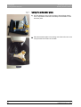
12.1 Using the articulator plate
1. Use the adjusting screw to set the height of the articulator plate in
such a way that the model lies horizontally in the articulator on the
articulator plate.
2. Place the articulator plate in the working area of the inEos X5 in such
a way that the buccal scan can be taken.
48
64 17 096 D3586
D3586.201.01.04.02 04.2014
Sirona Dental Systems GmbH
13 Disposal
Operating Instructions inEos X5
13
Disposal
Your product is marked with the adjacent symbol. Within the European
Economic Area, this product is subject to Directive 2002/96/EC as well as
the corresponding national laws. This directive requires environmentally
sound recycling/disposal of the product. The product must not be
disposed of as domestic refuse!
Environmentally sound disposal
Please observe the disposal regulations applicable in your country.
Disposal procedure
Prior to disassembly / disposal of the product, it must be fully prepared
(cleaned / disinfected / sterilized).
When disposing of equipment permanently, please proceed as follows:
In Germany:
To initiate return of the electrical device, please send a disposal order to
"enretec GmbH".
1. You can find a form for placing a disposal order on the company's
homepage (www.enretec.de) under the menu item "Entsorgung
elektrischer und elektronischer Geräte" (Disposal of electric and
electronic devices). The form can either be downloaded or completed
online.
2. Fill out the form with the corresponding details and send it as an
online order or fax it to enretec GmbH at +49(0)3304 3919 590.
You can also get in touch with the following contacts for disposal
orders and any questions relating to this you may have:
Phone: +49(0)3304 3919 500;
E-mail: [email protected]
Mailing address: enretec GmbH, Geschäftsbereich eomRECYCLING
Kanalstrasse 17, 16727 Velten
Any nonpermanently installed equipment will be picked up at its
installation site in the practice. Permanently installed equipment will
be picked up curbside at your address by appointment.
All disassembly, transport and packaging costs are to be borne by the
owner/operator of the equipment. The disposal itself is free of charge.
Worldwide (outside Germany):
Please contact your local dental equipment specialist for country-specific
information on disposal.
64 17 096 D3586
D3586.201.01.04.02
04.2014
49
båÖäáëÜ
Please note that this product is subject to the stipulations in EC Directive
2002/96 governing waste electrical and electronic equipment and must
be disposed of in line with these special requirements within the
European Union (EU).
tÉ=êÉëÉêîÉ=íÜÉ=êáÖÜí=íç=ã~âÉ=~åó=~äíÉê~íáçåë=ïÜáÅÜ=ã~ó=ÄÉ=êÉèìáêÉÇ=ÇìÉ=íç=íÉÅÜåáÅ~ä=áãéêçîÉãÉåíëK
«=páêçå~=aÉåí~ä=póëíÉãë=dãÄe=OMNQ
aPRUSKOMNKMNKMQKMO MQKOMNQ
péê~ÅÜÉW ÉåÖäáëÅÜ
ûKJkêKW= NNV=NTR
mêáåíÉÇ=áå=dÉêã~åó
páêçå~=aÉåí~ä=póëíÉãë=dãÄe
áå=íÜÉ=rp^W
c~Äêáâëíê~≈É=PN
aJSQSOR=_ÉåëÜÉáã
dÉêã~åó
ïïïKëáêçå~KÅçã
páêçå~=aÉåí~ä=póëíÉãë=ii`
QUPR=páêçå~=aêáîÉI=pìáíÉ=NMM
`Ü~êäçííÉI=k`=OUOTP
rp^
lêÇÉê=kç
SQ=NT=MVS=aPRUS