1
NX700/NX70 Remote I/O System
User Manual
Important User
Information
Solid state equipment has operational characteristics differing from
those of electromechanical equipment. Because of these differences,
and also because of the wide variety of uses for solid state equipment,
all persons responsible for applying this equipment must satisfy
themselves that each intended application of this equipment is
acceptable.
In no event will Rockwell Samsung Automation be responsible or
liable for indirect or consequential damages resulting from the use or
application of this equipment.
The examples and diagrams in this manual are included solely for
illustrative purposes. Because of the many variables and requirements
associated with any particular installation, Rockwell Samsung
Automation cannot assume responsibility or liability for actual use
based on the examples and diagrams.
No patent liability is assumed by Rockwell Samsung Automation. with
respect to use of information, circuits, equipment, or software
described in this manual.
Reproduction of the contents of this manual, in whole or in part,
without written permission of Rockwell Samsung Automation. is
prohibited.
Throughout this manual we use notes to make you aware of safety
considerations.
WARNING
IMPORTANT
ATTENTION
Identifies information about practices or
circumstances which may lead to serious personal
injury or death, property damage, or economic loss.
Identifies information that is critical for successful
application and understanding of the product.
Identifies information about practices or
circumstances that can lead to minor personal injury,
property damage, economic loss, or product
malfunction. However, depending on circumstances,
failure to follow the directions accompanying this
symbol may also lead to serious consequences.
Contents
1. Features and System Configurations ........................ 5
Types of Remote I/O System Unit ............................................................... 5
Features of Remote I/O System ................................................................... 5
Specifications of Remote I/O System.......................................................... 7
Remote I/O System Configuration .............................................................. 9
Basic System Configuration ...................................................................... 10
2. Master Station......................................................... 11
Performance Specification ......................................................................... 11
Basic Configuration .................................................................................... 11
Part Names and Functions ......................................................................... 12
Master Unit Dimensions ............................................................................ 14
Installing a Master Station ......................................................................... 15
3.
Slave Station ........................................................... 17
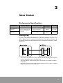
Performance Specification ......................................................................... 17
Description .................................................................................................. 17
Types of Slave Station................................................................................ 18
Slave Unit Dimensions ............................................................................... 19
Part Names and Functions ......................................................................... 20
Installing remote I/O Slave Unit ................................................................ 22
4. Transmission Time .................................................. 25
Transmission Time...................................................................................... 25
5. Interface of Remote I/O System .............................. 27
System Register Summary About Remote I/O System Control ............. 27
Interfacing Sequence of Remote I/O System ........................................... 29
Interfacing Pattern of Remote I/O System ................................................ 30
Sequence of Interface and Setting ............................................................ 32
6. Remote I/O Map ....................................................... 41
Configuration of Remote I/O Map ............................................................. 41
Present Value I/O Map and Registration
I/O Map ........................................................................................................ 44
Setting of Base Word No............................................................................ 47
3
7. Operation Mode Setting of Remote I/O System ...... 49
Description of the Operation Modes for Controlling the Remote
I/O System ................................................................................................... 49
Remote I/O Control When Error Occurs.................................................... 49
Slave Station Connecting Confirmation Mode......................................... 53
Remote I/O Update Timing Method .......................................................... 54
8.
Power Up Sequence ................................................ 55
Power Up sequence.................................................................................... 55
Reference Checking Flow chart ................................................................. 56
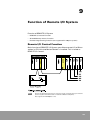
9. Function of Remote I/O System............................... 59
Remote I/O Control Function ..................................................................... 59
Shared Memory Access Function.............................................................. 60
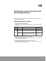
10. Finding the cause of an Error and Correcting the
Error ........................................................................ 69
Checking Sequence of Error ...................................................................... 69
Error Code of Remote I/O ........................................................................... 70
Checking of Slave Station that Error Occurs ............................................ 71
11. Troubleshooting ...................................................... 73
Troubleshooting Flow Chart ...................................................................... 74
Checking of LED Lighting Condition ......................................................... 86
4
1
Features and System
Configurations
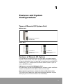
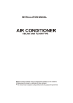
Types of Remote I/O System Unit
Master Unit
NX700 Remote I/O Master
(NX-MASTER)
Slave Unit
for NX700 PLC
for NX70 PLC
NX700 Remote I/O Master
(NX-MASTER)
NX70 Remote I/O Slave
(NX70-SLAVE)
Features of Remote I/O System
It is possible to send and receive I/O information to remote location
control system by two-wire cable, and possible to handle distributed
I/O device efficiently. Also, it is possible to install maximum 3 MASTER
stations per a PLC, and possible to connect SLAVE stations up to 32
with a MASTER station.
I/O Remote control with NX700plus PLC
I/O information can be exchanged between a Master station and Slave
station (included Slave link station) with two-wire cable.
High speed, long distance communication of I/O information
The system can support for a total communication distance of up to
200m per port at a communication rate of 500 Kbps.
5
I/O control up to 1024 points per Master station
A CPU Unit can control up to maximum 3 Master Units.
The Master Unit can accommodate up to 32 slave stations, or 1,024
points I/O.
Also, each Master Unit has two ports which can handle 2
communication paths, allowing a maximum of 4 communication paths
to be created.
Various type of Slave Units and I/O Units can be used.
On the slave station, you can install I/O Units for the NX70, NX700 PLC
by using the NX70, NX700 Slave Unit.
You can also use Slave link Units (8points type and 16points type and
32 points type) to increase the number of I/O points as necessary for
each slave station.
Maintain functions to errors such as a disconnection of
communication cable or encountering a problem
Control advanced Units on a Slave station (except Link)
In PLC system that is installed with Slave station, possible to use
advanced Units (SCU, HSC, A/D.....etc.) including general I/O Unit.
(except Multi Wire-Link, Master Unit)
6
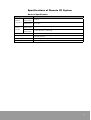
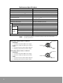
Specifications of Remote I/O System
General Specification
Item
Ambient
Temperature
Ambient
Humidity
Specification
Operating
Temperature
0 to 55 °C
Storage
Temperature
-25 to 70 °C
Operating
Temperature
5 to 95% RH (Non-condensing)
Storage
Temperature
5 to 95% RH (Non-condensing)
Vibration Resistance
10 to 55Hz/1 min., amplitude 0.75mm, each direction of X, Y, Z for 10 min.
Shock Resistance
Occasional excursions to 15g/11ms, half-sine in each of three mutually
perpendicular axes
Noise Resistance
Noise Voltage 1500Vp-p, Noise Pulse 50nS, 1 µs (Noise simulator)
Operating condition
No corrosive gas or severe dust conditions are allowed
7
Performance Specifications
Item
Specification
Communication Method
Two-wire, Half Duplex
Synchronous Method
Asynchronous System (Start to Stop Method)
Communication Distance per port (1)
200 m
Communication Speed
0.5 Mbps
Communication Path
2 conduct cable (VCTF Cable)
Twisted-Pair Cable (2)
Interface
RS-485
Transmission Error Check
CRC (Cyclic Redundancy Check)
Controllable Master Unit per CPU
Max. 3 Units
Interfacing Slave Unit per Master Unit
Max.32 Stations (Units)
I/O control
Control
I/O Point
Control
Slot No.
Per CPU Unit
Max. 1,024 points
Per Master Unit
Max. 1,024 points
Per CPU Unit
Max. 64 slots
Per Master Unit
Max. 64 slots
Per Slave Unit
Max. 25 slots (for NX700), Max. 8 slots (for NX70)
Unit that cannot be installed on Slave Unit System
NOTE
(1)
(2)
Master Unit, Optical Unit, MW-Link Unit
Transmission distance is changed according to usage cable and Unit type
Cable specifications
VCTF (Vinyl Cabtyre Cable): 2-conductor
Conductors
• Conductor
a. Size: Min. 0.75 mm2 (AWG 18 or larger)
b. Resistance: Max. 25.1Ω/km (at 2 °C/ 68°F)
• Cable
a. Insulation thickness: Min. 0.6mm (0.24in.)
b. Molding jacket diameter: 6.6mm (2.6in.)
Insulation
Molding
Jacket
VCTF (Vinyl Cabtyre Cable): 2-conductor
Conductors
• Conductor
a. Size: Min. 0.75 mm2 (AWG 18 or larger)
b. Resistance: Max. 25.1Ω/km (at 2°C/ 68°F)
• Cable
a. Insulation thickness: Min. 0.6mm (0.24in.)
b. Molding jacket diameter: 6.6mm (2.6in.)
8
Insulation
Jacket
Remote I/O System Configuration
Configurations
Master System
MASTER
MASTER
NX-MASTER
Max. 32
slave stations
can be connected
to one master.
Simple
wiring with
RS-485 twistedpair cable
SLAVE
SLAVE
NX70 Series
NX70 Series
Slave Unit
Slave Unit
SLAVE
NX700 Series
Slave Unit
Slave System
SLAVE
SMC Inc.
SLAVE
NX700 Series
Slave Unit
NX700 Series
Slave Unit
9
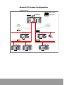
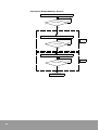
Basic System Configuration
10
•
REMOTE I/O System is a RS-485 mode (multi-drop) network that is made
up with Master System (CPU Unit + Master Unit), Slave System (Slave Unit
+ I/O Unit etc.), and transmission cable (two-wire cable) that is interfaced
to each stations. CPU Unit of Master System control I/O of Slave
System through Master Unit.
•
Master System is possible to interface by mixing various Slave Units, such
as Slave Unit of NX700 and NX70 PLC.
2
Master Station
Performance Specification
Product Type
for NX700 PLC
REMOTE I/O
Master Unit
Installation Method
Possible to use by installing at
basic and Expansion
backplane
NX700: up to 3
Current
Consumption
450mA (at 5V DC)
Product No.
NX-MASTER
Basic Configuration
•
The function of Master station is that transmits I/O information of CPU Unit
to Slave stations.
•
Configures Master System of REMOTE I/O System with CPU Unit.
Possible to install up to 3 Master station per a CPU Unit.
Possible to Install to Master backplane or Expansion backplane.
•
Master Unit is installed to I/O slot of
Basic backplane or Expansion
backplane.
•
It is called as a Master station1,
Master station2, Master station3 in
order of installing location.
•
Possible to install Master Unit on the
Expansion backplane.
•
Possible to configure two way
transmission lines because there are
two ports per a Master Unit
11
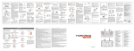
Part Names and Functions
NX700 PLC Master Unit (NX-MASTER)
171
25 9
24
8
1632
MASTER
NX-MASTER
COM ERR FLK TERM
c Station No. and
Operation Status Display
1 ~ 16
17 ~ 32
e Station No. Display
Selection switch
g RS-485 Interface
3
2
1
ON
f
ON
(Dip S/W)
(Front)
12
(Bottom)
The functions in each part
Station Number LEDs
Indicates the slave station number (01 to 32) of the slave station which
is connected to the Master Unit.
External Diagram and Functions (NX700 PLC Master Unit)
c Station No. Display and Operation
Status Display
17
25
24
1
8
9
16
MASTER
NX-MASTER
COM ERR FLK TERM
•
LEDs of Slave Units No. 1 to 32 which are connected to Master Unit.
•
Checking for lights by changing display range either 1 to 16 or 17 to
32 with display selection switch.
“COM”, “ERR” LED: Communication and operation status.
LED
Display
32
(On): Stand-by
COMM.
(Communica
tion Status)
Light on
(Fast flickering): Transmitting in normal operation
(Slow flickering): Transmitting in stop mode
(Off): Transmission error
Fast flickering (0.2sec interval)
(On): Unit malfunction
Slow flickering (1.0sec interval)
(Fast flickering): Slave Station No. Configuration error
ALARM
(Error)
Light off
: Restricted Unit mounting error
(Off): Normal
(On): Using Remote I/O
(On): End Station
(Off): Not an end station.
Dip Switch
Station (Slave) No. Set display range to either 1 to 16 or
17 to 32 with this switch.
1∼ 1 6
e Station (Slave) No. Display
Selection switch
17 ∼ 32
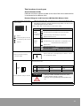
f Operation mode setting switch
Select mode setting when choosing transmission path, setting end station, or
communication error.
SW.
MODE
SW.
3
2
1
3
1, 2
Operation
OFF
ON
Communication
error mode
Operation stop
mode
Operation continue
mode
Select end station
Not an end terminal
An end station.
ON
Factory default setting is all OFF.
g RS-485 Interface
ATTENTION
• Settings of SW1 and SW2 must be the same.
• Factory default setting is all OFF.
• Settings are recognized only when power turns
on.
Connection terminal for network transmission cable. 1 port on the terminal.
13
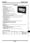
Master Unit Dimensions
NX700 Remote I/O Master Unit (NX-MASTER)
35.0mm
104mm
COM ERR FLK TERM
17 1
25
8 24
16
32
9
1
MASTER
NX-MASTER
6
17 32
115.5mm
+
FG
14
Installing a Master Station
A Master station can be configured with a Master Unit installed on the
Master backplane (With a CPU Unit and Power Unit) or an Expansion
backplane (with a Power Unit) One CPU can control a maximum of 3
Master Units.
Location of Master Station
The Master Unit can be installed in any I/O slot on a Master backplane
or Expansion backplane
•
NX700 Master Unit (NX-MASTER)
15
Installation of Master Station
•
Be sure to remove or install the Master Unit only when all power is OFF.
•
A maximum of 3 Master Units can be installed on PLC System.
•
Do not touch its connectors on rear side of the Unit or Backplane with your
hand. Static electricity build-up on your body can damage.
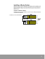
NX700 PLC Remote I/O Master Unit (NX-MASTER)
1. Fit the Unit tabs in to the Unit holes on the backplane.
2. Push the Unit in the direction of the arrow and mount on to the backplane.
3. After properly mounting the Unit to the backplane, secure the mounting screws at
the top.
16
3
Slave Station
Performance Specification
Product Type
Installation Method
NX700 REMOTE I/O
Slave Unit
Use by installing at CPU
Unit location of Master
backplane
NX70 REMOTE I/O
Slave Unit
Communication Port
RS-232/422 1 Port
It was not operated on
NX700plus CPU Unit
None
Current
Consumption
Product No.
400mA
NX-SLAVE
200mA
NX70-SLAVE
Description
I/O that is controlled from REMOTE I/O System to Master System (CPU
Unit + Master Unit) is called as Slave System. Possible to interface up
to maximum 32 Units per a Master Unit, and control maximum 1,024
points I/O.
•
Slave Unit is possible to mix. Slave Unit of NX700, NX70 System Slave link
Unit are possible to use as Slave System.
•
Set station No. to each Slave System. I/O Number is allocated in order of
station No.
Not necessary to set station No. in order of Master System. Also, no matter
even though there are no station No.
17
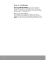
Types of Slave Station
Slave Unit (for NX700, NX70 PLC)
Install Slave Unit instead of CPU Unit at the CPU slot location of
Master backplane. (see the previous page picture). The system is
installed with Slave Unit as Slave Unit Section that is shown previous
page. Also, Slave System can control advanced Unit (SCU, Positioning
Unit, HSC, A/D,.......) including I/O Unit.
Slave Unit Correspondence Device
Devices that are used as Slave Unit by interfacing to company
concerned Master Unit with products of the third party. Possible to
interface with Solenoid Valve (Manifold Electronic edge) that is on sale
in SMC Company, CKD Company in Japan. (see their manual for more
detail)
18
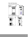
Slave Unit Dimensions
NX700 Remote I/O Slave Unit (NX-SLAVE)
35.0mm
104mm
COM
ALARM
SLAVE
NX-SLAVE
Stat
ion No.
NX70 Remote I/O Slave Unit (NX70-SLAVE)
35mm
88mm
SLAVE
NX70-SLAVE
COM
ALARM
Station No.
4
3
2
1
OFF
105mm
ON
19
Part Names and Functions
NX700 Remote I/O Slave Unit (NX-SLAVE)
COM
ALARM
SLAVE
NX-SLAVE
c Operation
Status Display
00
Station No.
0
4
3
2
1
0N
d Station No.
Setting switch
+
-
f RS-485 Interface
FG
(Bottom)
(Front)
e Operation Mode Switch
NX70 Remote I/O Slave Unit (NX70-SLAVE)
SLAVE
NX70-SLAVE
COM
ALARM
c Operation Status Display
00
Station No.
0
4
3
2
1
OFF ON
d Station No.
Setting switch
e Operation
Mode Switch
+
FG
(Front)
20
f RS-485 Interface
External Diagram and Functions (Slave Unit)
c Operation Status Display
COMM.
○
ALARM
○
Communication and operation status.
LED
Display
(On): Stand-by
COMM.
(Communica
tion Status)
Light on
(Fast flickering): Transmitting in normal operation
(Slow flickering): Transmitting in stop mode
Fast flickering (0.2sec interval)
(Off): Transmission error
Slow flickering (1.0sec interval)
Light off
(On): Unit malfunction
(Fast flickering): Slave Station No. Configuration error
ALARM
(Error)
: Restricted Unit mounting error
(Off): Normal
d Station No. Setting switch
(Rotary switch)
the tens
column
Setting station No. for Remote I/O System. (Turn the dial and align the
arrow () with the number you want. In addition, the numbers in tens
and ones columns should be set separately.)
the ones
column
ATTENTION
Station No.
e Operation Mode Setting Switch
M ODE
SW.
End station setting, mode setting for communication error
SW.
4
3
OFF
ON
RS422
RS232C
3
Output on
communication error
Output OFF
Output ON
1, 2*
End station setting
Not an end terminal.
An end station.
ATTENTION
f RS-485 Interface
OFF
4*
ON
Factory default setting is all OFF.
Operation
RS422/RS232C
Selection Switch
2
1
• When No. outside the range is set, setting error
(ALARM LED flickering) occurs and transmission
fails.
• Refer to Step e of Remote I/O connection.
• Settings are recognized on power input.
• Settings of SW1 and SW2 must be the same.
• Settings are recognized only when power turns
on.
• SW4 is communication connector for
programming tools. (Only for NX700)
(But SW4 is not used on NX700, NX70, Slave
Units.)
Connection terminal for network transmission cable.
21
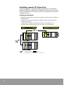
Installing remote I/O Slave Unit
There are NX700 PLC Type (NX-SLAVE), and NX70 PLC Type (NX70SLAVE) in REMOTE I/O Slave Unit. REMOTE I/O Slave Unit is installed
at CPU Unit location of PLC System, and it is controlled as a Slave Unit
of Master System
Installation Condition
•
REMOTE I/O Slave Unit have to be installed at CPU Unit location of Master
backplane Unit.
•
Install I/O Unit or Advanced Unit. (but, MW-Link Unit and Interrupt Unit
cannot be installed)
•
Configuration condition (Limitation of current consumption, etc.) is
common. Use expansion cable (1.2m or 3m) in case of expansion.
NOTE
Install CPU SLOT of
part.
Install I/O Unit or advanced Unit to each I/O Slot.
22
Installation Method
•
Install and remove when power is OFF
•
Possible to use by installing up to total 3.
•
Don't touch connector terminal part. it causes faulty contact or faulty
operation by static electricity.
NX700 PLC Remote I/O Master Unit (NX-SLAVE)
1. Attach projecting part (2 parts) of Unit to the Unit fixing hole of Master
backplane.
2. Install Unit at the Master backplane by pressing in the direction of arrow.
3. Fix it with screw after installing at the Master backplane.
23
24
4
Transmission Time
Transmission Time
Indicates transmission time that is required to control Remote I/O
System.
Remote I/O Scan Time (TR)
REMOTE I/O Scan Time is a time to set every input DATA that is
received from each Slave Unit to buffer which is inside of Unit, since
every output DATA that is set buffer in the Unit is sent to each Slave
Unit which is interfaced with Master Unit.
TR = 0.8 + (0.85x n) + (0.55 x N) + (0.13 x W) (ms)
n = Slave link No.
N= Slave Unit No.
W= Remote I/O usage I/O Word No.
EXAMPLE
In case of interfacing,
10 Slave Unit (Input 16 points, Output 16 points),
1 Slave Unit (4 Input 32 points Unit, 4 Output 32 points Unit)
TR = 0.8 + (0.85x 10) + (0.55 x 1) +0.13 x
(32 x 10) + (32 x 4) + (32 x 4)
16
= 14.53 ms
Remote I/O Memory Access Time (TRM)
Remote I/O Memory Access Time is a time to receive MEMORY
ACCESS COMPLETION MESSAGE from Slave Unit since Master Unit
takes MEMORY ACCESS REQUEST from CPU Unit.
TRM = TR x 2 + (0.7 + 0.17 x WRM) (ms)
TR = Remote I/O Scan Time
WRM = Memory Access Word No.
EXAMPLE
In case of interfacing,
10 Slave Unit (Input 16 points, Output 16 points),
1 Slave Unit (4 Input 32 points Unit, 4 Output 32 points Unit)
(32 x 5) + (32 x 2) + (32 x 2) + 32
TRM = 0.8 + (0.85x 5) + (0.55 x 1) + 0.13 x
16
x 2 + (0.7 + 0.17 x 32)
= 22.54 ms
25
Remote I/O Delay Time (TRES)
REMOTE I/O Delay Time is a time to output signal based on the result
of operation computing since input signal that is inputted to Slave Unit
is carried to CPU Unit with Master Unit.
TRES = TIRES + TC + TORES
TRES : REMOTE I/O Delay Time
TIRES : REMOTE I/O Input Delay Time
TORES : REMOTE I/O Output Delay Time
TC: CPU Unit SCAN TIME
Maximum value of REMOTE I/O Delay time is shown below.
TRES.MAX = TIRES.MAX + TC + TORES.MAX
TIRES.MAX = TIDLY + TR + Ta
TORES.MAX = TR x 2 + TODLY
TIDLY : Input delay time
TR : Scan time of the remote I/O System
TA : When synchronous mode
• When TC < TR , Ta = TR
•
When TC > TR , Ta = TC
When synchronous mode
• When TC < TR , Ta = TC + TR
•
26
When TC > TR , Ta = TC
5
Interface of Remote I/O System
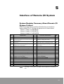
System Register Summary About Remote I/O
System Control
REMOTE I/O Map Setting and Base Word Setting are needed to
operate REMOTE I/O. The flags for operation are shown below.
Master 1 (Loop 1): F8 REGISTER
Master 2 (Loop 2): F9 REGISTER
Master 3 (Loop 3): F10 REGISTER
Flag
Initial
Explanation
Value
Set Value and Contents
I/O
F8.0
Yes/No of Master Unit installation
1
1: Unit is installed
Output
F8.1
Request REMOTE MAP resetting using real
slot information (1)
0
1: Request setting (Real value)
Input
F8.2
Starting operation after checking Slave Unit
that is set (1)
0
1: Operation after checking Slave Unit
Input
F8.3
Request REMOTE MAP resetting using user
configured slot information (1)
0
1: Request setting (user configured
slot info.)
Input
F8.4
Request real slot information READ (1)
0
1: Check interface.
Input
F8.5
Display REMOTE Base Word setting
1: Already configured
Output
F8.6
Ignore in case of REMOTE Error
0
1: Ignore ERROR
input
F8.7
Request REMOTE Master RESET
0
1: Request RESET
input
F8.8
Indicate error in case of initializing REMOTE
0
1: Initializing ERROR
Output
F8.9
Indicate AC Fail error in Slave Unit
0
1: AC Fail
Output
F8.10
Indicate I/O Unit change in Slave Unit
0
1: Unit change
Output
F8.11
Indicate error in Slave Unit
0
1: Slave Unit ERROR
Output
F8.12
Indicate error on communication
0
1: Communication ERROR
Output
F8.13
Not used
F8.14
Indicate executing RMRD,RMWR order
0
0: Complete execution
Output
F8.15
Indicate Failure of RMRD,RMWR order
0
0: Normal completion
Output
F12.1
Indicate REMOTE MAP configured or not
0
1: Configured
Output
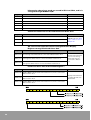
NOTE
The flags
Unit
(1)
correspond to F8 register, and are applied to every Master
27
Information about base word are stored in SR11 to SR16, and it is
changed through WINGPC S/W.
Register
Contents
Initial Value
SR11
Base word of REMOTE Master Unit 1 (Loop 1)
64
SR12
Base word of REMOTE Master Unit 2 (Loop 2)
96
SR13
Base word of REMOTE Master Unit 3 (Loop 3)
112
SR14
COMPLEMENT Value of Base word of REMOTE Master Unit 1 (Loop 1)
-
SR15
COMPLEMENT Value of Base word of REMOTE Master Unit 2 (Loop 2)
-
SR16
COMPLEMENT Value of Base word of REMOTE Master Unit 3 (Loop 3)
-
Communication Error Code with Interfaced Slave Unit
Register
Contents
SR261
Master Unit 1 transmission line ERROR
SR262
Master Unit 2 transmission line ERROR
SR263
Master Unit 3 transmission line ERROR
Remarks
ERROR Code See "Error
Code of Remote I/O" in
Chapter 10
AC Fail or Error Operation Slave Unit Information Display
Register among Interfaced Slave Unit (1)
Register
SR274, 275
Contents
SR274='0002H' indicates that error occurs on Slave Station
No.2 among Slave Units that are connected to Master Station No.1.
SR276, 277
SR276='0003H' indicates that error occurs on Slave Station No.1 and
2 among Slave Units that are connected to Master Station No.2.
SR278, 279
SR279='0004H' indicates that error occurs on Slave Station No.19
among Slave Units that are connected to Master Station No.3.
Interfaced Slave Unit Information Register
Register
28
Remarks
Display Slave Unit that
error occurs among
Slave Units that are
connected to Master
Unit
(1)
Contents
SR264, 265
SR265='0003H' indicates that Slave Station No.17, 18 are connected to
Master Station No.1.
SR266, 267
SR266='0003H' indicates that Slave Station No.1, 2 are connected to
Master Station No.2.
SR268, 269
SR269='0003H' indicates that Slave Station No.17, 18 are connected to
Master Station No. 3.
Remarks
Display Slave Unit that
is interfaced with each
Master Unit.
Interfacing Sequence of Remote I/O System
This chapter explains about interfacing and setting method when
REMOTE I/O System is constructed. Interface and setting are executed
by interfacing pattern or operation content. Precautions are shown
below.
•
Interfacing pattern (See next page), Station No. of Slave Unit.
•
Remote I/O Map (See "Chapter 6")
•
Handling in case of error (See "Remote I/O Control When Error Occurs" in
Chapter 7)
•
Timing of Remote I/O Refresh "Remote I/O Update Timing Method" in
Chapter 7)
Summary of Interface and Setting Sequence
See "Sequence of Interface and Setting" in Chapter 5 for more detail.
POWER OFF of Each Device.
Install Master Unit, Slave Unit,
exclusive construct system per each
Unit.
Execute I/O allocation, change of operation
mode or registration.
• Remote I/O Map
• Selecting RUN mode in case of error
Wiring Transmission Cable.
Execute setting of each Unit by
interfacing pattern.
• Setting usage transmission line
• Unit No. of Slave Unit.
• If it is Termination Unit or not
• Operation in case of error (1)
Check out that CPU Unit is on PROG.
mode, and supply power.
• Timing change of I/O Refresh
Operate with initial value of factory
shipping in case that registration or setting
change are not executed.
• Remote I/O Map
-> Base Word No.
-> Present Value Mode
• In case of error
-> CPU Unit Stop
• Remote I/O Refresh
-> Ordinary I/O Refresh
Interface and Setting Completion
NOTE
Operation Mode is set with each Unit and CPU Unit separately.
See "Remote I/O Control When Error Occurs" in Chapter 7 for more detail
about setting, operation condition, and so on.
29
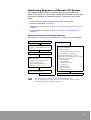
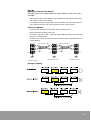
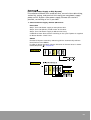
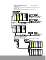
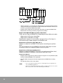
Interfacing Pattern of Remote I/O System
There are 6 interface methods of Master Unit and Slave Unit. 6 types
(A to F) of interface method are shown below.
NOTE
•
Don't execute other interface except 6 types that are shown below.
•
Execute interface of transmission CABLE in order of Master Unit.
•
Don't execute multiple wiring.
•
See "Sequence of Interface and Setting" in Chapter 5 for more detail
about interface and setting.
Master Unit
Interfacing
Pattern A
Slave Unit
○ : Interfacing Mode
● : Interfacing Mode (In case of terminal Unit)
1 transmission line (use only port I) .
Terminal Unit is a Slave Unit of Master Unit (port I) and termination.
Impossible to interface by using only port II.
Master Unit
Port I
Slave Unit (Total 32 Units)
Interfacing
Pattern B
1 transmission lines (use only port I) .
Terminal Unit is a Slave Unit of both terminal of each line. Impossible to use
by using only port II.
Master Unit
Port I
Port I
Slave Unit (Total 32 Units)
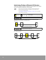
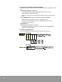
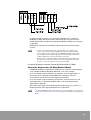
30
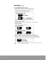
Interfacing
Pattern C
1 transmission line (use only port I, II) 1 Loop
Terminal Unit are Master Unit (PORT I,II common) and Slave Unit (PORT I and
PORT II).
Master Unit
Port I
Connection
Pattern D
2 transmission lines (use port I, II) . 2 Loop
Terminal Unit is a Slave Unit of both terminal of each transmission line.
Master Unit
Port I
Connection
Pattern E
Port I
2 transmission lines (use port I, II) • I is 1 LoopII is 2 Loop
In Terminal Unit, transmission line using port I are Slave Unit of Master Unit
and terminal, and transmission line using port II is a Slave Unit of both
terminal.
Master Unit
Port I
31
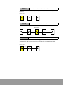
Sequence of Interface and Setting
Explain sequence of interface and setting when REMOTE I/O System is
constructed.
Preparation
•
POWER OFF of each device.
•
Preparation and installation of each device of Master Unit and Slave Unit.
• Install each Unit to designated location. The system that executes
Remote I/O control of I/O 128 points, is constructed with a Master
Unit by interfacing 3 Slave Units like above picture. Therefore, the
CPU Unit executes control of total I/O 176 points (including ordinary
I/O area (32 points) and Remote I/O area (128 points).
32
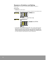
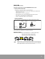
Step c
[Wiring of Transmission Cable]
Wiring transmission cable (two-wire cable) between each Unit that is
installed.
•
Twisted pair cable or UL Style No. 2919 24AWG of LG (korea) equivalents
are used as transmission cable.
•
The length of transmission cable is less than Max. transmission distance
per eachtransmission line (from terminal Unit to terminal Unit).
Interfacing Method
•
Interface and wiring are executed in order of Master Unit
•
Wiring interface through each Unit.
•
Interface + side and + side, - side and - side of RS-485 Interface of each Unit
(picture is shown below)
•
Interface one side of shield wire of transmission cable, and fold (picture is
shown below)
+
Transmission cable
+
Transmission cable
+
-
Shield
F.G
[RS-485 Interface]
Shield
F.G
[RS-485 Interface]
F.G
[RS-485 Interface]
Example of Wiring
33
Sequence d
[Setting of Master Unit]
Set about REMOTE I/O Master Unit
1. Selection of transmission port (transmission line).
Select and set transmission port that will be used.
Set SW1, SW2 of Mode Selector Switch.
2. Setting of Terminal Unit.
Set Terminal Unit in case of interfacing with 1 transmission line.
Interfacing Method
Set SW3, SW4 of Mode Selector Switch.
3. Mode Selector Switch In Case of Error on Communication.
When error occurs on communication, choose if Remote I/O System
control is stopped or not. Configure SW7 of Mode Selector Switch.
NOTE
34
ERROR LED of CPU Unit is lighting when error occurs on setting of terminal Unit.
Supply power again after setting.
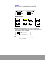
Sequence d
[Setting of Slave Unit]
Set about system that is installed REMOTE I/O Slave Unit.
1. Setting of Slave Station No.
Attention in case that Unit No. is set on Slave Unit.
•
Possible to interface up to 32 stations per a Master Unit. (Station No.
Setting Range: 01 to 32)
•
Total I/O point is less than 1,024 points.
•
Set station No. that is not overlapped with other Slave station.
•
Unit which is interfaced with same Master Unit.
•
I/O No. is allocated in order of small station No.
Interfacing Method
Set station No. by turning Station No. selector switch (rotary switch).
the tens
column
Station No.
Station No.
Setting switch
the ones
column
Use screw driver or
other tools to turn.
●
3
Example setting “3”
No matter even though there is no station No.
Don't need to set station No. in order of interface.
Example of setting
Slave Unit (I) that comes out to Sequence c is Slave station No.1
Slave Unit (II) is Slave station No.3
Slave Unit (III) is Slave station No.4
NOTE
Allocated I/O No. in order of Slave Unit (I), Slave Unit (II), and Slave Unit (III) See
Sequence f about I/O No. allocation. Don't turn Station No. selector switch after
power supply. No matter on operation because it is controlled by I/O Map for
power supply. However, it causes errors for next operation.
35
2. Setting of Terminal Unit (Station) See "Power Up sequence" in
Chapter 8
Set Terminal Unit in case of interfacing to transmission line
Setting Method
Set SW1, SW2 of Mode Selector Switch.
Example of Setting
3. Setting of Output Maintain/Stop in Case of Error on Communication
In case of error on communication, choose [Stop or Maintain in setting of
output. Set Mode selector switch SW3.
NOTE
36
•
When error occurs on terminal Unit setting, ERROR LED of CPU Unit is blinking in case of power supply. Supply power again after resetting.
•
Slave Unit that doesn't have terminal Unit, is OFF setting on SW1 and SW2
of Mode selector switch.
Sequence f
[Turns ON Power Supply to PLC System]
If installation of Master Unit and Slave Unit, transmission cable wiring,
station No. setting, and terminal Unit setting are completed, supply
power to PLC System. After power supply, Remote I/O control is
possible, so checking of run is possible.
1. Check of Power Supply, Remote I/O Control
Procedure
Step1. Turns ON Power supply to every Slave Unit.
Step2. Turns ON [PROG.] mode switch of CPU Unit.
Step3. Turns ON Power supply to Master Unit lastly.
COM.LED of each Slave station is blinking in fast cycle if power is supplied
to Master Station. Check it out.
Check
Remote I/O System control by allocating I/O No. automatically to Slave
Unit (Present Value Mode).
In order of above sequence, I/O No. allocation in Present Value is shown
below (Sequence c). "Chapter 9".
37
2. Registration and Setting of Remote I/O Map
Possible to register allocation of I/O Number of Remote I/O System to CPU
Unit.
Once Remote I/O Map is registered,
•
Even though power supply is delayed to Slave Unit, it can be
controlled with registered I/O No.
•
Program execution can be waited until power supply to every Slave
Unit
Also, If WINGPC S/W is used, it is possible to allocate randomly.
•
Need to prepare I/O point in case of adding Slave Unit.
•
If there is many Remote I/O points, usage memory area can be
extended with Remote I/O.
Setting Method
Register by using programming Tool.
•
Use WINGPC S/W (Use computer): Register by selecting REMOTE
CONFIG In SYSTEM Menu
3. Example of I/O Allocation.
In case of adding (Use I/O 80 points) by random I/O allocation.
38
4. Setting of CPU Unit
Possible to set operation content of Remote I/O control with System
Register Setting of CPU Unit. Possible to control in user program.
System Register Item that is related to operation mode of Remote I/O
System.
Flag
Contents
Initial value
F8.2
Operation after checking Slave Unit that is set.
0: Operation that is not
checked
F8.6
CPU Unit operation continuation/ stop in
case of error on communication.
1: Ignore ERROR
Example. Setting by Ladder program
39
40
6
Remote I/O Map
Inputs/ Outputs of the REMOTE I/O System slave station are controlled
with I/O numbers, as well as with Inputs/Outputs to an in ordinary
system. The I/O Number allocation of REMOTE I/O System is called as
Remote I/O Map.
Configuration of Remote I/O Map
I/O Allocation of Slave station is shown below.
•
Allocate head word No. that is set to each REMOTE I/O Master Unit. Head
Word No. is called as Base Word No. (Configuration of word Unit).
Possible to install up to 3 Master Units per a CPU Unit. Called as Master
Unit 1 (Loop1) Master Unit 2 (Loop2),and Master Unit 3 (Loop3) in order of
CPU Unit.
•
I/O No. is allocated to each Unit in order of small Unit No. Don't need to set
Unit No. in order of interfaced sequence. (I/O No. is allocated in order of
Unit No. Not interfaced sequence.)
There are 3 types of Remote I/O Map Registration Mode.
•
Auto Mode: mapped automatically with Present I/O Map
•
Manual Mode1: mapped manually with Present I/O Map by user
•
Manual Mode2: mapped manually with Random I/O Map by user
Memory Allocation
Ordinary I/O area R0.0 to 63.15
(possible to control 1,024 points)
Master Unit 1 Loop R64.0 to R95.15
(possible to control 512 points)
Master Unit 2 Loop R96.0 to R111.15
(possible to control 256 points)
Master Unit 3 Loop R112.0 to R127.15
(possible to control 256 points)
NOTE
In case of many REMOTE I/O points, possible to increase usage area of Loop that
needs many I/O No., and decrease different Loop area by using WINGPC S/W.
41
Information flag about REMOTE I/O Map Setting and Base Word
REMOTE I/O Map Setting Requesting Flag
REMOTE I/O Map Setting Requesting Flag
Flag
Contents
Initial Value
Remarks
User can control directly.
WINGPC S/W controls
automatically in case of using GPC
S/W.
F8.1
REMOTE I/O Map resetting request
using actual value.
0
F8.3
Setting request using user define MAP
0
REMOTE I/O Base Word Setting Information
Flag
Contents
Already setting
Remarks
F8.5
Y/N of Master Unit 1(Loop 1) Base word
1
Output
F9.5
Y/N of Master Unit 2(Loop 2) Base word
1
Output
F10.5
Y/N of Master Unit 3(Loop 3) Base word
1
Output
REMOTE I/O Map Registration Information
F12.1
Y/N of REMOTE I/O Map Setting
Register
1
Content
Output
(1)
Initial Value
SR11
Base Word of REMOTE Master Unit 1(Loop 1)
64
SR12
Base Word of REMOTE Master Unit 2(Loop 2)
96
SR13
Base Word of REMOTE Master Unit 3(Loop 3)
112
SR14
COMPLEMENT Value of Base Word of REMOTE Master Unit 1(Loop 1)
-
SR15
COMPLEMENT Value of Base Word of REMOTE Master Unit 2(Loop 2)
-
SR16
COMPLEMENT Value of Base Word of REMOTE Master Unit 3(Loop 3)
-
Precaution for I/O No. Allocation of Each Slave Unit
•
Beginning I/O No. of Unit is a next of ending I/O No.
•
Ending I/O No. of Unit is in accordance with occupied I/O point
•
Unit that has smallest Unit No. is beginning No. of Base Word No.
•
I/O No. is allocated in accordance with installed I/O Unit and occupied I/O
point of high functional Unit like ordinary system. I/O No. is allocated in
order of Slave Unit.
NOTE
42
(1)
Y/N of REMOTE I/O Map Setting is not marked in each Master Unit. If one of
installed Master Units is set, it is marked.
Example of I/O Allocation (I)
(N700 PLC SYSTEM)
Reference Item
Possible to change I/O allocation of Slave Unit System by using
WINGPC S/W.
Master Unit and Slave Unit don't have occupied point.
0
1
2
3
Example of I/O Allocation (II)
Below is an example of Loop.
Shows Remote I/O allocation of interfacing condition in 1 Loop.
43
Present Value I/O Map and Registration
I/O Map
REMOTE I/O Map is an allocation of Slave Unit I/O No. that is accepted
in CPU Unit in case of system operation. After that, execute REMOTE
I/O control in accordance with I/O Map.
Control by present value I/O Map
Operation with I/O Map that is allocated automatically to operating
Slave Unit in when On power to CPU Unit of Master Unit.
Control by registration I/O Map
Operation with registered I/O Map in CPU Unit of Master Unit.
Below are 3 types of Remote I/O Map Registration.
•
Auto Mode: mapped automatically with Present I/O Map
•
Manual Mode1: mapped manually with Present I/O Map by user
•
Manual Mode2: mapped manually with Random I/O Map by user
Recommend to use Manual Mode1 in case of operation.
Control by Present Value I/O Map [Auto Mode]
•
In case that REMOTE I/O Map is not registered to CPU Unit, I/O control is
executed in accordance with I/O Map that is configured automatically in
Slave Unit which power is already supplied. Base Word No. used basic
configuration in case that it is not configured.
•
In present value Map, CPU is operated based on I/O Map of Slave Unit
when power turns ON.
Precaution:
In case of factory shipping of CPU Unit, REMOTE I/O Map is not
registered.
Use Programming Tool (GPC, WinGPC) for REMOTE I/O Map and initial
setting of System register.
REMOTE I/O Map and initial setting of base word are used by WINGPC
S/W. (supported later)
44
•
In above example, power is not supplied of Station No.2. Configure
REMOTE I/O Map with Station No.1 and Station No.3 in present value
mode. Station No.2 cannot be accepted to REMOTE I/O Map even though it
is operated
•
REMOTE I/O Control is executed by interfacing partly on constructing
system.
NOTE
•
In case of executing Auto mode, supply power to Slave Unit of I/O
control before power supply to Master Unit System. Slave Unit that
power supply is late is not accepted to REMOTE I/O Map even though
it is operated. Allocated with high I/O point. I/O Number of Slave Unit
is different with the case that Slave Unit is operated.
•
When power is supplied to Master Unit System, if terminal Unit is not
interfaced, it causes (Disconnection or Power Supply Delay) Termination Error. In this case, disconnect and operate again.
In case of operation, execute Control by Registration I/O Map.
Control by Registration I/O Map [Manual Mode]
•
If REMOTE I/O Map is registered to CPU Unit, I/O Control is executed with
same I/O Map by BACK-Up.(Base Word No. uses basic setting)
•
In case of power supply to Master Unit System, even though there is a
Slave Unit that is not operated (POWER OFF Condition), I/O No. is
connected to next Slave Unit with registered condition.
•
In case of power supply to Master Unit System, if Slave Unit that is not
operated before, is operated (POWER ON), it can be controlled with
registered I/O Number.
•
Slave Unit Interfacing Check Mode (System Register F8.2 is set with “1”)
Begin operation after registered Slave Unit is operated (1).
NOTE
(1)
In User LADDER program, F8.2 SET in case of first SCAN. See "Checking of
Slave Station that Error Occurs" in Chapter 10 about Slave Unit Interfacing Check
Mode.
45
•
Above example is an example that Station No.2 is not operated (No power
supply, No interface.) I/O Number is registered to Slave Station of No.2, I/O
control is possible by REMOTE I/O Map.
•
Register with Programming Tool (GPC, WinGPC) to register REMOTE I/O
Map before executing Control by registration I/O Map.
Registration Method (Manual mode allocation)
There are two Types of REMOTE I/O Map Registration (Manual mode),
- Registration of Present Value Map
- Registration of Random I/O Map
Registrations request is executed by setting('1) F8.1 or F8.3 flag it is
executed through Ladder program or WINGPC S/W.
Registration of Present Value Map (F8.1)
Register installed I/O to REMOTE I/O System (including every Slave
Unit).
Turn on the power of every REMOTE I/O System. Back-Up in case of
installing system or changing module (Unit) of system.
Registration of Random I/O Map (F8.3)
Register I/O Map to REMOTE I/O System (including every Slave Unit)
without installed I/O condition, and control with the I/O No.
Registration Method
•
Register with Programming Tool (Possible to register in only WinGPC S/W)
Handy-Loader(PGM500): not supported.
•
WinGPC S/W (Computer): Execute registration on REMOTE I/O Config
item.
See WinGPC Manual for more detail.
NOTE
46
•
It is not operated normally if there is something wrong on registration in
case of I/O Map Registration.
•
If there is no registered Slave Unit, standby condition that there is no Slave
Unit of Station No. (Slave Unit Interfacing Check Mode)
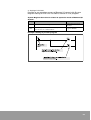
Setting of Base Word No.
Possible to register REMOTE I/O Base Word No. by random setting per
Master Unit. Possible to secure I/O point that is needed to each Loop.
Possible to use by controlling usage range of Remote I/O and Master I/
O range.
Setting
Range
Setting
Condition
0 to 127 word Unit setting for each Master Unit.
(ex.) If Base word of Master 3 is changed from 112 to 104, contact point
control of R104.0 R127.15 is possible in Master3 Loop.
Final I/O No. of ordinary I/O area < Base Word No. of Master 1
Base Word No. of Master 1 < Base Word No. of Master 2
Base Word No. of Master 2 < Base Word No. of Master 3
Condition 1
Set Base Word No. in order of CPU of Master Unit Installation location.
Any Base Word No. cannot be set less than Base Word No. of Master
Unit that is installed to near location of CPU Unit.
Base Word No.0
Ordinary I/O p
Possible to change
Master 1 Loop
Possible to change
Master 2 Loop
Possible to change
Master 3 Loop
Memory Area
Cannot be overlapped.
Precaution:
Register again in case of changing module in system in this case.
If it is not registered, it causes I/O Verify Error.
Condition 2
If Base Word No. of Master 1 is set as “0”, all of memory area are
Remote I/O. In this case, I/O Unit or high functional Unit cannot be
used in Master Unit System.
47
48
7
Operation Mode Setting of
Remote I/O System
Description of the Operation Modes for
Controlling the Remote I/O System
The operation modes for controlling the Remote I/O System can be
changed by setting the system Flags of the CPU
•
Remote I/O Control in case of Error. [F8.6 Flag]
The operation mode when a slave station does not work correctly can be
set to continue or halt the operation.
•
Slave Unit Interfacing Check Mode. [F8.2 Flag]
When a remote I/O Map is registered, you can start remote I/O control only
after all of the slave stations which have been registered in the CPU are
turned ON.
How to change the Remote I/O Operation Mode:
By setting the system flags of the CPU, you can change the remote I/O
operation mode. To set the system flags, use a Ladder program
Remote I/O Control When Error Occurs
Two types of error may occur in the Remote I/O system
•
Communication Error:
In case that Master Unit and Slave Unit cannot communicate each other
by power OFF or disconnection of transmission cable, check
•
Error of I/O or Intelligent Unit in the Slave station:
In a slave station where a Slave Unit is installed, an Input/ Output Unit or
Intelligent Unit has produced an error. This may occur because of a blown
fuse, a Unit hangs or a system error occurred
Setting Contents
Description
CPU Unit
System Flag F8.6 (Master Unit 1)
F9.6 (Master Unit 2)
F10.6 (Master Unit 3)
Operation in case of error on
communication
Master Unit
Registration Mode Selector Switch SW7
Remote I/O control in case of
error on communication
Slave Unit
Registration Mode Selector Switch SW3
Power ON/OFF in case of error on
communication
49
Operation when Error occurs on Communication
•
Communication Error occurs in case that Master Unit and Slave Unit
cannot communicate each other by disconnecting of transmission cable or
power of Slave station is off.
•
When error occurs, REMOTE I/O Communication Error is checked. Slave
station that cannot be communicated, can be checked with special Data
Register SR264 to SR269
Operation of Normal Slave Station
Possible to select 4 types of operation about normal Slave Station in
case of Communication error
Types of Operation
Mode
System
Register
Master
Mind
Operation in Case of
Communication Error
REMOTE I/O of Slave
Station
Return Method
F8.6
SW7
Normal
I/O
Stop I/O Operation (1)
0
OFF
Stop
operation
X (COMM: not changed)
Operate Master Unit
again
Stop I/O Operation (2)
0
ON
Stop
operation
X (COMM: not changed)
Operate Master Unit
again
Stop REMOTE I/O
Operation
1
OFF
Operation
○ (COMM: change)
Operate Master Unit
again
Continue I/O
Operation
1
ON
Operation
○ (COMM: change)
Automatic return (*)
1: Continue operation, X: Stop operation
NOTE
1.
(*)
If communication error is fixed (interfacing cable, power supply) about Slave
Station that cannot be communicated, execute control.
2. In case of Communication Error, power of Slave Unit is OFF in stop setting of Remote I/O control. No matter about the condition of Mode Selector Switch No.7 of
Slave Station. (Output continue mode/ Output stop mode)
50
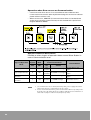
There are 4 types of Communication Error in case of normal Slave
Station operation.
1. Stop I/O Operation [1]
•
System Flag F8.6 of CPU Unit: 0 (Halt Operation)
•
Mode Selector Switch No.7 of Master Station: OFF
[Operation]: Stop every I/O operation. Communication error occurs
because COMM.LED (COM.LED) is blinking (1 sec. cycle) slowly in
normal Master and Slave Station.
[Steps to take]: Supply power again after fixing error. (disconnection of
transmission cable, etc.)
2. Stop I/O Operation [2]
•
System Flag F8.6 of CPU Unit: 0 (Halt Operation)
•
Mode Selector Switch No.7 of Master Station: ON (Continue Operation)
[Operation]: Stop every I/O operation. COMM.LED (COM.LED) is same
with normal condition in normal Master and Slave Station (0.2 sec.
cycle blinking)
[Steps to take]: Initialize Master Station with RUN Mode after fixing
error (disconnection of transmission cable, etc.)
3. Stop Only Remote I/O Operation
•
System Flag F8.6 of CPU Unit: 1 (Continue Operation)
•
Mode Selector Switch No.7 of Master Station: OFF (Halt Operation)
[Operation]: Stop only Remote I/O Operation. Continue operation about
I/O of Master Station System. Communication error occurs because
COMM.LED (COM.LED)°¼is blinking (1 sec. cycle) slowly in normal
Master and Slave)
[Steps to take]: Supply power again after fixing error. (disconnection of
transmission cable, etc.)
4. Continue I/O Operation
•
System Flag F8.6 of CPU Unit: 1 (Continue Operation)
•
Mode Selector Switch No.7 of Master Station: ON (Continue Operation)
[Operation]: Continue operation for I/O of normal Master Station and
Slave Station COMM.LED (COM.LED) is same with normal condition in
normal Master and Slave Station (0.2 sec. cycle blinking)
[Steps to take]: Slave Station that cannot be communicated is returned
automatically after fixing error (disconnection of transmission cable,
etc.). Lights-out by using initialize switch of CPU Unit in RUN Mode
because ERROR LED of CPU Unit is lighting.
Output condition of Slave Station that cannot be communicated.
Possible to keep output condition of Slave Station that cannot be
communicated with Master Station. Turn on Mode Selector Switch of
Slave Station. If output is ON, continue POWER ON. Not related to
setting of CPU Unit (System Flag F8.6, Mode Selector Switch No.7).
51
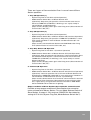
Operation in case that error occurs in Unit that is
connected with slave station.
In case that Input/ Output or Intelligent Unit that is interfaced to system
installing Slave Station have errors of fuse disconnection (TR, SSR
Output Unit) or scan error, possible to decide to stop or continue I/O
operation. If error occurs, Unit Error of Remote I/O (Error Code F8.11
(In case of Master station 1) is checked. Slave Station System that is
interfaced with faulty operation is checked with special data register
SR294 to SR299.
Faulty operation occurs on output Unit that is installed to slot 1 of
Slave station No. 1. If operation is continued, possible to control I/O
about Slave. No.2, No.3, and other Unit of Slave Station No.1. In case
that error occurs in the Unit of Slave station.
Operation of communication error in each setting
1. Stop I/O Operation
System Flag F8.6 of CPU Unit: 0 (Operation halt Mode)
No matter where setting of System Flag and Mode Selector Switch No.7
are.
[Operation]: Stop every I/O operation. COMM.LED (COM.LED) is same with
normal condition in normal Slave Unit that is interfaced (0.2 sec. cycle
blinking). POWER OFF.
[Steps to take]: Supply power of Master System again after changing
faulty Unit to normal Unit.
2. Continue I/O Operation [1]
System Flag F8.6 of CPU Unit: 1 (Operation Continue Mode). Mode
Selector Switch No.7 of Master Station: OFF (Operation Stop Mode)
No matter where System Flag F8.6 is. No matter that Mode Selector
Switch is on in case that F8.6 is “0”.
[Operation]: Continue operation of Remote I/O and I/O operation of Master
Station System. I/O operation of I/O Unit and high functional Unit is
executed normally about Slave Station System that faulty Unit is occurred.
[Steps to take]: Supply power of CPU Unit again after changing faulty Unit
to normal Unit.
52
3. Continue I/O Operation [2] (Automatic Return)
System Flag F8.6 of CPU Unit: 1 (Operation Continue Mode)
Mode Selector Switch No.7 of Master Station: ON (Operation Continue
Mode)
[Operation]: Continue Remote I/O and I/O Operation of Master Station
System. I/O operation of I/O Unit and high functional Unit is executed
normally about Slave Station System that faulty Unit is occurred.
[Steps to take]: Return automatically if power is supplied to Slave Station
System that the Unit is interfaced after changing faulty Unit to normal
Unit. Lights-out by using initialize switch of CPU Unit in RUN Mode
because ERROR LED of CPU Unit is lighting.
Slave Station Connecting Confirmation Mode
Begin operation by waiting power supply to every Slave Station that is
registered to REMOTE I/O Map if Slave Station connecting
confirmation Mode is set in case of operating REMOTE I/O System (In
case of turns On power to Master Station System).
•
Setting is executed with setting of System Flag F82. (Set with LADDER
program.)
•
Need Slave Station connecting confirmation Mode that REMOTE I/O Map
is registered. In case that REMOTE I/O Map is not registered, even though
it is registered with Slave Station confirmation Check Mode, it is invalid.
(See “CH. 10”.)
Slave Station connecting Confirmation Mode
[Setting]: System Flag F8.2 to 1 (ON)
[Operation]: Operation is not started and it becomes waiting
condition of Slave Unit Interface if there is registered Slave Unit
(POWER ON to Master Unit System) that is not operated with RUN
Mode. (Master Unit executes Initializing operation continually until
Slave Unit is checked). When power is supplied to every Slave Unit
that is registered to REMOTE I/O Map, possible to control.
NOTE
Interface waiting conditions are shown below.
•
Power is not supplied to Slave Station.
•
Transmission cable is disconnected.
•
Slave Station of any No. to registration Map, not included to wiring actually.
•
Station No. Setting is not in Registration Map.
In case of (3) and (4), turns ON power supply after station No. is set.
53
Slave station connection not confirmed mode
[Setting]: System Flag F8.2: 0
[Operation]: Begin to control Slave Unit that is already operating with
Mode selector switch after turn ON power supply. Slave Station that is
registered to REMOTE I/O Map is possible to control REMOTE I/O even
though power turns ON lately.
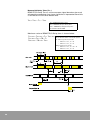
Remote I/O Update Timing Method
Under Remote I/O control, select the I/O update timing (Input and
Output processing) The I/O update (refresh) timing can be controlled
using the following modes.
•
SYSTEM SCAN Time < REMOTE I/O SCAN: Scan time asynchronous
mode.
•
SYSTEM SCAN Time > REMOTE I/O SCAN: Scan time synchronous mode.
Asynchronous mode
Normal I/O Scan < REMOTE I/O Scan
Synchronous mode
Normal I/O Scan > REMOTE I/O Scan
54
8
Power Up Sequence
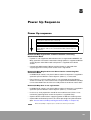
Power Up sequence
Slave Station POWER turns ON
(every Slave Station that is connected)
Set the Mode Selector Switch to PROG. mode
RUN mode set and Power up the Master Station (When you power
up the Master station, the communication LED of all the stations
will flash.)
Remote I/O Map registration and Slave Station connecting
Confirmation Mode
•
If power is not supplied to Slave Station that is registered to REMOTE I/O
Map, operation cannot be started even though power is supplied to Master
station System with RUN mode until power is supplied to the Slave
station.
•
Control with RUN mode if Master station System is operated after
supplying power to every Slave station that is registered.
Remote I/O Map Registration and Slave Station connecting Not
Confirmed Mode
•
In REMOTE I/O control, only for the Slave stations that power is supplied in
operation point of Master station System (above ③ ) is executed.
•
Even if there is a slave station which is not activated when the Master
station is turned On, slave stations that is registered with REMOTE I/O Map
can be controlled from the time turns ON power to the Slave station after.
Remote I/O Map that is not registration
•
In REMOTE I/O control, only for the Slave stations that power is supplied in
operation point of Master station System (above ③ ) is executed.
•
In this case, faulty operation should be occurred because I/O No. is not
realized by ignoring Slave station that power is supplied lately.
•
Operate Slave station before supplying power of Master station System.
•
Operate Master Station System at last after operating every Slave Station.
(See "Present Value I/O Map and Registration I/O Map" in Chapter 6.)
NOTE
When the I/O Map is registered, it is saved in the memory in the CPU.
55
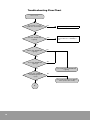
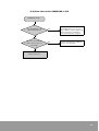
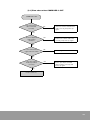
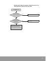
Reference Checking Flow chart
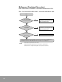
Flow chart checks if condition is satisfied or not about each Unit.
First of all, check Slave Unit that is connected with Master Unit
Start
Is Slave station No.
less than 32 Units?
N
Less than 32 Units.
Think about connecting the rest
with other Master Unit.
N
Less than 64Units.
Think about connecting the rest
with other Master Unit.
Y
Is I/O Unit
less than 64?
(1)
Y
Is I/O Point less than
1024 points?
N
Less than 1,024 points. (2)
Y
In I/O point, change base word No. of each master area by using WINGPC
S/W Initial value are R64, R96, R112 in case that is not configured. (3)
NOTE
56
(1)
The total of each Unit of Slave Unit.
(2)
[16 points] If 64occupied I/O is connected, it is 1,024 points.
(3)
Initial value is configured using 256 to 512 points (each area).
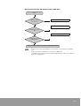
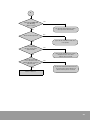
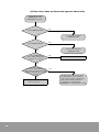
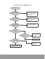
Check entire Remote I/O System with 1 CPU Unit.
Check
Less than 3Units.
Is Master station
less than 3?
Less than 64Units. (4)
Is I/O Unit less than
64?
(1)
Less than 1,024 points. (5)
Is I/O point less than
2048 points?
I/O point, limit ordinary I/O area by using WINGPC S/W. (6)
NOTE
(4)
In PLC System, if 8 slots backplane x 3 Slave Unit is connected with each Master
Unit,
(5)
[16 points] If 64 occupied I/O is connected, it is 1,024 points.
(6) Ordinary I/O area + Remote I/O area = Max. 1,024 points. Impossible to use ordinary
I/O in case of 1,024 points.
57
58
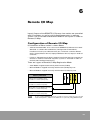
9
Function of Remote I/O System
Function of REMOTE I/O System
•
REMOTE I/O control Function
•
Shared Memory Access Function
•
Remote Programming Function (not supported in 700plus system)
Remote I/O Control Function
Basic function of REMOTE I/O System, possible to control I/O of Slave
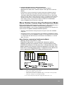
station in CPU Unit that Master Station is installed. This is called as
REMOTE I/O Control.
NOTE
Remote Programming Function is a function using communication port of Slave
Station (System that Slave Unit is installed to Master backplane).
Not supported in NX700plus series
59
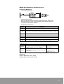
Shared Memory Access Function
•
Function that Shared Memory Data that is in advanced Unit (SCU High
Speed Counter (HSC), Positioning Unit, Analog Unit, etc.) Slave station
System is read and written in CPU Unit of Master station System.
•
Use the shared memory access instructions as follows:
[RMRD] instruction Data read from advanced Unit 's memory on a slave
station
[RMWR] instruction Data written to into advanced Unit 's memory on a
slave station
•
Example: With the shared memory access instruction, saved data into the
CPU Unit and read the data from the SCU Unit.
NOTE
•
Data that can be sent or received is Max. 32 words per a instruction.
•
While a shared memory access instruction is being executed, another shared
memory access instruction cannot be executed. shared memory access instruction. (Allowed 1 command per 1 SCAN)
•
Shared memory access instruction (RMRD and RMWR) about advanced
Unit have different execution method with shared memory access instruction (READ and WRITE).
•
Pay attention on executing RMRD and RMWR instruction.
In case of READ, WRITE instruction Execute and complete access to Shared
memory if execution condition is completed and instruction is executed.
(complete access with 1 scan)
In case of RMRD, RMWR instruction Executed actual request (receiving request and sending request) to Slave Station System in case that execution
condition is completed and instruction is executed. Because actual access
(execution of sending and receiving) is executed in case of executing “END”
instruction, scan is executed until access is completed. Therefore, in case of
executing access to Shared memory about advanced Unit to Slave Unit,
check execution condition by monitoring special relay and data register.
F8.14: Flag in case of executing Memory Access instruction (In case of execution == 1, execution completion ==0)
F8.15: Memory Access instruction Execution Result Flag (Normal completion
==0, abnormal completion ==1) Loop 1 (Master 1): F8.14, F8.15
Loop 2 (Master 2): F9.14, F9.15
Loop 3 (Master 3): F10.14, F10.15
60
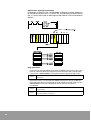
RMRD (Shared Memory Read Instruction)
Instruction Reference
•
Command Explanation
•
Operation Explanation
Write to register (PR2) by reading assigned word No. (NR1) from
Shared memory location (NR6) of SloN5) about Station (NN4) of
assigned Remote Network (NN3).
•
Assignment of each item
Item
Contents
NR1
Data word No. to Read
RR2
Head address of word upper land of CPU Unit that stores data which is Read
NN3
Remote Network No.
NN4
No. of Slave Unit
NN5
Slot location of advanced Unit that is installed in Slave Unit
NR6
Shared Memory Head Address in advanced Unit that is readable.
Flag Operation
Flags
Contents
Remarks
F8.14
Indicates that CPU is executing RMRD
(RMWR) instruction for Loop 1 (Master1).
Execution Completion == 0
Executing == 1
F8.15
Indicates that error occurs in case that CPU
executes RMRD (RMWR) instruction for Loop
1 (Master1).
Normal
Completion == 0
ERROR occurs == 1
In case of executing command for Loop 2 (Master2) and Loop 3
(Master3)
Loop 2 (Master2): F9.14, F9.15
Loop 3 (Master3): F10.14, F10.15
61
Explanation of program example
In program, If [R0.0] is ON, 10 word data of Shared memory address 0
to 9 of advanced Unit that is in SLOT No. 0 of Remote I/O Slave station
No. 2 is read, then store to data register W0~W9 of CPU Unit of Master
Station.
Flag operations
•
Impossible to execute RMRD instruction or RMWR instruction at the same
time for 1 Master. Make out program to execute when F08.14 (executing
Loop1) that is RMRD/RMWR instruction execution approval flag is OFF
F8.14
•
62
1: Cannot execute (RMRD/ RMWT instruction executing)
0: Execute
Receiving request is executed with RMRD instruction. Actual handling is
executed when Scan is completed. Use F08.14/F08.15 (using Loop 1) that is
RMRD/RMWR instruction completion flag to check if execution is
completed.
F8.14
0: Normal End
1: Executing
F8.15
0: Normal
1: Command Executing Error
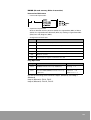
RMWR (Shared memory Write instruction)
Instruction Reference
•
Command Explanation
•
Operation Explanation
Write to Shared memory location (NR4) of assigned Slot (NN3) of Slave
(NN2) of assigned Remote Network (NN1) by reading assigned word No.
(NR5) from No./Register (NN2).
•
Assignment of Each Item
Item
Contents
NN1
Remote Network No. (Loop No.)
NN2
Slave Unit No. that is interfaced with Loop
NN3
SLOT No. that advanced Unit is installed to write data
NR4
Head location (word location) of shared memory to write
NR5
Word No. to write
NR6
Data to write or register in CPU that has a data
Flag Operation
Flags
Contents
Remarks
F8.14
Indicates that CPU is executing RMRD
(RMWR) instruction for Loop 1 (Master1).
Execution Completion == 0
Executing == 1
F8.15
Indicates that error occurs in case that CPU
executes RMRD (RMWR) instruction for Loop
1 (Master1).
Normal
Completion == 0
ERROR occurs == 1
In case of executing command for Loop 2 (Master2) and Loop 3
(Master3)
Loop 2 (Master2): F9.14, F9.15
Loop 3 (Master3): F10.14, F10.15
63
Explanation of Program Example
In program, if [R0.0] is ON, write 10 words of data register W0 to W9 of
CPU Unit of Master Station from Shared memory address 0 of
advanced Unit that is in SLOT No.0 of Remote I/O Slave Station No.2.
Write shared memory location (0) of assigned Slot (0) of Slave (02) of
assigned Remote Network (01) by reading assigned word No. (10)
from No./Register (W0).
Flag operations
•
Impossible to execute RMRD instruction or RMWR instruction at the same
time for 1 Master. Make out program to execute when F08.14 (executing
Loop1) that is RMRD/RMWR instruction execution approval flag is OFF
F8.14
•
64
1: Cannot execute (RMRD/ RMWT instruction executing)
0: Execute
Receiving request is executed with RMRD instruction. Actual handling is
executed when Scan is completed. Use F08.14/F08.15 (using Loop 1) that is
RMRD/RMWR instruction completion flag to check if execution is
completed.
F8.14
0: Normal End
1: Executing
F8.15
0: Normal
1: Command Executing Error
Example of Sequence Program using Shared Memory Access
Instruction
Advanced Unit (below is SCU) is installed on a Master backplane
together with a Slave Station.
Example of program of access the memory in the advanced Unit (SCU)
from the CPU on its Master Station.
EXAMPLE
Simple Memory Access
Slave Station No.: Station No.1
Installing location of advanced Unit (SCU): slot No.1 (2nd
slot)
• Write data (15 words) of W100 to W114 of CPU Unit to
Shared memory location 500 of advanced Unit of Slave
Station System.
• Store to W200 to W214 of CPU Unit by reading 15 words
data that is written to advanced Unit (ex. SCU).
NOTE
Program that F08.14 (Executing approval flag of Slave Station 1) is OFF in case
of executing shared memory access instruction.
•
In case of using Master Unit 2: F9.14
•
In case of using Master Unit 3: F10.14
Pay attention that execution of Shared memory access instruction is overlapped
in same SCAN.
65
Flow Chart (Simple Memory Access)
Memory Access START Condition ON
NO
F8.14: OFF?
YES
Execute Memory Write Instruction
Process 0
F8.14: OFF?
NO
YES
Execute Memory Read Instruction
Process 1
NO
F8.14: OFF?
YES
To Process 2
66
Example of Program (Simple Memory Access)
Write data with Shared memory
(Process 0). Execute RMWR
Write 15 words data from address
500 of shared memory in W100.
Read data with shared memory
(Process 1). Execute RMRD. Store
15 words data from W200 by
reading in address 500 of shared
memory.
67
68
10
Finding the cause of an Error and
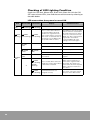
Correcting the Error
Explain checking method and correcting the Error when error occurs
using Remote I/O System
Checking Sequence of Error
1. Checking LED Lighting Condition
Check lighting condition of ALARM and COMM. (or COM.) of Master Unit,
Slave Unit.
LED's
name
ALARM
COMM.
(COM.)
Condition
Content of Error
Correcting
the Error
Lighting
Error on Unit
Change
Slow
blinking
(1sec cycle)
Error on communication (disconnection of
transmission cable or power off).
Check
transmission line
and place
Lights-out
Error on transmission (error on setting of
transmission or termination Unit), Slave
Unit and Master Unit cannot communicate
each other
Checking Error
2. Determining what kind of error has occurred
Checking of BIT of special register F8, F9, F10 of CPU Unit and special data
register SR197, SR198, SR199.
3. Checking Station No. of Slave Unit that error occurs
Check Slave Unit and place that error occurs. Especially, check content of
special data register SR294 to SR299.
69
Error Code of Remote I/O
In case of error using Remote I/O System, content of error is stored to
special data register SR261, SR262, SR263 of CPU Unit.
Content of special data register SR261, SR262, SR263 shows content of
ERROR with 8 bit about each transmission line of Master Unit 1 to 3.
(Upper 8 bit is used in system.)
If error occurs, bit of ① to ⑧ that corresponds to error content is “1”.
EXAMPLE
Bit No
If SR199 is “8H”, it indicates that termination Unit setting
error of Master Unit 3 occurs (“8H”=”00000000 00001000”;
bit 3 ( ④ )=”1”).
CPU
Operation
Content
0
Remote I/O error on communication
(Slave Unit that cannot be
communicated occurs.)
1
Transmission Error
2
Arrangement
(1)
Selection (2)
Check power OFF and disconnection of
transmission line.
Selection (2)
Check transmission error or setting of station
No.
Inhibited Unit is installed to Slave
Station System.
Stop
Remove inhibited Unit.
3
Remote I/O Termination Unit Error
Transmission
Set setting of Remote I/O terminal station
4
Exceed total slot No. per a Master
Station
Stop
Use in usage range (Max. 64 slots)
5
Exceed total I/O point per a Master
Station
Stop
Use in usage range. (Max. 1, 024 points)
6
Instant interruption of electric power of
Slave Station (1)
Transmission
Execute power check
7
Unit error of Slave Station System (1)
Selection (2)
Verify error, fuse disconnection, and advanced
Unit traffic occurs. Execute I/O check
(1)
Precaution
Possible to limit Slave Unit
Stop or operation of CPU Unit can be selected by setting of system
register.
(1)
(2)
70
Checking of Slave Station that Error Occurs
In case of Communication Error, Transmission Error, Instant
Interruption of Power, and Unit Error of Slave Station using Remote I/O
System, possible to check error place (Loop and No. of Slave Station
that error occurs) by monitoring special data register using WINGPC
S/W or Handy-Loader (PGM-500).
Content of Checking
•
Loop No. (Master number) of Master Unit that error occurs right now.
•
Station No. of Slave Unit that error has occurred until now (Accumulation
Value).
•
Station No. of Slave Unit System that error (fuse disconnection, traffic,
etc.) occurs to installed Unit.
•
Station No. of Slave Unit that instant power interruption.
Checking Sequence
1. Check transmission line that error occurs.
•
•
If error occurs in transmission line of Remote I/O, special internal relay
F8, F9, F10 register that correspondents to the transmission line is ON.
Relay No.
Content
F8.9, F8.10, F8.11, F8.12
ON when an error occurs in Master 1
F9.9, F9.10, F9.11, F9.12
ON when an error occurs in Master 2
F10.9, F10.10, F10.11, F10.12
ON when an error occurs in Master 3
Content and transmission line of faulty operation can be checked by
monitoring special data register F8, F9, F10.
EXAMPLE
The contact point is ON among contact points F9.9, F9.10,
F9.11, F9.12. (Faulty operation is executed in Master 2)
71
2. Check error place. [Checking of instant power interruption and Slave Unit
that error occurs] To check Slave Unit that instant power interruption
occurs, monitor SR274, SR276, SR278 register.
Loop 1 (Master 1): SR274,SR275
Loop 2 (Master 2): SR276, SR277
Loop 3 (Master 3): SR278, SR279
Bit that corresponds to station No. of Master Unit that constant power
interruption occurs is “1”.
EXAMPLE
If SR276=”0002H”, Error occurs to Slave Station No. 2 of
Master 2 (Loop2).
(“2H”=00000000 00000010: bit 1 (No.2)=“1”)
3. Checking of Slave Station that is connected right now To check information
of Slave Station that operates by connecting, monitor SR264, SR266,
SR268 register.
Loop 1 (Master 1): SR264, SR265
Loop 2 (Master 2): SR266, SR267
Loop 3 (Master 3): SR268, SR269
Bit that corresponds to station No. of Slave Unit that is connected right
now is “1”.
EXAMPLE
72
If SR265=“0002H”, Slave Station No. 2 of Master 1(Loop1) is
connected.
(“2H”= 00000000 00000010: bit 1 (No.2)=“1”)
11
Troubleshooting
This section provides methods for troubleshooting the operation of
the Remote I/O System.
73
Troubleshooting Flow Chart
Error occurs
Are all Units correctly
installed on the backplane
NO
Install correctly.
YES
CPU Unit ALARM LED
Lighting?
YES
Refer to “Troubleshooting” of
System Manual” of NX700plus
PLC.
NO
Master Unit ALARM LED
Lighting?
YES
NO
Slave Unit ALARM LED
Lighting?
YES
[1] To Flow Chart of ALARM LED
Lighting
NO
Master Unit COMM.LED
Fast Blinking (0.2sec
cycle)?
YES
1
74
NO
[2] To Flow Chart when the Master
Unit operates abnormally
1
Slave Unit COMM.LED
Fast Blinking
(0.2sec cycle)?
NO
[3] To Flow chart when the Slave
Unit operates abnormally
YES
YES
Does the CPU operate?
[5] To Flow chart when CPU does
not operate
NO
Does Input/Output
function of the slave
station work?
YES
[6] To Flow chart when the Input/
Output function of a slave
station does not work
NO
Does the memory
access function of an
advanced Unit on a slave
station work?
YES
YES
[7] To Flow chart when the memory
access function of the advanced
Unit's memory does not work
Please contact us.
75
[1] Flow chart when ALARM LED is ON
ALARM LED is ON
Check the by Power Supply by
switching it ON and OFF.
Does the LED come
ON frequently?
NO
This may be a temporary due to
noise. Restart the system and
observe the operation.
76
YES
Replace with a spare Unit on board if
available. If the error occurs again,
please contact us.
[2] Flow chart when the Master Unit operates abnormally
COMM.LED is No Fast
Blinking (0.2sec cycle).
COMM.LED is OFF?
YES
[2-1]To Flow chart when
COMM.LED of Master Unit is OFF.
NO
COMM.LED is ON?
YES
[2-2]To Flow chart when COMM.
LED of Master Unit is ON.
NO
Is the COMM.LED on the
Master Unit flashing slowly
(1 sec. cycle)?
NO
Please contact us.
YES
Is the Mode
selector switch No.7 on the
Master Unit set to ON (operation
stop mode during
communication error) position?
NO
Please contact us.
YES
The Slave station will not operate
normally when a communication error
occurs. Check the faulty slave station and
check the operation according to flow chart
the COMM.LED on a Slave station is ON.
77
[2-1] Flow chart when COMM.LED is OFF.
COMM.LED is OFF
Is the Power LED of
Power Unit ON?
YES
See “Troubleshooting” of System
Manual of NX700plus PLC.
NO
Turns OFF the power supply to all
device. Connect the Slave station
and power up again.
NO
Is the Slave station
operate?
YES
Is the transmission
Cable connected
correctly?
NO
Turns OFF the power supply to all
device. Connect transmission cable
correctly, and power up again.
YES
Is the terminal station
number specified
correctly?
YES
Please contact us.
78
NO
Turns OFF the power supply to all
device. Specify the terminal station
correctly, and power up again.
[2-2] Flow chart when COMM.LED is ON
COMM.LED is ON
Is the ALARM LED on the
Master Unit flashing?
YES
The slave Station setting error
and illegal Unit error is occurs.
Turns OFF the power supply to all
device. Allots the I/O number
correctly and power up again.
NO
Are more than 3 Master
Units connected to one
CPU Unit?
YES
Connect a maximum of 3 Master
Units to one CPU Unit.
NO
Please contact us.
79
[3] Flow chart when the Slave Unit operates abnormally
COMM.LED No Fast
Blinking (0.2sec cycle).
Is the COMM.LED OFF?
YES
[3-1] To flow chart when
COMM.LED is OFF
NO
Is the COMM.LED ON?
YES
[3-2] To flow chart when
COMM.LED is ON
NO
Is the COMM.LED
on the Slave Unit flashing
slowly (l sec. cycle)?
NO
Please contact us.
YES
Is the Mode selector
switch No.7 on the Master Unit
set to OFF (operation stop mode
during communication error)
position?
NO
Please contact us.
80
YES
The Slave station will not operate
normally when a communication
error occurs. Check the faulty slave
station and check the operation
according to 3-1 flowchart the
COMM.LED on a Slave station is OFF.
[3-1] Flow chart when COMM.LED is OFF
COMM.LED is OFF
Is the transmission
cable connected
correctly?
NO
Turns OFF the power supply to
all device.Connect transmission
cable correctly, and power up
again.
YES
Are there duplicate
Slave Station
Number?
NO
Turns OFF the power supply to
all device.Set Slave Station No.
correctly, and power up again.
YES
Is the Slave station
registered in the CPU?
NO
Please register the slave station.
YES
Is the slave station
number specified
correctly?
NO
Turns OFF the power supply to all
device. Specify the terminal
station number correctly, and
power up again.
YES
Please contact us.
81
[3-2] Flow chart when COMM.LED is ON
COMM.LED is ON
Is the ALARM LED on the
Slave Unit flashing?
The slave Station setting error is
occurs. Turns OFF the power
supply to all device. Set the slave
station number correctly and
power up again.
YES
NO
Is the communication
cable connected
correctly?
Turns OFF the power supply to
all device. Connect the
transmission cable correctly and
power up again.
NO
YES
Is the setting for the
port used on the
Master Unit correct?
Turns OFF the power supply to all
device. Specify the terminal
station correctly and power up
again.
NO
YES
Is the allocated
the I/O Map?
NO
YES
Is the power up
sequence correct?
YES
Is the slave station
register in the CPU?
NO
Correct perform the
power up sequence for
the Master Unit and
slave stations.
Please contact us.
NO
Register the slave station
For registration
procedures.
Please contact us.
82
[4] Flowchart when CPU Unit does not run
CPU Unit does not operate
Is the CPU Unit RUN
Mode?
NO
Set the RUN position with the
mode selector switch on the CPU
Unit.
YES
Is the PROG.LED on the
CPU Unit flashing?
NO
See “Troubleshooting” of
System Manual of NX700plus
YES
Is an Remote I/O Map
registered?
NO
YES
Is the confirmation mode
for connection of a Slave
station selected?
NO
YES
Are all registered Slave
station power up?
NO
Power up all I/O Map registered
Slave station.
YES
Is the transmission cable
connected correctly?
YES
Please contact us.
NO
Turns OFF the power supply all
devices. Connect the
transmission cable correctly, and
power up again.
83
[5] Flow chart when the Input/Output function of a slave
station does not work
Input/Output function
does not work
Is I/O Map set correctly?
NO
Allocate a valid the I/O number.
YES
Is the program
content correct?
NO
Correct the program.
YES
Does I/O function on the
Slave Link Unit?
NO
The Slave Link Unit (Slave station)
may be faulty. Please contact us.
NO
The Remote I/O System may be
faulty. Please contact us.
YES (Slave Unit)
Does the other Input/
Output Units operate
correctly?
YES
The Input/Output Unit may be
faulty. Please contact us.
84
[6] Flow chart when the memory access function of the
advanced Unit's memory does not work
Shared Memory No
Access.
Is the advanced Unit
installed correctly?
NO
Install the advanced Unit correctly.
YES
Is control data in the
shared memory access
instruction set
correctly?
NO
Set correctly.
YES
Replace with a spare Unit or
board if available. If the error
occurs again. Please contact us.
85
Checking of LED Lighting Condition
Check the CPU Unit, Master Unit, Slave Unit, Slave link Unit for ON/
OFF status of their LEDs, then find the cause of the error by referring to
the table below.
LED status when the system is turned ON
CPU
Unit
PROG.
(ON)
PROG.
(Blinking)
Master Unit
Slave Unit
COMM.
(Fast blinking)
COMM.
(Fast blinking)
Display
Countermeasures
COMM.
(Fast blinking)
Normal
COMM.
(Fast blinking)
There is slave station which is
not activated although its I/O
numbers are registered in the
CPU. (“Slave station connection
wait mode” is activated. Even if
the CPU goes to the RUN mode,
the operation will not start.)
Turn ON the power go the slave
stations which is not activated.
Check the transmission cable to
see if it is connected correctly.
Make sure all the slave stations
registered in the CPU are
connected Match all of the
settings, then restart again.
Temporary error caused by noise
Restart the system.
Error on the Master Unit.
Please contact us.
Temporary error caused by noise
Restart the system.
ALARM
(ON)
● ALARM
(OFF))
ERROR
(ON)
Error on the Slave station.
Please contact us.
More than 3 Master Units
are installed.
Install up to 3, Restart the
system.
COMM.
(Fast blinking)
ALARM
(Blinking)
There are Unit which cannot be
installed on a slave station where
a Slave Unit is installed.
Check the advanced Units
which can be installed on a
slave station together with a
Slave Unit. Reconfigure the
slave station. Remove any Unit
which cannot be installed on
the station.
COMM.
(Fast blinking)
Terminal stations are not
assigned correctly.
Both ends of transmission cable
for correct connection. Check
the ports of the Master Unit.
COMM.
(ON)
X
86
ALARM
(ON)
CPU
Unit
Master Unit
Slave Unit
○ COMM.
(ON)
ERROR
(ON)
● COMM.
(OFF)
X
COMM.
(ON)
ALARM
(Blinking)
Display Content
Countermeasures
Transmission Cable is not
connected correctly.
Check the transmission cable
for correct connection. Check
the ports of the Master Unit.
Slave stations is not registered.
Register the slave station, and
then restart the system.
Transmission Cable is not
connected correctly.
Turn ON the power of the slave
stations which is not activated.
The Slave stations number is
duplicated
Make sure the transmission
cable is connected correctly.
Make sure all the slave stations
registered in the CPU are
connected.
The terminal stations are not
assigned correctly
Connect the settings, then
restart.
The Slave stations number is out
range (1 thru 32)
Assign a slave station number
within the applicable range (1
thru 32)
LEDs Status during the operation
CPU
Unit
RUN
(ON)
ERROR
(ON)
ERROR
(ON)
Master Unit
Slave Unit
COMM.
(Fast blinking)
COMM.
(Fast blinking)
COMM.
(Fast blinking)
COMM.
(Fast blinking)
Display Content
Countermeasures
Normal
Error on a slave station Unit
where a slave Slave Unit is also
installed.
Exchanged bad Unit with good
one, then restart the system
Termination station are not set
correctly.
Both ends of transmission path
must be terminal stations.
COMM.
(Fast blinking)
● COMM.
(OFF)
This Slave station cannot be
communicate with the Master
station. (Communication Error)
Check the transmission cable
for correct connections, then
restart the system.
COMM.
(Slow blinking)
COMM.
(Slow blinking)
Other Slave stations have
a transmission error. (A slave
station whose communication
LED is flashing is normal)
Check the transmission cable
for correct connections, then
restart the system.
COMM.
(Slow blinking)
● COMM.
(OFF)
This Slave station whose
communication LED is OFF has a
communication LED is flashing is
normal)
Check the transmission cable
for correct connections, then
restart the system.
87
88
NX700/NX70 Remote I/O System User Manual
www.samsungautomation.co.kr
Rockwell Samsung Automation
Technical Support
447-6, Gongse-Ri, Giheung-Eup, Youngin-City,
Gyeonggi-Do, South Korea, 449-902
Tel: 82-31-280-4700 Fax: 82-31-280-4900
Export Sales Team
Tel: 82-31-280-4768 Fax: 82-31-280-4900
Trademarks not belonging to Rockwell Samsung
Automation are property of their respective companies.
Publication RSA-NX700-UM011B-EN-P - July 2005 90
Copyright © 2005 Rockwell Samsung Automation. All rights reserved. Printed in Korea.